EP2949918A1 - Kraftstoffinjektor - Google Patents
Kraftstoffinjektor Download PDFInfo
- Publication number
- EP2949918A1 EP2949918A1 EP15163483.9A EP15163483A EP2949918A1 EP 2949918 A1 EP2949918 A1 EP 2949918A1 EP 15163483 A EP15163483 A EP 15163483A EP 2949918 A1 EP2949918 A1 EP 2949918A1
- Authority
- EP
- European Patent Office
- Prior art keywords
- nozzle
- coupler
- fuel injector
- actuator
- nozzle needle
- Prior art date
- Legal status (The legal status is an assumption and is not a legal conclusion. Google has not performed a legal analysis and makes no representation as to the accuracy of the status listed.)
- Granted
Links
- 239000000446 fuel Substances 0.000 title claims abstract description 37
- 230000008878 coupling Effects 0.000 claims abstract description 23
- 238000010168 coupling process Methods 0.000 claims abstract description 23
- 238000005859 coupling reaction Methods 0.000 claims abstract description 23
- 238000002485 combustion reaction Methods 0.000 claims abstract description 10
- 238000002347 injection Methods 0.000 claims abstract description 9
- 239000007924 injection Substances 0.000 claims abstract description 9
- 238000007789 sealing Methods 0.000 claims abstract description 8
- 230000009471 action Effects 0.000 claims description 2
- 230000004913 activation Effects 0.000 description 4
- 238000004519 manufacturing process Methods 0.000 description 4
- 238000011161 development Methods 0.000 description 3
- 230000018109 developmental process Effects 0.000 description 3
- 230000009467 reduction Effects 0.000 description 3
- 230000003321 amplification Effects 0.000 description 1
- 230000008901 benefit Effects 0.000 description 1
- 238000004891 communication Methods 0.000 description 1
- 238000011038 discontinuous diafiltration by volume reduction Methods 0.000 description 1
- 238000003199 nucleic acid amplification method Methods 0.000 description 1
- 238000000926 separation method Methods 0.000 description 1
Images
Classifications
-
- F—MECHANICAL ENGINEERING; LIGHTING; HEATING; WEAPONS; BLASTING
- F02—COMBUSTION ENGINES; HOT-GAS OR COMBUSTION-PRODUCT ENGINE PLANTS
- F02M—SUPPLYING COMBUSTION ENGINES IN GENERAL WITH COMBUSTIBLE MIXTURES OR CONSTITUENTS THEREOF
- F02M51/00—Fuel-injection apparatus characterised by being operated electrically
- F02M51/06—Injectors peculiar thereto with means directly operating the valve needle
- F02M51/0603—Injectors peculiar thereto with means directly operating the valve needle using piezoelectric or magnetostrictive operating means
-
- F—MECHANICAL ENGINEERING; LIGHTING; HEATING; WEAPONS; BLASTING
- F02—COMBUSTION ENGINES; HOT-GAS OR COMBUSTION-PRODUCT ENGINE PLANTS
- F02M—SUPPLYING COMBUSTION ENGINES IN GENERAL WITH COMBUSTIBLE MIXTURES OR CONSTITUENTS THEREOF
- F02M61/00—Fuel-injectors not provided for in groups F02M39/00 - F02M57/00 or F02M67/00
- F02M61/16—Details not provided for in, or of interest apart from, the apparatus of groups F02M61/02 - F02M61/14
- F02M61/167—Means for compensating clearance or thermal expansion
-
- F—MECHANICAL ENGINEERING; LIGHTING; HEATING; WEAPONS; BLASTING
- F02—COMBUSTION ENGINES; HOT-GAS OR COMBUSTION-PRODUCT ENGINE PLANTS
- F02M—SUPPLYING COMBUSTION ENGINES IN GENERAL WITH COMBUSTIBLE MIXTURES OR CONSTITUENTS THEREOF
- F02M2200/00—Details of fuel-injection apparatus, not otherwise provided for
- F02M2200/70—Linkage between actuator and actuated element, e.g. between piezoelectric actuator and needle valve or pump plunger
- F02M2200/703—Linkage between actuator and actuated element, e.g. between piezoelectric actuator and needle valve or pump plunger hydraulic
- F02M2200/704—Linkage between actuator and actuated element, e.g. between piezoelectric actuator and needle valve or pump plunger hydraulic with actuator and actuated element moving in different directions, e.g. in opposite directions
-
- F—MECHANICAL ENGINEERING; LIGHTING; HEATING; WEAPONS; BLASTING
- F02—COMBUSTION ENGINES; HOT-GAS OR COMBUSTION-PRODUCT ENGINE PLANTS
- F02M—SUPPLYING COMBUSTION ENGINES IN GENERAL WITH COMBUSTIBLE MIXTURES OR CONSTITUENTS THEREOF
- F02M2200/00—Details of fuel-injection apparatus, not otherwise provided for
- F02M2200/70—Linkage between actuator and actuated element, e.g. between piezoelectric actuator and needle valve or pump plunger
- F02M2200/703—Linkage between actuator and actuated element, e.g. between piezoelectric actuator and needle valve or pump plunger hydraulic
- F02M2200/708—Linkage between actuator and actuated element, e.g. between piezoelectric actuator and needle valve or pump plunger hydraulic with hydraulic chambers formed by a movable sleeve
Definitions
- the invention relates to a fuel injector for injecting fuel into a combustion chamber of an internal combustion engine having the features of the preamble of claim 1.
- a fuel injector for injecting fuel into a combustion chamber of an internal combustion engine which has for releasing and closing at least one injection port a liftable in a high-pressure bore of a nozzle body nozzle needle and a piezoelectric actuator for controlling the lifting movement of the nozzle needle.
- the piezoactuator is hydraulically coupled to the nozzle needle and actuates a master piston which acts as a displacer in a coupling space, while the nozzle needle is coupled in a coupled manner to a slave piston which displaces the coupling space in the coupling space.
- the piezoelectric actuator and the master piston on the one hand and the nozzle needle and the slave piston on the other hand have different lifting axes, these lifting axes are arranged parallel to each other and laterally offset.
- the direction of action of the piezoelectric actuator corresponds to the direction of movement of the nozzle needle, so that the activation of the piezoelectric actuator generates a closing force acting on the nozzle needle.
- fuel injectors with so-called “reversing couplers” are known, which allow a reversal of the effective direction of the piezoelectric actuator, so that the activation of the piezoelectric actuator takes place for opening the nozzle needle.
- a fuel injector is an example of the published patent application DE 10 2011 003 443 A1 out. at Activation lasts the piezoelectric actuator and moves the master piston against the spring force of a biasing spring in the direction of the nozzle needle, so that the pressure rises in a first coupler space.
- the first coupler space communicates with a further coupler space, which is arranged below a coupler piston connected to the nozzle needle, so that the increase in pressure caused in the further coupler space leads to the lifting of the nozzle needle from its sealing seat.
- a further coupler space which is arranged below a coupler piston connected to the nozzle needle, so that the increase in pressure caused in the further coupler space leads to the lifting of the nozzle needle from its sealing seat.
- the piezoelectric actuator is terminated, which then contracts again, the spring force of the biasing spring leads to the return of the master piston.
- the two coupler spaces are relieved, while in a further coupler volume acting on the nozzle needle closing pressure is built up, so that in the sequence and the nozzle needle is returned to its sealing seat.
- the present invention has for its object to simplify the structure of a fuel injector with eccentrically arranged piezoelectric actuator and reversing coupler.
- the fuel injector proposed for injecting fuel into a combustion chamber of an internal combustion engine comprises a nozzle body and a nozzle needle which is liftably received for releasing and closing at least one injection opening in a high-pressure bore of the nozzle body and acted upon in the direction of a sealing seat by the spring force of a nozzle spring. Furthermore, the fuel injector comprises a piezoelectric actuator, which is hydraulically coupled to control the lifting movement of the nozzle needle via a coupling device with the nozzle needle.
- the coupling device compensates for an axial offset between a longitudinal axis of the nozzle needle and a longitudinal axis of the piezoelectric actuator. In addition, it reverses the effective direction of the piezoelectric actuator.
- the coupling device comprises a coupler piston which has an actuator-side hydraulic active surface for limiting an actuator-side Coupler volume and a nozzle-side hydraulic active surface for limiting a nozzle-side Kopplervolumens has and is interspersed to connect the two volumes of an axial bore.
- the axial bore in the coupler piston is costly to be produced connecting holes in one or more body parts of the fuel injector, so that the manufacturing cost is significantly reduced.
- An inventive fuel injector is therefore simple and inexpensive to produce.
- the nozzle-side hydraulic active surface of the coupler piston on the coupler volume is opposite a hydraulic active surface of the nozzle needle, which is preferably formed on an end face of the nozzle needle facing the piezoelectric actuator.
- the coupler piston is thus hydraulically coupled via the coupler volume with the nozzle needle.
- the pressure prevailing in the nozzle-side coupler volume pressurizes the nozzle needle with a hydraulic force acting in the closing direction.
- the hydraulic force acting in the closing direction can be reduced to such an extent that the nozzle needle opens.
- the nozzle-side coupler volume is connected to the actuator-side coupler volume via the axial bore in the coupler piston, the pressure prevailing in the actuator-side coupler volume can also be lowered to open the nozzle needle. This can be done by moving the coupler piston in the direction of the nozzle needle to increase the actuator-side coupler volume. The pressure in the actuator-side coupler volume drops.
- the movement of the coupler piston in the direction of the nozzle needle has the consequence that the volume of the nozzle-side coupler volume is reduced.
- the volume reduction should actually lead to an increase in pressure.
- the nozzle-side coupler volume is in communication with the actuator-side coupler volume via the axial bore in the coupler piston, a pressure reduction in the coupler volume on the nozzle side can be effected at the same time via the pressure reduction in the actuator-side coupler volume. This is especially true if, according to a preferred embodiment of the invention, the nozzle-side hydraulic effective area of the coupler piston is smaller than the actuator-side hydraulic effective area.
- the area ratio of the hydraulic active surfaces on the coupler piston is decisive, whether in the nozzle-side coupler volume, a pressure increase or a Pressure drop is effected. Furthermore, a translation can be effected via the area ratio.
- the ratio is generally to be reduced by a factor of 1
- the area ratio can be chosen such that the ratio is reduced by less than a factor of one. Because in the present case, the area ratio of the hydraulic active surfaces on the coupler piston is freely selectable.
- the coupler piston is designed to be single or multi-stepped for this purpose.
- the coupler piston of the coupling device is arranged in a high-pressure chamber of the fuel injector.
- the supply of high-pressure fuel can therefore be carried out substantially centrally over a wide range.
- Zulaufbohrungen in the body components of the fuel injector can be omitted, so that its production is further simplified.
- the high-pressure chamber of the fuel injector is preferably separated via a coupler plate from a low-pressure chamber, in which further preferably the piezoelectric actuator is accommodated. The arrangement of the actuator in low pressure favors its life.
- the coupler plate limits the actuator-side coupler volume in the axial and / or radial direction.
- the actuator-side coupler volume is formed in the coupler plate, that is, the coupler plate limits the coupler volume in the axial and radial directions.
- a recess may be formed in the coupler plate, in which the actuator-side end of the coupler piston is received such that between the coupler piston and the bottom of the recess a usable volume as a coupler volume remains.
- a guide of the coupler piston can be effected in this way, a guide of the coupler piston.
- the nozzle-side coupler volume is divided by a throttle plate into a first partial volume and a second partial volume.
- the two sub-volumes are also connected via a arranged in the throttle plate bore, in which preferably a throttle is formed.
- the separation of the nozzle-side Kopplervolumens in two sub-volumes has the advantage that in the region of the throttle plate, the desired axial offset between the longitudinal axis of the nozzle needle and the longitudinal axis of the actuator can be realized.
- the coupler piston is preferably arranged coaxially to the longitudinal axis of the piezoelectric actuator in this case.
- the nozzle-side end of the coupler piston is received in a sleeve, which is supported on the throttle plate and acted upon in the direction of the throttle plate by the spring force of a spring.
- the supported on the throttle plate sleeve is displaceable in the radial direction relative to the throttle plate and allows in this way the compensation of manufacturing and / or assembly tolerances.
- the sleeve can also be used to limit the first sub-volume of the nozzle-side coupler volume in the radial direction on this side of the throttle plate.
- the actuator end of the nozzle needle is received in a sleeve which is supported on the throttle plate and acted upon in the direction of the throttle plate by the spring force of the nozzle spring.
- the sleeve is in turn displaceable in the radial direction relative to the throttle plate and thus enables the compensation of manufacturing and / or assembly tolerances.
- the sleeve can be used to limit the second sub-volume of the nozzle-side coupler volume beyond the throttle plate in the radial direction.
- the actuation of the coupler piston of the coupling device via the piezoelectric actuator requires an active connection of the piezoelectric actuator with the coupler piston.
- the piezoelectric actuator is operatively connected via a pressure pin to the coupler piston.
- the pressure pin can be guided through the coupler plate, which separates the high-pressure chamber from the low-pressure chamber, in which the piezoelectric actuator is arranged.
- the pressure pin preferably has a small guide pressure gauge, so that the leakage in the guide region of the pressure pin is limited.
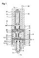
- the fuel injector shown in longitudinal section comprises a plurality of body components, namely a nozzle body 1, a throttle plate 19, a sleeve-shaped body member 26, a coupler plate 17 and a holding body 27, which are braced axially via a clamping nut 34.
- a piezoelectric actuator 7 is accommodated for actuating a liftable nozzle needle 2.
- the liftable nozzle needle 2 is accommodated for releasing and closing at least one injection opening 3 in a high-pressure bore 4 of the nozzle body 1. In this case, the nozzle needle 2 cooperates with a sealing seat 5.
- the nozzle needle 2 is acted upon by the spring force of a nozzle spring 6, which is supported in the illustrated embodiment on the one hand on a collar 33 of the nozzle needle 2 and on the other hand on a sleeve 24 which surrounds a aktor workedes end of the nozzle needle 2.
- the spring force of the nozzle spring 6 holds the sleeve 24 in abutment with the throttle plate 19th
- the nozzle needle 2, the sleeve 24 and the throttle plate 19 define a partial volume 13.2, which communicates via a formed in the throttle plate 19 throttle bore 20, 21 with a further sub-volume 13.1.
- the further partial volume 13.1 is bounded by the throttle plate 19, a sleeve 22 supported thereon and a lifting coupler piston 9 of a coupling device 8 whose nozzle-side end is received in the sleeve 22.
- the sleeve 22 is acted upon by the spring force of a spring 23, which holds the sleeve 22 in abutment with the throttle plate 19.
- the two sub-volumes 13.1, 13.2 together form a nozzle-side coupler volume 13 of the coupling device 8, which is connected via an axial bore 15 in the coupler piston 9 in conjunction with an actuator-side coupler volume 14 of the coupling device 8.
- the pressure in the two coupler volumes 13, 14 is thus approximately equal.
- the actuator-side coupler volume 14 is formed in the coupler plate 17, which is equipped for this purpose with a hollow cylindrical projection which surrounds the actuator-side end of the coupler piston 9.
- the coupler plate 17 also serves to separate a high-pressure chamber 16, in which the coupling device 8 is received, from a low-pressure chamber 18, which is formed in the holding body 27 and serves to receive the piezoelectric actuator 7.
- a pressure pin 25 is guided by the coupler plate 17, so that the piezoelectric actuator 7 and the coupler piston 9 are mechanically coupled.
- the coupler piston 9 and the two coupler volumes 13, 14 comprehensive coupling device 8 is used for the hydraulic coupling of the piezoelectric actuator 7 with the nozzle needle 2, so that the lifting movement of the nozzle needle 2 via the piezoelectric actuator 7 is directly controlled.
- the coupling device 8 is designed such that the effective direction of the piezoelectric actuator 7 is reversed. Furthermore, an amplification of the actuator force is effected via the coupling device 8.
- the actuator 7 For closing the injection opening 3, the actuator 7 is deactivated. This has the consequence that the actuator 7 contracts again and the spring force of the spring 23 resets the coupler piston 9 in its initial position. This is accompanied by a reduction of the actuator-side coupler volume 14, so that herein a pressure increase is effected. For the reasons already mentioned above is also a pressure increase in nozzle-side coupler volume 13 causes, so that a hydraulic closing force acts on a hydraulic active surface 12 of the nozzle needle 2. This in conjunction with the spring force of the nozzle spring 6 causes the nozzle needle 2 is returned to the sealing seat 5 and the injection is terminated.
- the connection of the low-pressure space 18 to a return 32 is provided. Since the illustrated fuel injector is a directly operable injector, however, the quantities to be discharged are small. In particular, no Abêtmenge of a servo valve as in indirectly operable fuel injectors.
Landscapes
- Engineering & Computer Science (AREA)
- Chemical & Material Sciences (AREA)
- Combustion & Propulsion (AREA)
- Mechanical Engineering (AREA)
- General Engineering & Computer Science (AREA)
- Fuel-Injection Apparatus (AREA)
Abstract
Description
- Die Erfindung betrifft einen Kraftstoffinjektor zum Einspritzen von Kraftstoff in einen Brennraum einer Brennkraftmaschine mit den Merkmalen des Oberbegriffs des Anspruchs 1.
- Aus der Offenlegungsschrift
DE 10 2008 002 412 A1 ist ein Kraftstoffinjektor zum Einspritzen von Kraftstoff in einen Brennraum einer Brennkraftmaschine bekannt, der zum Freigeben und Verschließen wenigstens einer Einspritzöffnung eine in einer Hochdruckbohrung eines Düsenkörpers hubbeweglich aufgenommene Düsennadel sowie einen Piezoaktor zur Steuerung der Hubbewegung der Düsennadel besitzt. Der Piezoaktor ist hierzu mit der Düsennadel hydraulisch gekoppelt und betätigt einen in einem Kopplungsraum verdrängerwirksamen Geberkolben, während die Düsennadel mit einem im Kopplungsraum verdrängerwirksamen Nehmerkolben hubgekoppelt ist. Um im Injektorkörper notwendige Hochdruckleitungen unterbringen zu können, besitzen der Piezoaktor und der Geberkolben einerseits und die Düsennadel und der Nehmerkolben andererseits unterschiedliche Hubachsen, wobei diese Hubachsen zueinander parallel und seitlich versetzt angeordnet sind. Die Wirkrichtung des Piezoaktors entspricht dabei der Bewegungsrichtung der Düsennadel, so dass die Aktivierung des Piezoaktors eine auf die Düsennadel wirkende Schließkraft erzeugt. - Darüber hinaus sind Kraftstoffinjektoren mit sogenannten "Umkehrkopplern" bekannt, die eine Umkehrung der Wirkrichtung des Piezoaktors ermöglichen, so dass die Aktivierung des Piezoaktors zum Öffnen der Düsennadel erfolgt. Ein solcher Kraftstoffinjektor geht beispielhaft aus der Offenlegungsschrift
DE 10 2011 003 443 A1 hervor. Bei Aktivierung längt sich der Piezoaktor und bewegt den Geberkolben entgegen der Federkraft einer Vorspannfeder in Richtung der Düsennadel, so dass der Druck in einem ersten Kopplerraum ansteigt. Der erste Kopplerraum steht mit einem weiteren Kopplerraum in Verbindung, der unterhalb eines mit der Düsennadel verbundenen Kopplerkolbens angeordnet ist, so dass der im weiteren Kopplerraum bewirkte Druckanstieg zum Abheben der Düsennadel von ihrem Dichtsitz führt. Zum Schließen wird die Aktivierung des Piezoaktors beendet, der sich daraufhin wieder zusammenzieht, wobei die Federkraft der Vorspannfeder zur Rückstellung des Geberkolbens führt. Die beiden Kopplerräume werden entlastet, während in einem weiteren Kopplervolumen ein auf die Düsennadel wirkender Schließdruck aufgebaut wird, so dass in der Folge auch die Düsennadel in ihren Dichtsitz zurückgestellt wird. - Der vorliegenden Erfindung liegt die Aufgabe zugrunde, den Aufbau eines Kraftstoffinjektors mit exzentrisch angeordnetem Piezoaktor und mit Umkehrkoppler zu vereinfachen.
- Zur Lösung der Aufgabe wird der Kraftstoffinjektor mit den Merkmalen des Anspruchs 1 vorgeschlagen. Vorteilhafte Weiterbildungen der Erfindung sind in den Unteransprüchen angegeben.
- Der zum Einspritzen von Kraftstoff in einen Brennraum einer Brennkraftmaschine vorgeschlagene Kraftstoffinjektor umfasst einen Düsenkörper und eine Düsennadel, die zum Freigeben und Verschließen wenigstens einer Einspritzöffnung in einer Hochdruckbohrung des Düsenkörpers hubbeweglich aufgenommen und in Richtung eines Dichtsitzes von der Federkraft einer Düsenfeder beaufschlagt ist. Ferner umfasst der Kraftstoffinjektor einen Piezoaktor, der zur Steuerung der Hubbewegung der Düsennadel über eine Kopplungseinrichtung mit der Düsennadel hydraulisch gekoppelt ist. Die Kopplungseinrichtung gleicht dabei einen Achsversatz zwischen einer Längsachse der Düsennadel und einer Längsachse des Piezoaktors aus. Zudem kehrt sie die Wirkrichtung der Piezoaktors um. Zur Umkehrung der Wirkrichtung des Piezoaktors wird erfindungsgemäß vorgeschlagen, dass die Kopplungseinrichtung einen Kopplerkolben umfasst, der eine aktorseitige hydraulische Wirkfläche zur Begrenzung eines aktorseitigen Kopplervolumens und eine düsenseitige hydraulische Wirkfläche zur Begrenzung eines düsenseitigen Kopplervolumens besitzt und zur Verbindung der beiden Volumina von einer Axialbohrung durchsetzt ist. Die Axialbohrung im Kopplerkolben ersetzt aufwendig zu fertigende Verbindungsbohrungen in einem oder mehreren Körperbauteilen des Kraftstoffinjektors, so dass der Fertigungsaufwand deutlich reduziert wird. Ein erfindungsgemäßer Kraftstoffinjektor ist demnach einfach und kostengünstig herstellbar.
- Ferner wird vorgeschlagen, dass der düsenseitigen hydraulischen Wirkfläche des Kopplerkolbens am Kopplervolumen eine hydraulische Wirkfläche der Düsennadel gegenüber liegt, die vorzugsweise an einer dem Piezoaktor zugewandten Stirnfläche der Düsennadel ausgebildet ist. Der Kopplerkolben ist somit über das Kopplervolumen mit der Düsennadel hydraulisch gekoppelt. Dabei beaufschlagt der im düsenseitigen Kopplervolumen herrschende Druck die Düsennadel mit einer in Schließrichtung wirkenden hydraulischen Kraft. Durch Absenken des Drucks im düsenseitigen Kopplervolumen kann die in Schließrichtung wirkende hydraulische Kraft soweit reduziert werden, dass die Düsennadel öffnet. Da erfindungsgemäß das düsenseitige Kopplervolumen über die Axialbohrung im Kopplerkolben mit dem aktorseitigen Kopplervolumen verbunden ist, kann zum Öffnen der Düsennadel auch der im aktorseitigen Kopplervolumen herrschende Druck abgesenkt werden. Dies kann in der Weise erfolgen, dass der Kopplerkolben in Richtung der Düsennadel bewegt wird, um das aktorseitige Kopplervolumen zu vergrößern. Dabei sinkt der Druck im aktorseitigen Kopplervolumen ab.
- Die Bewegung des Kopplerkolbens in Richtung der Düsennadel hat zur Folge, dass das Volumen des düsenseitigen Kopplervolumens verkleinert wird. Die Volumenverkleinerung müsste eigentlich zu einem Druckanstieg führen. Da das düsenseitige Kopplervolumen jedoch über die Axialbohrung im Kopplerkolben in Verbindung mit dem aktorseitigen Kopplervolumen steht, kann über die Druckabsenkung im aktorseitigen Kopplervolumen zugleich eine Druckabsenkung im düsenseitigen Kopplervolumen bewirkt werden. Dies gilt insbesondere, wenn gemäß einer bevorzugten Ausführungsform der Erfindung die düsenseitige hydraulische Wirkfläche des Kopplerkolbens kleiner als die aktorseitige hydraulische Wirkfläche ist. Das heißt, dass insbesondere das Flächenverhältnis der hydraulischen Wirkflächen am Kopplerkolben entscheidend ist, ob im düsenseitigen Kopplervolumen ein Druckanstieg oder ein Druckabfall bewirkt wird. Ferner kann über das Flächenverhältnis eine Übersetzung bewirkt werden. Während bei aus dem Stand der Technik bekannten Umkehrkopplern aufgrund der Gegenläufigkeit und der Größe der Flächen die Übersetzung in der Regel um den Faktor 1 zu reduzieren ist, kann vorliegend das Flächenverhältnis derart gewählt werden, dass die Übersetzung um weniger als den Faktor 1 reduziert ist. Denn vorliegend ist das Flächenverhältnis der hydraulischen Wirkflächen am Kopplerkolben frei wählbar. Vorteilhafterweise ist hierzu der Kopplerkolben einfach oder mehrfach gestuft ausgeführt.
- Weiterhin bevorzugt ist zumindest der Kopplerkolben der Kopplungseinrichtung in einem Hochdruckraum des Kraftstoffinjektors angeordnet. Das heißt, dass der Kopplerkolben von Hochdruck umgeben ist. Die Zuleitung des unter hohem Druck stehenden Kraftstoffs kann demnach über weite Bereiche im Wesentlichen zentral erfolgen. Aufwendig zu fertigende separate Zulaufbohrungen in den Körperbauteilen des Kraftstoffinjektors können entfallen, so dass dessen Fertigung weiter vereinfacht wird. Der Hochdruckraum des Kraftstoffinjektors wird vorzugsweise über eine Kopplerplatte von einem Niederdruckraum getrennt, in dem weiterhin vorzugsweise der Piezoaktor aufgenommen ist. Die Anordnung des Aktors im Niederdruck begünstigt dessen Lebensdauer.
- In Weiterbildung der Erfindung wird vorgeschlagen, dass die Kopplerplatte das aktorseitige Kopplervolumen in axialer und/oder radialer Richtung begrenzt. Vorteilhafterweise ist das aktorseitige Kopplervolumen in der Kopplerplatte ausgebildet, das heißt, dass die Kopplerplatte das Kopplervolumen in axialer und radialer Richtung begrenzt. Beispielsweise kann in der Kopplerplatte eine Ausnehmung ausgebildet sein, in welcher das aktorseitige Ende des Kopplerkolbens derart aufgenommen ist, dass zwischen dem Kopplerkolben und dem Boden der Ausnehmung ein als Kopplervolumen einsetzbares Volumen verbleibt. Über die Kopplerplatte kann auf diese Weise auch eine Führung des Kopplerkolbens bewirkt werden.
- Gemäß einer bevorzugten Ausführungsform der Erfindung ist das düsenseitige Kopplervolumen durch eine Drosselplatte in ein erstes Teilvolumen und ein zweites Teilvolumen unterteilt. Die beiden Teilvolumina sind ferner über eine in der Drosselplatte angeordnete Bohrung, in welcher vorzugsweise eine Drossel ausgebildet ist, verbunden. Die Trennung des düsenseitigen Kopplervolumens in zwei Teilvolumina besitzt den Vorteil, dass im Bereich der Drosselplatte der angestrebte Achsversatz zwischen der Längsachse der Düsennadel und der Längsachse des Aktors realisierbar ist. Der Kopplerkolben ist in diesem Fall bevorzugt koaxial zur Längsachse des Piezoaktors angeordnet.
- Als weiterbildende Maßnahme wird vorgeschlagen, dass das düsenseitige Ende des Kopplerkolbens in einer Hülse aufgenommen ist, die an der Drosselplatte abgestützt und in Richtung der Drosselplatte von der Federkraft einer Feder beaufschlagt ist. Die an der Drosselplatte abgestützte Hülse ist in radialer Richtung gegenüber der Drosselplatte verschiebbar und ermöglicht auf diese Weise den Ausgleich von Fertigungs- und/oder Montagetoleranzen. Die Hülse kann ferner dazu eingesetzt werden, das erste Teilvolumen des düsenseitigen Kopplervolumens diesseits der Drosselplatte in radialer Richtung zu begrenzen.
- Alternativ oder ergänzend wird vorgeschlagen, dass das aktorseitige Ende der Düsennadel in einer Hülse aufgenommen ist, die an der Drosselplatte abgestützt und in Richtung der Drosselplatte von der Federkraft der Düsenfeder beaufschlagt ist. Die Hülse ist wiederum in radialer Richtung verschiebbar gegenüber der Drosselplatte und ermöglicht somit den Ausgleich von Fertigungs- und/oder Montagetoleranzen. Ferner kann die Hülse dazu eingesetzt werden, das zweite Teilvolumen des düsenseitigen Kopplervolumens jenseits der Drosselplatte in radialer Richtung zu begrenzen.
- Die Betätigung des Kopplerkolbens der Kopplungseinrichtung über den Piezoaktor erfordert eine Wirkverbindung des Piezoaktors mit dem Kopplerkolben. Bevorzugt ist der Piezoaktor über einen Druckstift mit dem Kopplerkolben wirkverbunden. Der Druckstift kann durch die Kopplerplatte geführt sein, der den Hochdruckraum vom Niederdruckraum trennt, in dem der Piezoaktor angeordnet ist. Der Druckstift besitzt vorzugsweise einen kleinen Führungsdruckmesser, so dass die Leckage im Führungsbereich des Druckstifts begrenzt ist.
- Eine bevorzugte Ausführungsform der Erfindung wird nachfolgend anhand der beigefügten Zeichnung näher erläutert. Diese zeigt einen schematischen Längsschnitt durch einen erfindungsgemäßen Kraftstoffinjektor.
- Der im Längsschnitt dargestellte Kraftstoffinjektor umfasst mehrere Körperbauteile, nämlich einen Düsenkörper 1, eine Drosselplatte 19, ein hülsenförmiges Körperbauteil 26, eine Kopplerplatte 17 sowie einen Haltekörper 27, die über eine Spannmutter 34 axial verspannt sind. In dem Haltekörper 27 ist ein Piezoaktor 7 zur Betätigung einer hubbeweglichen Düsennadel 2 aufgenommen ist. Die hubbewegliche Düsennadel 2 ist zum Freigeben und Verschließen wenigstens einer Einspritzöffnung 3 in einer Hochdruckbohrung 4 des Düsenkörpers 1 aufgenommen. Hierbei wirkt die Düsennadel 2 mit einem Dichtsitz 5 zusammen. In Richtung des Dichtsitzes 5 wird die Düsennadel 2 von der Federkraft einer Düsenfeder 6 beaufschlagt, die im dargestellten Ausführungsbeispiel einerseits an einem Bund 33 der Düsennadel 2 und andererseits an einer Hülse 24 abgestützt ist, welche ein aktorseitiges Ende der Düsennadel 2 umgibt. Die Federkraft der Düsenfeder 6 hält die Hülse 24 in Anlage mit der Drosselplatte 19.
- Die Düsennadel 2, die Hülse 24 und die Drosselplatte 19 begrenzen ein Teilvolumen 13.2, das über eine in der Drosselplatte 19 ausgebildete Drosselbohrung 20, 21 mit einem weiteren Teilvolumen 13.1 in Verbindung steht. Das weitere Teilvolumen 13.1 wird von der Drosselplatte 19, einer hieran abgestützten Hülse 22 sowie einem hubbeweglichen Kopplerkolben 9 einer Kopplungseinrichtung 8 begrenzt, dessen düsenseitiges Ende in der Hülse 22 aufgenommen ist. Die Hülse 22 wird von der Federkraft einer Feder 23 beaufschlagt, welche die Hülse 22 in Anlage mit der Drosselplatte 19 hält. Die beiden Teilvolumina 13.1, 13.2 bilden gemeinsam ein düsenseitiges Kopplervolumen 13 der Kopplungseinrichtung 8 aus, das über eine Axialbohrung 15 im Kopplerkolben 9 in Verbindung mit einem aktorseitigen Kopplervolumen 14 der Kopplungseinrichtung 8 steht. Der Druck in den beiden Kopplervolumina 13, 14 ist somit annähernd gleich. Das aktorseitige Kopplervolumen 14 ist in der Kopplerplatte 17 ausgebildet, die hierzu mit einem hohlzylinderförmigen Ansatz ausgestattet ist, welcher das aktorseitige Ende des Kopplerkolbens 9 umgibt. Die Kopplerplatte 17 dient ferner der Trennung eines Hochdruckraums 16, in welchem die Kopplungseinrichtung 8 aufgenommen ist, von einem Niederdruckraum 18, der im Haltekörper 27 ausgebildet ist und der Aufnahme des Piezoaktors 7 dient. Um eine Wirkverbindung zwischen dem im Niederdruckraum 18 aufgenommenen Piezoaktor 7 und dem im Hochdruckraum 16 aufgenommenen Kopplerkolben 9 herzustellen, ist durch die Kopplerplatte 17 ein Druckstift 25 geführt, so dass der Piezoaktor 7 und der Kopplerkolben 9 mechanisch gekoppelt sind.
- Die den Kopplerkolben 9 und die beiden Kopplervolumina 13, 14 umfassende Kopplungseinrichtung 8 dient der hydraulischen Kopplung des Piezoaktors 7 mit der Düsennadel 2, so dass die Hubbewegung der Düsennadel 2 über den Piezoaktor 7 direkt steuerbar ist. Die Kopplungseinrichtung 8 ist dabei derart ausgelegt, dass die Wirkrichtung des Piezoaktors 7 umgekehrt wird. Ferner wird über die Kopplungseinrichtung 8 eine Verstärkung der Aktorkraft bewirkt.
- Zum Freigeben der Einspritzöffnung 3 wird der Piezoaktor 7 aktiviert. Dieser dehnt sich daraufhin aus und drückt den Druckstift 25 nach unten, d. h. in Richtung der Düsennadel 2. Der Druckstift 25 bewegt dabei den Kopplerkolben 9 ebenfalls nach unten, was zur Folge hat, dass sich das aktorseitige Kopplervolumen 14 vergrößert und das düsenseitige Kopplervolumen 13 verkleinert. Dennoch fällt in beiden Kopplervolumina 13, 14 der Druck ab, was auf das Flächenverhältnis der am Kopplerkolben 9 ausgebildeten hydraulischen Wirkflächen 10, 11 zurückzuführen ist. Denn die das aktorseitige Kopplervolumen 14 begrenzende aktorseitige hydraulische Wirkfläche 10 ist deutlich größer als die das düsenseitige Kopplervolumen 13 begrenzende hydraulische Wirkfläche 11 gewählt. Der demzufolge im düsenseitigen Kopplervolumen 13 eintretende Druckabfall bewirkt schließlich das Öffnen der Düsennadel 2. Über einen seitlich im Haltekörper 27 ausgebildeten Zulaufkanal 28, der an eine Hochdruckquelle 29 angeschlossen ist, sowie Durchströmöffnungen 30, 31 in den weiteren Körperbauteilen wird dann der Hochdruckbohrung 4 und damit der Einspritzöffnung 3 unter hohem Druck stehender Kraftstoff zugeführt.
- Zum Verschließen der Einspritzöffnung 3 wird der Aktor 7 deaktiviert. Dies hat zur Folge, dass sich der Aktor 7 wieder zusammenzieht und die Federkraft der Feder 23 den Kopplerkolben 9 in seine Ausgangslage zurückstellt. Damit einher geht eine Verkleinerung des aktorseitigen Kopplervolumens 14, so dass hierin ein Druckanstieg bewirkt wird. Aus den bereits vorstehend genannten Gründen wird ferner ein Druckanstieg im düsenseitigen Kopplervolumen 13 bewirkt, so dass auf eine hydraulische Wirkfläche 12 der Düsennadel 2 eine hydraulische Schließkraft wirkt. Diese in Verbindung mit der Federkraft der Düsenfeder 6 bewirkt, dass die Düsennadel 2 in den Dichtsitz 5 zurückgestellt und die Einspritzung beendet wird.
- Um eine etwaige in den Niederdruckraum 18 gelangende Leckagemenge abzuführen, ist vorliegend der Anschluss des Niederdruckraums 18 an einen Rücklauf 32 vorgesehen. Da es sich bei dem dargestellten Kraftstoffinjektor um einen direkt betätigbaren Injektor handelt, sind die abzuführenden Mengen jedoch gering. Insbesondere fällt keine Absteuermenge eines Servoventils wie bei indirekt betätigbaren Kraftstoffinjektoren an.
Claims (10)
- Kraftstoffinjektor zum Einspritzen von Kraftstoff in einen Brennraum einer Brennkraftmaschine, umfassend einen Düsenkörper (1) und eine Düsennadel (2), die zum Freigeben und Verschließen wenigstens einer Einspritzöffnung (3) in einer Hochdruckbohrung (4) des Düsenkörpers (1) hubbeweglich aufgenommen und in Richtung eines Dichtsitzes (5) von der Federkraft einer Düsenfeder (6) beaufschlagt ist, ferner umfassend einen Piezoaktor (7), der zur Steuerung der Hubbewegung der Düsennadel (2) über eine Kopplungseinrichtung (8) mit der Düsennadel (2) hydraulisch gekoppelt ist, wobei die Kopplungseinrichtung (8) einen Achsversatz zwischen einer Längsachse (A1) der Düsennadel (2) und einer Längsachse (A2) des Piezoaktors (7) ausgleicht und die Wirkrichtung der Piezoaktors (7) umkehrt,
dadurch gekennzeichnet, dass die Kopplungseinrichtung (8) zur Umkehrung der Wirkrichtung des Piezoaktors (7) einen Kopplerkolben (9) umfasst, der eine aktorseitige hydraulische Wirkfläche (10) zur Begrenzung eines aktorseitigen Kopplervolumens (14) und eine düsenseitige hydraulische Wirkfläche (11) zur Begrenzung eines düsenseitigen Kopplervolumens (13) besitzt und zur Verbindung der beiden Volumina (13, 14) von einer Axialbohrung (15) durchsetzt ist. - Kraftstoffinjektor nach Anspruch 1,
dadurch gekennzeichnet, dass der düsenseitigen hydraulischen Wirkfläche (11) des Kopplerkolbens (9) am Kopplervolumen (13) eine hydraulische Wirkfläche (12) der Düsennadel (2) gegenüber liegt, die vorzugsweise an einer dem Piezoaktor (7) zugewandten Stirnfläche der Düsennadel (2) ausgebildet ist. - Kraftstoffinjektor nach Anspruch 1 oder 2,
dadurch gekennzeichnet, dass die düsenseitige hydraulische Wirkfläche (11) des Kopplerkolbens (9) kleiner als die aktorseitige hydraulische Wirkfläche (10) ist. - Kraftstoffinjektor nach einem der vorhergehenden Ansprüche,
dadurch gekennzeichnet, dass zumindest der Kopplerkolben (9) der Kopplungseinrichtung (8) in einem Hochdruckraum (16) angeordnet ist, der vorzugsweise über eine Kopplerplatte (17) von einem Niederdruckraum (18) getrennt ist. - Kraftstoffinjektor nach Anspruch 4,
dadurch gekennzeichnet, dass die Kopplerplatte (17) das aktorseitige Kopplervolumen (14) in axialer und/oder radialer Richtung begrenzt. - Kraftstoffinjektor nach einem der vorhergehenden Ansprüche,
dadurch gekennzeichnet, dass das düsenseitige Kopplervolumen (13) durch eine Drosselplatte (19) in ein erstes Teilvolumen (13.1) und ein zweites Teilvolumen (13.2) unterteilt ist und die beiden Teilvolumina (13.1, 13.2) über eine in der Drosselplatte (19) angeordnete Bohrung (20), in welcher vorzugsweise eine Drossel (21) ausgebildet ist, verbunden sind. - Kraftstoffinjektor nach Anspruch 6,
dadurch gekennzeichnet, dass das düsenseitige Ende des Kopplerkolbens (9) in einer Hülse (22) aufgenommen ist, die an der Drosselplatte (19) abgestützt und in Richtung der Drosselplatte (19) von der Federkraft einer Feder (23) beaufschlagt ist. - Kraftstoffinjektor nach Anspruch 6 oder 7,
dadurch gekennzeichnet, dass das aktorseitige Ende der Düsennadel (2) in einer Hülse (24) aufgenommen ist, die an der Drosselplatte (19) abgestützt und in Richtung der Drosselplatte (19) von der Federkraft der Düsenfeder (6) beaufschlagt ist. - Kraftstoffinjektor nach einem der vorhergehenden Ansprüche,
dadurch gekennzeichnet, dass der Piezoaktor (7) über einen Druckstift (25) mit dem Kopplerkolben (9) wirkverbunden ist. - Kraftstoffinjektor nach Anspruch 9,
dadurch gekennzeichnet, dass der Druckstift (25) durch die Kopplerplatte (16) geführt ist.
Applications Claiming Priority (1)
| Application Number | Priority Date | Filing Date | Title |
|---|---|---|---|
| DE102014210101.8A DE102014210101A1 (de) | 2014-05-27 | 2014-05-27 | Kraftstoffinjektor |
Publications (2)
| Publication Number | Publication Date |
|---|---|
| EP2949918A1 true EP2949918A1 (de) | 2015-12-02 |
| EP2949918B1 EP2949918B1 (de) | 2017-06-14 |
Family
ID=52824164
Family Applications (1)
| Application Number | Title | Priority Date | Filing Date |
|---|---|---|---|
| EP15163483.9A Not-in-force EP2949918B1 (de) | 2014-05-27 | 2015-04-14 | Kraftstoffinjektor |
Country Status (2)
| Country | Link |
|---|---|
| EP (1) | EP2949918B1 (de) |
| DE (1) | DE102014210101A1 (de) |
Citations (11)
| Publication number | Priority date | Publication date | Assignee | Title |
|---|---|---|---|---|
| EP1693564A2 (de) * | 2005-02-18 | 2006-08-23 | Robert Bosch Gmbh | Kraftstoffinjektor mit direkter Nadelsteuerung für eine Brennkraftmaschine |
| JP2008151049A (ja) * | 2006-12-19 | 2008-07-03 | Nippon Soken Inc | 燃料噴射弁 |
| DE102007006941A1 (de) * | 2007-02-13 | 2008-08-14 | Robert Bosch Gmbh | Injektor für eine Kraftstoffeinspritzanlage |
| EP1970556A1 (de) * | 2007-03-15 | 2008-09-17 | Ford Global Technologies, LLC | Injektor |
| DE102008002412A1 (de) | 2008-06-13 | 2009-12-17 | Robert Bosch Gmbh | Kraftstoffinjektor |
| DE102008002417A1 (de) * | 2008-06-13 | 2009-12-17 | Robert Bosch Gmbh | Kraftstoffinjektor |
| DE102008054421A1 (de) * | 2008-12-09 | 2010-06-10 | Robert Bosch Gmbh | Kraftstoffinjektor |
| WO2010142767A1 (de) * | 2009-06-10 | 2010-12-16 | Continental Automotive Gmbh | Einspritzventil mit übertragungseinheit |
| DE102011003443A1 (de) | 2011-02-01 | 2012-08-02 | Robert Bosch Gmbh | Kraftstoffinjektor |
| WO2014012795A1 (de) * | 2012-07-18 | 2014-01-23 | Continental Automotive Gmbh | Piezoinjektor mit hydraulisch gekoppelter düsennadelbewegung |
| WO2014095910A1 (de) * | 2012-12-20 | 2014-06-26 | Continental Automotive Gmbh | Piezoinjektor |
-
2014
- 2014-05-27 DE DE102014210101.8A patent/DE102014210101A1/de not_active Withdrawn
-
2015
- 2015-04-14 EP EP15163483.9A patent/EP2949918B1/de not_active Not-in-force
Patent Citations (11)
| Publication number | Priority date | Publication date | Assignee | Title |
|---|---|---|---|---|
| EP1693564A2 (de) * | 2005-02-18 | 2006-08-23 | Robert Bosch Gmbh | Kraftstoffinjektor mit direkter Nadelsteuerung für eine Brennkraftmaschine |
| JP2008151049A (ja) * | 2006-12-19 | 2008-07-03 | Nippon Soken Inc | 燃料噴射弁 |
| DE102007006941A1 (de) * | 2007-02-13 | 2008-08-14 | Robert Bosch Gmbh | Injektor für eine Kraftstoffeinspritzanlage |
| EP1970556A1 (de) * | 2007-03-15 | 2008-09-17 | Ford Global Technologies, LLC | Injektor |
| DE102008002412A1 (de) | 2008-06-13 | 2009-12-17 | Robert Bosch Gmbh | Kraftstoffinjektor |
| DE102008002417A1 (de) * | 2008-06-13 | 2009-12-17 | Robert Bosch Gmbh | Kraftstoffinjektor |
| DE102008054421A1 (de) * | 2008-12-09 | 2010-06-10 | Robert Bosch Gmbh | Kraftstoffinjektor |
| WO2010142767A1 (de) * | 2009-06-10 | 2010-12-16 | Continental Automotive Gmbh | Einspritzventil mit übertragungseinheit |
| DE102011003443A1 (de) | 2011-02-01 | 2012-08-02 | Robert Bosch Gmbh | Kraftstoffinjektor |
| WO2014012795A1 (de) * | 2012-07-18 | 2014-01-23 | Continental Automotive Gmbh | Piezoinjektor mit hydraulisch gekoppelter düsennadelbewegung |
| WO2014095910A1 (de) * | 2012-12-20 | 2014-06-26 | Continental Automotive Gmbh | Piezoinjektor |
Also Published As
| Publication number | Publication date |
|---|---|
| EP2949918B1 (de) | 2017-06-14 |
| DE102014210101A1 (de) | 2015-12-03 |
Similar Documents
| Publication | Publication Date | Title |
|---|---|---|
| EP1714025B1 (de) | Kraftstoffinjektor mit direktgesteuertem einspritzventilglied | |
| EP1856403B1 (de) | Kraftstoffinjektor mit direktgesteuertem einspritzventilglied mit doppelsitz | |
| EP1853813B1 (de) | Einspritzdüse | |
| EP1688611A2 (de) | Kraftstoffinjektor mit direkter Nadelsteuerung für eine Brennkraftmaschine | |
| EP1763628B1 (de) | Einspritzdüse | |
| DE102006008648A1 (de) | Kraftstoffeinspritzvorrichtung für eine Brennkraftmaschine | |
| EP1872008B1 (de) | Zweistufig öffnender kraftstoffinjektor | |
| WO2007144226A1 (de) | Kraftstoffinjektor | |
| EP2949918B1 (de) | Kraftstoffinjektor | |
| DE102015223445A1 (de) | Brennstoffeinspritzventil zum Einspritzen eines gasförmigen und/oder flüssigen Brennstoffs | |
| EP2439398B1 (de) | Brennstoffeinspritzventil | |
| EP2930344B1 (de) | Kraftstoffinjektor | |
| EP1840366A2 (de) | Kraftstoffinjektor | |
| EP2957760B1 (de) | Düsenbaugruppe für einen kraftstoffinjektor sowie kraftstoffinjektor | |
| EP2905458B1 (de) | Düsenbaugruppe für einen kraftstoffinjektor sowie kraftstoffinjektor | |
| EP1825137A1 (de) | Kraftstoffeinspritzdüse | |
| EP2930345B1 (de) | Kraftstoffinjektor | |
| DE102006035982A1 (de) | Injektor | |
| DE102006003486A1 (de) | Pumpe-Düse-Injektor mit direkter Nadelsteuerung | |
| DE102004024282A1 (de) | Pumpe-Düse-Einheit und Pumpe-Leitung-Düse-Einheit | |
| DE102005045892A1 (de) | Direktbetriebener, außenöffnender Injektor | |
| DE102006026398A1 (de) | Kraftstoffinjektor mit Servo-Unterstützung | |
| DE102005024721A1 (de) | Common-Rail-Injektor | |
| DE102014206975A1 (de) | Kraftstoffinjektor | |
| DE102014206974A1 (de) | Kraftstoffinjektor |
Legal Events
| Date | Code | Title | Description |
|---|---|---|---|
| AK | Designated contracting states |
Kind code of ref document: A1 Designated state(s): AL AT BE BG CH CY CZ DE DK EE ES FI FR GB GR HR HU IE IS IT LI LT LU LV MC MK MT NL NO PL PT RO RS SE SI SK SM TR |
|
| AX | Request for extension of the european patent |
Extension state: BA ME |
|
| PUAI | Public reference made under article 153(3) epc to a published international application that has entered the european phase |
Free format text: ORIGINAL CODE: 0009012 |
|
| 17P | Request for examination filed |
Effective date: 20160602 |
|
| RBV | Designated contracting states (corrected) |
Designated state(s): AL AT BE BG CH CY CZ DE DK EE ES FI FR GB GR HR HU IE IS IT LI LT LU LV MC MK MT NL NO PL PT RO RS SE SI SK SM TR |
|
| GRAP | Despatch of communication of intention to grant a patent |
Free format text: ORIGINAL CODE: EPIDOSNIGR1 |
|
| INTG | Intention to grant announced |
Effective date: 20170301 |
|
| GRAS | Grant fee paid |
Free format text: ORIGINAL CODE: EPIDOSNIGR3 |
|
| GRAA | (expected) grant |
Free format text: ORIGINAL CODE: 0009210 |
|
| AK | Designated contracting states |
Kind code of ref document: B1 Designated state(s): AL AT BE BG CH CY CZ DE DK EE ES FI FR GB GR HR HU IE IS IT LI LT LU LV MC MK MT NL NO PL PT RO RS SE SI SK SM TR |
|
| REG | Reference to a national code |
Ref country code: GB Ref legal event code: FG4D Free format text: NOT ENGLISH |
|
| REG | Reference to a national code |
Ref country code: CH Ref legal event code: EP Ref country code: AT Ref legal event code: REF Ref document number: 901223 Country of ref document: AT Kind code of ref document: T Effective date: 20170615 |
|
| REG | Reference to a national code |
Ref country code: IE Ref legal event code: FG4D Free format text: LANGUAGE OF EP DOCUMENT: GERMAN |
|
| REG | Reference to a national code |
Ref country code: DE Ref legal event code: R096 Ref document number: 502015001201 Country of ref document: DE |
|
| REG | Reference to a national code |
Ref country code: NL Ref legal event code: MP Effective date: 20170614 |
|
| REG | Reference to a national code |
Ref country code: LT Ref legal event code: MG4D |
|
| PG25 | Lapsed in a contracting state [announced via postgrant information from national office to epo] |
Ref country code: HR Free format text: LAPSE BECAUSE OF FAILURE TO SUBMIT A TRANSLATION OF THE DESCRIPTION OR TO PAY THE FEE WITHIN THE PRESCRIBED TIME-LIMIT Effective date: 20170614 Ref country code: LT Free format text: LAPSE BECAUSE OF FAILURE TO SUBMIT A TRANSLATION OF THE DESCRIPTION OR TO PAY THE FEE WITHIN THE PRESCRIBED TIME-LIMIT Effective date: 20170614 Ref country code: GR Free format text: LAPSE BECAUSE OF FAILURE TO SUBMIT A TRANSLATION OF THE DESCRIPTION OR TO PAY THE FEE WITHIN THE PRESCRIBED TIME-LIMIT Effective date: 20170915 Ref country code: FI Free format text: LAPSE BECAUSE OF FAILURE TO SUBMIT A TRANSLATION OF THE DESCRIPTION OR TO PAY THE FEE WITHIN THE PRESCRIBED TIME-LIMIT Effective date: 20170614 Ref country code: NO Free format text: LAPSE BECAUSE OF FAILURE TO SUBMIT A TRANSLATION OF THE DESCRIPTION OR TO PAY THE FEE WITHIN THE PRESCRIBED TIME-LIMIT Effective date: 20170914 |
|
| PG25 | Lapsed in a contracting state [announced via postgrant information from national office to epo] |
Ref country code: RS Free format text: LAPSE BECAUSE OF FAILURE TO SUBMIT A TRANSLATION OF THE DESCRIPTION OR TO PAY THE FEE WITHIN THE PRESCRIBED TIME-LIMIT Effective date: 20170614 Ref country code: NL Free format text: LAPSE BECAUSE OF FAILURE TO SUBMIT A TRANSLATION OF THE DESCRIPTION OR TO PAY THE FEE WITHIN THE PRESCRIBED TIME-LIMIT Effective date: 20170614 Ref country code: SE Free format text: LAPSE BECAUSE OF FAILURE TO SUBMIT A TRANSLATION OF THE DESCRIPTION OR TO PAY THE FEE WITHIN THE PRESCRIBED TIME-LIMIT Effective date: 20170614 Ref country code: BG Free format text: LAPSE BECAUSE OF FAILURE TO SUBMIT A TRANSLATION OF THE DESCRIPTION OR TO PAY THE FEE WITHIN THE PRESCRIBED TIME-LIMIT Effective date: 20170914 Ref country code: LV Free format text: LAPSE BECAUSE OF FAILURE TO SUBMIT A TRANSLATION OF THE DESCRIPTION OR TO PAY THE FEE WITHIN THE PRESCRIBED TIME-LIMIT Effective date: 20170614 |
|
| PG25 | Lapsed in a contracting state [announced via postgrant information from national office to epo] |
Ref country code: CZ Free format text: LAPSE BECAUSE OF FAILURE TO SUBMIT A TRANSLATION OF THE DESCRIPTION OR TO PAY THE FEE WITHIN THE PRESCRIBED TIME-LIMIT Effective date: 20170614 Ref country code: EE Free format text: LAPSE BECAUSE OF FAILURE TO SUBMIT A TRANSLATION OF THE DESCRIPTION OR TO PAY THE FEE WITHIN THE PRESCRIBED TIME-LIMIT Effective date: 20170614 Ref country code: SK Free format text: LAPSE BECAUSE OF FAILURE TO SUBMIT A TRANSLATION OF THE DESCRIPTION OR TO PAY THE FEE WITHIN THE PRESCRIBED TIME-LIMIT Effective date: 20170614 Ref country code: RO Free format text: LAPSE BECAUSE OF FAILURE TO SUBMIT A TRANSLATION OF THE DESCRIPTION OR TO PAY THE FEE WITHIN THE PRESCRIBED TIME-LIMIT Effective date: 20170614 |
|
| PG25 | Lapsed in a contracting state [announced via postgrant information from national office to epo] |
Ref country code: PL Free format text: LAPSE BECAUSE OF FAILURE TO SUBMIT A TRANSLATION OF THE DESCRIPTION OR TO PAY THE FEE WITHIN THE PRESCRIBED TIME-LIMIT Effective date: 20170614 Ref country code: ES Free format text: LAPSE BECAUSE OF FAILURE TO SUBMIT A TRANSLATION OF THE DESCRIPTION OR TO PAY THE FEE WITHIN THE PRESCRIBED TIME-LIMIT Effective date: 20170614 Ref country code: IS Free format text: LAPSE BECAUSE OF FAILURE TO SUBMIT A TRANSLATION OF THE DESCRIPTION OR TO PAY THE FEE WITHIN THE PRESCRIBED TIME-LIMIT Effective date: 20171014 Ref country code: IT Free format text: LAPSE BECAUSE OF FAILURE TO SUBMIT A TRANSLATION OF THE DESCRIPTION OR TO PAY THE FEE WITHIN THE PRESCRIBED TIME-LIMIT Effective date: 20170614 Ref country code: SM Free format text: LAPSE BECAUSE OF FAILURE TO SUBMIT A TRANSLATION OF THE DESCRIPTION OR TO PAY THE FEE WITHIN THE PRESCRIBED TIME-LIMIT Effective date: 20170614 |
|
| REG | Reference to a national code |
Ref country code: DE Ref legal event code: R097 Ref document number: 502015001201 Country of ref document: DE |
|
| PLBE | No opposition filed within time limit |
Free format text: ORIGINAL CODE: 0009261 |
|
| STAA | Information on the status of an ep patent application or granted ep patent |
Free format text: STATUS: NO OPPOSITION FILED WITHIN TIME LIMIT |
|
| REG | Reference to a national code |
Ref country code: FR Ref legal event code: PLFP Year of fee payment: 4 |
|
| PG25 | Lapsed in a contracting state [announced via postgrant information from national office to epo] |
Ref country code: DK Free format text: LAPSE BECAUSE OF FAILURE TO SUBMIT A TRANSLATION OF THE DESCRIPTION OR TO PAY THE FEE WITHIN THE PRESCRIBED TIME-LIMIT Effective date: 20170614 |
|
| 26N | No opposition filed |
Effective date: 20180315 |
|
| PG25 | Lapsed in a contracting state [announced via postgrant information from national office to epo] |
Ref country code: SI Free format text: LAPSE BECAUSE OF FAILURE TO SUBMIT A TRANSLATION OF THE DESCRIPTION OR TO PAY THE FEE WITHIN THE PRESCRIBED TIME-LIMIT Effective date: 20170614 |
|
| PG25 | Lapsed in a contracting state [announced via postgrant information from national office to epo] |
Ref country code: MT Free format text: LAPSE BECAUSE OF FAILURE TO SUBMIT A TRANSLATION OF THE DESCRIPTION OR TO PAY THE FEE WITHIN THE PRESCRIBED TIME-LIMIT Effective date: 20170614 |
|
| PG25 | Lapsed in a contracting state [announced via postgrant information from national office to epo] |
Ref country code: MC Free format text: LAPSE BECAUSE OF FAILURE TO SUBMIT A TRANSLATION OF THE DESCRIPTION OR TO PAY THE FEE WITHIN THE PRESCRIBED TIME-LIMIT Effective date: 20170614 |
|
| REG | Reference to a national code |
Ref country code: CH Ref legal event code: PL |
|
| REG | Reference to a national code |
Ref country code: BE Ref legal event code: MM Effective date: 20180430 |
|
| REG | Reference to a national code |
Ref country code: IE Ref legal event code: MM4A |
|
| PG25 | Lapsed in a contracting state [announced via postgrant information from national office to epo] |
Ref country code: LU Free format text: LAPSE BECAUSE OF NON-PAYMENT OF DUE FEES Effective date: 20180414 |
|
| PG25 | Lapsed in a contracting state [announced via postgrant information from national office to epo] |
Ref country code: BE Free format text: LAPSE BECAUSE OF NON-PAYMENT OF DUE FEES Effective date: 20180430 Ref country code: CH Free format text: LAPSE BECAUSE OF NON-PAYMENT OF DUE FEES Effective date: 20180430 Ref country code: LI Free format text: LAPSE BECAUSE OF NON-PAYMENT OF DUE FEES Effective date: 20180430 |
|
| PG25 | Lapsed in a contracting state [announced via postgrant information from national office to epo] |
Ref country code: IE Free format text: LAPSE BECAUSE OF NON-PAYMENT OF DUE FEES Effective date: 20180414 |
|
| GBPC | Gb: european patent ceased through non-payment of renewal fee |
Effective date: 20190414 |
|
| PG25 | Lapsed in a contracting state [announced via postgrant information from national office to epo] |
Ref country code: GB Free format text: LAPSE BECAUSE OF NON-PAYMENT OF DUE FEES Effective date: 20190414 |
|
| PG25 | Lapsed in a contracting state [announced via postgrant information from national office to epo] |
Ref country code: TR Free format text: LAPSE BECAUSE OF FAILURE TO SUBMIT A TRANSLATION OF THE DESCRIPTION OR TO PAY THE FEE WITHIN THE PRESCRIBED TIME-LIMIT Effective date: 20170614 |
|
| PG25 | Lapsed in a contracting state [announced via postgrant information from national office to epo] |
Ref country code: PT Free format text: LAPSE BECAUSE OF FAILURE TO SUBMIT A TRANSLATION OF THE DESCRIPTION OR TO PAY THE FEE WITHIN THE PRESCRIBED TIME-LIMIT Effective date: 20170614 |
|
| PG25 | Lapsed in a contracting state [announced via postgrant information from national office to epo] |
Ref country code: MK Free format text: LAPSE BECAUSE OF NON-PAYMENT OF DUE FEES Effective date: 20170614 Ref country code: CY Free format text: LAPSE BECAUSE OF FAILURE TO SUBMIT A TRANSLATION OF THE DESCRIPTION OR TO PAY THE FEE WITHIN THE PRESCRIBED TIME-LIMIT Effective date: 20170614 Ref country code: HU Free format text: LAPSE BECAUSE OF FAILURE TO SUBMIT A TRANSLATION OF THE DESCRIPTION OR TO PAY THE FEE WITHIN THE PRESCRIBED TIME-LIMIT; INVALID AB INITIO Effective date: 20150414 |
|
| PG25 | Lapsed in a contracting state [announced via postgrant information from national office to epo] |
Ref country code: AL Free format text: LAPSE BECAUSE OF FAILURE TO SUBMIT A TRANSLATION OF THE DESCRIPTION OR TO PAY THE FEE WITHIN THE PRESCRIBED TIME-LIMIT Effective date: 20170614 |
|
| REG | Reference to a national code |
Ref country code: AT Ref legal event code: MM01 Ref document number: 901223 Country of ref document: AT Kind code of ref document: T Effective date: 20200414 |
|
| PG25 | Lapsed in a contracting state [announced via postgrant information from national office to epo] |
Ref country code: AT Free format text: LAPSE BECAUSE OF NON-PAYMENT OF DUE FEES Effective date: 20200414 |
|
| PGFP | Annual fee paid to national office [announced via postgrant information from national office to epo] |
Ref country code: FR Payment date: 20220420 Year of fee payment: 8 |
|
| PGFP | Annual fee paid to national office [announced via postgrant information from national office to epo] |
Ref country code: DE Payment date: 20220627 Year of fee payment: 8 |
|
| REG | Reference to a national code |
Ref country code: DE Ref legal event code: R119 Ref document number: 502015001201 Country of ref document: DE |
|
| PG25 | Lapsed in a contracting state [announced via postgrant information from national office to epo] |
Ref country code: FR Free format text: LAPSE BECAUSE OF NON-PAYMENT OF DUE FEES Effective date: 20230430 Ref country code: DE Free format text: LAPSE BECAUSE OF NON-PAYMENT OF DUE FEES Effective date: 20231103 |