EP2945463B1 - Induktionskochfeld - Google Patents
Induktionskochfeld Download PDFInfo
- Publication number
- EP2945463B1 EP2945463B1 EP14168709.5A EP14168709A EP2945463B1 EP 2945463 B1 EP2945463 B1 EP 2945463B1 EP 14168709 A EP14168709 A EP 14168709A EP 2945463 B1 EP2945463 B1 EP 2945463B1
- Authority
- EP
- European Patent Office
- Prior art keywords
- connection means
- induction
- induction coils
- component carrier
- power
- Prior art date
- Legal status (The legal status is an assumption and is not a legal conclusion. Google has not performed a legal analysis and makes no representation as to the accuracy of the status listed.)
- Active
Links
Images


Classifications
-
- H—ELECTRICITY
- H05—ELECTRIC TECHNIQUES NOT OTHERWISE PROVIDED FOR
- H05B—ELECTRIC HEATING; ELECTRIC LIGHT SOURCES NOT OTHERWISE PROVIDED FOR; CIRCUIT ARRANGEMENTS FOR ELECTRIC LIGHT SOURCES, IN GENERAL
- H05B6/00—Heating by electric, magnetic or electromagnetic fields
- H05B6/02—Induction heating
- H05B6/10—Induction heating apparatus, other than furnaces, for specific applications
- H05B6/12—Cooking devices
- H05B6/1209—Cooking devices induction cooking plates or the like and devices to be used in combination with them
- H05B6/1245—Cooking devices induction cooking plates or the like and devices to be used in combination with them with special coil arrangements
-
- H—ELECTRICITY
- H05—ELECTRIC TECHNIQUES NOT OTHERWISE PROVIDED FOR
- H05B—ELECTRIC HEATING; ELECTRIC LIGHT SOURCES NOT OTHERWISE PROVIDED FOR; CIRCUIT ARRANGEMENTS FOR ELECTRIC LIGHT SOURCES, IN GENERAL
- H05B2206/00—Aspects relating to heating by electric, magnetic, or electromagnetic fields covered by group H05B6/00
- H05B2206/02—Induction heating
- H05B2206/022—Special supports for the induction coils
-
- H—ELECTRICITY
- H05—ELECTRIC TECHNIQUES NOT OTHERWISE PROVIDED FOR
- H05B—ELECTRIC HEATING; ELECTRIC LIGHT SOURCES NOT OTHERWISE PROVIDED FOR; CIRCUIT ARRANGEMENTS FOR ELECTRIC LIGHT SOURCES, IN GENERAL
- H05B2213/00—Aspects relating both to resistive heating and to induction heating, covered by H05B3/00 and H05B6/00
- H05B2213/03—Heating plates made out of a matrix of heating elements that can define heating areas adapted to cookware randomly placed on the heating plate
-
- Y—GENERAL TAGGING OF NEW TECHNOLOGICAL DEVELOPMENTS; GENERAL TAGGING OF CROSS-SECTIONAL TECHNOLOGIES SPANNING OVER SEVERAL SECTIONS OF THE IPC; TECHNICAL SUBJECTS COVERED BY FORMER USPC CROSS-REFERENCE ART COLLECTIONS [XRACs] AND DIGESTS
- Y02—TECHNOLOGIES OR APPLICATIONS FOR MITIGATION OR ADAPTATION AGAINST CLIMATE CHANGE
- Y02B—CLIMATE CHANGE MITIGATION TECHNOLOGIES RELATED TO BUILDINGS, e.g. HOUSING, HOUSE APPLIANCES OR RELATED END-USER APPLICATIONS
- Y02B40/00—Technologies aiming at improving the efficiency of home appliances, e.g. induction cooking or efficient technologies for refrigerators, freezers or dish washers
Definitions
- the invention relates to an induction hob with several induction coils and a hob surface above these induction coils.
- connection cables of the induction coils through an opening in a flat carrier or support plate on which the induction coils are arranged, down to connection means in the form of connection terminals or connection plugs arranged below.
- connection means in the form of connection terminals or connection plugs arranged below.
- the DE 102012101829 A1 describes an induction hob with contacting devices from a circuit board with control and power electronics on it to induction coils arranged above it.
- the contacting devices protrude in the manner of upright pins or sleeves through a support plate on which the induction coils are arranged. Connection lines to the induction coils are screwed onto the contacting device. Two connection cables with two contacting devices are provided for each induction coil.
- an induction cooker is known with an induction coil which is arranged above a circuit board by means of columnar supports. Two connection cables go from the circuit board to about the same height as the induction coil and are then electrically connected to it.
- the invention is based on the object of creating an induction hob as mentioned at the beginning with which problems of the prior art can be solved and in particular it is possible to electrically connect the induction coils in a simplified, quick and easy-to-assemble manner.
- the induction hob has several induction coils, a hob surface or hob plate over these induction coils and a flat induction coil carrier or a support plate under the induction coils.
- the induction coils are carried by the carrier or support plate or are arranged thereon, in particular also fastened.
- Further functional units of the induction hob in particular electrical or electronic units, are provided under the flat carrier or support plate.
- This can preferably be power electronics, be a control and / or fan means for the induction hob or the induction coils.
- electrical connection means for the induction coils to power electronics and / or to a controller are provided as an electrical connection, advantageously for both.
- the electrical connection means for electrical connection of the induction coils to power electronics are particularly advantageously designed differently than for electrical connection to a controller.
- the electrical connection takes place at the level of the induction coils or the connection means are arranged at the level of the induction coils or, in other words, the electrical connection or the connection means are arranged above the support or the support plate and advantageously the support or the support plate protrude or can be arranged on it.
- the electrical connection is designed to be detachable in a non-destructive manner, for example as a screw connection or as a plug, while connection options such as welding or soldering are omitted because they cannot be released in a non-destructive manner.
- connection means are also more easily accessible and the electrical connection can easily be made from above, since the flat carrier or the support plate is not in the way.
- the electrical connection is advantageously arranged as a power connection with the electrical power connection means for the induction coils to power electronics at the level of the induction coils or just below but above the carrier, not only can conductor length be saved in general, but also nor the length of the particularly thick conductors of the induction coils, which also results in significant material savings.
- the electrical connection or the connection means can be arranged laterally next to the induction coils and at a small distance therefrom. Such a distance can range from 0.5 to 3 cm, under certain circumstances even up to 5 cm. However, it is advantageously less than 3 cm.
- Connection ends or connection conductors protruding from the induction coils and which are to be connected or attached to the corresponding connection means as an electrical connection can have a maximum free length of 5 cm away from the induction coil. This is particularly advantageous even at a maximum of 3 cm, so that only very short connecting conductors are actually necessary. This advantageously applies not only to a connection conductor going to an outer or the outermost turn of the induction coil, but also to a connection conductor going out from the inner region or the innermost turn of the induction coil. This should then also protrude laterally over the induction coil only the aforementioned short free length.
- connection means or the electrical connection for both power electronics and control are located at the aforementioned height of the induction coils according to the invention.
- power connection means as a power connection for the power electronics
- signal connection means as a signal connection to a controller, both of which are arranged at the level of the induction coils or above the carrier or support plate.
- this is particularly advantageous for the power connection means as a power connection.
- connection means and / or the signal connection means or, in general, the connection means and thus the electrical connection are designed to be non-destructive detachable.
- welding or soldering as well as rivets or the like should be. be expressly excluded.
- the connection means for the electrical connection are advantageously designed as screw connections or as screw terminals, so that ends of the connection means which are provided with a certain shape, in particular provided with screw sleeves or clamping sleeves, are provided in a known manner and which cannot loosen by themselves.
- clamp connections or plug connections can be used.
- a holder for the connection means in particular the power connection means and / or signal connection means, is provided on a component carrier below the carrier or support plate.
- the component carrier particularly advantageously also runs parallel thereto and is flat or large, in particular similar in size to the flat carrier or the support plate.
- This component carrier can carry at least part of the power electronics, a fan and / or the aforementioned control.
- the holder is fastened or arranged on the component carrier and protrudes from it and thus goes upwards in order to protrude through a corresponding recess in the carrier or support plate to the height of the induction coils according to the invention.
- the holder for the connection means or the electrical connection does not have to be originally attached to the carrier or support plate itself, but can for example, protrude through this and be attached below.
- a further electrical connection on the holder to the component carrier or power electronics or control can be provided on the component carrier, this connection advantageously being established when the holder is mounted on the component carrier.
- This electrical conductor can be designed as a wide and flat conductor, for example as a so-called strip conductor or flat conductor.
- On the component carrier he can or the like with a conductor track. be electrically contacted, either soldered, screwed onto a conductor track field or both. A sufficiently large and safe distance between the conductors of an induction coil and other metallic or conductive parts enables this exposed arrangement.
- the holder for the connection means has two lateral holder feet and a cross member running between them.
- the holder feet are then attached to the aforementioned component carrier and possibly even protrude beyond the carrier or the support plate.
- the two holder feet carry the crossbeam between them, in particular as a one-piece design, the aforementioned connection means or electrical connections being fastened or arranged on this crossbeam.
- Such a holder can be designed approximately in an inverted U-shape, or alternatively in an inverted T-shape.
- electrical signal conductors of the signal connection means to the control can consist of an inherently stable material, preferably of metal wire with a thickness of 0.3 mm to 1 mm or even 2 mm.
- electrical signal conductors can be provided and spaced less than 5 mm apart.
- they run parallel or are designed parallel to one another, namely they run upwards from the component carrier, penetrate the plane of the carrier or support plate and protrude slightly above it or end at the level of the induction coils, in particular for a signal Connection at a similar height as the aforementioned power connection equipment.
- the inherently stable design can be designed directly as a type of connector onto which a suitable mating connector from the induction coil or from sensors such as temperature sensors or from display means can be plugged directly. It can be provided that the signal conductors protrude from a base section on the component carrier or are held by this.
- This base section can be a kind of plastic sleeve into which the signal conductors are cast or injected for easier handling and to increase their strength.
- the signal conductors are attached to the aforementioned cross member of the holder.
- they can run through the cross member and protrude over the cross member with a length of at least 3 mm, which facilitates their electrical contact.
- they can be fixed in position on the cross member, for example by a collar or the like that also encompasses all signal conductors and is fastened to the cross member or can no longer be displaced relative to it.
- the induction coils advantageously have an essentially rectangular shape, in particular with rounded corners.
- two induction coils are arranged close to one another with sides of the same length, with a distance between 0.5 cm and 3 cm.
- the power connection means for the induction coils are arranged on the opposite sides of these two-part arrangements. These are two sides that the induction coils are facing away from each other.
- connection means for the induction coils are each arranged on the side facing away from the opposite or adjacent induction coil.
- connection means and also the electrical connections of the induction coils are always on the outside of an entire cooking surface formed by the induction coils.
- a separate connection means or a separate electrical power connection, in particular a power connection means, is advantageously provided for each induction coil.
- a substructure 11 for an induction hob according to the invention can be seen in an oblique view from above, as shown in FIG Fig. 3 is shown in full in side view.
- the substructure 11 has four induction coils 13a to 13d, which are wound from a conventional coil wire 14 in several turns.
- the induction coils 13a to 13d are wound in one layer and essentially have a rectangular outer shape with rounded corners, but this does not necessarily have to be the case.
- Each induction coil has an inner connection end 15a to 15d, which starts from the innermost turn and protrudes slightly beyond the outer edge of the induction coil.
- connection end 16a to 16d which branches off directly from the outermost turn and can therefore be very short in order to protrude beyond the outer edge of the induction coil.
- the induction coils 13a to 13d are arranged between upper insulator disks 18 and lower insulator disks 18, for example made of mica or electrically insulating and / or thermally insulating material, as is known from the prior art.
- ferrites 20 are provided in an elongated or rod shape, as is also known from the prior art.
- the inner connection end 15 is led with the coil wire 14 from the innermost coil turn through the lower insulator disk 18 and then between the ferrite 20 outside of the respective induction coil to a corresponding electrical connection means 31.
- the structure of the induction coils 13a to 13d therefore rest on a support plate 22, which is advantageously designed with a large area and essentially takes up the area or size of the substructure 11 and also of the induction hob 10.
- a support plate 22 made of metal, a plastic part can also be used.
- the support plate has four recesses 23a to 23d, which are each provided in the area of the connection ends 15a to 15d and 16a to 16d.
- a component carrier 26 is attached to the support plate 22 from below.
- the component carrier 26 can be a circuit board or have directly applied conductor tracks. Alternatively, it can be a type of carrier made of plastic or other insulated material on which according to Fig. 3 numerous functional units of the induction hob 10 are arranged such as a fan 28 and power electronics 29 with a characteristic heat sink. Above all, an electronic control (not shown) can also be provided here as a kind of intelligence for the induction hob 10. They are electrically connected or contacted by means of conductor tracks on the component carrier 26.
- the induction hob 10 has a conventional hob plate 10 as the hob surface, advantageously made of glass ceramic.
- connection means 31a to 31d are provided as electrical connections for induction coils 13a to 13d.
- connection means 31 or electrical connection is one from the Figures 4 and 5 more easily recognizable holder 33a to 33d is provided, each having two lateral holder feet 34 and 35 which carry a cross member 36.
- the holder 33 is thus approximately inverted U-shaped, advantageously it consists of insulating and stable plastic.
- the bottom of the holding feet 34 and 35 are shown in FIG Fig. 5
- Retaining pins 37 are provided which can be fastened in corresponding small holes in the component carrier 26. Instead of the retaining pin 37, the retaining feet 35 can also be screwed through the component carrier 26 from below.
- the retaining pegs 37 can also be designed for a latching effect after insertion.
- the holders 33a to 33d are attached to the component carrier 26 and run through the aforementioned recesses 23a to 23d in the support plate 22 so that they are located above the support plate 22 or approximately at the level of the induction coils 13a to 13d as a connection option or electrical connection.
- connection means 31a to 31d or the electrical connections are all identical.
- screws 39 are provided which are threaded in the cross member 36 and to which the connection ends 15a and 16a are each screwed with cable lugs 40 in a known manner.
- the electrical connection within the meaning of the present invention takes place approximately at the level of the induction coils 13, since the absolute height offset between the induction coils 13 and the in Fig. 3 recognizable screws 39 or cable lugs 40 is very small and only a few millimeters.
- the electrical connection takes place via the support plate 22 and thus forms a connection that is easy to manufacture and, above all, that can be detached again without destruction, for example for repair purposes.
- the screws 39 press against the cable lugs 40, the upper ends of strip conductors 42, which rest on the underside of the cross member 36 by bending, have threaded nuts 43 into which the screws 39 engage for mechanical fastening and electrical contacting.
- the strip conductors 42 each have a base section 44 to which they are connected, advantageously soldered, to corresponding contact fields 46 on the component carrier 26.
- the strip conductors 42 can also be bent over and rest on the upper side of the cross member 36, with the cable lugs 40 lying thereon so that the screws 39 press the cable lugs 40 directly against the strip conductors 42.
- signal connection means can be provided in the form of signal conductors 48 which are cast into a base section 49 which rests on component carrier 26. At the bottom, the signal conductors 48 can protrude a little from the base section 49 and can be connected, advantageously soldered, to corresponding contact fields, not shown here, with conductor tracks on the component carrier 26.
- the signal conductors 48 run parallel to one another from the component carrier 26 perpendicularly upwards.
- Fig. 5 shows a connecting portion 50, which once again keeps them at an exact distance. Furthermore, this connecting section 50 can be inserted into a signal conductor cutout 51 in the cross member 36 for the spatially exact fixing of the signal conductor 48.
- the upper ends of the signal conductors 48 protruding beyond the cross member 36 clearly form a connector to which a mating connector of the aforementioned parts such as a temperature sensor or the like. can be easily attached.
- the signal connection is also designed here as a non-destructively detachable electrical connection, namely as a plug connection.
- a mating connector can snap hooks or the like. have that can overlap the cross member 36 for secure contact.
- connection means 31a to 31d are significantly larger, which enables easier placement and greater dimensional tolerances.
- connection means 31a to 31d or the holder feet 34 and 35 together with the cross member 36 can protrude through only minimally larger recesses, so that they are thereby secured against lateral tilting.
Landscapes
- Physics & Mathematics (AREA)
- Electromagnetism (AREA)
- Induction Heating Cooking Devices (AREA)
- General Induction Heating (AREA)
Description
- Die Erfindung betrifft ein Induktionskochfeld mit mehreren Induktionsspulen und einer Kochfeldfläche über diesen Induktionsspulen.
- Induktionskochfelder sind seit langem bekannt und setzen sich auf dem Markt immer mehr durch. Bei der Herstellung bzw. Montage von Induktionskochfeldern spielt unter anderem deren elektrischer Anschluss eine Rolle hinsichtlich Gestaltung einerseits und Anschlussaufwand andererseits. Aus der
EP 1954097 A1 ist es bekannt, Anschlusskabel der Induktionsspulen durch eine Öffnung in einem flächigen Träger bzw. Tragblech, auf dem die Induktionsspulen angeordnet sind, nach unten zu führen zu darunter angeordneten Anschlussmitteln in Form von Anschlussklemmen oder Anschlusssteckern. Dies bedeutet aber einen erhöhten Anschlussaufwand sowie relativ lange Anschlussleitungen, die unter Umständen zu lang sind und dann stören können. - Die
DE 102012101829 A1 beschreibt ein Induktionskochfeld mit Kontaktierungseinrichtungen von einer Leiterplatte mit einer Steuer- und Leistungselektronik darauf an darüber angeordnete Induktionsspulen. Dabei ragen die Kontaktierungseinrichtungen nach Art von aufrecht stehenden Stiften oder Hülsen durch ein Tragblech, auf dem die Induktionsspulen angeordnet sind. An die Kontaktierungseinrichtung werden Anschlussleitungen zu den Induktionsspulen angeschraubt. Pro Induktionsspule sind dabei zwei Anschlusskabel mit zwei Kontaktierungseinrichtungen vorgesehen. - Aus der der
JP 2004-335295 A - Aus der
WO 2008/058614 A1 geht ein weiteres Induktionskochfeld hervor, das mehrere Induktionsspulen aufweist. Die Induktionsspulen sind dabei rechteckig ausgebildet. - Der Erfindung liegt die Aufgabe zugrunde, ein eingangs genanntes Induktionskochfeld zu schaffen, mit denen Probleme des Stands der Technik gelöst werden können und es insbesondere möglich ist, die Induktionsspulen vereinfacht, schnell und montagefreundlich sowie montagesicher elektrisch anzuschließen.
- Gelöst wird diese Aufgabe durch ein Induktionskochfeld mit den Merkmalen des Anspruchs 1. Vorteilhafte sowie bevorzugte Ausgestaltungen der Erfindung sind Gegenstand der weiteren Ansprüche und werden im Folgenden näher erläutert. Der Wortlaut der Ansprüche wird durch ausdrückliche Bezugnahme zum Inhalt der Beschreibung gemacht.
- Das Induktionskochfeld weist mehrere Induktionsspulen, eine Kochfeldfläche bzw. Kochfeldplatte über diesen Induktionsspulen und einen flächigen Induktionsspulen-Träger bzw. ein Tragblech unter den Induktionsspulen auf. Die Induktionsspulen werden dabei von dem Träger bzw. Tragblech getragen bzw. sind darauf angeordnet, insbesondere auch befestigt. Unter dem flächigen Träger bzw. Tragblech sind weitere Funktionseinheiten des Induktionskochfelds vorgesehen, insbesondere elektrische bzw. elektronische. Dies können vorzugsweise eine Leistungselektronik, eine Steuerung und/oder Lüftermittel für das Induktionskochfeld bzw. die Induktionsspulen sein. Des Weiteren sind als ein elektrischer Anschluss elektrische Anschlussmittel für die Induktionsspulen an eine Leistungselektronik und/oder an eine Steuerung vorgesehen, vorteilhaft für beide. Besonders vorteilhaft sind die elektrischen Anschlussmittel für einen elektrischen Anschluss der Induktionsspulen an eine Leistungselektronik anders ausgestaltet als für einen elektrischen Anschluss an eine Steuerung.
- Erfindungsgemäß ist vorgesehen, dass der elektrische Anschluss auf Höhe der Induktionsspulen erfolgt bzw. die Anschlussmittel auf Höhe der Induktionsspulen angeordnet sind oder, anders ausgedrückt, der elektrische Anschluss bzw. die Anschlussmittel oberhalb des Trägers oder des Tragblechs angeordnet sind und vorteilhaft den Träger oder das Tragblech überragen oder darauf angeordnet sein können. Des Weiteren ist der elektrische Anschluss zerstörungsfrei lösbar ausgebildet, beispielsweise als Verschraubung oder als Stecker, während Verbindungsmöglichkeiten wie Schweißen oder Löten entfallen, da sie nicht zerstörungsfrei gelöst werden können.
- Dadurch ist es möglich, dass der elektrische Anschluss und somit auch zumindest ein Teil der Anschlussmittel oder die kompletten Anschlussmittel näher an den Induktionsspulen angeordnet sind als wenn sie auf einer tieferen Ebene darunter angeordnet wären. Dies gilt zumindest für den Teil der Anschlussmittel, die für den elektrischen Anschluss zuständig sind bzw. diesen bewirken. Somit sind die Anschlussmittel auch leichter zugänglich bzw. der elektrische Anschluss kann leicht von oben erfolgen, da der flächige Träger bzw. das Tragblech nicht im Weg ist. Insbesondere wenn vorteilhaft zumindest der elektrische Anschluss als Leistungs-Anschluss mit den elektrischen Leistungs-Anschlussmitteln für die Induktionsspulen an eine Leistungselektronik auf der Höhe der Induktionsspulen angeordnet ist oder nur knapp darunter, aber oberhalb des Trägers, kann nicht nur allgemein Leiterlänge eingespart werden, sondern auch noch die Länge von besonders dicken Leitern der Induktionsspulen, was auch eine signifikante Materialersparnis ergibt.
- In Ausgestaltung der Erfindung kann der elektrische Anschluss bzw. können die Anschlussmittel seitlich neben den Induktionsspulen und mit geringem Abstand dazu angeordnet sein. Ein solcher Abstand kann von 0,5 bis 3 cm reichen, unter Umständen sogar bis 5 cm. Vorteilhaft liegt er jedoch unter 3 cm.
- Von den Induktionsspulen abstehende Anschlussenden oder Anschlussleiter, die an den entsprechenden Anschlussmitteln angeschlossen bzw. befestigt werden sollen als elektrischer Anschluss, können maximal 5 cm freie Länge von der Induktionsspule weg aufweisen. Besonders vorteilhaft sind dies sogar nur maximal 3 cm, so dass tatsächlich nur sehr kurze Anschlussleiter notwendig sind. Vorteilhaft gilt dies nicht nur für einen an eine äußere oder die äußerste Windung der Induktionsspule gehenden Anschlussleiter, sondern auch für einen vom Innenbereich oder der innersten Windung der Induktionsspule abgehenden Anschlussleiter. Dieser soll dann eben auch nur die vorgenannte geringe freie Länge seitlich über die Induktionsspule überstehen.
- Bei der Erfindung befinden sich die Anschlussmittel bzw. der elektrische Anschluss sowohl für eine Leistungselektronik als auch eine Steuerung auf der vorgenannten erfindungsgemäßen Höhe der Induktionsspulen. Somit gibt es Leistungs-Anschlussmittel als Leistungs-Anschluss für die Leistungselektronik und Signal-Anschlussmittel als Signal-Anschluss an eine Steuerung, die eben jeweils beide auf der Höhe der Induktionsspulen bzw. oberhalb des Trägers oder Tragblechs angeordnet sind. Besonders vorteilhaft gilt dies aber für die Leistungs-Anschlussmittel als Leistungs-Anschluss.
- Bei der Erfindung sind die Leistungs-Anschlussmittel und/oder die Signal-Anschlussmittel bzw. allgemein die Anschlussmittel und somit der elektrische Anschluss zerstörungsfrei lösbar ausgebildet. Somit sollen also ein Verschweißen oder ein Verlöten ebenso wie Nieten odgl. ausdrücklich ausgeschlossen sein. Vorteilhaft sind die Anschlussmittel für den elektrischen Anschluss als Schraubanschlüsse oder als Schraubklemmen ausgebildet, so dass auf bekannte Art und Weise mit einer bestimmten Form versehene Enden der Anschlussmittel, insbesondere mit Schraubhülsen oder Klemmhülsen versehen, vorgesehen sind, die sich auch nicht von allein lösen können. Alternativ können Klemmverbindungen oder Steckverbindungen verwendet werden.
- Bei der Erfindung ist ein Halter für die Anschlussmittel, insbesondere die Leistungs-Anschlussmittel und/oder Signal-Anschlussmittel, auf einem Bauteilträger unterhalb des Trägers bzw. Tragblechs vorgesehen. Der Bauteilträger verläuft besonders vorteilhaft auch parallel dazu und ist flächig bzw. großflächig, insbesondere ähnlich groß wie der flächige Träger oder das Tragblech. Dieser Bauteilträger kann zumindest einen Teil der Leistungselektronik, einen Lüfter und/oder die vorgenannte Steuerung tragen. Der Halter ist an dem Bauteilträger befestigt bzw. angeordnet und steht von diesem ab und geht somit nach oben, um durch eine entsprechende Ausnehmung in dem Träger bzw. Tragblech zu ragen bis auf die erfindungsgemäße Höhe der Induktionsspulen. Somit muss der Halter für die Anschlussmittel bzw. den elektrischen Anschluss nicht an dem Träger bzw. Tragblech selbst originär befestigt werden, sondern kann beispielsweise durch diesen hindurchragen und darunter befestigt sein. Des Weiteren kann so auch schon ein weiterer elektrischer Anschluss am Halter an den Bauteilträger oder Leistungselektronik oder Steuerung auf dem Bauteilträger vorgesehen sein, wobei dieser Anschluss vorteilhaft bei Montage des Halters auf dem Bauteilträger hergestellt wird.
- Es kann vorgesehen sein, dass ein elektrischer Leiter zur Leistungsübertragung von einem Leistungs-Anschlussmittel auf Höhe der Induktionsspulen, also oben am Halter, zu dem Bauteilträger darunter frei verläuft. Dabei kann dieser elektrische Leiter als breiter und flacher Leiter ausgebildet sein, beispielsweise als sogenannter Bandleiter oder Flachleiter. Auf dem Bauteilträger kann er mit einer Leiterbahn odgl. elektrisch kontaktiert sein, und zwar entweder festgelötet, auf einem Leiterbahnfeld festgeschraubt oder beides. Ein ausreichend großer und sicherer Abstand der Leiter einer Induktionsspule zueinander sowie zu anderen metallischen bzw. leitfähigen Teilen ermöglicht diese freiliegende Anordnung.
- Bei der Erfindung weist der Halter für die Anschlussmittel zwei seitliche Halterfüße auf und einen zwischen diesen verlaufenden Querträger. Die Halterfüße sind dann am vorgenannten Bauteilträger befestigt und überragen den Träger bzw. das Tragblech möglicherweise sogar. Zwischen sich tragen die beiden Halterfüße den Querträger, insbesondere als einstückige Ausgestaltung, wobei die genannten Anschlussmittel bzw. elektrischen Anschlüsse an diesem Querträger befestigt bzw. angeordnet sind. Ein solcher Halter kann in etwa umgekehrt U-artig ausgebildet sein, alternativ umgekehrt T-förmig.
- In Ausgestaltung der Erfindung können elektrische Signalleiter der Signal-Anschlussmittel an die Steuerung aus einem eigenstabilen Material bestehen, vorzugsweise aus Metalldraht mit einer Stärke von 0,3 mm bis 1 mm oder sogar 2 mm. Es können mehrere elektrische Signalleiter vorgesehen sein und weniger als 5 mm Abstand zueinander aufweisen. Des Weiteren verlaufen sie parallel bzw. sind parallel zueinander ausgebildet, und zwar verlaufen sie von dem Bauteilträger nach oben, durchstoßen dabei die Ebene des Trägers bzw. Tragblechs und stehen über diese etwas über bzw. enden auf Höhe der Induktionsspulen, insbesondere für einen Signal-Anschluss auf ähnlicher Höhe wie die vorgenannten Leistungs-Anschlussmittel. Durch die eigenstabile Ausgestaltung können sie direkt als eine Art Stecker ausgebildet werden, auf die ein passender Gegenstecker von der Induktionsspule oder von Sensoren wie Temperatursensoren oder von Anzeigemitteln direkt aufgesteckt werden kann. Es kann vorgesehen sein, dass die Signalleiter von einem Basisabschnitt auf dem Bauteilträger abstehen bzw. von diesem gehalten sind. Dieser Basisabschnitt kann eine Art Kunststoffmanschette sein, in welche die Signalleiter eingegossen oder eingespritzt sind zur leichteren Handhabung sowie zur Erhöhung ihrer Festigkeit.
- In Erweiterung der Erfindung kann vorgesehen sein, dass die Signalleiter an dem vorgenannten Querträger des Halters befestigt sind. Dabei können sie beispielsweise durch den Querträger verlaufen und mit mindestens 3 mm Länge über den Querträger überstehen, was ihre elektrische Kontaktierung erleichtert. Des Weiteren können sie positionsfest an dem Querträger befestigt sein, beispielsweise durch eine auch alle Signalleiter umfassende Manschette odgl., die am Querträger befestigt wird bzw. gegenüber diesem nicht mehr verschoben werden kann.
- Die Induktionsspulen weisen vorteilhaft eine im Wesentlichen rechteckige Form auf, insbesondere mit abgerundeten Ecken. Jeweils zwei Induktionsspulen sind dabei mit gleich langen Seiten nahe zueinander angeordnet, wobei ein Abstand zwischen 0,5 cm und 3 cm liegen kann. Die Leistungs-Anschlussmittel für die Induktionsspulen sind an den jeweils gegenüberliegenden Seiten dieser Zweier-Anordnungen angeordnet. Dies sind zwei Seiten, mit denen die Induktionsspulen voneinander weg weisen.
- In Ausgestaltung der Erfindung können mehrere solcher vorgenannter Paare von gleichen Induktionsspulen nebeneinander auf dem Träger bzw. auf dem Trägerblech vorgesehen sein. Vorteilhaft sind dies zwei oder drei Paare. Sämtliche Leistungs-Anschlussmittel für die Induktionsspulen sind jeweils an der von der gegenüberliegenden bzw. benachbarten Induktionsspule weg weisenden Seite angeordnet. Somit liegen also die Anschlussmittel und auch die elektrischen Anschlüsse der Induktionsspulen immer außen von einer von den Induktionsspulen gebildeten gesamten Kochfläche. Vorteilhaft ist dabei pro Induktionsspule ein eigenes Anschlussmittel bzw. ein eigener elektrischer Leistungs-Anschluss vorgesehen, insbesondere ein Leistungs-Anschlussmittel.
- Ein Ausführungsbeispiel der Erfindung ist in den Zeichnungen schematisch dargestellt und wird im Folgenden näher erläutert. In den Zeichnungen zeigen:
- Fig. 1
- eine Schrägansicht eines Unterbaus eines Induktionskochfelds mit vier Induktionsspulen auf einem Tragblech samt Anschlussmitteln,
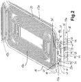
- Fig. 2
- einen vergrößerten Ausschnitt der Darstellung aus
Fig. 1 , - Fig. 3
- eine Seitenansicht eines fertigen Induktionskochfelds mit dem Unterbau gemäß
Fig. 1 unter einer Kochfeldplatte, - Fig. 4
- eine Vergrößerung der elektrischen Anschlussmittel für die Induktionsspulen in einer Ansicht entsprechend
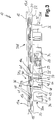
Fig. 1 und - Fig. 5
- eine Unteransicht der elektrischen Anschlussmittel aus
Fig. 4 . - In der
Fig. 1 ist in Schrägansicht von oben ein Unterbau 11 für ein erfindungsgemäßes Induktionskochfeld zu sehen, wie es in derFig. 3 in Seitenansicht komplett dargestellt ist. Der Unterbau 11 weist vier Induktionsspulen 13a bis 13d auf, die aus einem üblichen Spulendraht 14 in mehreren Windungen gewickelt sind. Die Induktionsspulen 13a bis 13d sind einschichtig gewickelt und weisen im Wesentlichen eine rechteckige Außenform mit abgerundeten Ecken auf, was aber nicht zwingend so sein muss. Jede Induktionsspule weist ein inneres Anschlussende 15a bis 15d auf, welches von der innersten Windung aus abgeht und etwas über den äußeren Rand der Induktionsspule übersteht. Ebenso weist sie ein äußeres Anschlussende 16a bis 16d auf, welches direkt von der äußersten Windung abgeht und somit sehr kurz sein kann um über den äußeren Rand der Induktionsspule überzustehen. Auf diese Anschlussenden 15a bis 15d und 16a bis 16d bzw. deren elektrischen Anschluss wird nachfolgend noch näher eingegangen. - Die Induktionsspulen 13a bis 13d sind zwischen oberen Isolatorscheiben 18 und unteren Isolatorscheiben 18, beispielsweise aus Glimmer oder elektrisch isolierendem und/oder thermisch dämmendem Material, angeordnet, wie dies aus dem Stand der Technik bekannt ist. An der Unterseite der unteren Isolatorscheiben 18 sind Ferrite 20 in länglicher bzw. Stabform vorgesehen, wie dies ebenfalls aus dem Stand der Technik bekannt ist. Das innere Anschlussende 15 ist jeweils mit dem Spulendraht 14 von der innersten Spulenwindung abgehend durch die untere Isolatorscheibe 18 geführt und dann zwischen den Ferriten 20 hindurch außerhalb von der jeweiligen Induktionsspule zu einem entsprechenden elektrischen Anschlussmittel 31.
- Die Induktionsspulen 13a bis 13d ruhen also mit ihrem Aufbau auf einem Tragblech 22, welches vorteilhaft großflächig ausgebildet ist und im Wesentlichen die Fläche bzw. Größe des Unterbaus 11 und auch des Induktionskochfelds 10 einnimmt. Anstelle eines Tragblechs 22 aus Metall kann auch ein Kunststoffteil verwendet werden. Das Tragblech weist vier Ausnehmungen 23a bis 23d auf, die jeweils im Bereich der Anschlussenden 15a bis 15d und 16a bis 16d vorgesehen sind.
- Mittels Abstandshaltern 24 ist, wie insbesondere aus der seitlichen Darstellung der
Fig. 3 entnommen werden kann, von unten an dem Tragblech 22 ein Bauteilträger 26 befestigt. Der Bauteilträger 26 kann eine Leiterplatte sein bzw. direkt aufgebrachte Leiterbahnen aufweisen. Alternativ kann es eine Art Träger aus Kunststoff oder anderem isolierten Material sein, auf dem gemäßFig. 3 zahlreiche Funktionseinheiten des Induktionskochfelds 10 angeordnet sind wie ein Lüfter 28 und eine Leistungselektronik 29 mit einem charakteristischen Kühlkörper. Vor allem kann hier auch eine nicht dargestellte elektronische Steuerung als sozusagen Intelligenz für das Induktionskochfeld 10 vorgesehen sein. Mittels Leiterbahnen auf dem Bauteilträger 26 sind sie elektrisch verbunden bzw. kontaktiert. Das Induktionskochfeld 10 weist als Kochfeldfläche eine übliche Kochfeldplatte 10 auf, vorteilhaft aus Glaskeramik. - Für die Induktionsspulen 13a bis 13d sind elektrische Anschlussmittel 31a bis 31d als elektrische Anschlüsse vorgesehen. Für jedes Anschlussmittel 31 bzw. elektrischen Anschluss ist ein aus den
Fig. 4 und 5 besser erkennbarer Halter 33a bis 33d vorgesehen, der jeweils zwei seitliche Halterfüße 34 und 35 aufweist, die einen Querträger 36 tragen. Der Halter 33 ist somit in etwa umgekehrt U-förmig, vorteilhaft besteht er aus isolierendem und stabilem Kunststoff. Unten an den Haltefüßen 34 und 35 sind gemäßFig. 5 Haltezapfen 37 vorgesehen, die in entsprechenden kleinen Löchern im Bauteilträger 26 befestigt werden können. Anstelle der Haltezapfen 37 können die Haltefüße 35 auch von unten durch den Bauteilträger 26 hindurch verschraubt sein. Ebenso können die Haltezapfen 37 für eine Rastwirkung nach Einstecken ausgebildet sein. - Die Halter 33a bis 33d sind auf dem Bauteilträger 26 befestigt und verlaufen durch die vorgenannten Ausnehmungen 23a bis 23d im Tragblech 22 hindurch, so dass sie als Anschlussmöglichkeit bzw. elektrischer Anschluss oberhalb des Tragblechs 22 bzw. etwa auf Höhe der Induktionsspulen 13a bis 13d liegen.
- Die Anschlussmittel 31a bis 31d bzw. die elektrischen Anschlüsse sind sämtlich identisch ausgebildet. An dem Querträger 36 sind Schrauben 39 vorgesehen, die in einem Gewinde im Querträger 36 verlaufen und an denen die Anschlussenden 15a und 16a jeweils mit Kabelschuhen 40 auf bekannte Art und Weise angeschraubt sind. Somit findet der elektrische Anschluss im Sinne der vorliegenden Erfindung etwa auf Höhe der Induktionsspulen 13 statt, da der absolute Höhenversatz zwischen den Induktionsspulen 13 und den in
Fig. 3 erkennbaren Schrauben 39 bzw. Kabelschuhen 40 sehr gering ist und nur wenige Millimeter beträgt. Auf alle Fälle findet der elektrische Anschluss aber über dem Tragblech 22 statt und bildet so einen leicht herzustellenden und vor allem wieder zerstörungsfrei lösbaren Anschluss, beispielsweise für Reparaturzwecke. Alternativ zu den Schrauben 39 könnten auch entsprechend stabile und sichere Steckkontakte oder Klemmkontakte auf etwa dieser Höhe vorgesehen sein. Die Kabelschuhe 40 sind vorteilhaft zwischen Flanken 41 am Querträger 36, die über diesen etwas nach oben stehen, fixiert und vor allem gegen ein Verdrehen beim Ein- und Ausschrauben der Schrauben 39 gesichert. - Die Schrauben 39 drücken gegen die Kabelschuhe 40, wobei die oberen Enden von Bandleitern 42, die an der Unterseite des Querträgers 36 durch Umbiegen anliegen, Gewindemuttern 43 aufweisen, in die die Schrauben 39 eingreifen für eine mechanische Befestigung und eine elektrische Kontaktierung. Am unteren Ende weisen die Bandleiter 42 jeweils einen Basisabschnitt 44 auf, mit dem sie an entsprechenden Kontaktfeldern 46 auf dem Bauteilträger 26 verbunden sind, vorteilhaft verlötet sind. Alternativ können die Bandleiter 42 auch umgebogen sein und auf der Oberseite des Querträgers 36 aufliegen, wobei die Kabelschuhe 40 darauf liegen, so dass die Schrauben 39 die Kabelschuhe 40 direkt gegen die Bandleiter 42 drücken.
- Die elektrische Kontaktierung mittels der Schrauben 39, der Kabelschuhe 40 und der Gewindemuttern 43 an die Induktionsspulen bzw. deren Leiter bildet die eingangs genannten Leistungs-Anschlussmittel, die eben etwa auf Höhe der Induktionsspulen liegen, unter Umständen auch leicht darunter. Für Signal-Anschlüsse, beispielsweise von Anzeigen und/oder Temperatursensoren odgl., können Signal-Anschlussmittel vorgesehen sein in Form der Signalleiter 48, die in einen Basisabschnitt 49 eingegossen sind, der auf dem Bauteilträger 26 aufliegt. Unten können die Signalleiter 48 ein Stück aus dem Basisabschnitt 49 herausstehen und an entsprechende, hier nicht dargestellte Kontaktfelder mit Leiterbahnen auf dem Bauteilträger 26 angeschlossen sein, vorteilhaft verlötet sein. Die Signalleiter 48 verlaufen dabei parallel zueinander von dem Bauteilträger 26 aus senkrecht nach oben. Im oberen Bereich weisen sie, wie
Fig. 5 zeigt, einen Verbindungsabschnitt 50 auf, der sie noch einmal auf exaktem Abstand hält. Des Weiteren kann dieser Verbindungsabschnitt 50 in einen Signalleiterausschnitt 51 im Querträger 36 eingesetzt sein zur örtlich exakten Fixierung der Signalleiter 48. - Die über den Querträger 36 überstehenden oberen Enden der Signalleiter 48 bilden erkennbar einen Anschlussstecker, auf den ein Gegenstecker der vorgenannten Teile wie Temperatursensor odgl. leicht aufgesteckt werden kann. Der Signal-Anschluss ist hier also auch als zerstörungsfrei lösbarer elektrischer Anschluss ausgebildet, nämlich als Steckanschluss. Zur Fixierung der Steckverbindung kann ein Gegenstecker Rasthaken odgl. aufweisen, die den Querträger 36 übergreifen können zur sicheren Kontaktierung.
- Aus der vergrößerten Darstellung der
Fig. 2 ist zu ersehen, dass die Ausnehmungen 23a bis 23d für die Anschlussmittel 31a bis 31d deutlich größer sind, was ein einfacheres Aufsetzen sowie größere Maßtoleranzen ermöglicht. Alternativ können die Anschlussmittel 31a bis 31d bzw. die Halterfüße 34 und 35 samt Querträger 36 durch nur minimal größere Ausnehmungen ragen, so dass sie dadurch gegen seitliches Verkippen gesichert sind.
Claims (10)
- Induktionskochfeld (10) mit- mehreren Induktionsspulen (13a-d),- einer Kochfeldfläche (12) über den Induktionsspulen,- einem flächigen Träger (22) für die Induktionsspulen unter den Induktionsspulen, wobei unter dem Träger weitere Funktionseinheiten wie Leistungselektronik (29), Steuerung oder Lüftermittel (28) für das Induktionskochfeld und die Induktionsspulen vorgesehen sind,- einem elektrischen Anschluss mit Anschlussmitteln (31a-d) für die Induktionsspulen an eine Leistungselektronik (29) und/oder Steuerung,wobei der elektrische Anschluss zerstörungsfrei lösbar ausgebildet ist,
wobei der elektrische Anschluss bzw. die Anschlussmittel (31a-d) auf Höhe der Induktionsspulen (13a-d) angeordnet sind bzw. oberhalb des Trägers (22) angeordnet sind, wobei sowohl die Leistungs-Anschlussmittel (39-44) als Leistungs-Anschluss für eine Leistungselektronik (29) für die Induktionsspulen (13a-d) als auch Signal-Anschlussmittel (48-51) als Signal-Anschluss an eine Steuerung als elektrischer Anschluss jeweils auf der Höhe der Induktionsspulen (13a-d) vorgesehen sind,
dadurch gekennzeichnet, dass- ein Bauteilträger (26) unterhalb des Trägers (22) und parallel dazu vorgesehen ist,- ein Halter (33) für die Leistungs-Anschlussmittel (39-44) und/oder die Signal-Anschlussmittel (48-51) auf dem Bauteilträger (26) befestigt ist,- der Halter (33) für die Leistungs-Anschlussmittel (39-44) und/oder die Signal-Anschlussmittel (48-51) zwei seitliche Halterfüße (34, 35) aufweist und einen zwischen diesen verlaufenden Querträger (36), wobei die Anschlussmittel (31a-d) an dem Querträger (36) befestigt sind. - Induktionskochfeld nach Anspruch 1, dadurch gekennzeichnet, dass der elektrische Anschluss bzw. die Anschlussmittel (31a-d) seitlich neben den Induktionsspulen (13a-d) und mit 0,5 cm bis 5 cm Abstand dazu angeordnet sind.
- Induktionskochfeld nach Anspruch 1 oder 2, dadurch gekennzeichnet, dass von den Induktionsspulen (13a-d) abstehende Anschlussenden (15, 16) zur Befestigung an den Leistungs-Anschlussmitteln (39-44) maximal 5 cm freie Länge von der Induktionsspule (13a-d) weg aufweisen, vorzugsweise maximal 3 cm.
- Induktionskochfeld nach einem der vorhergehenden Ansprüche, dadurch gekennzeichnet, dass der elektrische Anschluss als Leistungs-Anschlussmittel (39-44) und/oder als Signal-Anschlussmittel (48-51) verschraubt ist, wobei vorzugsweise die Leistungs-Anschlussmittel und/oder die Signal-Anschlussmittel als Schraubanschlüsse oder als Schraubklemmen ausgebildet sind.
- Induktionskochfeld nach einem der vorhergehenden Ansprüche, dadurch gekennzeichnet, dass der Bauteilträger (26) zumindest einen Teil der Leistungselektronik (29) und/oder die Steuerung trägt, wobei vorzugsweise der Halter (33) an dem Bauteilträger (26) befestigt ist, von dem Bauteilträger absteht und nach oben geht und durch eine entsprechende Ausnehmung (23) in dem Träger (22) ragt.
- Induktionskochfeld nach Anspruch 5, dadurch gekennzeichnet, dass ein elektrischer Leiter (42) zur Leistungsübertragung von dem Leistungs-Anschlussmittel (39-44) auf Höhe der Induktionsspulen (13a-d) zu dem Bauteilträger (26) darunter frei verläuft, vorzugsweise als breiter flacher Leiter (42), wobei er insbesondere auf dem Bauteilträger (26) mit einer Leiterbahn (46) elektrisch kontaktiert ist.
- Induktionskochfeld nach einem der vorhergehenden Ansprüche, dadurch gekennzeichnet, dass elektrische Signalleiter (48) der Signal-Anschlussmittel (48-51) an die Steuerung aus einem eigenstabilen Material bestehen und mit weniger als 5mm Abstand und parallel zueinander von einem Basisabschnitt (49) auf dem Bauteilträger (26) abstehen und geradlinig mit demselben Abstand nach oben gehen bis auf die Höhe der Induktionsspulen (13a-d).
- Induktionskochfeld nach Anspruch 7, dadurch gekennzeichnet, dass die Signalleiter (48) an dem Querträger (36) befestigt sind, wobei vorzugsweise die Signalleiter (48) durch den Querträger (36) verlaufen und insbesondere mit mindestens 3mm Länge über den Querträger nach oben überstehen.
- Induktionskochfeld nach einem der vorhergehenden Ansprüche, gekennzeichnet durch mehrere Induktionsspulen (13a-d), die eine im Wesentlichen rechteckige Form aufweisen, wobei jeweils zwei Induktionsspulen mit gleich langen Seiten mit einem Abstand von 0,5 cm bis 3 cm zueinander angeordnet sind, und wobei die Leistungs-Anschlussmittel (39-44) für die Induktionsspulen (13a-d) an den jeweils gegenüberliegenden Seiten, mit denen die Induktionsspulen voneinander weg weisen, angeordnet sind.
- Induktionskochfeld nach Anspruch 9, dadurch gekennzeichnet, dass mehrere Paare von gleichen Induktionsspulen (13a-d) auf dem Träger vorgesehen sind nebeneinander, vorzugsweise zwei oder drei Paare, wobei sämtliche Leistungs-Anschlussmittel (39-44) für die Induktionsspulen jeweils an den von der gegenüberliegenden bzw. benachbarten Induktionsspule weg weisenden Seiten angeordnet sind.
Priority Applications (2)
| Application Number | Priority Date | Filing Date | Title |
|---|---|---|---|
| ES14168709T ES2854995T3 (es) | 2014-05-16 | 2014-05-16 | Encimera de cocción de inducción |
| EP14168709.5A EP2945463B1 (de) | 2014-05-16 | 2014-05-16 | Induktionskochfeld |
Applications Claiming Priority (1)
| Application Number | Priority Date | Filing Date | Title |
|---|---|---|---|
| EP14168709.5A EP2945463B1 (de) | 2014-05-16 | 2014-05-16 | Induktionskochfeld |
Publications (2)
| Publication Number | Publication Date |
|---|---|
| EP2945463A1 EP2945463A1 (de) | 2015-11-18 |
| EP2945463B1 true EP2945463B1 (de) | 2020-12-16 |
Family
ID=50721708
Family Applications (1)
| Application Number | Title | Priority Date | Filing Date |
|---|---|---|---|
| EP14168709.5A Active EP2945463B1 (de) | 2014-05-16 | 2014-05-16 | Induktionskochfeld |
Country Status (2)
| Country | Link |
|---|---|
| EP (1) | EP2945463B1 (de) |
| ES (1) | ES2854995T3 (de) |
Cited By (1)
| Publication number | Priority date | Publication date | Assignee | Title |
|---|---|---|---|---|
| EP4503858A4 (de) * | 2022-05-18 | 2025-07-30 | Samsung Electronics Co Ltd | Kochgerät |
Families Citing this family (6)
| Publication number | Priority date | Publication date | Assignee | Title |
|---|---|---|---|---|
| WO2017093173A1 (en) * | 2015-12-01 | 2017-06-08 | Arcelik Anonim Sirketi | An inductive coil unit |
| ES2619110B1 (es) | 2015-12-23 | 2018-04-10 | Bsh Electrodomésticos España, S.A. | Campo de cocción por inducción, y método para poner en funcionamiento un campo de cocción por inducción |
| DE102016212330A1 (de) | 2016-07-06 | 2018-01-11 | E.G.O. Elektro-Gerätebau GmbH | Verfahren zum Betrieb eines Kochfelds und Kochfeld |
| ES2730394T3 (es) | 2016-10-10 | 2019-11-11 | Ego Elektro Geraetebau Gmbh | Método para controlar una encimera de cocción de inducción y encimera de cocción de inducción |
| ES2684168B1 (es) * | 2017-03-30 | 2019-07-29 | Bsh Electrodomesticos Espana Sa | Dispositivo de aparato de cocción |
| EP4015916A1 (de) * | 2020-12-16 | 2022-06-22 | Electrolux Appliances Aktiebolag | Haushaltsgerät und verfahren zum zusammenbau eines haushaltsgeräts |
Family Cites Families (6)
| Publication number | Priority date | Publication date | Assignee | Title |
|---|---|---|---|---|
| JP2004335295A (ja) * | 2003-05-08 | 2004-11-25 | Matsushita Electric Ind Co Ltd | 誘導加熱調理器 |
| DE102006054973A1 (de) * | 2006-11-15 | 2008-05-29 | E.G.O. Elektro-Gerätebau GmbH | Induktive Kochzone, Induktionskochfeld und Ansteuerverfahren |
| DE102007006280A1 (de) | 2007-01-31 | 2008-08-07 | E.G.O. Elektro-Gerätebau GmbH | Verfahren zum Aufbau eines Induktionskochfeldes und Induktionskochfeld |
| FR2971910B1 (fr) * | 2011-02-21 | 2014-07-04 | Fagorbrandt Sas | Foyer de cuisson a induction et table de cuisson a induction associee |
| DE102012101829A1 (de) * | 2012-03-05 | 2013-09-05 | Miele & Cie. Kg | Induktionskochfeld |
| DE102013220286A1 (de) * | 2012-11-14 | 2014-05-15 | BSH Bosch und Siemens Hausgeräte GmbH | Hausgerätevorrichtung |
-
2014
- 2014-05-16 ES ES14168709T patent/ES2854995T3/es active Active
- 2014-05-16 EP EP14168709.5A patent/EP2945463B1/de active Active
Non-Patent Citations (1)
| Title |
|---|
| None * |
Cited By (1)
| Publication number | Priority date | Publication date | Assignee | Title |
|---|---|---|---|---|
| EP4503858A4 (de) * | 2022-05-18 | 2025-07-30 | Samsung Electronics Co Ltd | Kochgerät |
Also Published As
| Publication number | Publication date |
|---|---|
| EP2945463A1 (de) | 2015-11-18 |
| ES2854995T3 (es) | 2021-09-23 |
Similar Documents
| Publication | Publication Date | Title |
|---|---|---|
| EP2945463A1 (de) | Induktionskochfeld | |
| EP3104665B1 (de) | Induktionsheizeinrichtung und induktionskochfeld mit einer solchen induktionsheizeinrichtung | |
| EP3079443A1 (de) | Induktionskochfeld und flexibler träger für ein induktionskochfeld | |
| EP1758206A2 (de) | Vertikale Steckmöglichkeit bei Reihenklemme mit Etagenversatz | |
| DE102014117868A1 (de) | Verbindungsadapter für eine Anschlussklemmenanordnung | |
| EP0113923A2 (de) | Elektrokochplatte | |
| WO2015052117A1 (de) | Elektronische schaltung | |
| DE102011108937A1 (de) | Hochstromkontaktelement für Leiterplatten | |
| EP3963674B1 (de) | Schnittstelle für leiterplatte | |
| DE102015113512B3 (de) | Klemmanordnung und Federkraftklemme | |
| DE202010013449U1 (de) | Fernsteuerbare Steckdose mit guter Wärmeableitungsauswirkung | |
| EP0399105B1 (de) | Elektrokochplatte | |
| DE102015115819A1 (de) | Leiterbrückenelement sowie Bestückungsgurt und Leiterplatten mit einem solchen | |
| WO2022106052A1 (de) | Elektrogerät und anordnung von elektrogeräten | |
| EP2673847B1 (de) | Direktsteckverbinder zur elektrischen direktkontaktierung einer leiterplatte | |
| EP1978598A2 (de) | Anschlussvorrichtung für eine Elektrokochplatte und Elektrokochplatte | |
| EP0895660A1 (de) | Kabelsteckverbinder mit in einem isolationskörper befestigten kontaktbahnen mit lötanschlüssen | |
| DE102012101829A1 (de) | Induktionskochfeld | |
| DE102007025040A1 (de) | Elektrisches Schaltgerät | |
| DE102014103040B4 (de) | Leiterplattenanordnung mit flexiblem Verbindungselement | |
| WO2022242987A1 (de) | Elektrische anordnung mit drosselspule | |
| DE8717004U1 (de) | Einrichtung zur Befestigung von Steckverbindern | |
| DE522904C (de) | Heizkoerper fuer elektrische Heizoefen mit zu beiden Seiten des Heizkoerpers quer zu seiner Laengsrichtung angeordneten Kontaktstiften | |
| DE202011050653U1 (de) | Elektrischer Verbinder | |
| EP2709212A1 (de) | Anordnung zum Verbinden von Leiterplatten |
Legal Events
| Date | Code | Title | Description |
|---|---|---|---|
| PUAI | Public reference made under article 153(3) epc to a published international application that has entered the european phase |
Free format text: ORIGINAL CODE: 0009012 |
|
| AK | Designated contracting states |
Kind code of ref document: A1 Designated state(s): AL AT BE BG CH CY CZ DE DK EE ES FI FR GB GR HR HU IE IS IT LI LT LU LV MC MK MT NL NO PL PT RO RS SE SI SK SM TR |
|
| AX | Request for extension of the european patent |
Extension state: BA ME |
|
| 17P | Request for examination filed |
Effective date: 20160512 |
|
| RBV | Designated contracting states (corrected) |
Designated state(s): AL AT BE BG CH CY CZ DE DK EE ES FI FR GB GR HR HU IE IS IT LI LT LU LV MC MK MT NL NO PL PT RO RS SE SI SK SM TR |
|
| STAA | Information on the status of an ep patent application or granted ep patent |
Free format text: STATUS: EXAMINATION IS IN PROGRESS |
|
| 17Q | First examination report despatched |
Effective date: 20180806 |
|
| GRAP | Despatch of communication of intention to grant a patent |
Free format text: ORIGINAL CODE: EPIDOSNIGR1 |
|
| STAA | Information on the status of an ep patent application or granted ep patent |
Free format text: STATUS: GRANT OF PATENT IS INTENDED |
|
| INTG | Intention to grant announced |
Effective date: 20200729 |
|
| GRAS | Grant fee paid |
Free format text: ORIGINAL CODE: EPIDOSNIGR3 |
|
| GRAA | (expected) grant |
Free format text: ORIGINAL CODE: 0009210 |
|
| STAA | Information on the status of an ep patent application or granted ep patent |
Free format text: STATUS: THE PATENT HAS BEEN GRANTED |
|
| RAP1 | Party data changed (applicant data changed or rights of an application transferred) |
Owner name: E.G.O. ELEKTRO-GERAETEBAU GMBH |
|
| AK | Designated contracting states |
Kind code of ref document: B1 Designated state(s): AL AT BE BG CH CY CZ DE DK EE ES FI FR GB GR HR HU IE IS IT LI LT LU LV MC MK MT NL NO PL PT RO RS SE SI SK SM TR |
|
| REG | Reference to a national code |
Ref country code: GB Ref legal event code: FG4D Free format text: NOT ENGLISH |
|
| REG | Reference to a national code |
Ref country code: DE Ref legal event code: R096 Ref document number: 502014015104 Country of ref document: DE |
|
| REG | Reference to a national code |
Ref country code: IE Ref legal event code: FG4D Free format text: LANGUAGE OF EP DOCUMENT: GERMAN |
|
| REG | Reference to a national code |
Ref country code: AT Ref legal event code: REF Ref document number: 1346759 Country of ref document: AT Kind code of ref document: T Effective date: 20210115 |
|
| PG25 | Lapsed in a contracting state [announced via postgrant information from national office to epo] |
Ref country code: FI Free format text: LAPSE BECAUSE OF FAILURE TO SUBMIT A TRANSLATION OF THE DESCRIPTION OR TO PAY THE FEE WITHIN THE PRESCRIBED TIME-LIMIT Effective date: 20201216 Ref country code: RS Free format text: LAPSE BECAUSE OF FAILURE TO SUBMIT A TRANSLATION OF THE DESCRIPTION OR TO PAY THE FEE WITHIN THE PRESCRIBED TIME-LIMIT Effective date: 20201216 Ref country code: NO Free format text: LAPSE BECAUSE OF FAILURE TO SUBMIT A TRANSLATION OF THE DESCRIPTION OR TO PAY THE FEE WITHIN THE PRESCRIBED TIME-LIMIT Effective date: 20210316 Ref country code: GR Free format text: LAPSE BECAUSE OF FAILURE TO SUBMIT A TRANSLATION OF THE DESCRIPTION OR TO PAY THE FEE WITHIN THE PRESCRIBED TIME-LIMIT Effective date: 20210317 |
|
| REG | Reference to a national code |
Ref country code: NL Ref legal event code: MP Effective date: 20201216 |
|
| PG25 | Lapsed in a contracting state [announced via postgrant information from national office to epo] |
Ref country code: SE Free format text: LAPSE BECAUSE OF FAILURE TO SUBMIT A TRANSLATION OF THE DESCRIPTION OR TO PAY THE FEE WITHIN THE PRESCRIBED TIME-LIMIT Effective date: 20201216 Ref country code: LV Free format text: LAPSE BECAUSE OF FAILURE TO SUBMIT A TRANSLATION OF THE DESCRIPTION OR TO PAY THE FEE WITHIN THE PRESCRIBED TIME-LIMIT Effective date: 20201216 Ref country code: BG Free format text: LAPSE BECAUSE OF FAILURE TO SUBMIT A TRANSLATION OF THE DESCRIPTION OR TO PAY THE FEE WITHIN THE PRESCRIBED TIME-LIMIT Effective date: 20210316 |
|
| PG25 | Lapsed in a contracting state [announced via postgrant information from national office to epo] |
Ref country code: NL Free format text: LAPSE BECAUSE OF FAILURE TO SUBMIT A TRANSLATION OF THE DESCRIPTION OR TO PAY THE FEE WITHIN THE PRESCRIBED TIME-LIMIT Effective date: 20201216 Ref country code: HR Free format text: LAPSE BECAUSE OF FAILURE TO SUBMIT A TRANSLATION OF THE DESCRIPTION OR TO PAY THE FEE WITHIN THE PRESCRIBED TIME-LIMIT Effective date: 20201216 |
|
| REG | Reference to a national code |
Ref country code: LT Ref legal event code: MG9D |
|
| PG25 | Lapsed in a contracting state [announced via postgrant information from national office to epo] |
Ref country code: LT Free format text: LAPSE BECAUSE OF FAILURE TO SUBMIT A TRANSLATION OF THE DESCRIPTION OR TO PAY THE FEE WITHIN THE PRESCRIBED TIME-LIMIT Effective date: 20201216 Ref country code: PT Free format text: LAPSE BECAUSE OF FAILURE TO SUBMIT A TRANSLATION OF THE DESCRIPTION OR TO PAY THE FEE WITHIN THE PRESCRIBED TIME-LIMIT Effective date: 20210416 Ref country code: SK Free format text: LAPSE BECAUSE OF FAILURE TO SUBMIT A TRANSLATION OF THE DESCRIPTION OR TO PAY THE FEE WITHIN THE PRESCRIBED TIME-LIMIT Effective date: 20201216 Ref country code: RO Free format text: LAPSE BECAUSE OF FAILURE TO SUBMIT A TRANSLATION OF THE DESCRIPTION OR TO PAY THE FEE WITHIN THE PRESCRIBED TIME-LIMIT Effective date: 20201216 Ref country code: EE Free format text: LAPSE BECAUSE OF FAILURE TO SUBMIT A TRANSLATION OF THE DESCRIPTION OR TO PAY THE FEE WITHIN THE PRESCRIBED TIME-LIMIT Effective date: 20201216 Ref country code: CZ Free format text: LAPSE BECAUSE OF FAILURE TO SUBMIT A TRANSLATION OF THE DESCRIPTION OR TO PAY THE FEE WITHIN THE PRESCRIBED TIME-LIMIT Effective date: 20201216 Ref country code: SM Free format text: LAPSE BECAUSE OF FAILURE TO SUBMIT A TRANSLATION OF THE DESCRIPTION OR TO PAY THE FEE WITHIN THE PRESCRIBED TIME-LIMIT Effective date: 20201216 |
|
| PG25 | Lapsed in a contracting state [announced via postgrant information from national office to epo] |
Ref country code: PL Free format text: LAPSE BECAUSE OF FAILURE TO SUBMIT A TRANSLATION OF THE DESCRIPTION OR TO PAY THE FEE WITHIN THE PRESCRIBED TIME-LIMIT Effective date: 20201216 |
|
| REG | Reference to a national code |
Ref country code: DE Ref legal event code: R097 Ref document number: 502014015104 Country of ref document: DE |
|
| REG | Reference to a national code |
Ref country code: ES Ref legal event code: FG2A Ref document number: 2854995 Country of ref document: ES Kind code of ref document: T3 Effective date: 20210923 |
|
| PG25 | Lapsed in a contracting state [announced via postgrant information from national office to epo] |
Ref country code: IS Free format text: LAPSE BECAUSE OF FAILURE TO SUBMIT A TRANSLATION OF THE DESCRIPTION OR TO PAY THE FEE WITHIN THE PRESCRIBED TIME-LIMIT Effective date: 20210416 |
|
| PLBE | No opposition filed within time limit |
Free format text: ORIGINAL CODE: 0009261 |
|
| STAA | Information on the status of an ep patent application or granted ep patent |
Free format text: STATUS: NO OPPOSITION FILED WITHIN TIME LIMIT |
|
| PG25 | Lapsed in a contracting state [announced via postgrant information from national office to epo] |
Ref country code: AL Free format text: LAPSE BECAUSE OF FAILURE TO SUBMIT A TRANSLATION OF THE DESCRIPTION OR TO PAY THE FEE WITHIN THE PRESCRIBED TIME-LIMIT Effective date: 20201216 |
|
| 26N | No opposition filed |
Effective date: 20210917 |
|
| PG25 | Lapsed in a contracting state [announced via postgrant information from national office to epo] |
Ref country code: DK Free format text: LAPSE BECAUSE OF FAILURE TO SUBMIT A TRANSLATION OF THE DESCRIPTION OR TO PAY THE FEE WITHIN THE PRESCRIBED TIME-LIMIT Effective date: 20201216 |
|
| REG | Reference to a national code |
Ref country code: CH Ref legal event code: PL |
|
| GBPC | Gb: european patent ceased through non-payment of renewal fee |
Effective date: 20210516 |
|
| PG25 | Lapsed in a contracting state [announced via postgrant information from national office to epo] |
Ref country code: CH Free format text: LAPSE BECAUSE OF NON-PAYMENT OF DUE FEES Effective date: 20210531 Ref country code: MC Free format text: LAPSE BECAUSE OF FAILURE TO SUBMIT A TRANSLATION OF THE DESCRIPTION OR TO PAY THE FEE WITHIN THE PRESCRIBED TIME-LIMIT Effective date: 20201216 Ref country code: LU Free format text: LAPSE BECAUSE OF NON-PAYMENT OF DUE FEES Effective date: 20210516 Ref country code: LI Free format text: LAPSE BECAUSE OF NON-PAYMENT OF DUE FEES Effective date: 20210531 |
|
| REG | Reference to a national code |
Ref country code: BE Ref legal event code: MM Effective date: 20210531 |
|
| PG25 | Lapsed in a contracting state [announced via postgrant information from national office to epo] |
Ref country code: SI Free format text: LAPSE BECAUSE OF FAILURE TO SUBMIT A TRANSLATION OF THE DESCRIPTION OR TO PAY THE FEE WITHIN THE PRESCRIBED TIME-LIMIT Effective date: 20201216 |
|
| PG25 | Lapsed in a contracting state [announced via postgrant information from national office to epo] |
Ref country code: IE Free format text: LAPSE BECAUSE OF NON-PAYMENT OF DUE FEES Effective date: 20210516 Ref country code: GB Free format text: LAPSE BECAUSE OF NON-PAYMENT OF DUE FEES Effective date: 20210516 |
|
| PG25 | Lapsed in a contracting state [announced via postgrant information from national office to epo] |
Ref country code: IS Free format text: LAPSE BECAUSE OF FAILURE TO SUBMIT A TRANSLATION OF THE DESCRIPTION OR TO PAY THE FEE WITHIN THE PRESCRIBED TIME-LIMIT Effective date: 20210416 Ref country code: FR Free format text: LAPSE BECAUSE OF NON-PAYMENT OF DUE FEES Effective date: 20210531 |
|
| REG | Reference to a national code |
Ref country code: AT Ref legal event code: MM01 Ref document number: 1346759 Country of ref document: AT Kind code of ref document: T Effective date: 20210516 |
|
| PG25 | Lapsed in a contracting state [announced via postgrant information from national office to epo] |
Ref country code: BE Free format text: LAPSE BECAUSE OF NON-PAYMENT OF DUE FEES Effective date: 20210531 |
|
| PG25 | Lapsed in a contracting state [announced via postgrant information from national office to epo] |
Ref country code: AT Free format text: LAPSE BECAUSE OF NON-PAYMENT OF DUE FEES Effective date: 20210516 |
|
| PG25 | Lapsed in a contracting state [announced via postgrant information from national office to epo] |
Ref country code: HU Free format text: LAPSE BECAUSE OF FAILURE TO SUBMIT A TRANSLATION OF THE DESCRIPTION OR TO PAY THE FEE WITHIN THE PRESCRIBED TIME-LIMIT; INVALID AB INITIO Effective date: 20140516 |
|
| PG25 | Lapsed in a contracting state [announced via postgrant information from national office to epo] |
Ref country code: CY Free format text: LAPSE BECAUSE OF FAILURE TO SUBMIT A TRANSLATION OF THE DESCRIPTION OR TO PAY THE FEE WITHIN THE PRESCRIBED TIME-LIMIT Effective date: 20201216 |
|
| PG25 | Lapsed in a contracting state [announced via postgrant information from national office to epo] |
Ref country code: MK Free format text: LAPSE BECAUSE OF FAILURE TO SUBMIT A TRANSLATION OF THE DESCRIPTION OR TO PAY THE FEE WITHIN THE PRESCRIBED TIME-LIMIT Effective date: 20201216 |
|
| PGFP | Annual fee paid to national office [announced via postgrant information from national office to epo] |
Ref country code: DE Payment date: 20240517 Year of fee payment: 11 |
|
| PGFP | Annual fee paid to national office [announced via postgrant information from national office to epo] |
Ref country code: ES Payment date: 20240614 Year of fee payment: 11 |
|
| PG25 | Lapsed in a contracting state [announced via postgrant information from national office to epo] |
Ref country code: MT Free format text: LAPSE BECAUSE OF FAILURE TO SUBMIT A TRANSLATION OF THE DESCRIPTION OR TO PAY THE FEE WITHIN THE PRESCRIBED TIME-LIMIT Effective date: 20201216 |
|
| PGFP | Annual fee paid to national office [announced via postgrant information from national office to epo] |
Ref country code: IT Payment date: 20240531 Year of fee payment: 11 |
|
| REG | Reference to a national code |
Ref country code: DE Ref legal event code: R119 Ref document number: 502014015104 Country of ref document: DE |
|
| PG25 | Lapsed in a contracting state [announced via postgrant information from national office to epo] |
Ref country code: TR Free format text: LAPSE BECAUSE OF FAILURE TO SUBMIT A TRANSLATION OF THE DESCRIPTION OR TO PAY THE FEE WITHIN THE PRESCRIBED TIME-LIMIT Effective date: 20201216 |
|
| PG25 | Lapsed in a contracting state [announced via postgrant information from national office to epo] |
Ref country code: DE Free format text: LAPSE BECAUSE OF NON-PAYMENT OF DUE FEES Effective date: 20251202 |
|
| PG25 | Lapsed in a contracting state [announced via postgrant information from national office to epo] |
Ref country code: IT Free format text: LAPSE BECAUSE OF NON-PAYMENT OF DUE FEES Effective date: 20250516 |