EP2942528B1 - Pumpenaggregat mit elektromotor - Google Patents
Pumpenaggregat mit elektromotor Download PDFInfo
- Publication number
- EP2942528B1 EP2942528B1 EP15001105.4A EP15001105A EP2942528B1 EP 2942528 B1 EP2942528 B1 EP 2942528B1 EP 15001105 A EP15001105 A EP 15001105A EP 2942528 B1 EP2942528 B1 EP 2942528B1
- Authority
- EP
- European Patent Office
- Prior art keywords
- pump
- pressure sensor
- electric motor
- pump unit
- housing
- Prior art date
- Legal status (The legal status is an assumption and is not a legal conclusion. Google has not performed a legal analysis and makes no representation as to the accuracy of the status listed.)
- Active
Links
- 239000012530 fluid Substances 0.000 claims description 8
- 230000003068 static effect Effects 0.000 claims description 5
- 230000002706 hydrostatic effect Effects 0.000 claims description 2
- 238000007789 sealing Methods 0.000 claims 1
- 238000009434 installation Methods 0.000 description 3
- 238000003780 insertion Methods 0.000 description 2
- 230000037431 insertion Effects 0.000 description 2
- 238000007726 management method Methods 0.000 description 2
- 230000005540 biological transmission Effects 0.000 description 1
- 238000001816 cooling Methods 0.000 description 1
- 238000011161 development Methods 0.000 description 1
- 230000018109 developmental process Effects 0.000 description 1
- 238000005553 drilling Methods 0.000 description 1
- 238000005461 lubrication Methods 0.000 description 1
Images

Classifications
-
- F—MECHANICAL ENGINEERING; LIGHTING; HEATING; WEAPONS; BLASTING
- F04—POSITIVE - DISPLACEMENT MACHINES FOR LIQUIDS; PUMPS FOR LIQUIDS OR ELASTIC FLUIDS
- F04D—NON-POSITIVE-DISPLACEMENT PUMPS
- F04D29/00—Details, component parts, or accessories
- F04D29/40—Casings; Connections of working fluid
- F04D29/42—Casings; Connections of working fluid for radial or helico-centrifugal pumps
- F04D29/426—Casings; Connections of working fluid for radial or helico-centrifugal pumps especially adapted for liquid pumps
-
- F—MECHANICAL ENGINEERING; LIGHTING; HEATING; WEAPONS; BLASTING
- F04—POSITIVE - DISPLACEMENT MACHINES FOR LIQUIDS; PUMPS FOR LIQUIDS OR ELASTIC FLUIDS
- F04B—POSITIVE-DISPLACEMENT MACHINES FOR LIQUIDS; PUMPS
- F04B17/00—Pumps characterised by combination with, or adaptation to, specific driving engines or motors
- F04B17/03—Pumps characterised by combination with, or adaptation to, specific driving engines or motors driven by electric motors
-
- F—MECHANICAL ENGINEERING; LIGHTING; HEATING; WEAPONS; BLASTING
- F04—POSITIVE - DISPLACEMENT MACHINES FOR LIQUIDS; PUMPS FOR LIQUIDS OR ELASTIC FLUIDS
- F04B—POSITIVE-DISPLACEMENT MACHINES FOR LIQUIDS; PUMPS
- F04B53/00—Component parts, details or accessories not provided for in, or of interest apart from, groups F04B1/00 - F04B23/00 or F04B39/00 - F04B47/00
- F04B53/16—Casings; Cylinders; Cylinder liners or heads; Fluid connections
-
- F—MECHANICAL ENGINEERING; LIGHTING; HEATING; WEAPONS; BLASTING
- F04—POSITIVE - DISPLACEMENT MACHINES FOR LIQUIDS; PUMPS FOR LIQUIDS OR ELASTIC FLUIDS
- F04B—POSITIVE-DISPLACEMENT MACHINES FOR LIQUIDS; PUMPS
- F04B53/00—Component parts, details or accessories not provided for in, or of interest apart from, groups F04B1/00 - F04B23/00 or F04B39/00 - F04B47/00
- F04B53/22—Arrangements for enabling ready assembly or disassembly
-
- F—MECHANICAL ENGINEERING; LIGHTING; HEATING; WEAPONS; BLASTING
- F04—POSITIVE - DISPLACEMENT MACHINES FOR LIQUIDS; PUMPS FOR LIQUIDS OR ELASTIC FLUIDS
- F04D—NON-POSITIVE-DISPLACEMENT PUMPS
- F04D13/00—Pumping installations or systems
- F04D13/02—Units comprising pumps and their driving means
- F04D13/06—Units comprising pumps and their driving means the pump being electrically driven
- F04D13/0693—Details or arrangements of the wiring
-
- F—MECHANICAL ENGINEERING; LIGHTING; HEATING; WEAPONS; BLASTING
- F04—POSITIVE - DISPLACEMENT MACHINES FOR LIQUIDS; PUMPS FOR LIQUIDS OR ELASTIC FLUIDS
- F04D—NON-POSITIVE-DISPLACEMENT PUMPS
- F04D15/00—Control, e.g. regulation, of pumps, pumping installations or systems
- F04D15/0088—Testing machines
-
- F—MECHANICAL ENGINEERING; LIGHTING; HEATING; WEAPONS; BLASTING
- F04—POSITIVE - DISPLACEMENT MACHINES FOR LIQUIDS; PUMPS FOR LIQUIDS OR ELASTIC FLUIDS
- F04D—NON-POSITIVE-DISPLACEMENT PUMPS
- F04D29/00—Details, component parts, or accessories
- F04D29/60—Mounting; Assembling; Disassembling
- F04D29/605—Mounting; Assembling; Disassembling specially adapted for liquid pumps
- F04D29/606—Mounting in cavities
-
- G—PHYSICS
- G01—MEASURING; TESTING
- G01L—MEASURING FORCE, STRESS, TORQUE, WORK, MECHANICAL POWER, MECHANICAL EFFICIENCY, OR FLUID PRESSURE
- G01L23/00—Devices or apparatus for measuring or indicating or recording rapid changes, such as oscillations, in the pressure of steam, gas, or liquid; Indicators for determining work or energy of steam, internal-combustion, or other fluid-pressure engines from the condition of the working fluid
- G01L23/08—Devices or apparatus for measuring or indicating or recording rapid changes, such as oscillations, in the pressure of steam, gas, or liquid; Indicators for determining work or energy of steam, internal-combustion, or other fluid-pressure engines from the condition of the working fluid operated electrically
Definitions
- the invention relates to a pump unit with an electric motor according to the preamble of the first claim.
- Pump units with an electric motor are known, for example from the publications US5778671A . DE 603 09 123 T2 . US 4470427 A ,
- the pump unit is equipped with an electrical pressure sensor, which is connected to a plug connection already present for the electric motor, that no electrical lines outside the housing of the electric motor or the connector must be laid. Also connected to the pump unit hydraulic throttle is arranged in the housing of the pump unit.
- the pump unit should be able to be easily inserted into a higher-level unit, which contains the required fluidic lines, by insertion.
- the pressure sensor is arranged in the housing of the plug connection or in a part of the pump housing, so that the electrical lines of the pressure sensor can be laid inside these housings and do not complicate the insertion of the pump unit in the parent unit. Fluidically, the pressure sensor is connected by a preferably parallel to the axis of the pump unit running bore with one of the two connecting lines, namely the pressure line.
- Said bore and the hydraulic part of the pressure sensor are sealed together by a seal to the housing of the connector and the environment.
- the electric motor does not run in the working fluid of the pump, but dry and is therefore sealed by a shaft seal and a static seal to the pump.
- the throttle fulfills the purpose that the delivery rate of the pump depends primarily on the speed of the electric motor and the pressure difference between the lines (5) and (6), and much less on the temperature of the working fluid.
- the pump unit according to the invention finds application in vehicle transmissions and vehicle engines for the speed-independent supply of these units with working fluid, preferably with oil, for lubrication, cooling and actuation of, for example, clutches and camshaft adjusting devices.
- a pump unit (1) consisting of a hydrostatic pump (2) and an electric motor (3), via a plug connection (4) electrically with an electrical control and fluidly via a first line (5) and a second line (6) with a consumer or a plurality connected by consumers.
- the second line (6) is connected by at least one bore (7) with a pressure sensor (8) having a common housing (9) with the connector (4), or, as in Fig. 2 shown with a part of the motor housing (15) has a common housing. This ensures that the electrical lines from the connector (4) to the pressure sensor does not have to be routed outside of the housing (15) or (10).
- the delivery rate of the pump primarily depends on the speed of the electric motor and the pressure difference between the lines (5) and (6), and much less of the temperature of the working fluid, the first line (5) and the second line (6) Pump within the pump housing (10) through a throttle (14).
- the throttle is part of the pump set, so that the operation of the throttle is detected during a test of the pump set before installation.
Landscapes
- Engineering & Computer Science (AREA)
- Mechanical Engineering (AREA)
- General Engineering & Computer Science (AREA)
- Chemical & Material Sciences (AREA)
- Combustion & Propulsion (AREA)
- Physics & Mathematics (AREA)
- General Physics & Mathematics (AREA)
- Details And Applications Of Rotary Liquid Pumps (AREA)
- Details Of Reciprocating Pumps (AREA)
- Measuring Fluid Pressure (AREA)
Description
- Die Erfindung betrifft ein Pumpenaggregat mit einem Elektromotor entsprechend dem Oberbegriff des ersten Patentanspruchs. Pumpenaggregate mit einem Elektromotor sind bekannt, zum Beispiel aus den Druckschriften
US5778671A ,DE 603 09 123 T2 ,US 4470427 A . -
DE 10 2012 202162 A1 offenbart ein Pumpenaggregat gemäß dem Oberbegriff des Anspruchs 1. - Das Pumpenaggregat ist mit einem elektrischen Drucksensor ausgerüstet, der so mit einer für den Elektromotor ohnehin vorhandenen Steckverbindung verbunden ist, dass keine elektrischen Leitungen außerhalb der Gehäuse des Elektromotors oder der Steckverbindung verlegt werden müssen. Auch eine an das Pumpenaggregat angeschlossene hydraulische Drossel ist in dem Gehäuse des Pumpenaggregats angeordnet.
- Aufgabengemäß soll das Pumpenaggregat leicht in ein übergeordnetes Aggregat, das die erforderlichen fluidischen Leitungen enthält, durch Einschieben zu fügen sein.
- Die Aufgaben werden durch die Merkmale des ersten Patentanspruchs gelöst, in Verbindung mit vorteilhaften Weiterbildungen, die in den Unteransprüchen angegeben sind.
- Der Drucksensor ist im Gehäuse der Steckverbindung oder in einem Teil des Pumpengehäuses angeordnet, damit können die elektrischen Leitungen des Drucksensors im Inneren dieser Gehäuse verlegt werden und erschweren das Einschieben des Pumpenaggregats in das übergeordnete Aggregat nicht. Fluidisch ist der Drucksensor durch eine vorzugsweise parallel zur Achse des Pumpenaggregats verlaufende Bohrung mit einer der beiden Anschlussleitungen, nämlich der Druckleitung, verbunden.
- Die genannte Bohrung und der hydraulische Teil des Drucksensors sind gemeinsam durch eine Dichtung zum Gehäuse der Steckverbindung und zur Umgebung abgedichtet.
- Der Elektromotor läuft nicht im Arbeitsfluid der Pumpe, sondern trocken und wird deshalb durch eine Wellendichtung und eine statische Dichtung zur Pumpe hin abgedichtet.
- Damit wird erreicht, dass die elektrischen Leitungen des Aggregats nicht abgedichtet werden müssen.
- Zur weiteren Vereinfachung des Einbaus des Pumpenaggregats in das übergeordnete Aggregat wird eine zusätzlich erforderliche hydraulische Drossel zwischen den beiden an die Pumpe angeschlossenen Leitungen im Gehäuse der Pumpe angeordnet. Damit ist es nicht erforderlich, diese Drossel mit zusätzlichen Bohrungen anzuschließen, und bei dem Test des Pumpenaggregats vor dem Einbau ist die Drossel schon mit der Pumpe verbunden und die Pumpe wird mit der Drossel zusammen getestet.
- Die Drossel erfüllt den Zweck, die Fördermenge der Pumpe vorrangig von der Drehzahl des Elektromotors und der Druckdifferenz zwischen den Leitungen (5) und (6) abhängt, und erheblich weniger von der Temperatur des Arbeitsfluids.
- Das erfindungsgemäße Pumpenaggregat findet Anwendung in Fahrzeuggetrieben und Fahrzeugmotoren zur drehzahlunabhängigen Versorgung dieser Aggregate mit Arbeitsfluid, vorzugsweise mit Öl, zur Schmierung, Kühlung und Betätigung zum Beispiel von Kupplungen und Nockenwellenverstelleinrichtungen.
- Bilder:
-
Fig. 1 stellt das Pumpenaggregat mit einer Anordnung des Drucksensors im Steckergehäuse dar -
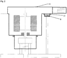
Fig. 2 stellt das Pumpenaggregat mit einer Anordnung des Drucksensors im Motorgehäuse dar - Ein Pumpenaggregat (1) gemäß
Fig. 1 , bestehend aus einer hydrostatischen Pumpe (2) und einem Elektromotor (3), ist über eine Steckverbindung (4) elektrisch mit einer elektrischen Steuerung und fluidisch über eine ersten Leitung (5) und eine zweiten Leitung (6) mit einem Verbraucher oder einer Mehrzahl von Verbrauchern verbunden. - Die zweite Leitung (6) ist durch mindestens eine Bohrung (7) mit einem Drucksensor (8) verbunden, der mit der Steckverbindung (4) ein gemeinsames Gehäuse (9) aufweist, oder, wie in
Fig. 2 gezeigt, mit einem Teil des Motorgehäuses (15) ein gemeinsames Gehäuse aufweist. Dadurch wird erreicht, dass die elektrischen Leitungen von der Steckverbindung (4) zu dem Drucksensor nicht außerhalb des Gehäuses (15) oder (10) verlegt werden müssen. - Die Abdichtung für das Arbeitsfluid der Pumpe (2) zur Umgebung hin erfolgt zwischen der Pumpe (2) und dem Elektromotor (3) einerseits und am Drucksensor (8) andererseits derart, dass alle elektrischen Leitungen zum Elektromotor und zum Drucksensor nicht von dem Arbeitsfluid benetzt werden. Dazu dichten eine Wellendichtung (11) und eine statische Dichtung (12) die Pumpe (2) gegen den Elektromotor (3) ab, und eine statische Dichtung (13) dichtet die Bohrung (7) und den benetzten Teil des Drucksensors (8) gegen den elektrischen Teil des Drucksensors und die Umgebung ab.
- Damit die Fördermenge der Pumpe vorrangig von der Drehzahl des Elektromotors und der Druckdifferenz zwischen den Leitungen (5) und (6) abhängt, und erheblich weniger von der Temperatur des Arbeitsfluids, sind die erste Leitung (5) und die zweite Leitung (6) zur Pumpe innerhalb des Pumpengehäuses (10) durch eine Drossel (14) verbunden. Die Drossel ist Teil des Pumpenaggregats, damit bei einem Test des Pumpenaggregats vor dem Einbau die Arbeitsweise der Drossel mit erfasst wird.
-
- 1.
- Pumpenaggregat
- 2.
- Pumpe
- 3.
- Elektromotor
- 4.
- Steckverbindung
- 5.
- Leitung
- 6.
- Leitung
- 7.
- Bohrung
- 8.
- Drucksensor
- 9.
- Gehäuse (Stecker)
- 10.
- Pumpengehäuse
- 11.
- Wellendichtung
- 12.
- Dichtung
- 13.
- Dichtung
- 14.
- Drossel
- 15.
- Motorgehäuse
Claims (4)
- Ein Pumpenaggregat (1) mit einer hydrostatischen Pumpe (2), einem Elektromotor (3), einem Drucksensor (8), einer Drossel (14) und einer Steckverbindung (4) ist elektrisch über die Steckverbindung (4) mit einer elektrischen Steuerung und fluidisch mit einer ersten Leitung (5) und einer zweiten Leitung (6) mit einem Verbraucher oder einer Mehrzahl von Verbrauchern verbindbar, wobei die zweite Leitung (6) durch mindestens eine Bohrung (7) mit dem Drucksensor (8) verbindbar ist, der mit einem elektrische Bauteile und elektrische Leitungen enthaltenden Gehäuse des Pumpenaggregats (1) ein gemeinsames Gehäuse aufweist, und wobei die erste Leitung (5) und die zweite Leitung (6) zur Pumpe innerhalb des Pumpengehäuses (10) durch die Drossel (14) verbindbar sind,
dadurch gekennzeichnet, dass
das Pumpenaggregat (1) in ein übergeordnetes Aggregat, das die erste und die zweite Leitungen (5, 6) enthält, einschiebbar ist. - Pumpenaggregat nach Anspruch 1, dadurch gekennzeichnet, dass die Abdichtung für das Arbeitsfluid der Pumpe (2) zur Umgebung hin zwischen der Pumpe (2) und dem Elektromotor (3) einerseits und am Drucksensor (8) andererseits so erfolgt, dass alle elektrischen Leitungen zum Elektromotor und zum Drucksensor nicht von dem Arbeitsfluid benetzt werden.
- Pumpenaggregat nach einem der Ansprüche 1 bis 2, dadurch gekennzeichnet, dass eine Wellendichtung (11) und eine statische Dichtung (12) die Pumpe (2) gegen den Elektromotor (3) abdichten.
- Pumpenaggregat nach einem der Ansprüche 1 bis 3, dadurch gekennzeichnet, dass eine statische Dichtung (13) die Bohrung (7) und den benetzten Teil des Drucksensors (8) gegen den elektrischen Teil des Drucksensors, das Innere des Gehäuses (9) oder des Gehäuses (15) und die Umgebung abdichtet.
Applications Claiming Priority (1)
| Application Number | Priority Date | Filing Date | Title |
|---|---|---|---|
| DE102014006556.1A DE102014006556B3 (de) | 2014-05-06 | 2014-05-06 | Pumpenaggregat mit Elektromotor |
Publications (2)
| Publication Number | Publication Date |
|---|---|
| EP2942528A1 EP2942528A1 (de) | 2015-11-11 |
| EP2942528B1 true EP2942528B1 (de) | 2019-10-09 |
Family
ID=52430485
Family Applications (1)
| Application Number | Title | Priority Date | Filing Date |
|---|---|---|---|
| EP15001105.4A Active EP2942528B1 (de) | 2014-05-06 | 2015-04-16 | Pumpenaggregat mit elektromotor |
Country Status (3)
| Country | Link |
|---|---|
| EP (1) | EP2942528B1 (de) |
| CN (1) | CN105090050B (de) |
| DE (1) | DE102014006556B3 (de) |
Families Citing this family (12)
| Publication number | Priority date | Publication date | Assignee | Title |
|---|---|---|---|---|
| DE102014014508B3 (de) * | 2014-10-06 | 2015-06-25 | Thomas Magnete Gmbh | Pumpenaggregat |
| DE102015214678A1 (de) * | 2015-07-31 | 2017-02-02 | Brose Fahrzeugteile GmbH & Co. Kommanditgesellschaft, Würzburg | Elektromotorische Pumpe |
| DE102015010728A1 (de) | 2015-08-17 | 2017-02-23 | Thomas Magnete Gmbh | Motorpumpenaggregat |
| DE102015014224B4 (de) | 2015-11-04 | 2019-03-07 | Thomas Magnete Gmbh | Motorpumpenaggregat |
| DE102017003438B3 (de) | 2017-04-08 | 2018-09-20 | Thomas Magnete Gmbh | Pumpenbaugruppe und Verfahren zum Betrieb der Pumpenbaugruppe |
| DE102018124222A1 (de) | 2018-04-10 | 2019-10-10 | Schaeffler Technologies AG & Co. KG | Elektromotorischer Pumpenaktor sowie Verfahren zu dessen Herstellung und Kupplung umfassend einen solchen elektromotorischen Pumpenaktor |
| DE202018102829U1 (de) | 2018-05-22 | 2019-08-26 | Thomas Magnete Gmbh | Elektrohydraulisches Motorpumpenaggregat |
| DE202018102835U1 (de) | 2018-05-22 | 2019-08-26 | Thomas Magnete Gmbh | Elektrohydraulisches Motorpumpenaggregat mit Wellendichtring |
| DE102018112184A1 (de) | 2018-05-22 | 2019-11-28 | Thomas Magnete Gmbh | Anschlusselement einer Fluidförderpumpe |
| DE202018102834U1 (de) | 2018-05-22 | 2019-08-26 | Thomas Magnete Gmbh | Elektrohydraulisches Motorpumpenaggregat |
| DE202018102832U1 (de) | 2018-05-22 | 2019-08-26 | Thomas Magnete Gmbh | Elektromotor |
| CN112727813B (zh) * | 2020-11-19 | 2022-07-22 | 宣化钢铁集团有限责任公司 | 一种平行作业泵组及使用方法 |
Citations (3)
| Publication number | Priority date | Publication date | Assignee | Title |
|---|---|---|---|---|
| US5135031A (en) * | 1989-09-25 | 1992-08-04 | Vickers, Incorporated | Power transmission |
| DE102007059240A1 (de) * | 2007-12-07 | 2009-06-10 | Thomas Magnete Gmbh | Membranpumpe |
| DE102012202162A1 (de) * | 2011-02-23 | 2012-08-23 | Schaeffler Technologies AG & Co. KG | Hydraulische Einrichtung zur Betätigung einer Kupplung |
Family Cites Families (10)
| Publication number | Priority date | Publication date | Assignee | Title |
|---|---|---|---|---|
| FR2508112B1 (fr) * | 1981-06-19 | 1986-05-02 | Citroen Sa | Regulateur de pompe par etranglement a l'aspiration avec limiteur de pression incorpore |
| US5778671A (en) * | 1996-09-13 | 1998-07-14 | Vickers, Inc. | Electrohydraulic system and apparatus with bidirectional electric-motor/hydraulic-pump unit |
| DE20022192U1 (de) * | 1999-08-02 | 2001-06-07 | Wilo Gmbh | Kombi-Meßfühler |
| DE20013779U1 (de) * | 2000-08-07 | 2000-11-23 | Ashauer, Ernst, Dipl.-Ing., 69469 Weinheim | Tauchpumpenanordnung |
| DE10039917A1 (de) * | 2000-08-16 | 2002-02-28 | Ksb Ag | Verfahren und Vorrichtung zur Ermittlung der Fördermenge einer Kreiselpumpe |
| DE10064708A1 (de) * | 2000-12-22 | 2002-07-11 | Grundfos As | Hauswasserwerk |
| DE10249128A1 (de) * | 2002-10-22 | 2004-06-03 | Wilo Ag | Pumpe mit Verbindungsleitungen zu Messstellen |
| ITPD20020330A1 (it) * | 2002-12-20 | 2004-06-21 | Dab Pumps Spa | Dispositivo per l'azionamento di elettropompe |
| DE10354148A1 (de) * | 2003-11-19 | 2005-06-30 | Aweco Appliance Systems Gmbh & Co. Kg | Pumpe zur Förderung von Flüssigkeiten mit einer Aufnahme für eine Drucküberwachungsvorrichtung |
| DE102009005154A1 (de) * | 2009-01-15 | 2010-07-22 | Wilo Se | Vorrichtung zur Verbindung einer elektromotorischen Antriebseinheit mit einer Pumpeneinheit |
-
2014
- 2014-05-06 DE DE102014006556.1A patent/DE102014006556B3/de not_active Expired - Fee Related
-
2015
- 2015-04-16 EP EP15001105.4A patent/EP2942528B1/de active Active
- 2015-05-06 CN CN201510226157.0A patent/CN105090050B/zh not_active Expired - Fee Related
Patent Citations (3)
| Publication number | Priority date | Publication date | Assignee | Title |
|---|---|---|---|---|
| US5135031A (en) * | 1989-09-25 | 1992-08-04 | Vickers, Incorporated | Power transmission |
| DE102007059240A1 (de) * | 2007-12-07 | 2009-06-10 | Thomas Magnete Gmbh | Membranpumpe |
| DE102012202162A1 (de) * | 2011-02-23 | 2012-08-23 | Schaeffler Technologies AG & Co. KG | Hydraulische Einrichtung zur Betätigung einer Kupplung |
Also Published As
| Publication number | Publication date |
|---|---|
| CN105090050B (zh) | 2017-10-03 |
| CN105090050A (zh) | 2015-11-25 |
| EP2942528A1 (de) | 2015-11-11 |
| DE102014006556B3 (de) | 2015-02-19 |
Similar Documents
| Publication | Publication Date | Title |
|---|---|---|
| DE102014006556B3 (de) | Pumpenaggregat mit Elektromotor | |
| EP2126416B1 (de) | Getriebe mit ölkreislauf-verrohrung und getriebe- baureihe | |
| EP2129940B1 (de) | Getriebe mit schmierölpumpe und getriebe-baureihe | |
| EP3183458B1 (de) | Fluidbeaufschlagungsvorrichtung für ein getriebe für ein kraftfahrzeug | |
| EP3250844B1 (de) | Dichtungsanordnung für ein getriebe, insbesondere für die abtriebswelle eines getriebes, und getriebe mit dichtungsanordnung | |
| DE202018102845U1 (de) | Verbinder für hydrodynamische Anwendungen, der mit wenigstens einem Detektionssensor ausgestattet ist | |
| DE102008057455A1 (de) | Hydraulische Versorgungseinheit | |
| WO2017050402A1 (de) | Betriebsmittelsystem für einen kraftfahrzeugantriebsstrang | |
| DE102015220535A1 (de) | Hydrauliksystem zur Kühlung eines Automatikgetriebes | |
| DE102018124112A1 (de) | Kugelventilgeometrie und dynamische Dichtungsanordnung | |
| DE102008033602B4 (de) | Spindelmotor | |
| DE102005053772B4 (de) | Getriebe | |
| DE102007043016A1 (de) | Antriebsanordnung mit einem Verbrennungsmotor und einer Elektromaschine | |
| DE102016102535A1 (de) | Verbindungshülse | |
| DE102018221052A1 (de) | Ölfiltermodul | |
| DE102015014270B4 (de) | Kraftstoffsystem für einen Verbrennungsmotor mit Leckagereduzierung | |
| WO2021105080A1 (de) | Getriebeeinrichtung für ein elektrisch antreibbares fahrzeug, antriebseinrichtung für ein elektrisch antreibbares fahrzeug und fahrzeug | |
| EP2175341B1 (de) | Thermostatventil | |
| DE102014118702B4 (de) | Kurbelwelle und Kurbelwellenanordnung | |
| DE102015216980A1 (de) | Aktuator mit Sensor | |
| DE112017004504B4 (de) | Hydraulisch betätigtes differential | |
| DE102015014224A1 (de) | Motorpumpenaggregat | |
| EP3337978B1 (de) | Motorpumpenaggregat | |
| DE102014106394A1 (de) | Getriebe für ein Kraftfahrzeug | |
| DE102005015483A1 (de) | Verbindungsleitung für ein Antriebsaggregat eines Kraftfahrzeugs |
Legal Events
| Date | Code | Title | Description |
|---|---|---|---|
| PUAI | Public reference made under article 153(3) epc to a published international application that has entered the european phase |
Free format text: ORIGINAL CODE: 0009012 |
|
| AK | Designated contracting states |
Kind code of ref document: A1 Designated state(s): AL AT BE BG CH CY CZ DE DK EE ES FI FR GB GR HR HU IE IS IT LI LT LU LV MC MK MT NL NO PL PT RO RS SE SI SK SM TR |
|
| AX | Request for extension of the european patent |
Extension state: BA ME |
|
| 17P | Request for examination filed |
Effective date: 20151203 |
|
| RBV | Designated contracting states (corrected) |
Designated state(s): AL AT BE BG CH CY CZ DE DK EE ES FI FR GB GR HR HU IE IS IT LI LT LU LV MC MK MT NL NO PL PT RO RS SE SI SK SM TR |
|
| RAP1 | Party data changed (applicant data changed or rights of an application transferred) |
Owner name: THOMAS MAGNETE GMBH |
|
| STAA | Information on the status of an ep patent application or granted ep patent |
Free format text: STATUS: EXAMINATION IS IN PROGRESS |
|
| 17Q | First examination report despatched |
Effective date: 20180126 |
|
| REG | Reference to a national code |
Ref country code: DE Ref legal event code: R079 Ref document number: 502015010554 Country of ref document: DE Free format text: PREVIOUS MAIN CLASS: F04D0015000000 Ipc: F04D0029600000 |
|
| GRAP | Despatch of communication of intention to grant a patent |
Free format text: ORIGINAL CODE: EPIDOSNIGR1 |
|
| STAA | Information on the status of an ep patent application or granted ep patent |
Free format text: STATUS: GRANT OF PATENT IS INTENDED |
|
| INTG | Intention to grant announced |
Effective date: 20190705 |
|
| RIC1 | Information provided on ipc code assigned before grant |
Ipc: F04B 53/22 20060101ALI20190624BHEP Ipc: F04D 15/00 20060101ALI20190624BHEP Ipc: F04D 29/60 20060101AFI20190624BHEP Ipc: F04D 13/06 20060101ALI20190624BHEP Ipc: F04B 53/16 20060101ALI20190624BHEP Ipc: F04D 29/42 20060101ALI20190624BHEP Ipc: G01L 23/08 20060101ALI20190624BHEP Ipc: F04B 17/03 20060101ALI20190624BHEP |
|
| GRAS | Grant fee paid |
Free format text: ORIGINAL CODE: EPIDOSNIGR3 |
|
| GRAA | (expected) grant |
Free format text: ORIGINAL CODE: 0009210 |
|
| STAA | Information on the status of an ep patent application or granted ep patent |
Free format text: STATUS: THE PATENT HAS BEEN GRANTED |
|
| AK | Designated contracting states |
Kind code of ref document: B1 Designated state(s): AL AT BE BG CH CY CZ DE DK EE ES FI FR GB GR HR HU IE IS IT LI LT LU LV MC MK MT NL NO PL PT RO RS SE SI SK SM TR |
|
| REG | Reference to a national code |
Ref country code: GB Ref legal event code: FG4D Free format text: NOT ENGLISH |
|
| REG | Reference to a national code |
Ref country code: CH Ref legal event code: EP |
|
| REG | Reference to a national code |
Ref country code: DE Ref legal event code: R096 Ref document number: 502015010554 Country of ref document: DE |
|
| REG | Reference to a national code |
Ref country code: IE Ref legal event code: FG4D Free format text: LANGUAGE OF EP DOCUMENT: GERMAN |
|
| REG | Reference to a national code |
Ref country code: AT Ref legal event code: REF Ref document number: 1189155 Country of ref document: AT Kind code of ref document: T Effective date: 20191115 |
|
| REG | Reference to a national code |
Ref country code: NL Ref legal event code: MP Effective date: 20191009 |
|
| REG | Reference to a national code |
Ref country code: LT Ref legal event code: MG4D |
|
| PG25 | Lapsed in a contracting state [announced via postgrant information from national office to epo] |
Ref country code: LV Free format text: LAPSE BECAUSE OF FAILURE TO SUBMIT A TRANSLATION OF THE DESCRIPTION OR TO PAY THE FEE WITHIN THE PRESCRIBED TIME-LIMIT Effective date: 20191009 Ref country code: NL Free format text: LAPSE BECAUSE OF FAILURE TO SUBMIT A TRANSLATION OF THE DESCRIPTION OR TO PAY THE FEE WITHIN THE PRESCRIBED TIME-LIMIT Effective date: 20191009 Ref country code: ES Free format text: LAPSE BECAUSE OF FAILURE TO SUBMIT A TRANSLATION OF THE DESCRIPTION OR TO PAY THE FEE WITHIN THE PRESCRIBED TIME-LIMIT Effective date: 20191009 Ref country code: PL Free format text: LAPSE BECAUSE OF FAILURE TO SUBMIT A TRANSLATION OF THE DESCRIPTION OR TO PAY THE FEE WITHIN THE PRESCRIBED TIME-LIMIT Effective date: 20191009 Ref country code: BG Free format text: LAPSE BECAUSE OF FAILURE TO SUBMIT A TRANSLATION OF THE DESCRIPTION OR TO PAY THE FEE WITHIN THE PRESCRIBED TIME-LIMIT Effective date: 20200109 Ref country code: NO Free format text: LAPSE BECAUSE OF FAILURE TO SUBMIT A TRANSLATION OF THE DESCRIPTION OR TO PAY THE FEE WITHIN THE PRESCRIBED TIME-LIMIT Effective date: 20200109 Ref country code: SE Free format text: LAPSE BECAUSE OF FAILURE TO SUBMIT A TRANSLATION OF THE DESCRIPTION OR TO PAY THE FEE WITHIN THE PRESCRIBED TIME-LIMIT Effective date: 20191009 Ref country code: FI Free format text: LAPSE BECAUSE OF FAILURE TO SUBMIT A TRANSLATION OF THE DESCRIPTION OR TO PAY THE FEE WITHIN THE PRESCRIBED TIME-LIMIT Effective date: 20191009 Ref country code: GR Free format text: LAPSE BECAUSE OF FAILURE TO SUBMIT A TRANSLATION OF THE DESCRIPTION OR TO PAY THE FEE WITHIN THE PRESCRIBED TIME-LIMIT Effective date: 20200110 Ref country code: LT Free format text: LAPSE BECAUSE OF FAILURE TO SUBMIT A TRANSLATION OF THE DESCRIPTION OR TO PAY THE FEE WITHIN THE PRESCRIBED TIME-LIMIT Effective date: 20191009 Ref country code: PT Free format text: LAPSE BECAUSE OF FAILURE TO SUBMIT A TRANSLATION OF THE DESCRIPTION OR TO PAY THE FEE WITHIN THE PRESCRIBED TIME-LIMIT Effective date: 20200210 |
|
| PG25 | Lapsed in a contracting state [announced via postgrant information from national office to epo] |
Ref country code: HR Free format text: LAPSE BECAUSE OF FAILURE TO SUBMIT A TRANSLATION OF THE DESCRIPTION OR TO PAY THE FEE WITHIN THE PRESCRIBED TIME-LIMIT Effective date: 20191009 Ref country code: RS Free format text: LAPSE BECAUSE OF FAILURE TO SUBMIT A TRANSLATION OF THE DESCRIPTION OR TO PAY THE FEE WITHIN THE PRESCRIBED TIME-LIMIT Effective date: 20191009 Ref country code: IS Free format text: LAPSE BECAUSE OF FAILURE TO SUBMIT A TRANSLATION OF THE DESCRIPTION OR TO PAY THE FEE WITHIN THE PRESCRIBED TIME-LIMIT Effective date: 20200224 |
|
| PG25 | Lapsed in a contracting state [announced via postgrant information from national office to epo] |
Ref country code: AL Free format text: LAPSE BECAUSE OF FAILURE TO SUBMIT A TRANSLATION OF THE DESCRIPTION OR TO PAY THE FEE WITHIN THE PRESCRIBED TIME-LIMIT Effective date: 20191009 |
|
| REG | Reference to a national code |
Ref country code: DE Ref legal event code: R097 Ref document number: 502015010554 Country of ref document: DE |
|
| PG2D | Information on lapse in contracting state deleted |
Ref country code: IS |
|
| PG25 | Lapsed in a contracting state [announced via postgrant information from national office to epo] |
Ref country code: CZ Free format text: LAPSE BECAUSE OF FAILURE TO SUBMIT A TRANSLATION OF THE DESCRIPTION OR TO PAY THE FEE WITHIN THE PRESCRIBED TIME-LIMIT Effective date: 20191009 Ref country code: RO Free format text: LAPSE BECAUSE OF FAILURE TO SUBMIT A TRANSLATION OF THE DESCRIPTION OR TO PAY THE FEE WITHIN THE PRESCRIBED TIME-LIMIT Effective date: 20191009 Ref country code: EE Free format text: LAPSE BECAUSE OF FAILURE TO SUBMIT A TRANSLATION OF THE DESCRIPTION OR TO PAY THE FEE WITHIN THE PRESCRIBED TIME-LIMIT Effective date: 20191009 Ref country code: DK Free format text: LAPSE BECAUSE OF FAILURE TO SUBMIT A TRANSLATION OF THE DESCRIPTION OR TO PAY THE FEE WITHIN THE PRESCRIBED TIME-LIMIT Effective date: 20191009 Ref country code: IS Free format text: LAPSE BECAUSE OF FAILURE TO SUBMIT A TRANSLATION OF THE DESCRIPTION OR TO PAY THE FEE WITHIN THE PRESCRIBED TIME-LIMIT Effective date: 20200209 |
|
| PLBE | No opposition filed within time limit |
Free format text: ORIGINAL CODE: 0009261 |
|
| STAA | Information on the status of an ep patent application or granted ep patent |
Free format text: STATUS: NO OPPOSITION FILED WITHIN TIME LIMIT |
|
| PG25 | Lapsed in a contracting state [announced via postgrant information from national office to epo] |
Ref country code: IT Free format text: LAPSE BECAUSE OF FAILURE TO SUBMIT A TRANSLATION OF THE DESCRIPTION OR TO PAY THE FEE WITHIN THE PRESCRIBED TIME-LIMIT Effective date: 20191009 Ref country code: SK Free format text: LAPSE BECAUSE OF FAILURE TO SUBMIT A TRANSLATION OF THE DESCRIPTION OR TO PAY THE FEE WITHIN THE PRESCRIBED TIME-LIMIT Effective date: 20191009 Ref country code: SM Free format text: LAPSE BECAUSE OF FAILURE TO SUBMIT A TRANSLATION OF THE DESCRIPTION OR TO PAY THE FEE WITHIN THE PRESCRIBED TIME-LIMIT Effective date: 20191009 |
|
| 26N | No opposition filed |
Effective date: 20200710 |
|
| PG25 | Lapsed in a contracting state [announced via postgrant information from national office to epo] |
Ref country code: MC Free format text: LAPSE BECAUSE OF FAILURE TO SUBMIT A TRANSLATION OF THE DESCRIPTION OR TO PAY THE FEE WITHIN THE PRESCRIBED TIME-LIMIT Effective date: 20191009 Ref country code: SI Free format text: LAPSE BECAUSE OF FAILURE TO SUBMIT A TRANSLATION OF THE DESCRIPTION OR TO PAY THE FEE WITHIN THE PRESCRIBED TIME-LIMIT Effective date: 20191009 |
|
| REG | Reference to a national code |
Ref country code: CH Ref legal event code: PL |
|
| PG25 | Lapsed in a contracting state [announced via postgrant information from national office to epo] |
Ref country code: LI Free format text: LAPSE BECAUSE OF NON-PAYMENT OF DUE FEES Effective date: 20200430 Ref country code: CH Free format text: LAPSE BECAUSE OF NON-PAYMENT OF DUE FEES Effective date: 20200430 Ref country code: LU Free format text: LAPSE BECAUSE OF NON-PAYMENT OF DUE FEES Effective date: 20200416 Ref country code: FR Free format text: LAPSE BECAUSE OF NON-PAYMENT OF DUE FEES Effective date: 20200430 |
|
| REG | Reference to a national code |
Ref country code: BE Ref legal event code: MM Effective date: 20200430 |
|
| PG25 | Lapsed in a contracting state [announced via postgrant information from national office to epo] |
Ref country code: BE Free format text: LAPSE BECAUSE OF NON-PAYMENT OF DUE FEES Effective date: 20200430 |
|
| GBPC | Gb: european patent ceased through non-payment of renewal fee |
Effective date: 20200416 |
|
| PG25 | Lapsed in a contracting state [announced via postgrant information from national office to epo] |
Ref country code: GB Free format text: LAPSE BECAUSE OF NON-PAYMENT OF DUE FEES Effective date: 20200416 Ref country code: IE Free format text: LAPSE BECAUSE OF NON-PAYMENT OF DUE FEES Effective date: 20200416 |
|
| REG | Reference to a national code |
Ref country code: AT Ref legal event code: MM01 Ref document number: 1189155 Country of ref document: AT Kind code of ref document: T Effective date: 20200416 |
|
| PG25 | Lapsed in a contracting state [announced via postgrant information from national office to epo] |
Ref country code: AT Free format text: LAPSE BECAUSE OF NON-PAYMENT OF DUE FEES Effective date: 20200416 |
|
| PG25 | Lapsed in a contracting state [announced via postgrant information from national office to epo] |
Ref country code: TR Free format text: LAPSE BECAUSE OF FAILURE TO SUBMIT A TRANSLATION OF THE DESCRIPTION OR TO PAY THE FEE WITHIN THE PRESCRIBED TIME-LIMIT Effective date: 20191009 Ref country code: MT Free format text: LAPSE BECAUSE OF FAILURE TO SUBMIT A TRANSLATION OF THE DESCRIPTION OR TO PAY THE FEE WITHIN THE PRESCRIBED TIME-LIMIT Effective date: 20191009 Ref country code: CY Free format text: LAPSE BECAUSE OF FAILURE TO SUBMIT A TRANSLATION OF THE DESCRIPTION OR TO PAY THE FEE WITHIN THE PRESCRIBED TIME-LIMIT Effective date: 20191009 |
|
| PG25 | Lapsed in a contracting state [announced via postgrant information from national office to epo] |
Ref country code: MK Free format text: LAPSE BECAUSE OF FAILURE TO SUBMIT A TRANSLATION OF THE DESCRIPTION OR TO PAY THE FEE WITHIN THE PRESCRIBED TIME-LIMIT Effective date: 20191009 |
|
| PGFP | Annual fee paid to national office [announced via postgrant information from national office to epo] |
Ref country code: DE Payment date: 20230430 Year of fee payment: 9 |
|
| REG | Reference to a national code |
Ref country code: DE Ref legal event code: R119 Ref document number: 502015010554 Country of ref document: DE |
|
| PG25 | Lapsed in a contracting state [announced via postgrant information from national office to epo] |
Ref country code: DE Free format text: LAPSE BECAUSE OF NON-PAYMENT OF DUE FEES Effective date: 20241105 |
|
| PG25 | Lapsed in a contracting state [announced via postgrant information from national office to epo] |
Ref country code: DE Free format text: LAPSE BECAUSE OF NON-PAYMENT OF DUE FEES Effective date: 20241105 |