EP2939498B1 - Heizstrahler mit heizrohrelement - Google Patents
Heizstrahler mit heizrohrelement Download PDFInfo
- Publication number
- EP2939498B1 EP2939498B1 EP13827002.0A EP13827002A EP2939498B1 EP 2939498 B1 EP2939498 B1 EP 2939498B1 EP 13827002 A EP13827002 A EP 13827002A EP 2939498 B1 EP2939498 B1 EP 2939498B1
- Authority
- EP
- European Patent Office
- Prior art keywords
- infrared
- reflector
- radiant heater
- heating
- shows
- Prior art date
- Legal status (The legal status is an assumption and is not a legal conclusion. Google has not performed a legal analysis and makes no representation as to the accuracy of the status listed.)
- Active
Links
Images










Classifications
-
- H—ELECTRICITY
- H05—ELECTRIC TECHNIQUES NOT OTHERWISE PROVIDED FOR
- H05B—ELECTRIC HEATING; ELECTRIC LIGHT SOURCES NOT OTHERWISE PROVIDED FOR; CIRCUIT ARRANGEMENTS FOR ELECTRIC LIGHT SOURCES, IN GENERAL
- H05B3/00—Ohmic-resistance heating
- H05B3/0014—Devices wherein the heating current flows through particular resistances
-
- F—MECHANICAL ENGINEERING; LIGHTING; HEATING; WEAPONS; BLASTING
- F24—HEATING; RANGES; VENTILATING
- F24C—DOMESTIC STOVES OR RANGES ; DETAILS OF DOMESTIC STOVES OR RANGES, OF GENERAL APPLICATION
- F24C7/00—Stoves or ranges heated by electric energy
- F24C7/04—Stoves or ranges heated by electric energy with heat radiated directly from the heating element
- F24C7/043—Stoves
-
- F—MECHANICAL ENGINEERING; LIGHTING; HEATING; WEAPONS; BLASTING
- F24—HEATING; RANGES; VENTILATING
- F24H—FLUID HEATERS, e.g. WATER OR AIR HEATERS, HAVING HEAT-GENERATING MEANS, e.g. HEAT PUMPS, IN GENERAL
- F24H3/00—Air heaters
- F24H3/002—Air heaters using electric energy supply
-
- H—ELECTRICITY
- H05—ELECTRIC TECHNIQUES NOT OTHERWISE PROVIDED FOR
- H05B—ELECTRIC HEATING; ELECTRIC LIGHT SOURCES NOT OTHERWISE PROVIDED FOR; CIRCUIT ARRANGEMENTS FOR ELECTRIC LIGHT SOURCES, IN GENERAL
- H05B3/00—Ohmic-resistance heating
- H05B3/02—Details
- H05B3/04—Waterproof or air-tight seals for heaters
-
- H—ELECTRICITY
- H05—ELECTRIC TECHNIQUES NOT OTHERWISE PROVIDED FOR
- H05B—ELECTRIC HEATING; ELECTRIC LIGHT SOURCES NOT OTHERWISE PROVIDED FOR; CIRCUIT ARRANGEMENTS FOR ELECTRIC LIGHT SOURCES, IN GENERAL
- H05B3/00—Ohmic-resistance heating
- H05B3/10—Heating elements characterised by the composition or nature of the materials or by the arrangement of the conductor
- H05B3/12—Heating elements characterised by the composition or nature of the materials or by the arrangement of the conductor characterised by the composition or nature of the conductive material
- H05B3/14—Heating elements characterised by the composition or nature of the materials or by the arrangement of the conductor characterised by the composition or nature of the conductive material the material being non-metallic
- H05B3/141—Conductive ceramics, e.g. metal oxides, metal carbides, barium titanate, ferrites, zirconia, vitrous compounds
-
- H—ELECTRICITY
- H05—ELECTRIC TECHNIQUES NOT OTHERWISE PROVIDED FOR
- H05B—ELECTRIC HEATING; ELECTRIC LIGHT SOURCES NOT OTHERWISE PROVIDED FOR; CIRCUIT ARRANGEMENTS FOR ELECTRIC LIGHT SOURCES, IN GENERAL
- H05B3/00—Ohmic-resistance heating
- H05B3/10—Heating elements characterised by the composition or nature of the materials or by the arrangement of the conductor
- H05B3/12—Heating elements characterised by the composition or nature of the materials or by the arrangement of the conductor characterised by the composition or nature of the conductive material
- H05B3/14—Heating elements characterised by the composition or nature of the materials or by the arrangement of the conductor characterised by the composition or nature of the conductive material the material being non-metallic
- H05B3/145—Carbon only, e.g. carbon black, graphite
-
- H—ELECTRICITY
- H05—ELECTRIC TECHNIQUES NOT OTHERWISE PROVIDED FOR
- H05B—ELECTRIC HEATING; ELECTRIC LIGHT SOURCES NOT OTHERWISE PROVIDED FOR; CIRCUIT ARRANGEMENTS FOR ELECTRIC LIGHT SOURCES, IN GENERAL
- H05B3/00—Ohmic-resistance heating
- H05B3/40—Heating elements having the shape of rods or tubes
- H05B3/42—Heating elements having the shape of rods or tubes non-flexible
-
- H—ELECTRICITY
- H05—ELECTRIC TECHNIQUES NOT OTHERWISE PROVIDED FOR
- H05B—ELECTRIC HEATING; ELECTRIC LIGHT SOURCES NOT OTHERWISE PROVIDED FOR; CIRCUIT ARRANGEMENTS FOR ELECTRIC LIGHT SOURCES, IN GENERAL
- H05B3/00—Ohmic-resistance heating
- H05B3/40—Heating elements having the shape of rods or tubes
- H05B3/42—Heating elements having the shape of rods or tubes non-flexible
- H05B3/44—Heating elements having the shape of rods or tubes non-flexible heating conductor arranged within rods or tubes of insulating material
-
- F—MECHANICAL ENGINEERING; LIGHTING; HEATING; WEAPONS; BLASTING
- F24—HEATING; RANGES; VENTILATING
- F24C—DOMESTIC STOVES OR RANGES ; DETAILS OF DOMESTIC STOVES OR RANGES, OF GENERAL APPLICATION
- F24C15/00—Details
- F24C15/22—Reflectors for radiation heaters
-
- H—ELECTRICITY
- H05—ELECTRIC TECHNIQUES NOT OTHERWISE PROVIDED FOR
- H05B—ELECTRIC HEATING; ELECTRIC LIGHT SOURCES NOT OTHERWISE PROVIDED FOR; CIRCUIT ARRANGEMENTS FOR ELECTRIC LIGHT SOURCES, IN GENERAL
- H05B2203/00—Aspects relating to Ohmic resistive heating covered by group H05B3/00
- H05B2203/032—Heaters specially adapted for heating by radiation heating
Definitions
- the invention relates to a radiant heater with Walkerrohrelement.
- the heating tube element has a heating tube that is transparent or semitransparent for infrared rays.
- the heating tube is arranged in a focus area of a reflector having at least one focusing curvature.
- the at least one heating tube element is arranged in a housing with at least one front which is open for infrared rays or transparent or semitransparent.
- Such radiant heater is from the document DE 39 03 540 A1 known.
- the reflector of the orientation of the heat radiation is used to an open front side of the housing.
- the heating tubes used in the known radiant heater are not described in detail in the above document and can as infrared radiators have a heating element made of carbon fibers, as is known from the publication EP 1 168 418 B1 is known.
- the known heating element of carbon fibers is arranged in a quartz tube, wherein the carbon fibers have the shape of a helix of a carbon ribbon.
- Such a coil of a carbon fiber carbon fiber has the disadvantage that it shadows the reflector broadband, so that the shaded area of the reflector can not contribute to the reflection of the infrared rays towards the open or infrared transparent or infrared-transparent front of the radiant heater.
- the object of the invention is to provide an improved radiant heater, which makes better use of the infrared radiation of carbon fibers.
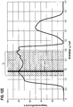
- FIG. 1 shows a diagram of an infrared wavelength spectrum with wavelengths A R on the abscissa and radiation intensities in relative units on the ordinate.
- the infrared wavelength range shown between 0.78 ⁇ m ⁇ ⁇ R ⁇ 5 ⁇ m is usually in a near infrared region, which includes the wavelengths between 0.78 microns ⁇ ⁇ R ⁇ 3 microns, and a far or long wavelength infrared region with wavelengths ⁇ R ⁇ 3 microns divided up.
- the near infrared range between 0.78 ⁇ m ⁇ ⁇ R ⁇ 3 ⁇ m is in turn divided into a short-wave infrared range IR-A and a medium-wave infrared range IR-B.
- the limit forms the absorption line for water or moisture in the air at 1.4 microns, so that the IR-A range between 0.78 microns ⁇ ⁇ R ⁇ 1.4 microns and the IR-B range between 1.4 ⁇ m ⁇ ⁇ R ⁇ 3 ⁇ m.
- Halogensammlungstrahler are usually operated at 2400 - 2600 ° C, wherein the maximum intensity in the short-wave infrared range at a wavelength ⁇ R of about 1.0 microns.
- the intensity maximum I M for different annealing temperatures of a filament shifts from the short-wave IR-A range over the medium-wave IR-B range to the long-wave IR-C, the maximum radiation intensity decreases with increasing infrared wavelength, as is the curve a for the maximum Wavelengths at operating temperatures between 2600 ° C for Halogensammlungstrahler to operating temperatures of 900 ° C for resistance heater shows.
- the maximum values of the heating tube elements of the present invention in which carbon fibers are used, which are braided into a carbon cord and operated at filament operating temperatures T B between 1400 ° C ⁇ T B ⁇ 1800 ° C.
- the maximum values of the radiation intensity in relative units occur at these filament operating temperatures at infrared wavelengths of> 1.2 ⁇ m, so that it is advantageous if, for the infrared radiator with carbon fibers according to the invention, an infrared wavelength range between 1.2 ⁇ m ⁇ ⁇ R ⁇ 2.4 ⁇ m is selected and all components, be it the infrared heating coil or the infrared reflector of the radiant heater, are optimized for this infrared range according to the invention.
- This inventive and optimized infrared range forms a transition region 13 from the IR-A to the IR-B infrared radiation range, so that both the maxima for the filament temperatures of 1400 ° C to 1800 ° C lie advantageously in this inventive infrared transition region 13 of the invention as well the water absorption wavelength 1.4 ⁇ m is included in this infrared junction region 13.
- infrared heaters operate or are optimized exclusively in the medium-wave IR-B range or long-wave IR-C range, excluding the water absorption wavelength 1.4 ⁇ m.
- An optimization in the infrared transition region according to the invention is essentially determined by correspondingly adapted reflection properties of the infrared reflectors used in such radiant heaters.
- this diagram is in FIG. 1 clear that carbon cords or Karbonterrorismspiralen that operate in a temperature range between 1400 ° C and 1800 ° C, an optimal energy balance in the inventive Infrared transition region with the infrared wavelengths between 1.2 microns ⁇ ⁇ R ⁇ 2.4 microns can achieve.
- the problem must be solved to provide a dimensionally stable carbon cord made of a variety of carbon fibers, which can be brought in a quartz tube free from the inner wall of the quartz tube dimensionally stable to annealing temperatures between 1400 ° C and 1800 ° C.
- the problem to be solved is to pass the ends of the KarbonMapspirale through the heating tube, which usually consists of a quartz tube.
- FIG. 2 shows a schematic cross-section through an end portion 14 of an infrared heater tube element 2.
- a molybdenum connecting wire 62 is further fixed, which is connected to a molybdenum strip 16, on which the end portion 14 of the quartz tube is pressed, wherein a through hole 17, which in turn consists of a Molybdäneducationsdraht 62, protruding from the compressed quartz tube end and in an outer plug 61 passes.
- a heating current can now be applied externally to the carbon heating coil 45 via the through-connection 17, the molybdenum strip 16, the molybdenum connecting wire 62 and the metal transition element 15 made of pure nickel.
- the filament operating temperature T B between 1400 ° C ⁇ T B ⁇ 1800 ° C is reached in a few seconds, without an inrush current control with a corresponding current limit for the heating element of the invention of the radiant heater is required.
- the spiral structure of the dimensionally stable Karbonsammlungspirale 45 made of braided carbon fibers 10 results in spacious spaces between the individual turns of Karbonterrorismspirale 45, so that a shading of either arranged on the heating tube 3 infrared reflector or behind the heating tube fixed infrared reflector is correspondingly low.
- An infrared reflector is required to align the infrared radiation from a rear side of the heating tube element 2, for example, to a front side of the radiant heater.
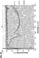
- FIG. 3 shows with the FIGS. 3A and 3B Charts of reflection coefficients R as a function of the infrared wavelength ⁇ R for three different qualities QI, QII and QIII of anodized aluminum sheets as reflectors.
- FIG. 3A shows a diagram for the wavelength range between 0.25 microns ⁇ ⁇ R ⁇ 2.5 microns with the range of visible light sL, the range of short-wave infrared rays IR-A between 0.78 microns ⁇ ⁇ R ⁇ 1.4 microns with the Absorption line for water at 1.4 ⁇ m as a characteristic limit to the medium-wave range IR-B between 1.4 ⁇ m ⁇ ⁇ R ⁇ 3.0 ⁇ m.
- the transition region 13 according to the invention is in FIG. 3A hatched and all three qualities QI, QII and QIII show excellent reflection properties with a reflection coefficient in the entire inventive transition region 13 between 1.2 microns ⁇ ⁇ R ⁇ 2.4 microns of over 90% and for the quality QIII even to 98% in the decisive radiation range for the carbon heating spirals used according to the invention.
- the reflection coefficient drops markedly for the excellent qualities QII and QIII in the IR range of interest. Then, the reflection coefficient R steeply increases and reaches for the infrared wavelength range ⁇ R according to the invention between 1.2 .mu.m.ltoreq. ⁇ R ⁇ 2.4 .mu.m and up to 10 .mu.m maximum values, the up to 98% reflection in the inventive infrared transition region 13 and beyond > 10 ⁇ m as the following FIG. 3B shows deliver.
- the high IR reflection is thus retained even in the long - wave infrared range> 10 ⁇ m and also reflects the lower proportion of the IR - C radiation of the carbon heating elements with predominant absorption in the air.
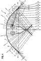
- FIG. 4 shows a schematic cross section through an elongated infrared reflector 5, the two focus areas 25 and 25 ', in which two Schurohrimplantation 2 and 2' in the focal areas 25 and 25 'of the bends 4 and 4' of the infrared reflector 5 can be arranged.
- the infrared rays which strike the curved region of the infrared reflector 5 in the direction of the arrow A are reflected as almost parallel heating rays in the direction A 'on a front side of a radiant heater.
- reflective segment strips 21, 22 and 23 are arranged in an edge region 19 and segment strips 21 ', 22' and 23 'are present in an opposite edge region 20. These reflective segment strips 21, 22 and 23 or 21 ', 22' and 23 'are flat on the entire length of the infrared reflector.
- the reflection angle changes stepwise, for example by 5 °.
- a preferably 1 mm wide bead 24 is disposed in the transition.
- Infrared rays emanating in the direction B from the segment strips 21 'm from the infrared heater tube 2' are reflected in direction B ', the angle of incidence beta being equal to the angle of departure beta'.
- the infrared reflector 5 has bends 65 and 66, which can be used to fix the infrared reflector 5 in its position within a housing of a radiant heater floating.
- infrared energy is emitted, but also on the back 31 of the infrared reflector 5 residual heat as radiation occur because in the infrared transition region despite matched reflection properties about 2% of the radiation are not reflected, but either absorbed in the reflector material or, as shown by the arrows in the direction of arrow C, radiated from the outer surface 31 of the infrared reflector 5 with up to 2%. Since the infrared reflector also absorbs a minimum proportion of the heating radiation, the infrared reflector is heated to 180 ° C maximum during operation, in particular at filament annealing temperatures of 1800 ° C with the result that a surrounding housing is heated.
- FIG. 5A shows three main components, namely as the first main component two Bankrohremia 2 and 2 ', as a second main component an infrared reflector 5 with two focal areas 25 and 25' forming bends 4 and 4 'and as a third main component, a housing 6 with edge side contours 8 and 8' and Back side contours 9 and 9 'and a front side 7, which may be covered by an infrared transparent front glass plate 39 or a protective grid with protective louvers.
- the front glass plate 39 has as FIG. 5B shows in detail, on their edges 106 a circumferential U-shaped ornamental and clamping frame 107.
- the ornamental and clamping frame 107 not only encloses the edges 106 of the front glass plate 39, but connects the front glass plate 39 with S-shaped brackets 73, which protrude with one end in longitudinal slots 42 of silicone profile pieces 67.
- a second end of the bracket 73 is encompassed by the ornamental and clamping frame 107 and clamped to the edges 106 of the front glass plate 39.
- the silicone profile pieces 67 are arranged positively in a guide groove 68 by the contour of the silicone profile pieces 67 are adapted to bulges of a contour of the guide groove 68 or to a trapezoidal shape of the cross section of the guide groove 68.
- the heating tube elements 2 and 2 ' have the in FIG. 2 shown infrared heating coils made of a carbon cord.
- the heating tube elements 2 and 2' are arranged in the above-mentioned focus areas 25 and 25 'of the curvatures 4 and 4' of the infrared reflector 5 , On the effect of the segment strips 21, 21 ', 22, 22', 23 and 23 'in the edge regions 19 and 20 was already in the description of the FIG. 4 received.
- the housing 6 from the front side 7 with the front glass plate 39 and the edge sides 8 and 8 'and the rear side structures 9 and 9' surrounds the infrared reflector 5 and the two heating tube elements 2 and 2 '.
- an air convection channel 27 is formed, which extends from the curved outer surface 31 of the infrared reflector 5 to a highly structured inner side of the edge structures 8 and 8 'and the rear side structures 9 and 9'.
- the air convection 27 protrude bulges 33 of different characteristics, causing air turbulence in the Lucaskonvemiemieal 27, whereby the cooling of both the back 31 of the infrared reflector 5 and the rear side structure 9 of the housing 6 is intensified.
- the infrared reflector 5 is not rigidly fixed in the housing 6, but the bends 65 and 66 in the edge regions 19 and 20 of the infrared reflector 5 are held by the rubber-elastic silicone profile pieces 67 and 67 'in the guide grooves 68 floating, the silicone rubber profile pieces 67 and 67 'are arranged only in pieces or at points along the length of the guide grooves 68. Between the silicone profile pieces 67 and 67 'are slotted or slot-shaped openings 28 and 29 are provided, via which an air exchange between the air convection 27 and the environment in the direction of arrow A takes place.
- the housing 6 has a central opening 30 in an upper region, over which in a suitable position of the radiant heater 1 it FIG. 5A shows the heated air of the Lucaskonvekomskanals 27 can escape.
- the opening 30 between two half-shells 34 and 35 is provided with a perforated metal sheet strip 38, through which the heated air can escape or at a changed position of the radiant heater 1 as it FIG. 5C shows in the air convection 27 can penetrate. Whether air flows into the air convection channel 27 via one of the openings 28, 29 or 30 or flows out alone the geodetic height difference between the openings 28, 29 and 30 is crucial.
- FIG. 5C is the front glass plate 39 of the radiant heater 1 with respect to the horizontal position of FIG. 5A at an angle of inclination ⁇ , for example, arranged on a wall, so that the opening 28 has the lowest geodetic height and the incoming air through the opening 28 on two Heilkonvemiemieskanäle 27 and 27 'in the direction of arrow A or arrow B distributed.
- the air convection channel 27 ' is formed between the front glass plate 39 and the infrared reflector 5 and reduces the thermal load on the front glass plate 39, which is designed for temperatures ⁇ 1200 ° C, while in the air convection 27 'arranged adjacent to the front glass plate 39 Karbonterrorismspiralen 45 and 45' in the Schurohr electroden 2 and 2 'are designed for annealing temperatures up to 1800 ° C.
- the two housing halves 34 and 35 are preferably made of extruded aluminum profiles and on the one hand by not shown end covers and on the other hand by at least two connecting pieces 36, as in the FIGS. 5A and 5C be shown, positively held together. These connecting pieces 36 are arranged at least at both end regions of the elongated housing 6. These connecting pieces 36 have bulges 69 and 69 ', which engage with guide rails 70 and 70' of the structured inner walls of the housing half-shells 34 and 35, respectively.
- edge regions 8 and 8 'in the FIGS. 5A, 5B and 5C outer joining grooves 105 and 105 ' which are provided for insertion, for example, in a suspended ceiling construction or for joining a plurality of radiant heaters 1 to a radiant heater surface.
- the outer joint grooves 105 and 105 ' extend over the full length of the radiant heater. 1
- FIG. 6 shows with the Figures 6A, 6B and 6C schematic cross sections through a radiant heater 1 'according to a second embodiment of the invention.
- Components having the same functions as in the previous figures are identified by the same reference numerals and will not be discussed separately.
- the front grid structure 44 has a molded and stamped complete front shield made of stainless steel or an aluminum alloy and has Ablelamellen 74 and 74 'as a secure shielding of the Schurohremia 2 and 2' against access.
- the holder angle 73 and 73 'of the front grid structure 44 together with the folds 65 and 66 of the infrared reflector 5 in the longitudinal slots 42 and 42nd 'of the silicone profile pieces 67 and 67' floatingly mounted relative to the housing 6.
- the front grid structure 44 is designed such that about 75% of the front side 7 of the housing 6 is open and unhindered the infrared radiation of the infrared heater tubes 2 and 2 'are directed with the reflected portion of the infrared reflector 5 to be heated areas of the environment.
- the silicone profile pieces 67 and 67 ' which ensure the floating support of the infrared reflector 5 and the front grid structure 44, leave a sufficient surface of the elongated openings 28 and 29 free, so that in the air convection 27 in all mounting positions of the radiant heater 1' an outer surface 31st of the infrared reflector 5 can form cooling air convention.
- the material of the infrared reflector 5, which consists of an anodized aluminum alloy, has a low absorption coefficient, yet the infrared reflector can be heated up to 180 ° C and due to the cooling air convection in the air convection 27, the back of the housing 6 reaches at most one temperature between 60 ° C and 100 ° C with a heating capacity of the heating tube elements of up to 3.2 kW.
- the air convection channel in FIG. 6a the same conditions already apply FIG. 5A were discussed. The same applies to the formation of Lucaskonvetechnischmieskanäle 27 and 27 'of FIG. 6C however, in FIG. 6C Through all openings of the front grid structure 44 air in the air convection 27 'reach, if in contrast to FIG. 5C no front glass pane is provided.
- FIG. 7 shows in FIG. 7A a schematic cross section through the radiant heater according to FIG. 6 along a section line AA, which in FIG. 7B will be shown.
- This cutting plane is exactly laid by a Ablelamelle 74, so that in FIG. 7A the contour of such Ablelamelle 74 of the front grid structure 44 shown in cross section becomes.
- Radiant heaters up to 3200 watts can be realized with such a front grid structure 44, without the infrared reflector does not change in its geometry during the entire life of more than 10,000 hours of operation. This is supported by the above-mentioned beads 24 and 24 'in the lower edge regions 19 and 20 of the infrared reflector 5.
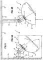
- FIG. 8 shows with the Figures 8A and 8B schematic views of a radiant heater 1 in wall mounting and ceiling mounting.
- guide rails 50 and 51 are arranged in the housing rear side structure 9 and 9 'of the half shells 34 and 35, in which holding elements 76 and 77 of a holding arm 52 can slidably slide to adjust the holding arm 52 in an optimum position along the guide rails 50 and 51 can.
- the support arm 52 is adjustably fixed via a joint 78 with a wall stand 79 fixable on a wall stand 80, wherein the wall stand 80 is composed of a support rod 81 and a tripod 82, so that an arbitrary setting angle ⁇ of the front side 7 of the radiant heater 1 is adjustable.
- the wall stand 80 is composed of a support rod 81 and a tripod 82, so that an arbitrary setting angle ⁇ of the front side 7 of the radiant heater 1 is adjustable.
- ceiling mounting the same support arm 52 can be used with the joint 78 and the stand rod 81, wherein the stand 82 is now fixed to a ceiling 84 and to set an optimal radiation distance a from the area to be heated extension rods 83 between the tripod 82 and the stand rod 81 can be arranged.
- Such extension rods 83 may also be used to fit in Figure 8A to vary a distance a 'from the wall 79.
- it is possible with simple standardized components such as a tripod 82, a support rod 81, a pivot
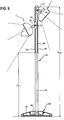
- FIG. 9 shows a schematic view of radiant heaters 1, which are arranged on a stand 64 vertically displaceable and pivotally.
- the stand 64 has a stand base 108, which is adapted to the outer dimensions of the heat radiator 1 which is displaceably and pivotably mounted on the stand 64.
- the stand base on a stand foot plate 85 which is a stabilizing counterweight to the weights of the radiant heaters! forms.
- the stand 64 is essentially a profile tube in which feeder cables 86 are arranged from the stand base 108 to the radiant heaters 1.
- a height a min from the pedestal base 108 to a lower edge of two guide rails 88 and 89 for the two radiant heaters 1 may be provided.
- Bankstrahlerhalterept 87 hinges 78, to each of which a support arm 52 as he already from the FIG. 8 is known for the radiant heater 1 is arranged.
- the guide rails 88 and 89 extend up to a maximum distance a max of, for example, a max ⁇ 3.0 m, while the minimum distance a min between the stator base 108 and the radiant heater 1, for example, a minimum distance a min ⁇ 1.80 m. This ensures that infants do not reach the radiant heater 1 of the stator 64.
- Such an arrangement of radiant heaters 1 on a stand 64 with a suitable stable pedestal base 108 has the advantage that when stationary mounting the radiant heater 1 in a large area, for example, between 1.80 m and 2.50 m in their distance from the stator base 108 adjusted can be.
- the inclination angle ⁇ due to the hinge 78 can be adjusted.
- the radiant heater 1 can be operated both horizontally and vertically because the safety height for infants is maintained in any case and the vertical adjustability between a minimum distance a min and a maximum distance a max is limited.
- FIG. 10 shows a schematic view of a Bankstrahlerpilzes 32, which is arranged on a stand 64, wherein the stand 64 can telescopically arrange the Bankstrahlerpilz 32 at different heights.
- a controller 46 may be arranged with a power level switch 47 and a temperature controller 48.
- the radiator mushroom 32 differs from the previous radiant heaters by annular heating tube elements 2 and 2 ', which are arranged in focus areas 25 and 25' of an infrared reflector 5 ', which has the curvatures 4 and 4'.
- the annular infrared reflector 5 is in this case corresponding to the Bankrohrmaschinen 2 and 2 'also annular.
- a front face 7 of the annular radiant heater 1 "has an angle of inclination ⁇ which allows the radiant heater 32 to radiate an increased radius in the environment with infrared rays, and the boundaries of the radiance due to the annular infrared reflector 5 'are indicated by dashed lines 90 and 91 By changing the angle ⁇ these limits can be shifted.
- An air convection channel 27 can again form between the mushroom-shaped rear side 9 and the outer surface 31 of the annular infrared reflector 5 ', wherein the air flows into the air convection channel 27 through an annular opening 28 and over a corresponding annular opening 30 in the mushroom tip of the radiant heater mushroom 32 flows out.
- FIG. 11 a schematic cross section through the Schustrahlerpilz 32 according to FIG. 10 in detail shows.
- the convection in the air convection 27 is not limited to the distance between an outer surface 31 of the annular infrared reflector 5 'and an inner surface 18 of the mushroom-shaped housing 6, but, as the arrow C show, there is also an air convection between the infrared reflector 5' and the annular front glass plate 39 '.
- Both the annular infrared reflector 5 'and the annular front glass plate 39' are supported, held and fixed by a central holding element 92, which projects into the heat radiator mushroom 32.
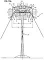
- FIG. 12 shows with the FIGS. 12A and 12B a radiant heater according to FIG. 11 as a parking heater and ceiling heater and with the Figures 12C . 12D and 12E Transparency curves for different glass qualities of a front glass plate 39.
- a special colored glass plate is used as an annular front glass plate 39 when operating the Schustrahlerpilzes 32 in the direction of arrow B, which is colored on the one hand with color pigments which colored the visible spectral component of KarbonMapspiralen at, for example, a filament temperature of 1800 ° C.
- FIG. 12C The course of the transparency coefficient of a first front glass panel quality for transparent front glass panels shows FIG. 12C with nearly 90% both in the visible light range and in the infrared transition region 13 according to the invention, including the absorption line for moisture or water molecules of 14 micrometers. After the transition region 13 according to the invention, the infrared transparency drops steeply.
- the transparency in the visible light range is for white or milky appearing front glass panels of a second quality as it FIG. 12D shows significantly reduced, while in the transition region 13 according to the invention, the transparency partially exceeds 80% and falls steeply after the transition region 13 again.
- the construction of a floor lamp 111 with Bankstrahlerpilz 32 corresponds to the construction according to FIG. 10 ,
- the ambient air flows through the annular slot 28 in the direction of arrow A and divides in two directions E and F, the air in the direction of arrow E through the air convection 27 between the Rear side 31 of the infrared reflector 5 'is passed.
- the air in the direction of arrow F cools both the colored or white front glass pane 39 and the inner surface of the infrared reflector 5 'and can pass from the air convection duct 27' to the air convection duct 27 via a pinhole 114 or a ring slot in the infrared reflector 5 '. Finally, the heated cooling air escapes into the environment in the direction of arrow C via the common central opening 30.
- FIG. 12B shows the same radiator mushroom 32 now as a ceiling light 112 and at the same time as a radiant heater 1 ", which immerses a room in a warm light atmosphere with simultaneous heat generation
- FIG. 12A is shown, replaced by a ceiling mounting rod 113 and with the FIG. 8 fixed stand 82 fixed to a ceiling 84.
- FIG. 13 shows with the FIGS. 13A and 13B a Bankstrahlerpilz 32 with an enveloping structure 100 in the form of a lampshade 109.
- the Schustrahlerpilz 32 has been put on a decorative lampshade 109, which lights up in the direction of arrow G when a fluorescent tube 110 or a LED light ring or other lighting means is operated in the visible spectrum of the light ,
- the brightness of the standardized annular fluorescent tube 110 or of the illumination means can be dimmed steplessly, independently of the power for the heat radiator mushroom 32.
- the diameter D L of the lampshade 109 is slightly larger than the diameter D F of the annular front side 7 of the radiant heater mushroom 32, so that the enveloping structure 100 can be placed in the form of the lampshade 109 on the Schwarzstrahlerpilz 32 before the Schustrahlerpilz 32 on the top 94 of Stand 64 is placed.
- the Edelstrahlerpilz 32 itself may be additionally provided with a colored appearing annular front glass 39 and radiate independent of the fluorescent tube 110 or from the LED light ring or from the other lighting means colored light under the Edelstrahlerpilz 32 in the direction of arrow B.
- Ambient air may be supplied for cooling the lampshade 109 and the infra red reflector via coaxially arranged annular slots 28 and 29 and distributed to three air convection channels 27, 27 'and 27 " FIG. 12 and communicate with the annular opening 28.
- the air convection channel 27 " is disposed between the housing 6 'of the heater core 32 and the lampshade 109 and communicates with the annular slot 29.
- the heated cooling air from the three air convection channels 27, 27' and 27" finally escapes via a central one in the lampshade 109 arranged opening 30th
- FIG. 13B shows the same Schwarzstrahlerpilz 32 now as a ceiling light 112 with a lampshade 109 as the enveloping structure 100 of Schustrahlerpilzes 32.
- the space are immersed in a warm light atmosphere with simultaneous heat generation and, in addition, under the lampshade, for example, the fluorescent tube or LED illuminated rim 110 is arranged as a lighting means.
- the in FIG. 13A is shown replaced by a ceiling mounting rod 113 and with the FIG. 8 fixed stand 82 fixed to a ceiling 84.
- the function of the lampshade 109 is not affected by the suspension on a ceiling 84.
- the enveloping structure 100 can take on different shapes, be it a trapezoidal shape, as in this embodiment as a lampshade 109, or a funnel shape or a cylindrical shape or otherwise a slender outer contour which, for example, resembles a flower blossom.
- the power control and temperature control of the infrared radiator may be located away from the enveloping structure 100 in a portable controller operatively connected to a control module in the radiant heater 32, in addition to a brightness control for the fluorescent tube 110 or for a LED light ring or for another Lighting means may be integrated into the portable control device.
- FIG. 14 shows with the Figures 14A and 14B schematic cross sections through an infrared heater tube element 2.
- the infrared heater tube element 2 radiates from a Karbonsammlungspirale 45 with approximately constant radiation intensity in all directions, as shown by the radiation arrows A.
- the Karbonterrorismspirale 45 consists of braided carbon fibers 10, which are braided into a carbon cord and wound into a dimensionally stable Karbonterrorismspirale 45 by a special process and dimensionally stabilized.
- the Karbonterrorismspirale 45 is, as shown in Fig. 14A, applied in an evacuated or filled with inert gas heating tube 3 made of quartz glass with electricity, as it already with the FIG. 2 has been explained, and operated in the temperature range of the invention between 1400 ° C and 1800 ° C, wherein radiation intensity maxima in a transition region according to the invention the infrared wavelengths ⁇ R between 1.2 microns ⁇ ⁇ R ⁇ 2.4 microns occur.
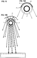
- Figure 14B shows an infrared reflector 5 is used, which ensures that due to a high to 98 percent reflection coefficient of the infrared reflector 5, almost all the infrared radiation energy in the in Figure 14B reflected radiation directions is reflected.
- the infrared rays reach the transition region according to the invention, such as Figure 14B shows a low penetration depth for surfaces 119 of various materials, as indicated by the dotted line 95 in FIG Figure 14B shows.
- water molecules absorb the infrared radiation of 1.4 ⁇ m at a normal atmospheric humidity, so that the infrared radiation of a carbon radiator rapidly heats up moisture or water molecules in this wavelength range, which provides a pleasantly warming environment.
- FIG. 15 shows with the FIGS. 15A and 15B schematic cross-sections through an infrared heater tube 2 ', which differs from the Schurohrelement 2, which in FIG. 14 is distinguished, characterized in that directly on the quartz tube 3, a reflector material is applied, which consists of an oxide ceramic layer 96 and has an infrared wavelength-dependent reflection coefficient, as shown in the illustration of FIG. 3 is shown, wherein the reflection coefficient is tuned to the infrared wavelength range according to the invention between 1.2 microns ⁇ ⁇ R ⁇ 2.4 microns and up to 10 microns.
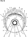
- FIG. 16 shows a schematic cross section through a compact radiant heater 1 "according to a further embodiment of the invention .
- the housing 6 of this radiant heater 1" is adapted in shape to a protective tube 98 and can be pushed onto the protective tube 98.
- the infrared heater tube on the structure, which in Figure 15A will be shown.
- FIG. 15B shown heat shield 97 is in Figure 16B applied to an inner wall of the housing 6 adapted to the protective tube 98.
- the protective tube 98 is preferably made of a quartz tube, the surface 119 of which is frosted, so that the infrared-transparent properties for the infrared radiation range are maintained and diffusion of the light radiation occurs only in the visible wavelength range.
- the glowing Karbonterrorismspirale 45 they do not stand out from the outside on the outer protective tube 98 made of quartz glass with a frosted surface 119 from.
- the heat shield 97 between the protective tube 98 made of quartz glass and the aluminum housing profile with appropriate ventilation through the air convection channel 27 provided protects the material of the housing 6, which is located behind the heat shield 97, from overheating.
- a further channel 99 can be provided behind the heat shield 97 to allow internal electrical wiring of the radiant heater 1 "and to protect the electrical wiring from overheating.
- FIG. 17 shows a schematic diagram with remotely controlled power setting and temperature control of a radiant heater 1, here for example on an outer or an inner wall 79 with the FIG. 9 shown holding arm 52 is fixed.
- This radiant heater 1 is set in this embodiment of the invention via a portable control unit 46, which is arranged here for example on a table, both in power levels and by temperature control.
- a radio link 101 between the portable control unit 46 and a control module 63 in the radiant heater 1.
- the portable control unit 46 which is arranged here on a table 102, a temperature sensor 49 which detects the ambient temperature.
- FIG. 18 shows a schematic diagram of a switch unit in FIG. 18A the portable control unit 46 for a radiant heater 1 with an on / off or timer switch 47, a power level switch and program switch 47 ', and + or - push button 47 "for a temperature or timer setting.
- This switch unit is connected to a control and regulation module 63 the front 7 of the radiant heater 1 in radio communication 101, as it FIG. 18B shows.
- the control and regulation module 63 has, in this embodiment of the invention, a display panel on the front side 7 of the radiant heater 1, which centrally signals the set temperature and in addition to the temperature display 129 preferably has three LED lights 130.
- the LED lights 130 may signal a power-on state of the heater 1, a power control, and a power-on state of a timer.
- three more LED displays 130 are provided to signal 3 power levels.
- a temperature controller which is integrated into the control and regulation module 63, is in radio communication with a temperature sensor unit 49.
- the temperature sensor unit 49 comprises in a housing a room temperature sensor 48 and a radiation sensor 48 'exposed on the surface of the housing for irradiation by the radiant heater 1.
- a radio electronics 131 is arranged, which cooperates with the control and regulation module 63 via a radio link 101 '.
- FIG. 19 shows a schematic cross section through a further embodiment of the radiant heater as a dark radiator 59.
- the dark radiator 59 has in this embodiment of the invention three juxtaposed elongated heating tubes 3, 3 'and 3 ", each in a focus region 25, 25' and 25" of Curves 4, 4 'and 4 "of a common heat shield 97 are arranged.
- an air convection 27 is arranged, which in turn forms an air convection in the direction of arrow A through openings 28 and 29 in the form of long slots, wherein the air via an upper opening 30 from the back of the 9th of the housing 6 can escape and thus heats the surrounding room air.
- silicone profile pieces 67 and 67 ' are arranged in guide groove 68 and 68' in the structured edge sides 8 and 8 'of the housing 6.
- the silicone profile pieces 67 and 67 ' have two longitudinal slots 42 and 43 lying one above the other, with folds in the longitudinal slots 42 and 42' 65 and 66 of the heat shield 97 are floatingly mounted, while in the second elongated longitudinal slots 43 and 43 'of the silicone profile pieces 67 and 67' angle pieces 73 and 73 'of a structured front cover 40, which covers the entire front side 7 of the dark radiator 59 are arranged ,
- This front cover 40 is made of an extruded aluminum alloy profile and has bulges 33 on the inner wall 117 of the front cover 40, which highly effectively absorb the infrared rays in the infrared wavelength range according to the invention between 1.2 .mu.m.ltoreq. ⁇ R .ltoreq.2.4 .mu.m and for conversion into Heat rays provide, so that the front cover 40 radiates to a preferred heat radiation in the long-wave infrared range IR-C between 250 ° C and 500 ° C, preferably between 300 ° C and 400 ° C.
- the outer contour of the front cover 40 has equidistantly arranged radiation ribs 118, which provide for an intensive contact with the ambient air and the ambient humidity.
- the heating tube elements 3, 3 'and 3 "have in addition to the heat shield 97 a directly applied to the quartz tubes infrared reflectors 5" from a reflector coating of oxide ceramic.
- the new heating profile with effective heat absorption of the long-wave infrared range and delivery to the surrounding room air is followed by a subsequent FIG. 21 explained in more detail.
- FIG. 20 shows with the Figures 20A and 20B schematic cross-sections through an infrared radiator 53 according to another embodiment of the invention.
- the infrared radiator 53 is a stand-alone device that can be placed in a room to be heated, especially when the room air is to be heated as quickly and quickly.
- the infrared radiator 53 has a housing 6 in which a plurality of air convection passages 27, 27 'and 27 "are provided
- a first air convection passage 27 receives the cool and moist room air flowing in the direction of the arrow A in the floor area and directs it in the direction of the arrows B and C directly to the Heating tube emitters 2 of quartz tubes with inner Karbonikispiralen over, so that this air and moisture molecules are exposed to the infrared radiation range according to the invention by, as already mentioned several times, the absorption line with 1.4 microns of the infrared wavelength spectrum is included, so that the humidity relatively quickly and quickly generates hot water molecules, which mix with the room air and flow out of respective openings 29 at the upper end of the infrared radiator.
- infrared radiators 2 with a quartz tube are used in this radiator, which has an immediately applied infrared reflector 5 "made of anodized aluminum on its rear side, so that the radiated heat is strongly attenuated on the rear side of the infrared heating tubes 3. Nevertheless, a back ventilation flow in the air convection duct 27 in the direction of arrow C and also absorbs heat, which is discharged through the air flow C through an upper opening 29 to the room air.
- a further air convection duct 27 " which allows the cooler ground air to flow into the air convection duct 27" via the bottom opening 28, this air convection duct 27 “being separated from the infrared radiator pipe 3 by an intermediate wall 55.
- the structure of the partition 55 will be described hereinafter FIG. 21 shown in cross section.
- the heating of the room air is delayed, but then heated with greater efficiency as soon as the intermediate wall 55 has reached an operating temperature between 200 ° C and 800 ° C, preferably between 350 ° C and 600 ° C.
- the front 7 is heated only to the permissible for infrared radiators temperature ranges, which are far below the temperatures of the intermediate wall 55.
- Figure 20B shows a section of two parallel heating tube elements 2, which have on their backs a corresponding reflector coating and additionally spaced together from a heat shield 97 in the form of another heat reflector and are partially enveloped.
- FIG. 21 shows a schematic cross section through an intermediate segment 121 of a partition wall 55 in the infrared radiator 53 according to FIG. 20 .
- a structure of a partition wall 55 can also be used for the in FIG. 19 shown dark radiator 59 are used as a front cover 40.
- heating tubes 3 with partially frosted surfaces are used, which have an oxide ceramic reflector 5 "on the outside of the quartz tube of the heating tube element 2.
- an anodized aluminum plate is used as a heat shield 97 behind the carbon heating tube elements 2 for reflection of residual heat radiation still acting to the rear Protection against heating of the rear of the case 9.
- the intermediate wall 55 can be plugged together from a plurality of intermediate wall segments 121.
- the intermediate wall segments 121 are extruded aluminum profiles.
- the aluminum profiles have a plurality of heat absorption ribs 120 facing the infrared heater tube element 2, which are aligned at a distance from one another and onto one of the heating tube elements 2.
- the heat-absorbing ribs 120 are fixed to aluminum arches, which form a kind of hollow radiator and the radiant energy converted into the long-wave infrared to the third Lucaskonvemiemiemieal 27 "in the direction of arrow B.
- the heat absorption ribs 120 on the back of the intermediate wall 55 and the curved infrared beam profiles in the form of aluminum sheets 122 on the front of the intermediate wall 55 can be done by a thin-walled intermediate wall rapid heating of the same and with little delay, the air convection 27 "between the intermediate wall 55 and the front wall of the infrared radiator, not shown, provide for a rapid permanent heating of the environment.
- FIG. 22 shows with the Figures 22A and 22B 3 shows schematic views of a heater blower 60 with an infrared heater element 1 "of annularly curved infrared heater tube elements 2", in which case two of the heating tube elements 2 "are arranged coaxially in one another and consist of quartz tubes with a reflector coating as already described above Heat quartz tube applied and consists essentially of aluminum dioxide as anodized coating 2 "is arranged so that it is positioned coaxially to the axis 123 of an axial fan 124 and the air blower, as it Figure 22B shows, can flow directly past the infrared carbon heating 2 ".
- the heating fan 60 Due to the absorption capacity at the infrared wavelength 1.4 ⁇ m for moisture in the air, the passing air enriched with air moisture rapidly heats up and gives a pleasant room climate, whereby the heating fan 60 is protected by corresponding shutters 126 both in the inlet area 125 and in the outlet area 127 is, so that the radial fan 60 can work without interference.
- Corresponding switching elements 128 can be arranged directly on the heating fan 60, which, on the one hand, gradually switch the power and, on the other hand, use a room thermostat with a temperature controller to set and regulate the temperature gradually or steplessly.
- a radial fan is provided in a further embodiment not shown de invention, which cooperates with at least one elongated Karbonikispirale in at least one straight heating tube element.
- a grid of Schuntzmien cooperates with such a radial fan.
Landscapes
- Engineering & Computer Science (AREA)
- Chemical & Material Sciences (AREA)
- Combustion & Propulsion (AREA)
- Mechanical Engineering (AREA)
- General Engineering & Computer Science (AREA)
- Physics & Mathematics (AREA)
- Thermal Sciences (AREA)
- Ceramic Engineering (AREA)
- Resistance Heating (AREA)
- Electric Stoves And Ranges (AREA)
Description
- Die Erfindung betrifft einen Heizstrahler mit Heizrohrelement. Das Heizrohrelement weist ein Heizrohr auf, das für Infrarotstrahlen transparent oder semitransparent ist. Das Heizrohr ist in einem Fokusbereich eines mindestens eine fokussierende Krümmung aufweisenden Reflektors angeordnet. Das mindestens eine Heizrohrelement ist in einem Gehäuse mit mindestens einer für Infrarotstrahlen offenen oder transparenten oder semitransparenten Frontseite angeordnet.
- Ein derartiger Heizstrahler ist aus der Druckschrift
DE 39 03 540 A1 bekannt. Dabei dient der Reflektor der Ausrichtung der Wärmestrahlung zu einer offenen Frontseite des Gehäuses hin. - Die in den bekannten Heizstrahler eingesetzten Heizröhren sind in der obigen Druckschrift nicht näher beschrieben und können als Infrarotstrahler ein Heizelement aus Karbonfasern aufweisen, wie es aus der Druckschrift
EP 1 168 418 B1 bekannt ist. Das bekannte Heizelement aus Karbonfasern ist in einem Quarzrohr angeordnet, wobei die Karbonfasern die Form einer Wendel eines Karbonbandes aufweisen. Eine derartige Wendel eines Karbonbandes aus Karbonfasern hat den Nachteil, dass es den Reflektor breitbandig abschattet, so dass der abgeschattete Bereich des Reflektors nicht zur Reflektion der Infrarotstrahlen in Richtung auf die offene oder infrarottransparente oder infrarotsemitransparente Frontseite des Heizstrahlers beitragen kann. - Das Dokument
EP2249617 offenbart einen Heizstrahler gemäß dem Oberbegriff des Anspruchs 1. - Aufgabe der Erfindung ist es, einen verbesserten Heizstrahler zu schaffen, der die Infrarotstrahlung von Karbonfasern besser nutzt.
- Diese Aufgabe wird mit dem Gegenstand des unabhängigen Anspruchs 1 gelöst.
- Die Erfindung wird nun anhand der beigefügten Figuren näher erläutert.
- Figur 1
- zeigt ein Diagramm eines Infrarotwellenlängenspektrums;
- Figur 2
- zeigt einen schematischen Querschnitt durch einen Endbereich eines Infrarotheizrohrelements;
- Figur 3
- zeigt mit den
Figuren 3A und3B Diagramme von Reflexionskoeffizienten in Abhängigkeit von der Infrarotwellenlänge für drei verschiedene Qualitäten QI bis QIII von eloxierten Aluminiumblechen; - Figur 4
- zeigt einen schematischen Querschnitt durch einen langgestreckten Infrarotreflektor;
- Figur 5
- zeigt mit den
Figuren 5A, 5B und 5C einen schematische Querschnitte durch einen Heizstrahler gemäß einer ersten Ausführungsform der Erfindung; - Figur 6
- zeigt mit den
Figuren 6A, 6B und 6C schematische Querschnitte durch einen Heizstrahler gemäß einer zweiten Ausführungsform der Erfindung; - Figur 7
- zeigt in
Figur 7A einen schematischen Querschnitt durch den Heizstrahler gemäßFigur 6 entlang einer Schnittlinie A-A, die inFigur 7B gezeigt wird; - Figur 8
- zeigt mit den
Figuren 8A und 8B schematische Ansichten eines Heizstrahlers in Wandmontage und in Deckenmontage; - Figur 9
- zeigt eine schematische Ansicht von Heizstrahlern an einem höheverstellbaren Stativ;
- Figur 10
- zeigt eine schematische Ansicht eines Heizstrahlers in Pilzform;
- Figur 11
- zeigt einen schematischen Querschnitt durch den Heizstrahlerpilz gemäß
Figur 10 im Detail; - Figur 12
- zeigt mit den
Figuren 12A und12B einen Heizstrahler gemäßFigur 11 als Standheizstrahler und als Deckenheizstrahler und mit denFiguren 12C ,12D und12G Transparenzkurven für unterschiedliche Glasqualitäten einer Frontglasplatte; - Figur 13
- zeigt mit den
Figuren 13A und13B einen Heizstrahler mit einer Hüllstruktur in Form eines Lampenschirms, in Kombination Standheizstrahler / Stehlampe und Deckenheizstrahler / Deckenlampe - Figur 14
- zeigt mit den
Figuren 14A und 14B schematische Querschnitte durch ein Infrarotheizrohrelement; - Figur 15
- zeigt mit den
Figuren 15A und 15B schematische Querschnitte durch ein Infrarotheizrohrelement mit aufgebrachtem Infrarotreflektor; - Figur 16
- zeigt einen schematischen Querschnitt durch einen kompakten Heizstrahler gemäß einer weiteren Ausführungsform der Erfindung;
- Figur 17
- zeigt eine Prinzipskizze mit ferngesteuerter Leistungseinstellung und Temperaturregelung eines Heizstrahlers mittels eines tragbaren Steuergeräts;
- Figur 18
- zeigt ein Zusammenwirken von einem in einen Heizstrahler integrierten Steuer- und Temperaturregelmodul mit frei positionierbarer Temperatursensoreinheit und einem tragbaren Steuergerät;
- Figur 19
- zeigt einen schematischen Querschnitt durch eine weitere Ausführungsform des Heizstrahlers als Dunkelstrahler;
- Figur 20
- zeigt mit den
Figuren 20A und 20B schematische Querschnitte durch einen Infrarotradiator gemäß einer weiteren Ausführungsform der Erfindung; - Figur 21
- zeigt einen schematischen Querschnitt einer Zwischenwand in dem Infrarotradiator gemäß
Figur 20 ; - Figur 22
- zeigt mit den
Figuren 22A und 22B schematische Ansichten eines Heizgebläses mit einem Infrarotheizstrahler gemäß einer weiteren Ausführungsform der Erfindung. -
Figur 1 zeigt ein Diagramm eines Infrarotwellenlängenspektrums mit Wellenlängen AR auf der Abszisse und Strahlungsintensitäten in relativen Einheiten auf der Ordinate. Der gezeigte Infrarotwellenlängenbereich zwischen 0,78 µm ≤ λR ≤ 5 µm wird üblicherweise in einen nahen Infrarotbereich, der die Wellenlängen zwischen 0,78 µm ≤ λR ≤ 3 µm umfasst, und einen fernen oder langwelligen Infrarotbereich mit Wellenlängen λR ≥ 3 µm aufgeteilt. Der nahe Infrarotbereich zwischen 0,78 µm ≤ λR ≤ 3 µm wird wiederum in einen kurzwelligen Infrarotbereich IR-A und einen mittelwelligen Infrarotbereich IR-B geteilt. Dabei bildet die Grenze die Absorptionslinie für Wasser bzw. Feuchtigkeit in der Luft bei 1,4 µm, so dass der IR-A Bereich zwischen 0,78 µm ≤ λR ≤ 1,4 µm und der IR-B Bereich zwischen 1,4 µm ≤ λR ≤ 3 µm liegt. - Halogenheizstrahler werden üblicherweise bei 2400 - 2600 °C betrieben, wobei das Intensitätsmaximum im kurzwelligen Infrarotbereich bei einer Wellenlänge λR von etwa 1,0 µm liegt. Das Intensitätsmaximum IM für unterschiedliche Glühtemperaturen eines Glühfadens verschiebt sich von dem kurzwelligen IR-A Bereich über den mittelwelligen IR-B Bereich bis in den langwelligen IR-C, wobei die maximale Strahlungsintensität mit zunehmender Infrarotwellenlänge abnimmt, wie es die Kurve a für die maximalen Wellenlängen bei Betriebstemperaturen zwischen 2600 °C für Halogenheizstrahler bis Betriebstemperaturen von 900 °C für Widerstandsheizstrahler zeigt. Dazwischen liegen die Maximalwerte der Heizrohrelemente der vorliegenden Erfindung, in denen Karbonfasern eingesetzt werden, die zu einer Karbonschnur geflochten sind und bei Glühfadenbetriebstemperaturen TB zwischen 1400 °C ≤ TB ≤ 1800 °C betrieben werden.
- Die Maximalwerte der Strahlungsintensität in relativen Einheiten treten bei diesen Glühfadenbetriebstemperaturen bei Infrarotwellenlängen von > 1,2 µm auf, so dass es von Vorteil ist, wenn für die erfindungsgemäßen Infrarotheizstrahler mit Karbonfasern ein Infrarotwellenlängenbereich zwischen 1,2 µm ≤ λR ≤ 2,4 µm gewählt wird und sämtliche Komponenten, sei es die Infrarotheizspirale oder der Infrarotreflektor des Heizstrahlers, für diesen erfindungsgemäßen Infrarotbereich optimiert werden.
- Dieser erfindungsgemäße und optimierte Infrarotbereich bildet einen Übergangsbereich 13 von dem IR-A zu dem IR-B Infrarotstrahlungsbereich, so dass sowohl die Maxima für die Glühfadentemperaturen von 1400 °C bis 1800 °C in vorteilhafter Weise in diesem erfindungsgemäßen Infrarotübergangsbereich 13 der Erfindung liegen als auch die Wasserabsorptionswellenlänge 1,4 µm in diesen Infrarotübergangsbereich 13 eingeschlossen ist. Das bedeutet nämlich, dass feuchte Luft, die sowohl in Außen- als auch im Innenbereichen vorherrscht mithilfe derartiger Heizstrahler besonders schnell die Strahlungsenergie aufnimmt und eine angenehme aufgewärmte Luftatmosphäre bei der in Mitteleuropa üblichen Luftfeuchte erzeugt.
- Dieser vorteilhafte Effekt wird nicht erreicht, wenn die Infrarotheizstrahler ausschließlich im mittelwelligen IR-B Bereich oder langwelligen IR-C Bereich, unter Ausschluss der Wasserabsorptionswellenlänge 1,4 µm arbeiten bzw. optimiert sind. Eine Optimierung im erfindungsgemäßen Infrarotübergangsbereich wird im Wesentlichen durch entsprechend angepasste Reflexionseigenschaften der Infrarotreflektoren, die in derartigen Heizstrahlern eingesetzt werden, mitbestimmt.
- Zunächst wird jedoch durch dieses Diagramm in
Figur 1 deutlich, dass Karbonschnüre oder Karbonheizspiralen, die in einem Temperaturbereich zwischen 1400 °C und 1800 °C betrieben werden, eine optimale Energiebilanz in dem erfindungsgemäßen Infrarotübergangsbereich mit den Infrarotwellenlängen zwischen 1,2 µm ≤ λR ≤ 2,4 µm erzielen können. Dazu muss jedoch das Problem gelöst werden, eine formstabile Karbonschnur aus einer Vielzahl von Karbonfasern bereitzustellen, die in einem Quarzrohr frei von der Innenwandung des Quarzrohres formstabil auf Glühtemperaturen zwischen 1400 °C und 1800 °C gebracht werden kann. Weiterhin ist das Problem zu lösen, die Enden der Karbonheizspirale durch das Heizrohr, welches üblicherweise aus einem Quarzrohr besteht, hindurchzuführen. - Die Lösung dieses Problems zeigt
Figur 2 mit einem schematischen Querschnitt durch einen Endbereich 14 eines Infrarotheizrohrelements 2. Die zu einer Infrarotheizspirale 11 geformte in dieser Ausführungsform geflochtene formstabile Karbonschnur 12 aus einer Vielzahl von Karbonfasern 10 wird an ihren Enden, wie es hier an einem Ende der Karbonheizspirale 45 gezeigt wird, in ein Metallübergangselement 15 aus reinem Nickel eingepresst, wobei das Metallübergangselement 15 aus Nickel einen Fortsatz 104 aufweist. - An dem Fortsatz 104 ist weiterhin ein Verbindungsdraht 62 aus Molybdän fixiert, der mit einem Molybdänband 16 verbunden ist, auf welches der Endbereich 14 des Quarzrohres gepresst ist, wobei ein Durchkontakt 17, der wiederum aus einem Molybdänverbindungsdraht 62 besteht, aus dem zusammengepressten Quarzrohrende herausragt und in einen Außenstecker 61 übergeht. Über den Außenstecker 61 kann nun von außen an die Karbonheizspirale 45 über den Durchkontakt 17, das Molybdänband 16, dem Molybdänverbindungsdraht 62 und dem Metallübergangselement 15 aus reinem Nickel ein Heizstrom angelegt werden. Da der Widerstand einer Karbonfaser mit zunehmender Temperatur abnimmt, wird in wenigen Sekunden die Glühfadenbetriebstemperatur TB zwischen 1400 °C ≤ TB ≤ 1800 °C erreicht, ohne dass eine Einschaltstromregelung mit einer entsprechenden Strombegrenzung für das erfindungsgemäße Heizrohrelement des Heizstrahlers erforderlich wird.
- Durch den spiralförmigen Aufbau der formstabilen Karbonheizspirale 45 aus geflochtenen Karbonfasern 10 ergeben sich weiträumige Zwischenräume zwischen den einzelnen Windungen der Karbonheizspirale 45, so dass eine Abschattung eines entweder auf dem Heizrohr 3 angeordneten Infrarotreflektors oder hinter dem Heizrohr fixierten Infrarotreflektors entsprechend gering ist. Ein Infrarotreflektor ist erforderlich, um die Infrarotstrahlung von einer Rückseite des Heizrohrelements 2 beispielsweise auf eine Frontseite des Heizstrahlers zurichten.
-
Figur 3 zeigt mit denFiguren 3A und3B Diagramme von Reflexionskoeffizienten R in Abhängigkeit von der Infrarotwellenlänge λR für drei verschiedene Qualitäten QI, QII und QIII von eloxierten Aluminiumblechen als Reflektoren.Figur 3A zeigt ein Diagramm für den Wellenlängenbereich zwischen 0,25 µm ≤ λR ≤ 2,5 µm mit dem Bereich des Sichtbaren Lichtes s.L., dem Bereich von kurzwelligen Infrarotstrahlen IR-A zwischen 0,78 µm ≤ λR ≤ 1,4 µm mit der Absorptionslinie für Wasser bei 1,4 µm als charakteristische Grenze zum mittelwelligen Bereich IR-B zwischen 1,4 µm ≤ λR ≤ 3,0 µm. - Der erfindungsgemäße Übergangsbereich 13 ist in
Figur 3A schraffiert dargestellt und alle drei Qualitäten QI, QII und QIII zeigen hervorragende Reflexionseigenschaften mit einem Reflexionskoeffizienten im gesamten erfindungsgenmäßen Übergangsbereich 13 zwischen 1,2 µm ≤ λR ≤ 2,4 µm von über 90% und für die Qualität QIII sogar bis 98% in dem für die erfindungsgemäß eingesetzten Karbonheizspiralen entscheidenden Strahlungsbereich. - Auch in diesem Diagramm ist die Wasserstoffabsorptionslinie von 1,4 µm eingezeichnet, bei der Infrarotreflektor der Qualität QIII aus einem eloxierten Aluminiumblech das erste Mal einen Maximalwert von R über 95% erreicht, der sogar bei 2,3 µm noch überschritten wird und bei 2,4 µm bis > 10 µm noch auf R = 98% gehalten wird. Mit diesem Diagramm wird deutlich, dass der erfindungsgemäße Heizstrahler durch die optimale Anpassung von Glühfadentemperatur und Reflektorwellenlängenbereich eine hohe energiesparende Effizienz erreicht.
- Im sichtbaren Bereich s.L. des Lichtes zwischen 0,25 µm ≤ λR ≤ 0,78 µm fällt der Reflexionskoeffizient für die im interessierenden IR- Bereich hervorragenden Qualitäten QII und QIII deutlich ab. Dann steigt der Reflexionskoeffizient R steil an und erreicht für den erfindungsgemäßen Infrarotwellenlängenbereich λR zwischen 1,2 µm ≤ λR < 2,4 µm und bis zu 10 µm Maximalwerte, die bis zu 98% Rückstrahlung in dem erfindungsgemäßen Infrarotübergangsbereich 13 und darüber hinaus bis > 10 µm wie es dioe Nachfolgende
Figur 3B zeigt liefern. - Die hohe IR - Reflexion bleibt somit auch im langwelligen Infrarotbereich > 10 µm erhalten und reflektiert auch noch den geringeren Anteil der IR - C Strahlung der Karbonheizelemente mit überwiegender Absorption in der Luft.
- Die Abstimmung zwischen einem hohen Reflexionsfaktor im entscheidenden Frequenzbereich mit der Glühfadentemperatur des Heizrohrelements ist für die Energieeffizienz deshalb entscheidend, weil sonst ein hoher Verlust an Strahlungsenergie auftreten kann, zumal ein derartiges Infrarotheizrohrelement zunächst in alle Richtungen mit gleicher Strahlungsintensität strahlt und ohne Infrarotreflektor nur ein Bruchteil in Richtung einer Frontseite eines Heizstrahlers abgegeben wird.
-
Figur 4 zeigt einen schematischen Querschnitt durch einen langgestreckten Infrarotreflektor 5, der zwei Fokusbereiche 25 und 25' aufweist, in denen zwei Heizrohrelemente 2 und 2' in den Fokusbereichen 25 und 25' der Krümmungen 4 und 4' des Infrarotreflektors 5 angeordnet werden können. Die Infrarotstrahlen, die in Pfeilrichtung A auf den gekrümmten Bereich des Infrarotreflektors 5 treffen, werden als nahezu parallele Heizstrahlen in Richtung A' auf eine Frontseite eines Heizstrahlers zu reflektiert. - Um auch untere Seitenbereiche eines derartig langgestreckten Infrarotreflektors 5 optimal zu nutzen, sind in dieser Ausführungsform des Infrarotreflektors 5 reflektierende Segmentstreifen 21, 22 und 23 in einem Randbereich 19 angeordnet und Segmentstreifen 21', 22' und 23' in einem gegenüberliegenden Randbereich 20 vorhanden. Diese reflektierenden Segmentstreifen 21, 22 und 23 bzw. 21', 22' und 23' sind auf der gesamten Länge des Infrarotreflektors eben ausgebildet. An den Übergängen von einem Segmentstreifen, beispielsweise 21, auf den zweiten Segmentstreifen, beispielsweise 22, ändert sich der Reflexionswinkel stufenweise beispielsweise um 5°. Gleichzeitig wird eine vorzugsweise 1 mm breite Sicke 24 in dem Übergang angeordnet.
- Die Sicken 24 zwischen den jeweiligen Segmentstreifen 21, 22 und 23 bzw. 21', 22' und 23' unterstützen nun zusätzlich die Formstabilität des Infrarotreflektors. Infrarotstrahlen, die in Richtung B zu den Segmentstreifen 21' m von dem Infrarotheizrohr 2' ausgehen, werden in Richtung B' reflektiert, wobei der Einfallswinkel Beta gleich dem Ausfallswinkel Beta' ist. Am Ende der Randbereiche 19 bzw. 20 weist der Infrarotreflektor 5 Abkantungen 65 und 66 auf, die genutzt werden können, um den Infrarotreflektor 5 in seiner Position innerhalb eines Gehäuses eines Heizstrahlers schwimmend zu fixieren.
- Gleichzeitig wird nicht nur in die Hauptstrahlungsrichtung Infrarotenergie abgegeben, sondern auch auf der Rückseite 31 des Infrarotreflektors 5 wird eine Restwärme als Strahlung auftreten, da in dem Infrarotübergangsbereich trotz angepassten Reflexionseigenschaften etwa 2% der Strahlung nicht reflektiert werden, sondern entweder in dem Reflektormaterial absorbiert oder, wie es die Pfeile in Pfeilrichtung C zeigen, von der Außenfläche 31 des Infrarotreflektors 5 mit bis zu 2% abgestrahlt. Da der Infrarotreflektor auch einen minimalen Anteil der Heizstrahlung absorbiert, wird der Infrarotreflektor bei Betrieb insbesondere bei Fadenglühtemperaturen von 1800 °C maximal auf 180 °C erwärmt mit der Folge, dass auch ein umgebendes Gehäuse erwärmt wird.
- Um eine Aufheizung des Gehäuses und des Reflektors zu vermindern, zeigt nun die
Figur 5 mit denFiguren 5A, 5B und 5C schematische Querschnitte durch einen Heizstrahler 1 gemäß einer ersten Ausführungsform der Erfindung. Der Heizstrahler 1 weist wieFigur 5A zeigt, drei Hauptkomponenten auf, nämlich als erste Hauptkomponente zwei Heizrohrelemente 2 und 2', als zweite Hauptkomponente einen Infrarotreflektor 5 mit zwei Fokusbereichen 25 und 25' bildenden Krümmungen 4 und 4' sowie als dritte Hauptkomponente ein Gehäuse 6 mit Randseitenkonturen 8 und 8' sowie Rückseitenkonturen 9 und 9' und einer Frontseite 7, die von einer infrarottransparenten Frontglasplatte 39 abgedeckt sein kann oder ein Schutzgitter mit Schutzgitterlamellen aufweist. - Die Frontglasplatte 39 weist wie
Figur 5B im Detail zeigt, auf ihren Rändern 106 einen umlaufenden U-förmigen Zier- und Klemmrahmen 107 auf. Der Zier- und Klemmrahmen 107 umschließt nicht nur die Ränder 106 der Frontglasplatte 39, sondern verbindet die Frontglasplatte 39 mit S-förmigen Haltewinkeln 73, die mit einem Ende in Längsschlitzen 42 von Silikonprofilstücken 67 hineinragen. Ein zweites Ende der Haltewinkel 73 wird von dem Zier- und Klemmrahmen 107 umfasst und an den Rändern 106 der Frontglasplatte 39 festgeklemmt. Die Silikonprofilstücke 67 sind in einer Führungsnut 68 formschlüssig angeordnet, indem die Kontur der Silikonprofilstücke 67 an Auswölbungen einer Kontur der Führungsnut 68 oder an eine Trapezform des Querschnitts der Führungsnut 68 angepasst sind. - In den Längsschlitzen 42 und 42' der Silikonprofilstücke 67 sind auch die bereits in
Figur 4 gezeigten Abkantungen 65 und 66 des Infrarotreflektors 5 angeordnet, sodass der Infrarotreflektor 5 und die Frontglasplatte 39 schwimmend in den Führungsnuten 68 der Randstrukturen 8 und 8' gehalten sind. Durch diese schwimmende Aufhängung werden Unterschiede im thermischen Ausdehnungskoeffizienten zwischen dem Gehäuse und dem Infrarotreflektor 5 sowie zwischen dem Infrarotreflektor 5 und der Frontglasplatte 39 ausgeglichen und störende Geräusche beim Aufheizen und Abkühlen der Heizrohrelemente 2 und 2' des Heizstrahlers 1 vermieden. - Die Heizrohrelemente 2 und 2' weisen die in
Figur 2 gezeigten Infrarotheizspiralen aus einer Karbonschnur auf. Um möglichst die gesamte Heizstrahlung der Infrarotheizspiralen der Heizrohrelemente 2 und 2' in Richtung auf die Frontseite 7 des Gehäuses 6 auszurichten, sind die Heizrohrelemente 2 und 2' in den oben erwähnten Fokusbereichen 25 und 25' der Krümmungen 4 und 4' des Infrarotreflektors 5 angeordnet. Auf die Wirkung der Segmentstreifen 21, 21', 22, 22', 23 und 23' in den Randbereichen 19 und 20 wurde bereits bei der Beschreibung derFigur 4 eingegangen. - Das Gehäuse 6 aus der Frontseite 7 mit der Frontglasplatte 39 und den Randseiten 8 sowie 8' und den Rückseitenstrukturen 9 und 9' umgibt den Infrarotreflektor 5 und die beiden Heizrohrelemente 2 und 2'. Dabei wird ein Luftkonvektionskanal 27 ausgebildet, der sich von der gekrümmten Außenfläche 31 des Infrarotreflektors 5 bis zu einer stark strukturierten Innenseite der Randstrukturen 8 und 8' sowie der Rückseitenstrukturen 9 und 9' erstreckt. In den Luftkonvektionskanal 27 ragen Auswölbungen 33 unterschiedlicher Ausprägung hinein, welche Luftverwirbelungen in dem Luftkonvektionskanal 27 verursachen, wodurch die Kühlung sowohl der Rückseite 31 des Infrarotreflektors 5 als auch der Rückseitenstruktur 9 des Gehäuses 6 intensiviert wird.
- Der Infrarotreflektor 5 ist nicht starr in dem Gehäuse 6 fixiert, sondern die Abkantungen 65 und 66 in den Randbereichen 19 und 20 des Infrarotreflektors 5 werden von den gummielastischen Silikonprofilstücken 67 bzw. 67' in den Führungsnuten 68 schwimmend gehalten, wobei die Silikongummiprofilstücke 67 bzw. 67' lediglich stückweise oder punktweise auf der Länge der Führungsnuten 68 angeordnet sind. Zwischen den Silikonprofilstücken 67 bzw. 67' sind spalt- oder schlitzförmige Öffnungen 28 und 29 vorhanden, über die ein Luftaustausch zwischen dem Luftkonvektionskanal 27 und der Umgebung in Pfeilrichtung A erfolgt.
- Außerdem weist das Gehäuse 6 eine zentrale Öffnung 30 in einem oberen Bereich auf, über die bei geeigneter Lage des Heizstrahlers 1 es
Figur 5A zeigt die erwärmte Luft des Luftkonvektionskanals 27 entweichen kann. Dazu ist die Öffnung 30 zwischen zwei Halbschalen 34 und 35 mit einem Lochblechstreifen 38 versehen, über den die erwärmte Luft entweichen kann oder bei geänderter Lage des Heizstrahlers 1 wie esFigur 5C zeigt in den Luftkonvektionskanal 27 eindringen kann. Ob Luft in den Luftkonvektionskanal 27 über eine der Öffnungen 28, 29 oder 30 einströmt oder ausströmt ist alleine der geodätische Höhenunterschied zwischen den Öffnungen 28, 29 und 30 entscheidend. - Da in
Figur 5A die Öffnungen 28 und 29 auf gleicher geodätischer Höhe liegen und die zentrale Öffnung 30 bzw. das Lochblech 38 eine größere geodätische Höhe aufweist, strömt Umgebungsluft durch die Öffnungen 28 und 29 in den Luftkonvektionskanal 27 ein und aus der zentralen Öffnung 30 über das Lochblech 38 heraus. - In
Figur 5C ist die Frontglasplatte 39 des Heizstrahlers 1 gegenüber der horizontalen Lage derFigur 5A in einem Neigungswinkel α beispielsweise an einer Wand angeordnet, sodass die Öffnung 28 die niedrigste geodätische Höhe aufweist und sich die durch die Öffnung 28 einströmende Luft auf zwei Luftkonvektionskanäle 27 und 27' in Pfeilrichtung A bzw. Pfeilrichtung B verteilt. Dabei strömt zusätzlich Umgebungsluft über die zentrale Öffnung 30 in den Luftkonvektionskanal 27. Der Luftkonvektionskanal 27' bildet sich zwischen der Frontglasplatte 39 und dem Infrarotreflektor 5 aus und vermindert die thermische Belastung der Frontglasplatte 39, die für Temperaturen ≤ 1200°C ausgelegt ist, während die in dem Luftkonvektionskanal 27' benachbart zu der Frontglasplatte 39 angeordneten Karbonheizspiralen 45 und 45' in den Heizrohrelementen 2 bzw. 2' für Glühtemperaturen bis 1800 °C ausgelegt sind. - Die beiden Gehäusehalbschalen 34 und 35 sind vorzugsweise aus stranggepressten Aluminiumprofilen hergestellt und können einerseits durch nicht gezeigte stirnseitige Abdeckungen und andererseits durch mindestens zwei Verbindungsstücke 36, wie in den
Figuren 5A und 5C gezeigt, formschlüssig zusammengehalten werden. Diese Verbindungsstücke 36 sind mindestens an beiden Endbereichen des langgestreckten Gehäuses 6 angeordnet. Diese Verbindungsstücke 36 weisen Auswölbungen 69 und 69' auf, die mit Führungsschienen 70 bzw. 70' der strukturierten Innenwände der Gehäusehalbschalen 34 und 35 in Eingriff stehen. - Dadurch wird eine stabile, formschlüssige Verbindung zwischen den beiden Gehäusehalbschalen 34 und 35 geschaffen, wobei an den Innenwänden der Gehäusehalbschalen 34 und 35 nicht nur Auswölbungen zur Ausbildung von Verwirbelungen vorhanden sind, sondern zusätzliche Auswölbungen eingearbeitet sind, um damit Führungskanäle 71 bzw. 71' für Kabelverbindungen zu schaffen und andererseits eine Mehrzahl von Befestigungsbereichen 72 für Schraubverbindungen zum Anbringen der nicht gezeigten stirnseitigen Abdeckungen des Heizstrahlers 1 zu schaffen. Außerdem können hinter Abschirmrippen 115 und 115' Platinen 116 BZW. 116' mit gedruckten Schaltungen eines Steuerungsmoduls zur Steuerung von Leistungsstufen und zur stufenlosen Regelung von Umgebungstemperaturen über Funkverbindungen zu externen Temperatursensoren angeordnet sein.
- Ferner weisen die Randbereiche 8 und 8' in den
Figuren 5A, 5B und 5C äußere Fügenuten 105 und 105' auf, die zum Einfügen beispielsweise in eine abgehängte Deckenkonstruktion oder zum Zusammenfügen mehrerer Heizstrahler 1 zu einer Heizstrahlerfläche vorgesehen sind. Dazu erstrecken sich die äußeren Fügenuten 105 und 105' über die in volle Länge des Heizstrahlers 1. -
Figur 6 zeigt mit denFiguren 6A, 6B und 6C schematische Querschnitte durch einen Heizstrahler 1' gemäß einer zweiten Ausführungsform der Erfindung. Komponenten mit gleichen Funktionen wie in den vorhergehenden Figuren werden mit gleichen Bezugszeichen gekennzeichnet und nicht extra erörtert. - Die zweite Ausführungsform des Heizstrahlers 1' unterscheidet sich von der ersten Ausführungsform dadurch, dass anstelle einer transparenten Frontglasplatte nun an der Frontseite 7 mithilfe der Haltewinkel 73 bzw. 73' eine Frontgitterstruktur 44 gehalten wird. Die Frontgitterstruktur 44 weist eine geformte und gestanzte komplette Frontabschirmung aus Edelstahl oder aus einer Aluminiumlegierung auf und weist Abschirmlamellen 74 und 74' als sichere Abschirmung der Heizrohrelemente 2 und 2' gegen Zugriffe auf.
- Da die Frontgitterstruktur 44 eine Oberflächentemperatur bis zu 500 °C erreichen kann und gegenüber dem Gehäuse 6 thermischen Ausdehnungsunterschiede aufweist, sind auch die Halterwinkel 73 bzw. 73' der Frontgitterstruktur 44 zusammen mit den Abkantungen 65 und 66 des Infrarotreflektors 5 in den Längsschlitzen 42 und 42' der Silikonprofilstücke 67 bzw.67' schwimmend gegenüber dem Gehäuse 6 gelagert.
- Die Frontgitterstruktur 44 ist derart gestaltet, dass ca. 75% der Frontseite 7 des Gehäuses 6 offen ist und ungehindert die Infrarotstrahlung der Infrarotheizrohre 2 und 2' mit dem reflektierten Anteil des Infrarotreflektors 5 auf zu heizende Bereiche der Umgebung gerichtet sind. Die Silikonprofilstücke 67 bzw. 67', welche die schwimmende Halterung des Infrarotreflektors 5 und des Frontgitterstruktur 44 sicherstellen, lassen eine ausreichende Fläche der langgestreckten Öffnungen 28 und 29 frei, damit sich in dem Luftkonvektionskanal 27 in allen Montagelagen des Heizstrahlers 1' eine die Außenfläche 31 des Infrarotreflektors 5 kühlende Luftkonvention ausbilden kann.
- Wenn auch das Material des Infrarotreflektors 5, der aus einer eloxierten Aluminiumlegierung besteht, einen niedrigen Absorptionskoeffizienten aufweist, so kann dennoch der Infrarotreflektor bis zu 180 °C aufgeheizt werden und aufgrund der kühlenden Luftkonvektion in dem Luftkonvektionskanal 27 erreicht die Rückseite des Gehäuses 6 höchstens eine Temperatur zwischen 60 °C und 100 °C bei einer Heizleistung der Heizrohrelemente von bis zu 3,2 kW. Für die Ausbildung des Luftkonvektionskanals in
Figur 6a gelten die gleichen Bedingungen, die bereits zuFigur 5A erörtert wurden. Gleiches gilt auch für die Ausbildung der Luftkonvektionskanäle 27 und 27' derFigur 6C jedoch kann inFigur 6C durch aller Öffnungen der Frontgitterstruktur 44 Luft in den Luftkonvektionskanal 27' gelangen, wenn im Gegensatz zuFigur 5C keine Fronglasscheibe vorgesehen wird. -
Figur 7 zeigt inFigur 7A einen schematischen Querschnitt durch den Heizstrahler gemäßFigur 6 entlang einer Schnittlinie A-A, die inFigur 7B gezeigt wird. Diese Schnittebene ist exakt durch eine Abschirmlamelle 74 gelegt, so dass inFigur 7A die Kontur einer derartigen Abschirmlamelle 74 der Frontgitterstruktur 44 im Querschnitt gezeigt wird. Heizstrahler bis 3200 Watt können mit einer derartigen Frontgitterstruktur 44 verwirklicht werden, ohne dass sich der Infrarotreflektor während der gesamten Lebensdauer von mehr als 10000 Betriebsstunden in seiner Geometrie nicht verändert. Dies wird durch die oben bereits erwähnten Sicken 24 und 24' in den unteren Randbereichen 19 bzw. 20 des Infrarotreflektors 5 unterstützt. -
Figur 8 zeigt mit denFiguren 8A und 8B schematische Ansichten eines Heizstrahlers 1 in Wandmontage und in Deckenmontage. Dazu sind in die Gehäuserückseitenstruktur 9 und 9' der Halbschalen 34 und 35 Führungsschienen 50 bzw. 51 angeordnet, in denen Halteelemente 76 und 77 eines Haltearms 52 verschieblich gleiten können, um den Haltearm 52 in einer optimalen Position entlang der Führungsschienen 50 und 51 einstellen zu können. - Der Haltearm 52 ist über ein Gelenk 78 mit einem an einer Wand 79 fixierbaren Wandstativ 80 verstellbar fixiert, wobei das Wandstativ 80 sich aus einer Stativstange 81 und einem Stativfuß 82 zusammensetzt, so dass ein beliebiger Einstellwinkel α der Frontseite 7 des Heizstrahlers 1 einstellbar ist. Für die in
Figur 8B gezeigte Deckenmontage kann der gleiche Haltearm 52 mit dem Gelenk 78 und der Stativstange 81 eingesetzt werden, wobei der Stativfuß 82 nun an einer Decke 84 fixierbar ist und zur Einstellung eines optimalen Strahlungsabstands a von dem zu erwärmenden Bereich Verlängerungsstangen 83 zwischen dem Stativfuß 82 und der Stativstange 81 angeordnet werden können. Derartige Verlängerungsstangen 83 können auch verwendet werden, um inFigur 8A einen Abstand a' von der Wand 79 zu variieren. Somit ist es möglich, mit einfachen standardisierten Komponenten wie einem Stativfuß 82, einer Stativstange 81, einem Schwenkgelenk 78, einem Haltearm 52 die gewünschte Position der Frontseite 7 des Heizstrahlers 1 unter Verwendung von Verlängerungsstangen 83 zu erreichen. -
Figur 9 zeigt eine schematische Ansicht von Heizstrahlern 1, die an einem Ständer 64 höhenverschiebbar und schwenkbar angeordnet sind. Der Ständer 64 weist einen Ständerfuß 108 auf, der den Außenmaßen der verschiebbar und schwenkbar an dem Ständer 64 angebrachten Heizstrahler 1 angepasst ist. Außerdem weist der Ständerfuß eine Ständerfußplatte 85 auf, die ein stabilisierendes Gegengewicht zu den Gewichten der Heizstrahler ! bildet. Der Ständer 64 ist im Wesentlichen ein Profilrohr, in dem Zuleitungskabel 86 von dem Ständerfuß 108 bis zu den Heizstrahlern 1 angeordnet sind. - In einem unteren Abschnitt des Ständers 64 kann beispielsweise eine Höhe amin von dem Ständerfuß 108 zu einem Unterrand von zwei Führungsschienen 88 und 89 für die zwei Heizstrahler 1 vorgesehen sein. Außerdem weisen Heizstrahlerhalterungen 87 Gelenke 78 auf, an denen jeweils ein Haltearm 52 wie er bereits von der
Figur 8 bekannt ist für die Heizstrahler 1 angeordnet ist. Die Führungsschienen 88 und 89 reichen bis zu einem maximalen Abstand amax von beispielsweise amax ≤ 3,0 m, während der minimale Abstand amin zwischen dem Ständerfuß 108 und dem Heizstrahlern 1 beispielsweise ein Mindestabstand amin ≥ 1,80 m aufweist. Damit ist gewährleistet, dass Kleinkinder nicht an die Heizstrahler 1 des Ständers 64 heranreichen. - Eine derartige Anordnung von Heizstrahlern 1 an einem Ständer 64 mit einem geeigneten stabilen Ständerfuß 108 hat den Vorteil, dass bei standfester Montage die Heizstrahler 1 in einem großen Bereich beispielsweise zwischen 1,80 m und 2,50 m in ihrem Abstand von dem Ständerfuß 108 verstellt werden können. Zusätzlich kann der Neigungswinkel α aufgrund des Gelenkes 78 eingestellt werden. Schließlich kann der Heizstrahler 1 aufgrund des Gelenks 78 sowohl in horizontaler als auch in vertikaler Lage betrieben werden, weil die Sicherheitshöhe für Kleinkinder in jedem Fall eingehalten wird und die vertikale Verstellbarkeit zwischen einem minimalen Abstand amin und einem maximalen Abstand amax eingeschränkt ist.
-
Figur 10 zeigt eine schematische Ansicht eines Heizstrahlerpilzes 32, der auf einem Ständer 64 angeordnet ist, wobei der Ständer 64 teleskopartig den Heizstrahlerpilz 32 in unterschiedlichen Höhen anordnen kann. An dem Ständer 64 kann eine Steuergerät 46 mit einem Leistungsstufenschalter 47 und einem Temperaturregler 48 angeordnet sein. Der Heizstrahlerpilz 32 unterscheidet sich von den vorhergehenden Heizstrahlern durch ringförmige Heizrohrelemente 2 und 2', die in Fokusbereichen 25 und 25' von einem Infrarotreflektor 5', der die Krümmungen 4 und 4' aufweist, angeordnet sind. Der ringförmige Infrarotreflektor 5 ist in diesem Fall entsprechend den Heizrohrelementen 2 und 2' ebenfalls ringförmig ausgebildet. - Eine Frontseite 7 des ringförmigen Heizstrahlers 1" weist einen Neigungswinkel α auf, der es ermöglicht, dass der Heizstrahlerpilz 32 einen vergrößerten Radius in der Umgebung mit Infrarotstrahlen bestrahlt. Die durch den ringförmigen Infrarotreflektor 5' bedingten Grenzen der Ausstrahlung sind mit gestrichelten Linien 90 und 91 markiert. Durch Änderung des Winkels α können diese Grenzen verschoben werden.
- Das Gehäuse 6' des Heizstrahlers 1" ist entsprechend pilzförmig aufgebaut. Zwischen der pilzförmigen Rückseite 9 und der Außenfläche 31 des ringförmigen Infrarotreflektors 5' kann sich wiederum ein Luftkonvektionskanal 27 ausbilden, wobei durch eine ringförmige Öffnung 28 die Luft in den Luftkonvektionskanal 27 einströmt und über eine entsprechende ringförmige Öffnung 30 in der Pilzspitze des Heizstrahlerpilzes 32 ausströmt.
- Dieses wird mit der
Figur 11 deutlicher, wobeiFigur 11 einen schematischen Querschnitt durch den Heizstrahlerpilz 32 gemäßFigur 10 im Detail zeigt. Dabei ist die Konvektion in dem Luftkonvektionskanal 27 nicht nur auf den Abstand zwischen einer Außenfläche 31 des ringförmigen Infrarotreflektors 5' und einer Innenfläche 18 des pilzförmigen Gehäuses 6 beschränkt, sondern, wie die Pfeilrichtungen C zeigen, ergibt sich auch eine Luftkonvektion zwischen dem Infrarotreflektor 5' und der ringförmigen Frontglasplatte 39'. Sowohl der ringförmige Infrarotreflektor 5' als auch die ringförmige Frontglasplatte 39' werden von einem zentralen Halteelement 92, das in den Heizstrahlerpilz 32 hineinragt, gestützt, gehalten und fixiert. -
Figur 12 zeigt mit denFiguren 12A und12B einen Heizstrahler gemäßFigur 11 als Standheizstrahler und als Deckenheizstrahler und mit denFiguren 12C ,12D und12E Transparenzkurven für unterschiedliche Glasqualitäten einer Frontglasplatte 39. Dazu ist als ringförmige Frontglasplatte 39 eine bei Betrieb des Heizstrahlerpilzes 32 in Pfeilrichtung B farbig leuchtende Spezialglasplatte eingesetzt, die einerseits mit Farbpigmenten eingefärbt ist, welche den sichtbaren Spektralanteil der Karbonheizspiralen bei beispielsweise einer Glühfadentemperatur von 1800°C farbig erscheinen lassen und andererseits in dem Infrarotfrequenzbereich der Karbonheizspirale der ringförmigen Heizrohrelemente 2 und 2' infrarottransparent bleibt wie es die Transparenzkurven in denFiguren 12C ,12D und12E zeigen. Die Gesamttransparenz der farbig leuchtenden Frontseite 7 des Heiz- und Heizstrahlerpilzes 32 kann sich dabei auf weniger als 90% vermindern, wie es die nachfolgenden Diagramme derFiguren 12C ,12 D und 12 E zeigen. - Der Verlauf des Transparenzkoeffizienten einer ersten Frontglasplattenqualität für klarsichtige Frontglasplatten zeigt
Figur 12 C mit nahezu 90% sowohl im sichtbarem Lichtbereich als auch im erfindungsgemäßen Infrarotübergangsbereich 13 unter Einschluss der Absorptionslinie für Feuchte- bzw. Wassermoleküle von 14 Mikrometern. Nach dem erfindungsgemäßen Übergangsbereich 13 fällt die Infrarottransparenz steil ab. - Die Transparenz im sichtbaren Lichtbereich ist für weiß oder milchig erscheinende Frontglasplatten einer zweiten Qualität wie es
Figur 12D zeigt deutlich vermindert, während in dem erfindungsgemäßen Übergangsbereich 13 die Transparenz teilweise 80% übersteigt und nach dem Übergangsbereich 13 wieder steil abfällt. - Auch für eine dunkelbraun erscheinende dritte Qualität von Frontglasplatten ist die Transparenz im sichtbaren Lichtbereich vermindert und erreicht im erfindungsgemäßen Übergangsbereich teilweise 80% wie es
Figur 12E zeigt. - Die Konstruktion einer Stehlampe 111 mit Heizstrahlerpilz 32 entspricht dabei der Konstruktion gemäß
Figur 10 . In dem Heizstrahlerpilz 32 können sich zwei Luftkonvektionsströme zur Kühlung des Infrarotreflektors 5' ausbreiten, wobei die Umgebungsluft über den ringförmigen Schlitz 28 in Pfeilrichtung A einströmt und sich in zwei Richtungen E und F aufteilt, wobei die Luft in Pfeilrichtung E durch den Luftkonvektionskanal 27 zwischen der Rückseite 31 des Infrarotreflektors 5' geleitet wird. Die Luft in Pfeilrichtung F kühlt sowohl die farbige oder weiße Frontglasscheibe 39 als auch die Innenfläche des Infrarotreflektors 5' und kann über eine Lochblende 114 oder einen Ringschlitz im Infrarotreflektors 5' von dem Luftkonvektionskanal 27' zu dem Luftkonvektionskanal 27 gelangen. Über die gemeinsame zentrale Öffnung 30 entweicht schließlich die erwärmte Kühlluft in Pfeilrichtung C in die Umgebung. -
Figur 12 B zeigt den gleichen Heizstrahlerpilz 32 nun als Deckenleuchte 112 und gleichzeitig als Heizstrahler 1", der einen Raum in eine warme Lichtatmosphäre bei gleichzeitiger Wärmeerzeugung taucht. Dazu ist lediglich der Ständer 64, der inFigur 12A gezeigt wird, durch einen Deckenmontagestab 113 ausgetauscht und mit dem ausFigur 8 bekannten Stativfuß 82 an einer Raumdecke 84 fixiert. -
Figur 13 zeigt mit denFiguren 13A und13B einen Heizstrahlerpilz 32 mit einer Hüllstruktur 100 in Form eines Lampenschirms 109. Dazu ist dem Heizstrahlerpilz 32 ein dekorativer Lampenschirm 109 übergestülpt worden, der in Pfeilrichtung G aufleuchtet wenn eine Leuchtstoffröhre 110 oder eine LED-Leuchtkranz oder ein sonstiges Beleuchtungsmittel im sichtbaren Spektrum des Lichtes betrieben wird. Die Helligkeit der standardisierten ringförmigen Leuchtstoffröhre 110 bzw. des Beleuchtungsmittels kann unabhängig von der Leistung für den Heizstrahlerpilz 32 stufenlos gedimmt werden. - Der Durchmesser DL des Lampenschirms 109 ist geringförmig größer als der Durchmesser DF der ringförmigen Frontseite 7 des Heizstrahlerpilzes 32, so dass die Hüllstruktur 100 in Form des Lampenschirms 109 über den Heizstrahlerpilz 32 gestülpt werden kann, bevor der Heizstrahlerpilz 32 auf die Spitze 94 des Ständers 64 aufgesetzt wird. Der Heizstrahlerpilz 32 selbst kann zusätzlich mit einer farbig erscheinenden ringförmigen Frontglasscheibe 39 versehen sein und unabhängig von der Leuchtstoffröhre 110 oder von dem LED-Leuchtkranz oder von dem sonstigen Beleuchtungsmittel farbiges Licht unter dem Heizstrahlerpilz 32 in Pfeilrichtung B abstrahlen. Umgebungsluft kann zur Kühlung des Lampenschirms 109 und des Infrarotreflektors über koaxial angeordnete ringförmige Schlitze 28 und 29 zugeführt und auf drei Luftkonvektionskanäle 27, 27' und 27" verteilt werden. Die Luftkonvektionskanäle 27 und 27' entsprechen denen in
Figur 12 und stehen mit der ringförmigen Öffnung 28 in Verbindung. Der Luftkonvektionskanal 27" ist zwischen dem Gehäuse 6' des Heizstrahlerpilzes 32 und dem Lampenschirm 109 angeordnet und steht mit dem ringförmigen Schlitz 29 in Verbindung. Die erwärmte Kühlluft aus den drei Luftkonvektionskanälen 27, 27' und 27" entweicht schließlich über eine zentrale in dem Lampenschirm 109 angeordnete Öffnung 30. -
Figur 13 B zeigt den gleichen Heizstrahlerpilz 32 nun als Deckenleuchte 112 mit einem Lampenschirm 109 als Hüllstruktur 100 des Heizstrahlerpilzes 32. Der Raum in eine warme Lichtatmosphäre bei gleichzeitiger Wärmeerzeugung getaucht werden und zusätzlich ist unter dem Lampenschirm beispielsweise die Leuchtstoffröhre oder LED Leuchtkranz 110 als Beleuchtungsmittel angeordnet. Zur Deckenmontage ist lediglich der Ständer 64, der inFigur 13A gezeigt wird, durch einen Deckenmontagestab 113 ersetzt und mit dem ausFigur 8 bekannten Stativfuß 82 an einer Raumdecke 84 fixiert. Die Funktion des Lampenschirms 109 wird durch die Aufhängung an einer Decke 84 nicht beeinträchtigt. - Wie bereits angedeutet, kann die Hüllstruktur 100 unterschiedliche Formen annehmen, sei es eine Trapezform, wie in dieser Ausführungsform als Lampenschirm 109, oder eine Trichterform oder eine Zylinderform oder sonst eine schlanke Außenkontur, die beispielwese einer Blumenblüte ähnelt. Die Leistungssteuerung und die Temperatursteuerung des Infrarotstrahlers können entfernt von der Hüllstruktur 100 in einem tragbaren Steuergerät angeordnet sein, das mit einem Steuermodul in dem Heizstrahlerpilz 32 in Wirkverbindung steht, wobei zusätzlich ein Helligkeitsregler für die Leuchtstoffröhre 110 oder für einen LED-Leuchtkranz oder Für ein sonstiges Beleuchtungsmittel in das tragbare Steuergerät integriert sein kann.
-
Figur 14 zeigt mit denFiguren 14A und 14B schematische Querschnitte durch ein Infrarotheizrohrelement 2. Das Infrarotheizrohrelement 2 strahlt von einer Karbonheizspirale 45 aus mit etwa gleich bleibender Strahlungsintensität in alle Richtungen, wie es die Strahlungspfeile A zeigen. Die Karbonheizspirale 45 besteht aus geflochtenen Karbonfasern 10, die zu einer Karbonschnur geflochten sind und zu einer formstabilen Karbonheizspirale 45 durch ein Spezialverfahren aufgewickelt und formstabilisiert wurden. - Die Karbonheizspirale 45 wird, wie in 14A gezeigt, in einem evakuierten oder mit Edelgas gefüllten Heizrohr 3 aus Quarzglas mit Strom beaufschlagt, wie es bereits mit der
Figur 2 erläutert wurde, und in dem erfindungsgemäßen Temperaturbereich zwischen 1400°C und 1800 °C betrieben, wobei Strahlungsintensitätsmaxima in einem erfindungsgemäßen Übergangsbereich der Infrarotwellenlängen λR zwischen 1,2 µm ≤ λR ≤ 2,4 µm auftreten. - Um die gesamte Strahlung zu nutzen und sie beispielsweise in eine Richtung zu lenken, wird, wie
Figur 14B zeigt, ein Infrarotreflektor 5 eingesetzt, der dafür sorgt, dass aufgrund eines hohen bis 98 prozentigen Reflexionskoeffizienten des Infrarotreflektors 5 nahezu die gesamte Infrarotstrahlungsenergie in die inFigur 14B angegebenen Strahlungsrichtungen reflektiert wird. Die Infrarotstrahlen des erfindungsgemäßen Übergangsbereichs erreichen, wieFigur 14B zeigt, bei Oberflächen 119 verschiedener Materialien eine geringe Eindringtiefe, wie es die strichpunktierte Linie 95 inFigur 14B zeigt. Wassermoleküle absorbieren jedoch bei einer normal üblichen Luftfeuchte die Infrarotstrahlung von 1,4 µm, so dass die Infrarotstrahlung eines Karbonheizstrahlers in diesem Wellenlängenbereich Feuchte- bzw. Wassermoleküle schnell aufheizt, was für eine angenehm empfundene Wärmeumgebung sorgt. -
Figur 15 zeigt mit denFiguren 15A und 15B schematische Querschnitte durch ein Infrarotheizrohrelement 2', das sich von dem Heizrohrelement 2, welches inFigur 14 dargestellt wird, dadurch unterscheidet, dass direkt auf dem Quarzrohr 3 ein Reflektormaterial aufgebracht ist, das aus einer Oxidkeramikschicht 96 besteht und einen infrarotwellenlängenabhängigen Reflexionskoeffizient aufweist, wie er in der Darstellung derFigur 3 gezeigt wird, wobei der Reflexionskoeffizient auf den erfindungsgemäßen Infrarotwellenlängenbereich zwischen 1,2 µm ≤ λR < 2,4 µm und bis zu 10 µm abgestimmt ist. - Die Richtwirkung dieses direkt auf das Quarzrohr des Infrarotheizrohres 3 aufgebrachten Infrarotreflektors 5" ist genauso, wie die Wirkung des in
Figur 14 gezeigten separaten Infrarotreflektors 5. Diese Ausführungsform hat jedoch den Vorteil, dass keine extra Halterungen, Abkantungen oder sonstige Maßnahmen zur schwimmenden Positionierung des Infrarotreflektors 5" erforderlich sind. Dies ist insbesondere dann von Vorteil, wenn das Infrarotheizrohr 3 ringförmig oder U-förmig in einem Heizstrahler einzusetzen ist. Zusätzlich kann ein von dem Heizrohr 3 unabhängiges und beabstandetes Hitzeschutzschild 97 über dem auf dem Heizrohr 3 angebrachten Infrarotreflektor angeordnet werden, um Innenwandungen von Heizstrahlern zu schützen. -
Figur 16 zeigt einen schematischen Querschnitt durch einen kompakten Heizstrahler 1" gemäß einer weiteren Ausführungsform der Erfindung. Das Gehäuse 6 dieses Heizstrahlers 1" ist in seiner Form an ein Schutzrohr 98 angepasst und kann auf das Schutzrohr 98 geschoben werden. Dabei weist das Infrarotheizrohr den Aufbau auf, der inFigur 15A gezeigt wird. - Das in
Figur 15B gezeigte Hitzeschutzschild 97 ist inFigur 16B auf eine Innenwand des an das Schutzrohr 98 angepassten Gehäuses 6 aufgebracht. Unter Ausbildung eines Luftkonvektionskanals 27 zwischen der Außenfläche des Schutzrohres 98 und der Innenwandung 79 des Gehäuses 6 mit dem Hitzeschutzschild 97, kann die in diesem Bereich auftretende Wärme, in dem Luftkonvektionskanal 27 abgeführt werden. - Das Schutzrohr 98 ist vorzugsweise aus einem Quarzrohr, dessen Oberfläche 119 gefrostet ist, so dass die infrarottransparenten Eigenschaften für den Infrarotstrahlenbereich erhalten bleiben und lediglich im sichtbaren Wellenlängenbereich eine Diffusion der Lichtstrahlung auftritt. Bei Betrieb der glühenden Karbonheizspirale 45 zeichnen sich diese nicht von außen auf dem äußeren Schutzrohr 98 aus Quarzglas mit gefrosteter Oberfläche 119 ab.
- Das Hitzeschutzschild 97 zwischen dem Schutzrohr 98 aus Quarzglas und dem Aluminiumgehäuseprofil mit entsprechender Hinterlüftung durch den vorgesehen Luftkonvektionskanal 27 schützt das Material des Gehäuses 6, das hinter dem Hitzeschutzschild 97 angeordnet ist, vor Überhitzung. Dabei kann ein weiterer Kanal 99 hinter dem Hitzeschutzschild 97 vorgesehen werden, um eine innere elektrische Verdrahtung des Heizstrahlers 1" zu ermöglichen und um die elektrische Verdrahtung vor Überhitzung zu schützen.
-
Figur 17 zeigt eine Prinzipskizze mit ferngesteuerter Leistungseinstellung und Temperaturregelung eines Heizstrahlers 1, der hier beispielsweise an einer Außen- oder einer Innenwand 79 mit dem ausFigur 9 gezeigten Haltearm 52 fixiert ist. Dieser Heizstrahler 1 wird in dieser Ausführungsform der Erfindung über ein tragbares Steuergerät 46, das hier beispielsweise auf einem Tisch angeordnet ist, sowohl in Leistungsstufen als auch durch Temperaturregelung eingestellt. Dazu besteht eine Funkverbindung 101 zwischen dem tragbaren Steuergerät 46 und einem Steuermodul 63 in dem Heizstrahler 1. Zur Temperaturregelung weist das tragbare Steuergerät 46, das hier auf einem Tisch 102 angeordnet ist, einen Temperatursensor 49 auf, der die Umgebungstemperatur erfasst. -
Figur 18 zeigt dazu eine Prinzipskizze einer Schaltereinheit inFigur 18 A des tragbaren Steuergeräts 46 für einen Heizstrahler 1 mit einem Ein/Aus oder Timer Schalter 47, einem Leistungsstufenschalter und Programmschalter 47', sowie + oder - Taster 47" für eine Temperatur oder Timer Einstellung. Diese Schaltereinheit steht mit einem Steuer- und Regelungsmodul 63 auf der Frontseite 7 des Heizstrahlers 1 in Funkverbindung 101, wie esFigur 18 B zeigt. - Das Steuer- und Regelmodul 63 weist in dieser Ausführungsform der Erfindung ein Anzeigenfeld an der Frontseite 7 des Heizstrahlers 1 auf, das zentral die eingestellte Temperatur signalisiert und neben der Temperaturanzeige 129 vorzugsweise drei LED-Leuchten 130 aufweist. Die LED-Leuchten 130 können einen Einschaltzustand des Heizstrahlers 1, eine Stromkontrolle, sowie einen Einschaltzustand eines Timers signalisieren. Außerdem sind drei weitere LED-Anzeigen 130 zum Signalisieren von 3 Leistungsstufen vorgesehen.
- Ein Temperaturregler, der in das Steuer- und Regelmodul 63 integriert ist, steht mit einer Temperatursensoreinheit 49 in Funkverbindung. Die Temperatursensoreinheit 49 weist in einem Gehäuse einen Raumtemperatursensor 48 und einen auf der Oberfläche des Gehäuses der Bestrahlung durch den Heizstrahler 1 ausgesetzten Strahlungssensor 48' auf. In der Temperatursensoreinheit 49, die in
Figur 18C teilweise im Querschnitt gezeigt wird, ist auch eine Funkelektronik 131 angeordnet, die mit dem Steuer- und Regelmodul 63 über eine Funkverbindung 101' zusammenwirkt. -
Figur 19 zeigt einen schematischen Querschnitt durch eine weitere Ausführungsform des Heizstrahlers als Dunkelstrahler 59. Der Dunkelstrahler 59 weist in dieser Ausführungsform der Erfindung drei nebeneinander angeordnete langgestreckte Heizrohre 3, 3' und 3" auf, die jeweils in einem Fokusbereich 25, 25' und 25" von Krümmungen 4, 4' und 4" eines gemeinsamen Hitzeschutzschilds 97 angeordnet sind. - Zwischen dem Hitzeschutzschilds 97 und einer Innenwandung der Rückseite 9 des Gehäuses 6 ist ein Luftkonvektionskanal 27 angeordnet, der wiederum über Öffnungen 28 und 29 in Form von langen Schlitzen eine Luftkonvektionsströmung in Pfeilrichtung A ausbildet, wobei die Luft über eine obere Öffnung 30 aus der Rückseite 9 des Gehäuses 6 entweichen kann und damit die umgebende Raumluft erwärmt.
- Wie es bereits die vorhergehenden Figuren gezeigt haben, sind in Führungsnut 68 und 68' in den strukturierten Randseiten 8 und 8' des Gehäuses 6 Silikonprofilstücke 67 und 67' angeordnet. Die Silikonprofilstücke 67 bzw. 67' weisen zwei übereinander liegende Längsschlitze 42 und 43 auf, wobei in den Längsschlitzen 42 und 42' Abkantungen 65 bzw. 66 des Hitzeschutzschilds 97 schwimmend gelagert sind, während in den zweiten langgestreckten Längsschlitzen 43 und 43' der Silikonprofilstücke 67 und 67' Winkelstücke 73 bzw. 73' einer strukturierten Frontabdeckung 40, welche die gesamte Frontseite 7 des Dunkelstrahlers 59 bedeckt, angeordnet sind.
- Diese Frontabdeckung 40 besteht aus einem stranggepressten Profil einer Aluminiumlegierung und weist Auswölbungen 33 auf der Innenwand 117 der Frontabdeckung 40 auf, welche hocheffektiv die Infrarotstrahlen in dem erfindungsgemäßen Infrarotwellenlängenbereich zwischen 1,2 µm ≤ λR ≤ 2,4 µm absorbieren und für eine Umsetzung in Wärmestrahlen sorgen, so dass die Frontabdeckung 40 auf eine bevorzugte Wärmestrahlung im langwelligen Infrarotbereich IR-C zwischen 250 °C und 500 °C, vorzugsweise zwischen 300 °C und 400 °C strahlt.
- Die Außenkontur der Frontabdeckung 40 weist äquidistant angeordnete Strahlungsrippen 118 auf, die für einen intensiven Kontakt mit der Umgebungsluft und der Umgebungsfeuchte sorgen. Die Heizrohrelemente 3, 3' und 3" weisen zusätzlich zu dem Hitzeschutzschilds 97 eine direkt auf die Quarzrohre aufgebrachte Infrarotreflektoren 5" aus einer Reflektorbeschichtung aus Oxidkeramik auf. Das neue Heizprofil mit effektiver Wärmeaufnahme des langwelligen Infrarotbereichs und Abgabe an die umgebende Raumluft wird mit einer nachfolgenden
Figur 21 näher erläutert. -
Figur 20 zeigt mit denFiguren 20A und 20B schematische Querschnitte durch einen Infrarotradiator 53 gemäß einer weiteren Ausführungsform der Erfindung. In diesem Ausführungsbeispiel ist der Infrarotradiator 53 ein Standgerät, das in einen zu erwärmenden Raum gestellt werden kann, insbesondere dann, wenn die Raumluft möglichst schnell und zügig zu erwärmen ist. - Dazu weist der Infrarotradiator 53ein Gehäuse 6auf, in dem mehrere Luftkonvektionskanäle 27, 27' und 27" vorgesehen sind. Ein erster Luftkonvektionskanal 27 nimmt die im Bodenbereich in Pfeilrichtung A einströmende kühle und feuchte Raumluft auf und lenkt diese in Pfeilrichtung B und C direkt an den Heizrohrstrahlern 2 aus Quarzrohren mit inneren Karbonheizspiralen vorbei, so dass diese Luft und insbesondere die Feuchtemoleküle dem erfindungsgemäßen Infrarotstrahlungsbereich ausgesetzt sind, indem, wie mehrfach bereits erwähnt, die Absorptionslinie mit 1,4 µm des Infrarotwellenlängenspektrums eingeschlossen ist, so dass die Luftfeuchte relativ schnell und zügig heiße Wassermoleküle erzeugt, die sich mit der Raumluft mischen und am oberen Ende des Infrarotradiators aus entsprechenden Öffnungen 29 ausströmen.
- Dabei werden in diesem Radiator Infrarotheizelemente 2 mit einem Quarzrohr eingesetzt, das auf seiner Rückseite einen unmittelbar aufgebrachten Infrarotreflektor 5" aus eloxiertem Aluminium aufweist, so dass auf der Rückseite der Infrarotheizrohre 3 die abgestrahlte Wärme stark abgeschwächt ist. Dennoch wird ein Hinterlüftungsstrom in dem Luftkonvektionskanal 27 in Pfeilrichtung C vorbeigeführt und nimmt ebenfalls Wärme auf, die über den Luftstrom C durch eine obere Öffnung 29 an die Raumluft abgegeben wird.
- Schließlich wird die Rückseite 9 des Gehäuses 6 durch einen weiteren Kühlluftstrom gekühlt, wobei in dem Luftkonvektionskanal 27' die Luft ähnlich einer Hinterlüftung an der Rückseite 9 des Infrarotradiators 53 zwischen einem Hitzeschutzschild 97 vorbeistreicht und zu der Erwärmung der austretenden Luft aus der oberen Öffnung 29 in Pfeilrichtung E beiträgt.
- Ein weiterer Luftkonvektionskanal 27", der die kühlere Bodenluft über die Bodenöffnung 28 in den Luftkonvektionskanal 27" einströmen lässt, wobei dieser Luftkonvektionskanal 27" durch eine Zwischenwand 55 von dem Infrarotheizrohr 3 getrennt ist. Die Struktur der Zwischenwand 55 wird in der nachfolgenden
Figur 21 im Querschnitt gezeigt. In dem dritten Luftkonvektionskanal 27" wird die Aufheizung der Raumluft verzögert, aber dann mit größerem Wirkungsgrad aufgeheizt, sobald die Zwischenwand 55 eine Betriebstemperatur zwischen 200 °C und 800 °C, vorzugsweise zwischen 350 °C und 600 °C erreicht hat. Durch die Aufnahme der Energie über die Luftkonvektion in dem Luftkonvektionskanal 27" wird die Frontseite 7 lediglich auf die für Infrarotradiatoren zulässigen Temperaturbereiche erwärmt, die weit unter den Temperaturen der Zwischenwand 55 liegen. - Durch die Konstruktion von drei parallel verlaufenden getrennten Luftkonvektionskanälen 27, 27' und 27" kann mit diesem Infrarotradiator 53 zunächst eine schnelle Erwärmung der feuchten Raumluft durch den ersten Luftkonvektionskanal 27 erreicht werden und eine dauerhafte Erwärmung durch den zweiten Luftkonvektionskanal 27' und insbesondere durch den dritten Luftkonvektionskanal 27", der im langwelligen Infrarotbereich IR-C arbeitet, sichergestellt werden.
-
Figur 20B zeigt dazu einen Ausschnitt von zwei parallel angeordneten Heizrohrelementen 2, die auf ihren Rückseiten eine entsprechende Reflektorbeschichtung aufweisen und zusätzlich gemeinsam von einem Hitzeschutzschild 97 in Form eines weiteren Wärmereflektors beabstandet und teilweise umhüllt sind. -
Figur 21 zeigt einen schematischen Querschnitt durch eine Zwischensegment 121 einer Zwischenwand 55 in dem Infrarotradiator 53 gemäßFigur 20 . Eine derartige Struktur einer Zwischenwand 55 kann auch für den inFigur 19 gezeigten Dunkelstrahler 59 als Frontabdeckung 40 eingesetzt werden. Dazu werden Heizrohre 3 mit teilweise gefrosteten Oberflächen eingesetzt, die einen Oxidkeramikreflektor 5" außen auf dem Quarzrohr des Heizrohrelementes 2 aufweisen. Zusätzlich ist ein eloxiertes Aluminiumblech als Hitzeschutzschild 97 hinter den Karbonheizrohrelementen 2 zur Reflexion der noch nach hinten wirkenden Restwärmestrahlung eingesetzt. Somit besteht ein doppelter Schutz gegenüber einer Aufheizung der Gehäuserückseite 9. - Die Zwischenwand 55 ist aus mehreren Zwischenwandsegmenten 121 zusammensteckbar. Die Zwischenwandsegmenten 121 sind stranggepresste Aluminiumprofile. Die Aluminiumprofile weisen zu dem Infrarotheizrohrelement 2 hin eine Mehrzahl von Wärmeabsorptionsrippen 120 auf, die mit Distanz zueinander und auf eines der Heizrohrelemente 2 ausgerichtet sind. Die Wärmeabsorptionsrippen 120 sind an Aluminiumbögen fixiert, die eine Art Hohlstrahler bilden und die in das langwellige Infrarot umgesetzte Strahlungsenergie an den dritten Luftkonvektionskanal 27" in Pfeilrichtung B abgeben. In dem ersten Luftkonvektionskanal 27, der sich auf der Rückseite der Zwischenwand 55 ausbildet und zwischen der Rückseite der Zwischenwand 55 und einem Hitzeschutzschild 97 aus Reflektormaterial angeordnet ist, werden die von der Karbonspirale 45 generierten Infrarotstrahlen in Pfeilrichtung C abgegeben und erwärmen dabei insbesondere Feuchte- und Wassermoleküle in dem ersten Luftkonvektionskanal 27, der direkt mit den Karbonheizrohrelementen 2 in Verbindung steht.
- Durch die besondere Profilgebung der Wärmeabsorptionsrippen 120 auf der Rückseite der Zwischenwand 55 und durch die gekrümmten Infrarotstrahlprofile in Form von Aluminiumbögen 122 auf der Vorderseite der Zwischenwand 55 kann bereits durch eine dünnwandige Zwischenwand eine schnelle Erwärmung derselben erfolgen und mit geringer Verzögerung auch der Luftkonvektionskanal 27" zwischen der Zwischenwand 55 und der nicht gezeigten vorderen Wand des Infrarotradiators für eine schnelle dauerhafte Erwärmung der Umgebung sorgen.
-
Figur 22 zeigt mit denFiguren 22A und 22B schematische Ansichten eines Heizgebläses 60 mit einem Infrarotheizstrahler 1" aus ringförmig gebogenen Infrarotheizrohrelementen 2", wobei in dieser Ausführungsform der Erfindung zwei der Heizrohrelemente 2" koaxial ineinander angeordnet sind und wie oben bereits beschrieben aus Quarzrohren mit einer Reflektorbeschichtung bestehen. Die Reflektorbeschichtung ist direkt auf das Heizquarzrohr aufgebracht und besteht im Wesentlichen aus Aluminiumdioxid als Eloxalbeschichtung. Der Ring aus dem Heizrohrelement 2" ist derart angeordnet, dass er koaxial zur Achse 123 eines Axialgebläses 124 positioniert ist und die Gebläseluft, wie es dieFigur 22B zeigt, direkt an den Infrarotkarbonheizelementen 2" vorbeiströmen lässt. - Dabei wird die vorbeiströmende, mit Luftfeuchtigkeit angereicherte Luft aufgrund des Absorptionsvermögens bei der Infrarotwellenlänge 1,4 µm für Feuchte in der Luft schnell erwärmt und ergibt ein angenehmes Raumklima, wobei das Heizgebläse 60 durch entsprechende Jalousien 126 sowohl im Einlassbereich 125 als auch im Auslassbereich 127 geschützt ist, damit das Radialgebläse 60 ohne Eingriffe arbeiten kann. Direkt an dem Heizgebläse 60 können entsprechende Schaltelemente 128 angeordnet sein, die einerseits stufenweise die Leistung schalten und andererseits über einen Raumthermostaten mit einem Temperaturregler die Temperatur gradweise bzw. stufenlos einstellen und regeln können.
- Anstelle eines Axialgebläses ist in einer weiteren nicht gezeigten Ausführungsform de Erfindung ein Radialgebläse vorgesehen, das mit mindestens einer langestreckten Karbonheizspirale in mindestens einem geraden Heizrohrelement zusammenwirkt. Vorzugsweise wirkt ein Gitter aus Heizrohrelementen mit einem derartigen Radialgebläse zusammen.
-
- 1, 1', 1"
- Heizstrahler
- 2, 2', 2"
- Heizrohrelement
- 3, 3', 3"
- Heizrohr z.B. aus Quarz
- 4, 4', 4"
- Krümmung
- 5, 5', 5"
- Infrarotreflektor
- 6
- Gehäuse
- 7
- Frontseite
- 8, 8'
- Rand
- 9, 9'
- Rückseiten
- 10
- Karbonfaser
- 11
- Infrarotheizspirale
- 12
- Karbonschnur
- 13
- Übergangsbereich
- 14
- Endbereich
- 15
- Metallübergangselement z.B. aus Nickel
- 16
- Molybdänband
- 17
- Durchkontakt
- 18
- Innenfläche
- 19
- Randbereich
- 20
- Randbereich
- 21, 21'
- Segmentstreifen
- 22, 22'
- Segmentstreifen
- 23, 23'
- Segmentstreifen
- 24, 24'
- Sicke
- 25, 25', 25"
- Fokusbereich
- 27, 27', 27"
- Luftkonvektionskanal
- 28
- Öffnung
- 29
- Öffnung
- 30
- Öffnung
- 31
- Außenfläche
- 32
- Heizstrahlerpilz
- 33
- Auswölbung
- 34
- Halbschale
- 35
- Halbschale
- 36
- Verbindungsstück
- 37
- Gehäuserückseite
- 38
- Lochblechstreifen
- 39, 39'
- Frontglasplatte
- 40
- Frontabdeckung
- 41
- Schutzplatte
- 42
- Längsschlitz
- 43
- Längsschlitz
- 44
- Frontgitterstruktur
- 45
- Karbonheizspirale
- 46
- Steuergerät
- 47
- Leistungsstufenschalter
- 48, 48'
- Temperatursensor (Raum- bzw. Strahlungs-)
- 49
- Temperatursensor
- 50
- Führungsschiene
- 51
- Führungsschiene
- 52
- Haltearm
- 53
- Infrarotradiator
- 54
- Infrarotradiatorgehäuse
- 55
- Zwischenwand
- 56
- Innenwand
- 57
- Heizstrahler
- 58
- Gebläse
- 59
- Dunkelstrahler
- 60
- Heizgebläse
- 61
- Außenstecker
- 62
- Verbindungsdraht z.B. aus Molybdän
- 63
- Steuermodul
- 64
- Ständer
- 65
- Abkantung
- 66
- Abkantung
- 67
- Silikonprofil
- 68
- Führungsnut
- 69
- Auswölbung
- 71, 71'
- Führungskanäle
- 70
- Führungsschiene
- 72
- Befestigungsbereich
- 73, 73'
- Haltewinkel
- 74, 74'
- Abschirmlamelle
- 75
- Querrippe
- 76
- Halteelement
- 77
- Halteelement
- 78
- Gelenk
- 79
- Wand bzw. Wandung
- 80
- Wandstativ
- 81
- Stativstange
- 82
- Stativfuß
- 83
- Verlängerungsstangen
- 84
- Raumdecke
- 85
- Ständerfußplatte
- 86
- Zuleitungskabel
- 87
- Heizstrahlerhalterungen
- 88
- Führungsschiene
- 89
- Führungsschiene
- 90
- gestrichelte Linie
- 91
- gestrichelte Linie
- 92
- Halteelement
- 93
- Teleskopübergang
- 94
- Spitze
- 95
- strichpunktierte Linie
- 96
- Oxidkeramikschicht
- 97
- Hitzeschutzschild
- 98
- Schutzrohr
- 99
- Kanal
- 100
- Hüllstruktur
- 101, 101'
- Funkverbindung
- 102
- Tisch
- 103
- Auswölbung
- 104
- Fortsatz
- 105
- äußere Fügenut
- 106
- Rand der Frontglasplatte
- 107
- Zier- und Klemmrahmen
- 108
- Ständerfuß
- 109
- Lampenschirm
- 110
- Lichtquelle
- 111
- Stehlampe
- 112
- Deckenleuchte
- 113
- Deckenmontageelement
- 114
- Lochblende
- 115, 115'
- Abschirmrippe
- 116, 116'
- Platine
- 117
- Innenwand
- 118
- Strahlungsrippe
- 119
- Oberfläche
- 120
- Wärmeabsorptionsrippe
- 121
- Zwischenwandsegment
- 122
- Aluminiumbogen
- 123
- Achse
- 124
- Radialgebläse
- 125
- Einlassbereich
- 126
- Jalousie
- 127
- Auslassbereich
- 128
- Schaltelement
- 129
- Temperaturanzeige
- 130
- LED-Leuchte
- 131
- Funkelektronik
- λR
- Infrarotwellenlänge
- R
- Reflexionskoeffizient
- TB
- Betriebstemperatur
- Tr
- Transparenzkoeffizient
Claims (1)
- Heizstrahler mit Heizrohrelement (2), aufweisend:- mindestens ein Heizrohrelement (2) mit einem Heizrohr (3), das für Infrarotstrahlen transparent oder semitransparent ist;- mindestens einen eine fokussierende Krümmung (4) aufweisenden Reflektor, wobei in einem Fokusbereich der Krümmung (4) das mindestens eine Heizrohrelement (2) angeordnet ist;- ein Gehäuse (6) mit mindestens einer für Infrarotstrahlen offenen oder transparenten oder semitransparenten Frontseite (7) und mit einer die Frontseite (7) umgebenden Infrarotstrahlen abschirmenden Rand- und Rückseiten (8, 9); wobei- das mindestens eine Heizrohrelement (2) innerhalb des Heizrohres (3) eine Vielzahl von Karbonfasern (10) aufweist, die eine formstabile Infrarotheizspirale (11) einer Karbonschnur (12), die einen kreisförmigen Querschnitt aufweist, bilden,- dadurch gekennzeichnet, dass die Karbonschnur (12) der Infrarotheizspirale (11) geflochtene Karbonfasern (10) aufweist,- wobei der Reflektor ein an das Infrarotspektrum des Heizrohrelements (2) angepasster Infrarotreflektor (5) ist und- wobei die gekrümmte Oberfläche des Infrarotreflektors (5) zu der Infrarotheizspirale (11) hin Verspiegelungsschichten aus Metalloxiden mit einem Reflexionskoeffizienten R zwischen 0,85 ≤ R ≤ 0,98 für Infrarotstrahlen einer Infrarotwellenlänge λR zwischen 1,2 µm ≤ λR ≤ 2,4 µm in dem Übergangsbereich von IR-A zu IR-B aufweist.
Priority Applications (1)
| Application Number | Priority Date | Filing Date | Title |
|---|---|---|---|
| EP17181679.6A EP3261407B1 (de) | 2012-12-28 | 2013-12-20 | Heizstrahler mit heizrohrelement |
Applications Claiming Priority (2)
| Application Number | Priority Date | Filing Date | Title |
|---|---|---|---|
| DE102012025299.4A DE102012025299A1 (de) | 2012-12-28 | 2012-12-28 | Heizstrahler mit Heizrohrelement |
| PCT/EP2013/003925 WO2014102013A2 (de) | 2012-12-28 | 2013-12-20 | Heizstrahler mit heizrohrelement |
Related Child Applications (2)
| Application Number | Title | Priority Date | Filing Date |
|---|---|---|---|
| EP17181679.6A Division-Into EP3261407B1 (de) | 2012-12-28 | 2013-12-20 | Heizstrahler mit heizrohrelement |
| EP17181679.6A Division EP3261407B1 (de) | 2012-12-28 | 2013-12-20 | Heizstrahler mit heizrohrelement |
Publications (2)
| Publication Number | Publication Date |
|---|---|
| EP2939498A2 EP2939498A2 (de) | 2015-11-04 |
| EP2939498B1 true EP2939498B1 (de) | 2019-10-09 |
Family
ID=50068955
Family Applications (2)
| Application Number | Title | Priority Date | Filing Date |
|---|---|---|---|
| EP17181679.6A Active EP3261407B1 (de) | 2012-12-28 | 2013-12-20 | Heizstrahler mit heizrohrelement |
| EP13827002.0A Active EP2939498B1 (de) | 2012-12-28 | 2013-12-20 | Heizstrahler mit heizrohrelement |
Family Applications Before (1)
| Application Number | Title | Priority Date | Filing Date |
|---|---|---|---|
| EP17181679.6A Active EP3261407B1 (de) | 2012-12-28 | 2013-12-20 | Heizstrahler mit heizrohrelement |
Country Status (5)
| Country | Link |
|---|---|
| US (1) | US20150341988A1 (de) |
| EP (2) | EP3261407B1 (de) |
| AU (1) | AU2013369595B2 (de) |
| DE (1) | DE102012025299A1 (de) |
| WO (1) | WO2014102013A2 (de) |
Families Citing this family (26)
| Publication number | Priority date | Publication date | Assignee | Title |
|---|---|---|---|---|
| ES2847889T3 (es) * | 2012-07-24 | 2021-08-04 | Al Bernstein | Elemento de cuerpo radiante con múltiples zonas de calefacción |
| KR101443594B1 (ko) * | 2014-02-10 | 2014-09-24 | 이병학 | 조명 겸용 난방장치 |
| FR3032587B1 (fr) * | 2015-02-09 | 2017-02-24 | Lucibel | Panneau de chauffage et d'eclairage |
| DE102015115628A1 (de) * | 2015-09-16 | 2017-03-16 | Rainer Förster | Infrarotheizung |
| EP3236162A1 (de) * | 2016-04-22 | 2017-10-25 | Caloray Pty Ltd | Aufgehängte elektrische plattenheizstrahlervorrichtung |
| AU201612165S (en) * | 2016-04-22 | 2016-06-01 | Caloray Pty Ltd | Ceiling suspended radiant heater |
| US11397143B2 (en) * | 2016-10-20 | 2022-07-26 | Coldblock Technologies Inc. | Digester system for processing a plurality of samples for chemical analysis |
| CA3047938C (en) * | 2016-12-21 | 2024-04-30 | Tecna S.P.A. | Heating device |
| DE102016015468A1 (de) | 2016-12-22 | 2017-06-29 | Daimler Ag | Infrarotstrahler zum Erwärmen eines faserverstärkten Bauteils |
| CN109443011A (zh) * | 2018-12-17 | 2019-03-08 | 上海颐柏科技股份有限公司 | 一种用于热处理炉的电热辐射装置 |
| US10836106B2 (en) * | 2019-02-12 | 2020-11-17 | Essentium, Inc. | Infrared heating of additive printed part |
| CA3044470A1 (en) * | 2019-05-24 | 2020-11-24 | Flexchanger Technologies Inc. | Firebox assembly for a gas fireplace and gas heating appliance |
| US20210333008A1 (en) * | 2020-04-23 | 2021-10-28 | Carrier Corporation | Advanced electric heating |
| CN111964281B (zh) * | 2020-07-10 | 2024-07-19 | 淮阴工学院 | 一体式光热锅灶 |
| USD998112S1 (en) * | 2020-12-08 | 2023-09-05 | Bromic Pty Limited | Heater |
| AU2021221801A1 (en) * | 2021-08-25 | 2023-03-23 | Arlec Australia Pty Ltd | Heater panel |
| CA3229867A1 (en) | 2021-08-27 | 2023-03-02 | Thomas Kubler | Stationary infrared radiator |
| DE102021122235B4 (de) | 2021-08-27 | 2023-03-16 | Kübler Gmbh | Stationärer Infrarotstrahler |
| DE102021122239B4 (de) | 2021-08-27 | 2024-06-20 | Kübler Gmbh | Infrarotstrahler |
| CN114183800A (zh) * | 2021-12-16 | 2022-03-15 | 珠海格力电器股份有限公司 | 电暖器 |
| CN114501702B (zh) * | 2022-02-23 | 2026-03-24 | 安徽灏东光电科技有限公司 | 一种线条状红外聚焦加热器 |
| CN115087149A (zh) * | 2022-05-20 | 2022-09-20 | 安徽灏东光电科技有限公司 | 一种水冷聚焦红外线加热灯罩 |
| CN115043544B (zh) * | 2022-07-19 | 2023-07-25 | 广西百年沁泉水业有限公司 | 一种天然矿泉水处理系统及其处理工艺 |
| JP7661376B2 (ja) * | 2023-02-06 | 2025-04-14 | メトロ電気工業株式会社 | 加熱装置 |
| JP2025055875A (ja) * | 2023-09-27 | 2025-04-08 | ウシオ電機株式会社 | 加熱用ランプ、光源ユニット |
| IT202400000660A1 (it) * | 2024-01-16 | 2025-07-16 | Mo El S P A | Corpo riscaldante e impianto di riscaldamento. |
Family Cites Families (35)
| Publication number | Priority date | Publication date | Assignee | Title |
|---|---|---|---|---|
| US3221139A (en) * | 1963-09-04 | 1965-11-30 | Basic Products Corp | Baseboard heater |
| US3862397A (en) * | 1972-03-24 | 1975-01-21 | Applied Materials Tech | Cool wall radiantly heated reactor |
| US4350871A (en) * | 1980-07-25 | 1982-09-21 | Davis Sr Raymond K | Horizontal passively cooled heater |
| FI80099C (fi) * | 1986-10-31 | 1990-04-10 | Imatran Voima Oy | Foerfarande och anordning foer torkning av roerligt banmaterial. |
| DE3903540A1 (de) | 1989-02-07 | 1990-08-09 | Guenter Petz | Heizstrahler |
| US5568586A (en) * | 1995-06-19 | 1996-10-22 | Junkel; Eric F. | Over-heat protection for a portable space heater with thermally insulated thermostat mounted above slot cut in reflector |
| US5761377A (en) * | 1995-09-28 | 1998-06-02 | Holmes Products Corporation | Tower type portable radiant heater |
| TW452826B (en) * | 1997-07-31 | 2001-09-01 | Toshiba Ceramics Co | Carbon heater |
| DE19812188C1 (de) * | 1998-03-19 | 1999-09-02 | Steinmetz | Elektrisch betreibbarer, stabförmiger Infrarotstrahler |
| FR2780597B1 (fr) * | 1998-06-29 | 2000-09-15 | Messier Bugatti | Source de rayonnement infrarouge |
| DE19839457A1 (de) * | 1998-08-29 | 2000-03-09 | Heraeus Noblelight Gmbh | Spiralförmiges Heizelement, Verfahren und Vorrichtung zur Herstellung desselben sowie unter Verwendung eines spiralförmigen Heizelementes hergestellter Infrarotstrahler |
| DE29818626U1 (de) * | 1998-10-20 | 1999-01-28 | Maschinenfabrik A. u. W. Heute GmbH & Co, 42657 Solingen | Freiluftheizung |
| JP4697909B2 (ja) * | 2000-05-25 | 2011-06-08 | コバレントマテリアル株式会社 | カーボンワイヤー発熱体封入ヒータ |
| DE10029437B4 (de) | 2000-06-21 | 2005-11-17 | Heraeus Noblelight Gmbh | Infrarotstrahler und Verfahren zum Betreiben eines solchen Infrarotstrahlers |
| CN100406829C (zh) * | 2001-09-28 | 2008-07-30 | 松下冷机株式会社 | 除霜加热器及具有该除霜加热器的冰箱 |
| US6534903B1 (en) * | 2002-02-25 | 2003-03-18 | General Electric Company | Broad spectrum reflective coating for an electric lamp |
| JP4213717B2 (ja) * | 2003-11-20 | 2009-01-21 | パナソニック株式会社 | 赤外線電球及び加熱装置 |
| DE102004002357A1 (de) * | 2004-01-15 | 2005-08-11 | Heraeus Noblelight Gmbh | Verfahren zum Betreiben eines Infrarotstrahlerelements sowie Verwendung |
| US8723087B2 (en) * | 2005-03-17 | 2014-05-13 | Lg Electronics Inc. | Method for manufacturing pipe-type woven carbon fibers and carbon fiber heating lamp using the pipe-type woven carbon fibers |
| CN2790090Y (zh) * | 2005-04-21 | 2006-06-21 | 上海中铁科技发展有限公司 | 纳米硅碳复合纤维电热管 |
| GB2435233A (en) * | 2006-02-18 | 2007-08-22 | Tyco Electronics | Infrared splicing |
| US8233784B2 (en) * | 2006-06-16 | 2012-07-31 | Tempco Electric Heater Corporation | Radiant heater |
| DE202006011267U1 (de) * | 2006-07-21 | 2006-11-02 | Liang, Hsin-Lien, Chung Li | Infrarotheizer |
| TW200836578A (en) * | 2006-11-27 | 2008-09-01 | Momentive Performance Mat Inc | Quartz encapsulated heater and heater assembly thereof |
| DE202006019733U1 (de) * | 2006-12-29 | 2008-04-30 | Phoenix Thermal Solutions Gmbh | Infrarot-Bestrahlungsmoduleinheit |
| WO2008093590A1 (ja) * | 2007-02-02 | 2008-08-07 | Panasonic Corporation | 発熱体ユニット及び加熱装置 |
| DE102007006624A1 (de) * | 2007-02-06 | 2008-08-07 | Schunk Kohlenstofftechnik Gmbh | Elektrischer Leiter und Verfahren zur Herstellung eines elektrischen Leiters |
| DE202007018419U1 (de) * | 2007-06-06 | 2008-07-10 | Jokey Plastik Sohland Gmbh | Infrarotstrahler |
| KR100895461B1 (ko) * | 2007-09-10 | 2009-05-06 | (주)지티 | 난방용 발열장치 |
| US7974526B2 (en) * | 2008-02-21 | 2011-07-05 | Honor Tone, Ltd. | Outdoor heater |
| KR100909881B1 (ko) * | 2008-07-17 | 2009-07-30 | 제이씨텍(주) | 탄소발열체 및 그 제조 방법 |
| US8263914B2 (en) * | 2008-08-27 | 2012-09-11 | AMG IdealCast Corporation | Cartridge heater and method of use |
| DE102009014079B3 (de) * | 2009-03-23 | 2010-05-20 | Heraeus Noblelight Gmbh | Verfahren zur Herstellung eines Carbonbandes für einen Carbonstrahler, Verfahren zur Herstellung eines Carbonstrahlers sowie Carbonstrahler |
| US20100282458A1 (en) * | 2009-05-08 | 2010-11-11 | Yale Ann | Carbon fiber heating source and heating system using the same |
| GB0909295D0 (en) * | 2009-05-29 | 2009-07-15 | Univ Heriot Watt | Optical apparatus |
-
2012
- 2012-12-28 DE DE102012025299.4A patent/DE102012025299A1/de active Pending
-
2013
- 2013-12-20 AU AU2013369595A patent/AU2013369595B2/en not_active Ceased
- 2013-12-20 EP EP17181679.6A patent/EP3261407B1/de active Active
- 2013-12-20 WO PCT/EP2013/003925 patent/WO2014102013A2/de not_active Ceased
- 2013-12-20 US US14/655,337 patent/US20150341988A1/en not_active Abandoned
- 2013-12-20 EP EP13827002.0A patent/EP2939498B1/de active Active
Non-Patent Citations (1)
| Title |
|---|
| None * |
Also Published As
| Publication number | Publication date |
|---|---|
| WO2014102013A3 (de) | 2014-08-28 |
| DE102012025299A1 (de) | 2014-07-03 |
| AU2013369595B2 (en) | 2017-04-20 |
| EP3261407A1 (de) | 2017-12-27 |
| AU2013369595A1 (en) | 2015-07-09 |
| WO2014102013A9 (de) | 2014-10-23 |
| EP2939498A2 (de) | 2015-11-04 |
| US20150341988A1 (en) | 2015-11-26 |
| EP3261407B1 (de) | 2021-03-17 |
| WO2014102013A2 (de) | 2014-07-03 |
Similar Documents
| Publication | Publication Date | Title |
|---|---|---|
| EP3261407B1 (de) | Heizstrahler mit heizrohrelement | |
| EP2580522B1 (de) | Projektions-strassenleuchte | |
| EP0020296A1 (de) | Verfahren und Mittel zur Steuerung der Strahlungsenergie im gesamten spektralen Bereich in Räumen | |
| WO2013185962A1 (de) | Infrarotstrahlermodul und verwendung desselben | |
| EP0300548B1 (de) | Strahlheizkörper für Kochgeräte | |
| DE102014011125A1 (de) | Optimierter dunkelheizstrahler mit heizelement | |
| DE2706968A1 (de) | Luftfuehrende fassade | |
| AT505358B1 (de) | Infrarotstrahler | |
| DE19603025C2 (de) | Beleuchtungsvorrichtung zur Einspeisung von Licht in Lichtleitfasern | |
| AT12731U1 (de) | Infrarotstrahler | |
| DE102004029195A1 (de) | Strahlungseinrichtung | |
| EP2789325A1 (de) | IR-Strahler mit Doppelverglasung | |
| DE9319185U1 (de) | Leuchten und Blenden dafür | |
| DE29718343U1 (de) | Beleuchtungseinrichtung für einen Herd | |
| DE602004000732T2 (de) | Mikrowellenofen mit Bräunungsgerät | |
| DE19510200A1 (de) | Anordnung zur Konditionierung von Räumen in Gebäuden | |
| DE202004009545U1 (de) | Strahlungseinrichtung | |
| DE202011104022U1 (de) | Infrarotstrahler | |
| DE202008013890U1 (de) | Heizstrahler mit integrierter Beleuchtung | |
| DE10301768B4 (de) | Kabine zum Saunen, Dampfbaden und Wärmestrahlungsbaden | |
| JP7211200B2 (ja) | 日射調整装置 | |
| DE102015118148A1 (de) | Infrarotheizpaneel mit Belüftung | |
| EP1218666A1 (de) | Jalousieblende für beleuchtungsgeräte | |
| EP1593914A2 (de) | Strahlungseinrichtung mit Wärmestrahler und Lichtstrahler | |
| DE20016302U1 (de) | Scheinwerfer |
Legal Events
| Date | Code | Title | Description |
|---|---|---|---|
| PUAI | Public reference made under article 153(3) epc to a published international application that has entered the european phase |
Free format text: ORIGINAL CODE: 0009012 |
|
| 17P | Request for examination filed |
Effective date: 20150728 |
|
| AK | Designated contracting states |
Kind code of ref document: A2 Designated state(s): AL AT BE BG CH CY CZ DE DK EE ES FI FR GB GR HR HU IE IS IT LI LT LU LV MC MK MT NL NO PL PT RO RS SE SI SK SM TR |
|
| AX | Request for extension of the european patent |
Extension state: BA ME |
|
| DAX | Request for extension of the european patent (deleted) | ||
| STAA | Information on the status of an ep patent application or granted ep patent |
Free format text: STATUS: EXAMINATION IS IN PROGRESS |
|
| 17Q | First examination report despatched |
Effective date: 20161213 |
|
| GRAP | Despatch of communication of intention to grant a patent |
Free format text: ORIGINAL CODE: EPIDOSNIGR1 |
|
| STAA | Information on the status of an ep patent application or granted ep patent |
Free format text: STATUS: GRANT OF PATENT IS INTENDED |
|
| INTG | Intention to grant announced |
Effective date: 20190527 |
|
| GRAS | Grant fee paid |
Free format text: ORIGINAL CODE: EPIDOSNIGR3 |
|
| GRAA | (expected) grant |
Free format text: ORIGINAL CODE: 0009210 |
|
| STAA | Information on the status of an ep patent application or granted ep patent |
Free format text: STATUS: THE PATENT HAS BEEN GRANTED |
|
| AK | Designated contracting states |
Kind code of ref document: B1 Designated state(s): AL AT BE BG CH CY CZ DE DK EE ES FI FR GB GR HR HU IE IS IT LI LT LU LV MC MK MT NL NO PL PT RO RS SE SI SK SM TR |
|
| REG | Reference to a national code |
Ref country code: GB Ref legal event code: FG4D Free format text: NOT ENGLISH |
|
| REG | Reference to a national code |
Ref country code: CH Ref legal event code: EP |
|
| REG | Reference to a national code |
Ref country code: DE Ref legal event code: R096 Ref document number: 502013013751 Country of ref document: DE |
|
| REG | Reference to a national code |
Ref country code: IE Ref legal event code: FG4D Free format text: LANGUAGE OF EP DOCUMENT: GERMAN |
|
| REG | Reference to a national code |
Ref country code: AT Ref legal event code: REF Ref document number: 1190346 Country of ref document: AT Kind code of ref document: T Effective date: 20191115 |
|
| REG | Reference to a national code |
Ref country code: NL Ref legal event code: MP Effective date: 20191009 |
|
| REG | Reference to a national code |
Ref country code: LT Ref legal event code: MG4D |
|
| PG25 | Lapsed in a contracting state [announced via postgrant information from national office to epo] |
Ref country code: NO Free format text: LAPSE BECAUSE OF FAILURE TO SUBMIT A TRANSLATION OF THE DESCRIPTION OR TO PAY THE FEE WITHIN THE PRESCRIBED TIME-LIMIT Effective date: 20200109 Ref country code: BG Free format text: LAPSE BECAUSE OF FAILURE TO SUBMIT A TRANSLATION OF THE DESCRIPTION OR TO PAY THE FEE WITHIN THE PRESCRIBED TIME-LIMIT Effective date: 20200109 Ref country code: PL Free format text: LAPSE BECAUSE OF FAILURE TO SUBMIT A TRANSLATION OF THE DESCRIPTION OR TO PAY THE FEE WITHIN THE PRESCRIBED TIME-LIMIT Effective date: 20191009 Ref country code: LT Free format text: LAPSE BECAUSE OF FAILURE TO SUBMIT A TRANSLATION OF THE DESCRIPTION OR TO PAY THE FEE WITHIN THE PRESCRIBED TIME-LIMIT Effective date: 20191009 Ref country code: PT Free format text: LAPSE BECAUSE OF FAILURE TO SUBMIT A TRANSLATION OF THE DESCRIPTION OR TO PAY THE FEE WITHIN THE PRESCRIBED TIME-LIMIT Effective date: 20200210 Ref country code: NL Free format text: LAPSE BECAUSE OF FAILURE TO SUBMIT A TRANSLATION OF THE DESCRIPTION OR TO PAY THE FEE WITHIN THE PRESCRIBED TIME-LIMIT Effective date: 20191009 Ref country code: ES Free format text: LAPSE BECAUSE OF FAILURE TO SUBMIT A TRANSLATION OF THE DESCRIPTION OR TO PAY THE FEE WITHIN THE PRESCRIBED TIME-LIMIT Effective date: 20191009 Ref country code: GR Free format text: LAPSE BECAUSE OF FAILURE TO SUBMIT A TRANSLATION OF THE DESCRIPTION OR TO PAY THE FEE WITHIN THE PRESCRIBED TIME-LIMIT Effective date: 20200110 Ref country code: SE Free format text: LAPSE BECAUSE OF FAILURE TO SUBMIT A TRANSLATION OF THE DESCRIPTION OR TO PAY THE FEE WITHIN THE PRESCRIBED TIME-LIMIT Effective date: 20191009 Ref country code: LV Free format text: LAPSE BECAUSE OF FAILURE TO SUBMIT A TRANSLATION OF THE DESCRIPTION OR TO PAY THE FEE WITHIN THE PRESCRIBED TIME-LIMIT Effective date: 20191009 Ref country code: FI Free format text: LAPSE BECAUSE OF FAILURE TO SUBMIT A TRANSLATION OF THE DESCRIPTION OR TO PAY THE FEE WITHIN THE PRESCRIBED TIME-LIMIT Effective date: 20191009 |
|
| PG25 | Lapsed in a contracting state [announced via postgrant information from national office to epo] |
Ref country code: RS Free format text: LAPSE BECAUSE OF FAILURE TO SUBMIT A TRANSLATION OF THE DESCRIPTION OR TO PAY THE FEE WITHIN THE PRESCRIBED TIME-LIMIT Effective date: 20191009 Ref country code: HR Free format text: LAPSE BECAUSE OF FAILURE TO SUBMIT A TRANSLATION OF THE DESCRIPTION OR TO PAY THE FEE WITHIN THE PRESCRIBED TIME-LIMIT Effective date: 20191009 Ref country code: IS Free format text: LAPSE BECAUSE OF FAILURE TO SUBMIT A TRANSLATION OF THE DESCRIPTION OR TO PAY THE FEE WITHIN THE PRESCRIBED TIME-LIMIT Effective date: 20200224 |
|
| PG25 | Lapsed in a contracting state [announced via postgrant information from national office to epo] |
Ref country code: AL Free format text: LAPSE BECAUSE OF FAILURE TO SUBMIT A TRANSLATION OF THE DESCRIPTION OR TO PAY THE FEE WITHIN THE PRESCRIBED TIME-LIMIT Effective date: 20191009 |
|
| REG | Reference to a national code |
Ref country code: DE Ref legal event code: R097 Ref document number: 502013013751 Country of ref document: DE |
|
| PG2D | Information on lapse in contracting state deleted |
Ref country code: IS |
|
| PG25 | Lapsed in a contracting state [announced via postgrant information from national office to epo] |
Ref country code: DK Free format text: LAPSE BECAUSE OF FAILURE TO SUBMIT A TRANSLATION OF THE DESCRIPTION OR TO PAY THE FEE WITHIN THE PRESCRIBED TIME-LIMIT Effective date: 20191009 Ref country code: EE Free format text: LAPSE BECAUSE OF FAILURE TO SUBMIT A TRANSLATION OF THE DESCRIPTION OR TO PAY THE FEE WITHIN THE PRESCRIBED TIME-LIMIT Effective date: 20191009 Ref country code: CZ Free format text: LAPSE BECAUSE OF FAILURE TO SUBMIT A TRANSLATION OF THE DESCRIPTION OR TO PAY THE FEE WITHIN THE PRESCRIBED TIME-LIMIT Effective date: 20191009 Ref country code: RO Free format text: LAPSE BECAUSE OF FAILURE TO SUBMIT A TRANSLATION OF THE DESCRIPTION OR TO PAY THE FEE WITHIN THE PRESCRIBED TIME-LIMIT Effective date: 20191009 Ref country code: IS Free format text: LAPSE BECAUSE OF FAILURE TO SUBMIT A TRANSLATION OF THE DESCRIPTION OR TO PAY THE FEE WITHIN THE PRESCRIBED TIME-LIMIT Effective date: 20200209 |
|
| REG | Reference to a national code |
Ref country code: CH Ref legal event code: PL |
|
| PLBE | No opposition filed within time limit |
Free format text: ORIGINAL CODE: 0009261 |
|
| STAA | Information on the status of an ep patent application or granted ep patent |
Free format text: STATUS: NO OPPOSITION FILED WITHIN TIME LIMIT |
|
| REG | Reference to a national code |
Ref country code: BE Ref legal event code: MM Effective date: 20191231 |
|
| PG25 | Lapsed in a contracting state [announced via postgrant information from national office to epo] |
Ref country code: SK Free format text: LAPSE BECAUSE OF FAILURE TO SUBMIT A TRANSLATION OF THE DESCRIPTION OR TO PAY THE FEE WITHIN THE PRESCRIBED TIME-LIMIT Effective date: 20191009 Ref country code: MC Free format text: LAPSE BECAUSE OF FAILURE TO SUBMIT A TRANSLATION OF THE DESCRIPTION OR TO PAY THE FEE WITHIN THE PRESCRIBED TIME-LIMIT Effective date: 20191009 Ref country code: SM Free format text: LAPSE BECAUSE OF FAILURE TO SUBMIT A TRANSLATION OF THE DESCRIPTION OR TO PAY THE FEE WITHIN THE PRESCRIBED TIME-LIMIT Effective date: 20191009 Ref country code: IT Free format text: LAPSE BECAUSE OF FAILURE TO SUBMIT A TRANSLATION OF THE DESCRIPTION OR TO PAY THE FEE WITHIN THE PRESCRIBED TIME-LIMIT Effective date: 20191009 |
|
| 26N | No opposition filed |
Effective date: 20200710 |
|
| GBPC | Gb: european patent ceased through non-payment of renewal fee |
Effective date: 20200109 |
|
| PG25 | Lapsed in a contracting state [announced via postgrant information from national office to epo] |
Ref country code: IE Free format text: LAPSE BECAUSE OF NON-PAYMENT OF DUE FEES Effective date: 20191220 Ref country code: LU Free format text: LAPSE BECAUSE OF NON-PAYMENT OF DUE FEES Effective date: 20191220 Ref country code: GB Free format text: LAPSE BECAUSE OF NON-PAYMENT OF DUE FEES Effective date: 20200109 |
|
| PG25 | Lapsed in a contracting state [announced via postgrant information from national office to epo] |
Ref country code: BE Free format text: LAPSE BECAUSE OF NON-PAYMENT OF DUE FEES Effective date: 20191231 Ref country code: SI Free format text: LAPSE BECAUSE OF FAILURE TO SUBMIT A TRANSLATION OF THE DESCRIPTION OR TO PAY THE FEE WITHIN THE PRESCRIBED TIME-LIMIT Effective date: 20191009 Ref country code: LI Free format text: LAPSE BECAUSE OF NON-PAYMENT OF DUE FEES Effective date: 20191231 Ref country code: CH Free format text: LAPSE BECAUSE OF NON-PAYMENT OF DUE FEES Effective date: 20191231 |
|
| PG25 | Lapsed in a contracting state [announced via postgrant information from national office to epo] |
Ref country code: CY Free format text: LAPSE BECAUSE OF FAILURE TO SUBMIT A TRANSLATION OF THE DESCRIPTION OR TO PAY THE FEE WITHIN THE PRESCRIBED TIME-LIMIT Effective date: 20191009 |
|
| PG25 | Lapsed in a contracting state [announced via postgrant information from national office to epo] |
Ref country code: MT Free format text: LAPSE BECAUSE OF FAILURE TO SUBMIT A TRANSLATION OF THE DESCRIPTION OR TO PAY THE FEE WITHIN THE PRESCRIBED TIME-LIMIT Effective date: 20191009 Ref country code: HU Free format text: LAPSE BECAUSE OF FAILURE TO SUBMIT A TRANSLATION OF THE DESCRIPTION OR TO PAY THE FEE WITHIN THE PRESCRIBED TIME-LIMIT; INVALID AB INITIO Effective date: 20131220 |
|
| PG25 | Lapsed in a contracting state [announced via postgrant information from national office to epo] |
Ref country code: TR Free format text: LAPSE BECAUSE OF FAILURE TO SUBMIT A TRANSLATION OF THE DESCRIPTION OR TO PAY THE FEE WITHIN THE PRESCRIBED TIME-LIMIT Effective date: 20191009 |
|
| PG25 | Lapsed in a contracting state [announced via postgrant information from national office to epo] |
Ref country code: MK Free format text: LAPSE BECAUSE OF FAILURE TO SUBMIT A TRANSLATION OF THE DESCRIPTION OR TO PAY THE FEE WITHIN THE PRESCRIBED TIME-LIMIT Effective date: 20191009 |
|
| PGFP | Annual fee paid to national office [announced via postgrant information from national office to epo] |
Ref country code: AT Payment date: 20231227 Year of fee payment: 11 |
|
| PGFP | Annual fee paid to national office [announced via postgrant information from national office to epo] |
Ref country code: FR Payment date: 20250319 Year of fee payment: 12 |
|
| PGFP | Annual fee paid to national office [announced via postgrant information from national office to epo] |
Ref country code: DE Payment date: 20250526 Year of fee payment: 12 |
|
| REG | Reference to a national code |
Ref country code: AT Ref legal event code: MM01 Ref document number: 1190346 Country of ref document: AT Kind code of ref document: T Effective date: 20241220 |
|
| PG25 | Lapsed in a contracting state [announced via postgrant information from national office to epo] |
Ref country code: AT Free format text: LAPSE BECAUSE OF NON-PAYMENT OF DUE FEES Effective date: 20241220 |