EP2938475B1 - Système d'étanchéité destiné à une bande métallique défilante et installation de coulée de bandes minces dotée d'un tel système d'étanchéité - Google Patents
Système d'étanchéité destiné à une bande métallique défilante et installation de coulée de bandes minces dotée d'un tel système d'étanchéité Download PDFInfo
- Publication number
- EP2938475B1 EP2938475B1 EP13831847.2A EP13831847A EP2938475B1 EP 2938475 B1 EP2938475 B1 EP 2938475B1 EP 13831847 A EP13831847 A EP 13831847A EP 2938475 B1 EP2938475 B1 EP 2938475B1
- Authority
- EP
- European Patent Office
- Prior art keywords
- metal strip
- sealing
- inflatable
- arrangement according
- teflon
- Prior art date
- Legal status (The legal status is an assumption and is not a legal conclusion. Google has not performed a legal analysis and makes no representation as to the accuracy of the status listed.)
- Active
Links
- 239000002184 metal Substances 0.000 title claims description 88
- 238000007789 sealing Methods 0.000 title claims description 70
- 238000005266 casting Methods 0.000 title claims description 5
- 238000009434 installation Methods 0.000 title 1
- 239000004809 Teflon Substances 0.000 claims description 53
- 229920006362 Teflon® Polymers 0.000 claims description 53
- 239000000463 material Substances 0.000 claims description 10
- 229920001296 polysiloxane Polymers 0.000 claims description 4
- 230000002093 peripheral effect Effects 0.000 claims 1
- 239000007788 liquid Substances 0.000 description 8
- 239000000126 substance Substances 0.000 description 8
- XLYOFNOQVPJJNP-UHFFFAOYSA-N water Substances O XLYOFNOQVPJJNP-UHFFFAOYSA-N 0.000 description 6
- 238000004519 manufacturing process Methods 0.000 description 5
- 238000005299 abrasion Methods 0.000 description 4
- 230000002349 favourable effect Effects 0.000 description 4
- 239000007789 gas Substances 0.000 description 4
- 239000007921 spray Substances 0.000 description 4
- 238000000034 method Methods 0.000 description 3
- 239000002969 artificial stone Substances 0.000 description 2
- 238000004140 cleaning Methods 0.000 description 2
- 238000010276 construction Methods 0.000 description 2
- 239000007787 solid Substances 0.000 description 2
- 238000011109 contamination Methods 0.000 description 1
- 230000001419 dependent effect Effects 0.000 description 1
- 238000001035 drying Methods 0.000 description 1
- 230000000694 effects Effects 0.000 description 1
- 239000011439 engineered stone Substances 0.000 description 1
- 239000003292 glue Substances 0.000 description 1
- 238000010438 heat treatment Methods 0.000 description 1
- 238000005304 joining Methods 0.000 description 1
- 230000007774 longterm Effects 0.000 description 1
- 238000012986 modification Methods 0.000 description 1
- 230000004048 modification Effects 0.000 description 1
- 235000011837 pasties Nutrition 0.000 description 1
- 238000010992 reflux Methods 0.000 description 1
- 239000011343 solid material Substances 0.000 description 1
Images


Classifications
-
- B—PERFORMING OPERATIONS; TRANSPORTING
- B29—WORKING OF PLASTICS; WORKING OF SUBSTANCES IN A PLASTIC STATE IN GENERAL
- B29C—SHAPING OR JOINING OF PLASTICS; SHAPING OF MATERIAL IN A PLASTIC STATE, NOT OTHERWISE PROVIDED FOR; AFTER-TREATMENT OF THE SHAPED PRODUCTS, e.g. REPAIRING
- B29C41/00—Shaping by coating a mould, core or other substrate, i.e. by depositing material and stripping-off the shaped article; Apparatus therefor
- B29C41/24—Shaping by coating a mould, core or other substrate, i.e. by depositing material and stripping-off the shaped article; Apparatus therefor for making articles of indefinite length
- B29C41/28—Shaping by coating a mould, core or other substrate, i.e. by depositing material and stripping-off the shaped article; Apparatus therefor for making articles of indefinite length by depositing flowable material on an endless belt
-
- B—PERFORMING OPERATIONS; TRANSPORTING
- B29—WORKING OF PLASTICS; WORKING OF SUBSTANCES IN A PLASTIC STATE IN GENERAL
- B29C—SHAPING OR JOINING OF PLASTICS; SHAPING OF MATERIAL IN A PLASTIC STATE, NOT OTHERWISE PROVIDED FOR; AFTER-TREATMENT OF THE SHAPED PRODUCTS, e.g. REPAIRING
- B29C41/00—Shaping by coating a mould, core or other substrate, i.e. by depositing material and stripping-off the shaped article; Apparatus therefor
- B29C41/24—Shaping by coating a mould, core or other substrate, i.e. by depositing material and stripping-off the shaped article; Apparatus therefor for making articles of indefinite length
- B29C41/26—Shaping by coating a mould, core or other substrate, i.e. by depositing material and stripping-off the shaped article; Apparatus therefor for making articles of indefinite length by depositing flowable material on a rotating drum
-
- B—PERFORMING OPERATIONS; TRANSPORTING
- B29—WORKING OF PLASTICS; WORKING OF SUBSTANCES IN A PLASTIC STATE IN GENERAL
- B29D—PRODUCING PARTICULAR ARTICLES FROM PLASTICS OR FROM SUBSTANCES IN A PLASTIC STATE
- B29D29/00—Producing belts or bands
Definitions
- the invention relates to an arrangement with a moving metal strip, a cavity which is bounded on one side by the metal strip, and with a sealing system between the metal strip and at least one boundary wall of the cavity, which is arranged in the edge region of the metal strip and aligned parallel to its direction of movement ,
- the sealing system comprises an elongate inflatable flexible body, a retainer in which said inflatable body is embedded, and an elongated body of Teflon disposed on a side of the inflatable flexible body remote from the retainer and which supports the metal strap on one of the inflatable bodies Body side facing away touched with a sealing surface.
- the invention relates to a strip casting plant with an arrangement of the type mentioned and a device for applying a material to the metal strip.
- Moving metal strips are used according to the prior art, for example for film production or for the production of artificial stone ("Engineered Stone").
- a more or less liquid or pasty mass is applied to the metal strip and processed according to a predetermined process to form a product.
- the problem with this is that, in particular, applied to the tape liquid or dust-like masses dripping down from the tape or can fall down if they are not converted fast enough to a sufficiently solid film or a sufficiently solid plate or can be converted. Material loss and contamination of the manufacturing plant are the result. Under certain circumstances, it also requires a lot of effort to clean such a soiled production plant and put it back into operation.
- An object of the invention is therefore to reduce the dripping or falling down of a material applied to the metal strip material or to avoid as far as possible.
- the object of the invention is achieved with an arrangement of the type mentioned, which additionally has sealing lips between the metal strip and at least one boundary wall of the cavity made of rubber or silicone, which are aligned transversely to a direction of movement of the metal strip.
- a strip casting plant comprising an arrangement of the above-mentioned type and a device for applying a material to the metal strip.
- the Teflon body can be pressed by means of the inflatable body against the metal strip, which creates a seal between the Teflon body and metal band, on the other hand, the friction is made by the choice of material despite the seal low, so that excessive forces are applied neither to the Teflon body on the metal strip , As a result, a drive power for the metal strip can be kept small.
- a desired contact pressure By varying the pressure in the inflatable body, moreover, a desired contact pressure can be set in a simple manner.
- the seal with the help of the sealing system may be performed, for example, liquid-tight, but it may for example also be made gas-tight.
- the proposed measures also realize a cavity, of which a boundary surface is formed by the metal strip and thus moved.
- a cavity for example, gases or liquids can be introduced, which influence the tape itself and / or a substance applied to the metal strip.
- gases or liquids can be introduced, which influence the tape itself and / or a substance applied to the metal strip.
- a substance applied to the metal strip it would be conceivable, for example, for a substance applied to the metal strip to be hardened by a gas located in said cavity. But it is also possible, for example, that in such a cavity water, especially hot water, is located.
- the sealing system comprises a compressed air supply system connected to the inflatable body, which is set up to apply a substantially constant pressure to the inflatable body during operation.
- the Teflon body is pressed with constant force on the metal strip, whereby reproducible results achieved in terms of tightness and also with respect to acting on the metal strip, necessary for a movement of the same, pulling force.
- This also applies to wear of the Teflon body, because although the pressure in the inflatable body is constant, the volume in the same but can be variable. As the wear of the Teflon body increases, the volume in the inflatable body increases correspondingly, so that the Teflon body always rests with its sealing surface on the metal strip.
- Teflon body is formed of several individual parts, which are connected to each other by means of a Studentsblattung, in particular with a hook blade, a tongue and groove connection or by means of a dovetail connection rod-shaped.
- a vonblattung in particular with a hook blade, a tongue and groove connection or by means of a dovetail connection rod-shaped.
- positive connections such as, for example, the hook blade or the dovetail connection are advantageous because Teflon can only be bonded with difficulty.
- Teflon body is formed from several individual parts, which are welded together. In this way, multiple single bars can be seamlessly joined together to form a longer bar. This tightness problems, as they can occur in other joining methods, can be easily avoided.
- the Teflon body is displaceably guided in the holder for the inflatable body.
- unevenness, on the other hand, but also abrasion can be well compensated, since the Teflon body can move both on the metal strip, as well as away from it.
- a fastening of the Teflon body on the inflatable body which may be difficult to accomplish under certain circumstances, omitted.
- the sealing surface between the Teflon body and the metal strip is then formed between the Teflon body and the inflatable body another sealing surface.
- the holder is formed by a U-profile.
- the holder can be easily manufactured, for example, from a metal profile or a folded sheet metal.
- the Teflon body has a rectangular cross section. As a result, the Teflon body can be easily manufactured and also has a flat sealing surface.
- a particularly advantageous arrangement is obtained when sealing systems are arranged opposite each other on an upper side and a lower side of the metal strip. As a result, it can be avoided that the metal strip bends away from the inflatable body upon pressurization of the inflatable body and thus a seal becomes difficult.
- both opposing sealing systems have an inflatable body.
- bumps but also in particular
- Fig. 1 shows a first schematically illustrated example of an arrangement with two sealing systems 101 and a moving metal strip 2 in cross section.
- the sealing systems 101 each comprise two elongate inflatable flexible bodies 3, 4, holders 5, 6, in which said inflatable bodies 3, 4 are embedded, and oblong bodies 70, 80 made of Teflon, which faces the side facing away from the holders 5, 6 inflatable flexible body 3, 4 are arranged.
- the teflon bodies 70, 80 have sealing surfaces 9, 10 on a side facing away from the inflatable body 3, 4, respectively, on a side facing the metal band 2.
- the Teflon bodies 70, 80 are displaceably guided in the holders 5, 6 for the inflatable bodies 3, 4.
- the Teflon body 70, 80 only rest on the inflatable bodies 3, 4.
- An attachment of the Teflon body 70, 80 on the inflatable bodies 3, 4 is not absolutely necessary in this case.
- the Teflon body 70, 80 on the inflatable Body 3, 4 are attached.
- a guide of the Teflon body 70, 80 may then be omitted if necessary.
- the holders 5, 6 are formed by a U-profile.
- the brackets 5, 6 can be easily manufactured, for example, from a metal profile or a folded sheet metal.
- the brackets can also be made of solid material (see Fig. 2 ).
- the Teflon body 70, 80 in the present example has a rectangular cross-section.
- the Teflon body 70, 80 can be easily manufactured and also have flat sealing surfaces 9, 10th
- the two sealing systems 101 are arranged opposite one another on an upper side and a lower side of the metal strip 2. As a result, it can be avoided that the metal strip 2 bends away from the latter upon pressurization of the inflatable bodies 3, 4, thus making it difficult to seal (cf. Fig. 2 ). This is supported by the fact that both opposing sealing systems 101 have inflatable body 3, 4.
- the opposing sealing systems 101 are connected by means of the bridge 13 close together.
- a space 14 above the metal strip 2, which is formed by the upper hood 11, and a space 15 below the metal strip 2, which is formed by the lower hood 12, can be tightly interconnected.
- the seal achieved with the aid of the sealing system 101 can be embodied, for example, as liquid-tight or, for example, gas-tight.
- Fig. 2 shows a second schematically illustrated example of an arrangement with a sealing system 101 and a sealing system 102 and a moving metal strip 2 in cross section, which in Fig. 1 is very similar to the arrangement shown.
- the upper sealing system 101 is equipped with an inflatable body 3
- the lower sealing system 102 has no inflatable body. This results in a comparatively simple construction of the arrangement.
- Fig. 3 now shows another schematically illustrated example of an arrangement with sealing systems 103..108 and a moving metal strip 2 in side view or partially in section.
- the Fig. 4 shows the same arrangement in plan view.
- the arrangement shown comprises sealing systems 103... 106 arranged in the edge region of the metal strip 2 and oriented parallel to the direction of movement of the latter.
- the sealing system 103 is located on the upper run of the metal strip 2
- the sealing systems 104 and 105 are arranged in the region of the guide rollers 16 and 17
- the sealing system 106 is at the lower run of the metal strip 2, opposite to the sealing system 103, respectively.
- the chosen arrangement can in particular prevent substances applied to the metal strip 2, in particular liquids and powdery substances, from falling or falling off during movement of the metal strip 2.
- the includes in the FIGS. 3 and 4 Arrangement transverse to the direction of movement of the metal strip 2 and its width spanning sealing systems 107, 108.
- a cavity 15 is formed, which is bounded on one side by the metal strip 2, wherein between the metal strip 2 and the boundary wall 12 of the cavity 15 sealing systems 106 .. 108 are arranged.
- the cavity 14 is formed essentially by the metal strip 2 and the upper hood 11.
- the cavity 14 is sealed by means of sealing systems 103 and transversely thereto with sealing lips 18, 19 made of rubber or silicone.
- gases or liquids can be introduced, which influence the metal strip 2 itself and / or applied to the metal strip 2 substances.
- a substance located on the metal strip 2 to be hardened by a gas in the cavity 14.
- water, especially hot water, or steam for heating the metal strip 2 is located in the cavity 15 .
- spray nozzles may be arranged, which spray hot water on the metal strip 2.
- a cleaning device for the metal strip 2 to be located in the cavity 14. This may include, for example, high-pressure spray nozzles and a cleaning brush
- sealing systems 18, 19 for the upper cavity 14 and the sealing systems 107, 108 for the lower cavity 15 can be seen purely by way of example.
- the sealing system 107, 108 can also be used for the upper cavity 15.
- the sealing lips 18, 19 made of rubber or silicone for the lower cavity 15 or both cavities 14 and 15 are used.
- multi-lip seals can also be used for the stated purpose (see 10 and 11 ).
- a device for applying a material in the form of a funnel 21 is shown.
- the material can be applied to the metal strip 2, which is needed for example for the production of a film or an artificial stone. becomes.
- the sealing systems 103..108 specifically their inflatable body 3, 4, are connected to a compressed air supply system 20, which is adapted to apply the inflatable body 3, 4 in operation at a substantially constant pressure.
- the Teflon bodies 70, 80 are pressed onto the metal strip 2 with a constant force, which achieves reproducible results with regard to the tightness and also with respect to a tensile force acting on the metal strip 2 and necessary for a movement.
- This also applies to wear of the Teflon body 70, 80, as although the pressure in the inflatable bodies 3, 4 constant is, the volume can be variable but in the same. With increasing wear of the Teflon body 70, 80, the volume increases in the inflatable bodies 3, 4, so that the Teflon body 70, 80 with the sealing surfaces 9, 10 always rests on the metal strip 2.
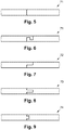
- FIGS. 5 and 6 show to a Teflon body 71, which is formed of a plurality of individual parts, which are connected by means of a hook blade rod-shaped together.
- the Fig. 5 shows the Teflon body 71 while in side view, the Fig. 6 in plan view. Due to the selected connection, the items are not only connected to each other, but it is also a kind of labyrinth seal is formed.
- Fig. 7 shows a Teflon body 72, which is formed of a plurality of individual parts, which are connected by means of a Studentsblattung rod-shaped.
- Fig. 8 shows a Teflon body 73 which is formed of a plurality of individual parts, which are connected to each other by means of a tongue and groove connection rod-shaped. In the Fig. 8 If the spring is incorporated directly into one of the individual lines, it would also be conceivable to use a foreign spring.
- Fig. 9 finally shows a Teflon body 74, which is formed of a plurality of individual parts, which are connected to each other by means of a dovetail connection rod-shaped.
- connection types shown several single rods are easily assembled into a longer rod.
- positive connections such as, for example, the hook blade ( Characters. 5 and 6 ) or the dovetail connection ( Fig. 9 ), since Teflon can be difficult to glue.
- Teflon body 70..74, 80 is formed of several individual parts, which are welded together. In this way, multiple single bars can seamlessly become a longer bar be joined together. This makes it possible to even better avoid possible leakage problems.
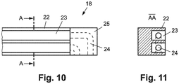
- FIGS. 10 and 11 now show how the seals 18 and 19 could be performed.
- the seal 18 is shown in Fig. 10 in bottom view and in Fig. 11 on average AA. Cavities 23 between the lips 22 of the multi-lip seal 18 are connected in this example, each with a drain 24, which is arranged in an edge piece 25 of the multi-lip seal 18.
- a particularly good drying of the metal strip 2 can be achieved because before the downstream in the direction of movement of the metal strip 2 lips 22 no liquid can accumulate long-term.
- the metal strip 2 thus becomes successively drier as the individual lips 22 pass.
- the multi-lip seal 18 may be made in one piece, or even consist of several parts.
- the edge piece 25 may be present as a separate part. It would also be conceivable that individual sealing lips 22 are inserted into a base body.
- FIGS. 10 to 11 an arrangement is shown which comprises a transverse to the direction of movement of the metal strip 2 multi-lip seal 18, which is in particular a means for applying a liquid to the metal strip 2 (eg spray nozzles in the cavity 15) downstream in the main direction of movement of the metal strip 2, wherein cavities 23rd between the lips 22 of the multi-lip seal 18 are connected to a drain 24.
- a liquid to the metal strip 2 eg spray nozzles in the cavity 15
- the embodiments show possible embodiments of an inventive arrangement / strip casting with a metal strip 2 and a sealing system 101 .. 108, with various combinations of the individual variants are possible with each other and this possibility of variation due to the teaching of technical action by objective invention in the ability of this technical Area professional.
- sealing systems 101..108 or arrangements in reality may also comprise more or fewer components than shown.
- sealing systems 101, 108 and / or arrangements, as well as their components have been shown partly out of scale and / or enlarged and / or reduced in size for a better understanding of their construction.
Landscapes
- Engineering & Computer Science (AREA)
- Mechanical Engineering (AREA)
- Sealing Devices (AREA)
- Specific Sealing Or Ventilating Devices For Doors And Windows (AREA)
- Tents Or Canopies (AREA)
Claims (10)
- Dispositif comprenant- une bande métallique mobile (2),- une cavité (14, 15) qui est délimitée sur un côté par la bande métallique (2),- un système d'étanchéité (101..108) entre la bande métallique (2) et au moins une paroi de délimitation (11, 12) de la cavité (14, 15), qui est disposé au niveau du bord de la bande métallique (2) et qui est orienté parallèlement à sa direction de déplacement, le système d'étanchéité (101.. 108)- comprenant un corps flexible allongé gonflable (3, 4),- un support (5, 6) dans lequel le corps gonflable (3, 4) mentionné est inséré et- un corps allongé (70..74, 80) en téflon, qui est disposé sur un côté du corps flexible gonflable (3, 4) opposé au support (5, 6) et qui touche la bande métallique (2) sur un côté opposé au corps gonflable (3, 4) avec une surface d'étanchéité (9, 10),caractérisé par- des lèvres d'étanchéité (18, 19) entre la bande métallique (2) et au moins une paroi de délimitation (11, 12) de la cavité en caoutchouc ou en silicone, qui sont orientées transversalement par rapport à une direction de déplacement de la bande métallique (2).
- Dispositif selon la revendication 1, caractérisé par un système d'alimentation en air comprimé (17) relié avec le corps gonflable (3, 4), qui est conçu pour alimenter le corps gonflable (3, 4) lors du fonctionnement avec une pression globalement constante.
- Dispositif selon la revendication 1 ou 2, caractérisé en ce que le corps en téflon (70..74, 80) est constitué de plusieurs détails qui sont emboîtés et/ou soudés entre eux.
- Dispositif selon l'une des revendications 1 à 3, caractérisé en ce que le corps en téflon (70..74, 80) est guidé de manière coulissante dans le support (5, 6) pour le corps gonflable (3, 4).
- Dispositif selon l'une des revendications 1 à 4, caractérisé en ce que le support (5, 6) est constitué d'un profilé en U.
- Dispositif selon l'une des revendications 1 à 5, caractérisé en ce que des systèmes d'étanchéité (103, 106) sont disposés de manière superposés entre eux sur un côté supérieur et un côté inférieur de la bande métallique (2).
- Dispositif selon la revendication 6, caractérisé en ce que les systèmes d'étanchéité (103, 106) disposés de manière superposés entre eux sont reliés de manière étanche entre eux.
- Dispositif selon la revendication 6 ou 7, caractérisé en ce que les deux systèmes d'étanchéité (103, 106) disposés de manière superposés entre eux disposent d'un corps gonflable (3, 4).
- Dispositif selon la revendication 6 ou 7, caractérisé en ce qu'un seul des deux systèmes d'étanchéité (103, 106) disposés de manière superposés entre eux dispose d'un corps gonflable (3, 4).
- Installation de moulage de bande comprenant un dispositif selon l'une des revendications 1 à 9 ainsi qu'un dispositif pour l'application d'un matériau sur la bande métallique (1).
Applications Claiming Priority (3)
| Application Number | Priority Date | Filing Date | Title |
|---|---|---|---|
| ATA50622/2012A AT513821A1 (de) | 2012-12-27 | 2012-12-27 | Dichtsystem für ein bewegtes Metallband sowie Bandgießanlage mit einem solchen Dichtsystem |
| US13/727,719 US20140186484A1 (en) | 2012-12-27 | 2012-12-27 | Sealing system for a moved metal strip as well as a strip casting installation with such a sealing system |
| PCT/AT2013/050257 WO2014100846A2 (fr) | 2012-12-27 | 2013-12-19 | Système d'étanchéité destiné à une bande métallique défilante et installation de coulée de bandes minces dotée d'un tel système d'étanchéité |
Publications (2)
| Publication Number | Publication Date |
|---|---|
| EP2938475A2 EP2938475A2 (fr) | 2015-11-04 |
| EP2938475B1 true EP2938475B1 (fr) | 2019-02-27 |
Family
ID=50156505
Family Applications (1)
| Application Number | Title | Priority Date | Filing Date |
|---|---|---|---|
| EP13831847.2A Active EP2938475B1 (fr) | 2012-12-27 | 2013-12-19 | Système d'étanchéité destiné à une bande métallique défilante et installation de coulée de bandes minces dotée d'un tel système d'étanchéité |
Country Status (3)
| Country | Link |
|---|---|
| EP (1) | EP2938475B1 (fr) |
| CN (1) | CN104884220B (fr) |
| WO (1) | WO2014100846A2 (fr) |
Family Cites Families (6)
| Publication number | Priority date | Publication date | Assignee | Title |
|---|---|---|---|---|
| FR2497828B1 (fr) * | 1981-01-09 | 1986-07-25 | Usinor | Dispositif d'etancheite pour machine de traitement de toles |
| DE3313406C3 (de) * | 1983-04-13 | 1994-02-24 | Hymmen Kg Theodor | Vorrichtung zum Aufbringen einer Flächenpressung auf fortschreitende Werkstücke |
| DE3417289A1 (de) * | 1984-05-10 | 1985-11-14 | Fa. Theodor Hymmen, 4800 Bielefeld | Vorrichtung zum aufbringen einer flaechenpressung auf fortschreitende werkstuecke |
| FI99035C (fi) * | 1995-11-03 | 1997-09-25 | Valmet Corp | Paperikoneen imutelan tiivisterakenne |
| CN101649447B (zh) * | 2009-08-26 | 2012-09-05 | 兰州大成科技股份有限公司 | 太阳能选择性吸收膜的连续卷绕镀膜装置 |
| JP5654607B2 (ja) * | 2009-12-11 | 2015-01-14 | サン−ゴバン パフォーマンス プラスティックス コーポレイション | ばね活性化動的封止アセンブリ用のシステム、方法および装置 |
-
2013
- 2013-12-19 WO PCT/AT2013/050257 patent/WO2014100846A2/fr active Application Filing
- 2013-12-19 EP EP13831847.2A patent/EP2938475B1/fr active Active
- 2013-12-19 CN CN201380068240.9A patent/CN104884220B/zh active Active
Non-Patent Citations (1)
| Title |
|---|
| None * |
Also Published As
| Publication number | Publication date |
|---|---|
| CN104884220B (zh) | 2017-03-15 |
| WO2014100846A2 (fr) | 2014-07-03 |
| EP2938475A2 (fr) | 2015-11-04 |
| CN104884220A (zh) | 2015-09-02 |
| WO2014100846A3 (fr) | 2015-04-09 |
Similar Documents
| Publication | Publication Date | Title |
|---|---|---|
| DE2726038C2 (de) | Elevator-Förderer für Schüttgut | |
| DE102014014895A1 (de) | Verfahren und Vorrichtung zur Herstellung von Bauteilen in einem Schichtbauverfahren | |
| EP1907209B1 (fr) | Machine pour produire des elements en forme de plaques en materiau composite | |
| DE1407909A1 (de) | Vorrichtung zum Reinigen von Gas | |
| DE3432553A1 (de) | Doppelgurtbandfoerderer | |
| DE2342618B1 (de) | Torfpresse | |
| EP2938475B1 (fr) | Système d'étanchéité destiné à une bande métallique défilante et installation de coulée de bandes minces dotée d'un tel système d'étanchéité | |
| DE1427640A1 (de) | Vorrichtung zum Bestreichen und Traenken von biegsamen Blaettern | |
| DE7622411U1 (de) | Vorrichtung zum kontinuierlichen aufrollen von gebaeckplaettchen | |
| AT513821A1 (de) | Dichtsystem für ein bewegtes Metallband sowie Bandgießanlage mit einem solchen Dichtsystem | |
| DE2453059B2 (de) | Dichteinrichtung an einem ueber- oder unterdruck aufweisenden behaelter | |
| DE4135613A1 (de) | Abdichteinrichtung fuer ein laufendes band | |
| DE102018117004B4 (de) | Einrichtung zur Förderung von Teig entlang einer Förderstrecke | |
| DE1905886A1 (de) | Gurtfoerderer | |
| DE102018117007B4 (de) | Einrichtung zur Förderung von Teig entlang einer Förderstrecke | |
| DE1629038B1 (de) | Abdichtvorrichtung fuer einen Trockner | |
| EP3619447B1 (fr) | Système joint d'étanchéité de bride et procédé de montage | |
| DE102009055689A1 (de) | Stückgutförderer mit einem Transportband | |
| DE2911760A1 (de) | Bandfilterpresse | |
| AT391304B (de) | Vorrichtung zum handhaben, insbesondere zum foerdern, von zumindest angenaehert vertikal ausgerichteten glasscheiben | |
| DE102015122882A1 (de) | Verfahren zum Bilden eines geschlossenen rahmenförmigen Abstandhalters für eine Isolierglasscheibe | |
| DE2010028A1 (de) | Verfahren und Vorrichtung zum Beleimen von Werkstucken | |
| DE2126457A1 (de) | Fördervorrichtung | |
| DE2741294C2 (de) | Waffelblattstreichmaschine | |
| DE102013015321B4 (de) | Verfahren zum kontinuierlichen Herstellen eines Endlosstranges aus Polyurethan-Reaktivkunststoff |
Legal Events
| Date | Code | Title | Description |
|---|---|---|---|
| PUAI | Public reference made under article 153(3) epc to a published international application that has entered the european phase |
Free format text: ORIGINAL CODE: 0009012 |
|
| 17P | Request for examination filed |
Effective date: 20150727 |
|
| AK | Designated contracting states |
Kind code of ref document: A2 Designated state(s): AL AT BE BG CH CY CZ DE DK EE ES FI FR GB GR HR HU IE IS IT LI LT LU LV MC MK MT NL NO PL PT RO RS SE SI SK SM TR |
|
| AX | Request for extension of the european patent |
Extension state: BA ME |
|
| DAX | Request for extension of the european patent (deleted) | ||
| 17Q | First examination report despatched |
Effective date: 20160502 |
|
| REG | Reference to a national code |
Ref country code: DE Ref legal event code: R079 Ref document number: 502013012330 Country of ref document: DE Free format text: PREVIOUS MAIN CLASS: B29C0041260000 Ipc: B29C0041280000 |
|
| GRAP | Despatch of communication of intention to grant a patent |
Free format text: ORIGINAL CODE: EPIDOSNIGR1 |
|
| STAA | Information on the status of an ep patent application or granted ep patent |
Free format text: STATUS: GRANT OF PATENT IS INTENDED |
|
| RIC1 | Information provided on ipc code assigned before grant |
Ipc: B23K 101/16 20060101ALI20180831BHEP Ipc: B29C 41/28 20060101AFI20180831BHEP Ipc: B29D 29/00 20060101ALI20180831BHEP Ipc: B29C 41/26 20060101ALI20180831BHEP |
|
| INTG | Intention to grant announced |
Effective date: 20181008 |
|
| GRAS | Grant fee paid |
Free format text: ORIGINAL CODE: EPIDOSNIGR3 |
|
| GRAA | (expected) grant |
Free format text: ORIGINAL CODE: 0009210 |
|
| STAA | Information on the status of an ep patent application or granted ep patent |
Free format text: STATUS: THE PATENT HAS BEEN GRANTED |
|
| AK | Designated contracting states |
Kind code of ref document: B1 Designated state(s): AL AT BE BG CH CY CZ DE DK EE ES FI FR GB GR HR HU IE IS IT LI LT LU LV MC MK MT NL NO PL PT RO RS SE SI SK SM TR |
|
| REG | Reference to a national code |
Ref country code: GB Ref legal event code: FG4D Free format text: NOT ENGLISH |
|
| REG | Reference to a national code |
Ref country code: CH Ref legal event code: EP |
|
| REG | Reference to a national code |
Ref country code: AT Ref legal event code: REF Ref document number: 1100680 Country of ref document: AT Kind code of ref document: T Effective date: 20190315 |
|
| REG | Reference to a national code |
Ref country code: IE Ref legal event code: FG4D Free format text: LANGUAGE OF EP DOCUMENT: GERMAN |
|
| REG | Reference to a national code |
Ref country code: DE Ref legal event code: R096 Ref document number: 502013012330 Country of ref document: DE |
|
| REG | Reference to a national code |
Ref country code: SE Ref legal event code: TRGR |
|
| REG | Reference to a national code |
Ref country code: NL Ref legal event code: MP Effective date: 20190227 |
|
| REG | Reference to a national code |
Ref country code: LT Ref legal event code: MG4D |
|
| PG25 | Lapsed in a contracting state [announced via postgrant information from national office to epo] |
Ref country code: FI Free format text: LAPSE BECAUSE OF FAILURE TO SUBMIT A TRANSLATION OF THE DESCRIPTION OR TO PAY THE FEE WITHIN THE PRESCRIBED TIME-LIMIT Effective date: 20190227 Ref country code: NO Free format text: LAPSE BECAUSE OF FAILURE TO SUBMIT A TRANSLATION OF THE DESCRIPTION OR TO PAY THE FEE WITHIN THE PRESCRIBED TIME-LIMIT Effective date: 20190527 Ref country code: LT Free format text: LAPSE BECAUSE OF FAILURE TO SUBMIT A TRANSLATION OF THE DESCRIPTION OR TO PAY THE FEE WITHIN THE PRESCRIBED TIME-LIMIT Effective date: 20190227 Ref country code: NL Free format text: LAPSE BECAUSE OF FAILURE TO SUBMIT A TRANSLATION OF THE DESCRIPTION OR TO PAY THE FEE WITHIN THE PRESCRIBED TIME-LIMIT Effective date: 20190227 Ref country code: PT Free format text: LAPSE BECAUSE OF FAILURE TO SUBMIT A TRANSLATION OF THE DESCRIPTION OR TO PAY THE FEE WITHIN THE PRESCRIBED TIME-LIMIT Effective date: 20190627 |
|
| PG25 | Lapsed in a contracting state [announced via postgrant information from national office to epo] |
Ref country code: RS Free format text: LAPSE BECAUSE OF FAILURE TO SUBMIT A TRANSLATION OF THE DESCRIPTION OR TO PAY THE FEE WITHIN THE PRESCRIBED TIME-LIMIT Effective date: 20190227 Ref country code: HR Free format text: LAPSE BECAUSE OF FAILURE TO SUBMIT A TRANSLATION OF THE DESCRIPTION OR TO PAY THE FEE WITHIN THE PRESCRIBED TIME-LIMIT Effective date: 20190227 Ref country code: IS Free format text: LAPSE BECAUSE OF FAILURE TO SUBMIT A TRANSLATION OF THE DESCRIPTION OR TO PAY THE FEE WITHIN THE PRESCRIBED TIME-LIMIT Effective date: 20190627 Ref country code: GR Free format text: LAPSE BECAUSE OF FAILURE TO SUBMIT A TRANSLATION OF THE DESCRIPTION OR TO PAY THE FEE WITHIN THE PRESCRIBED TIME-LIMIT Effective date: 20190528 Ref country code: LV Free format text: LAPSE BECAUSE OF FAILURE TO SUBMIT A TRANSLATION OF THE DESCRIPTION OR TO PAY THE FEE WITHIN THE PRESCRIBED TIME-LIMIT Effective date: 20190227 Ref country code: BG Free format text: LAPSE BECAUSE OF FAILURE TO SUBMIT A TRANSLATION OF THE DESCRIPTION OR TO PAY THE FEE WITHIN THE PRESCRIBED TIME-LIMIT Effective date: 20190527 |
|
| PG25 | Lapsed in a contracting state [announced via postgrant information from national office to epo] |
Ref country code: DK Free format text: LAPSE BECAUSE OF FAILURE TO SUBMIT A TRANSLATION OF THE DESCRIPTION OR TO PAY THE FEE WITHIN THE PRESCRIBED TIME-LIMIT Effective date: 20190227 Ref country code: EE Free format text: LAPSE BECAUSE OF FAILURE TO SUBMIT A TRANSLATION OF THE DESCRIPTION OR TO PAY THE FEE WITHIN THE PRESCRIBED TIME-LIMIT Effective date: 20190227 Ref country code: ES Free format text: LAPSE BECAUSE OF FAILURE TO SUBMIT A TRANSLATION OF THE DESCRIPTION OR TO PAY THE FEE WITHIN THE PRESCRIBED TIME-LIMIT Effective date: 20190227 Ref country code: CZ Free format text: LAPSE BECAUSE OF FAILURE TO SUBMIT A TRANSLATION OF THE DESCRIPTION OR TO PAY THE FEE WITHIN THE PRESCRIBED TIME-LIMIT Effective date: 20190227 Ref country code: RO Free format text: LAPSE BECAUSE OF FAILURE TO SUBMIT A TRANSLATION OF THE DESCRIPTION OR TO PAY THE FEE WITHIN THE PRESCRIBED TIME-LIMIT Effective date: 20190227 Ref country code: IT Free format text: LAPSE BECAUSE OF FAILURE TO SUBMIT A TRANSLATION OF THE DESCRIPTION OR TO PAY THE FEE WITHIN THE PRESCRIBED TIME-LIMIT Effective date: 20190227 Ref country code: SK Free format text: LAPSE BECAUSE OF FAILURE TO SUBMIT A TRANSLATION OF THE DESCRIPTION OR TO PAY THE FEE WITHIN THE PRESCRIBED TIME-LIMIT Effective date: 20190227 Ref country code: AL Free format text: LAPSE BECAUSE OF FAILURE TO SUBMIT A TRANSLATION OF THE DESCRIPTION OR TO PAY THE FEE WITHIN THE PRESCRIBED TIME-LIMIT Effective date: 20190227 |
|
| REG | Reference to a national code |
Ref country code: DE Ref legal event code: R097 Ref document number: 502013012330 Country of ref document: DE |
|
| PG25 | Lapsed in a contracting state [announced via postgrant information from national office to epo] |
Ref country code: SM Free format text: LAPSE BECAUSE OF FAILURE TO SUBMIT A TRANSLATION OF THE DESCRIPTION OR TO PAY THE FEE WITHIN THE PRESCRIBED TIME-LIMIT Effective date: 20190227 Ref country code: PL Free format text: LAPSE BECAUSE OF FAILURE TO SUBMIT A TRANSLATION OF THE DESCRIPTION OR TO PAY THE FEE WITHIN THE PRESCRIBED TIME-LIMIT Effective date: 20190227 |
|
| PLBE | No opposition filed within time limit |
Free format text: ORIGINAL CODE: 0009261 |
|
| STAA | Information on the status of an ep patent application or granted ep patent |
Free format text: STATUS: NO OPPOSITION FILED WITHIN TIME LIMIT |
|
| 26N | No opposition filed |
Effective date: 20191128 |
|
| PG25 | Lapsed in a contracting state [announced via postgrant information from national office to epo] |
Ref country code: SI Free format text: LAPSE BECAUSE OF FAILURE TO SUBMIT A TRANSLATION OF THE DESCRIPTION OR TO PAY THE FEE WITHIN THE PRESCRIBED TIME-LIMIT Effective date: 20190227 |
|
| PG25 | Lapsed in a contracting state [announced via postgrant information from national office to epo] |
Ref country code: TR Free format text: LAPSE BECAUSE OF FAILURE TO SUBMIT A TRANSLATION OF THE DESCRIPTION OR TO PAY THE FEE WITHIN THE PRESCRIBED TIME-LIMIT Effective date: 20190227 |
|
| REG | Reference to a national code |
Ref country code: CH Ref legal event code: PL |
|
| REG | Reference to a national code |
Ref country code: BE Ref legal event code: MM Effective date: 20191231 |
|
| PG25 | Lapsed in a contracting state [announced via postgrant information from national office to epo] |
Ref country code: MC Free format text: LAPSE BECAUSE OF FAILURE TO SUBMIT A TRANSLATION OF THE DESCRIPTION OR TO PAY THE FEE WITHIN THE PRESCRIBED TIME-LIMIT Effective date: 20190227 |
|
| PG25 | Lapsed in a contracting state [announced via postgrant information from national office to epo] |
Ref country code: LU Free format text: LAPSE BECAUSE OF NON-PAYMENT OF DUE FEES Effective date: 20191219 |
|
| PG25 | Lapsed in a contracting state [announced via postgrant information from national office to epo] |
Ref country code: LI Free format text: LAPSE BECAUSE OF NON-PAYMENT OF DUE FEES Effective date: 20191231 Ref country code: BE Free format text: LAPSE BECAUSE OF NON-PAYMENT OF DUE FEES Effective date: 20191231 Ref country code: CH Free format text: LAPSE BECAUSE OF NON-PAYMENT OF DUE FEES Effective date: 20191231 |
|
| PG25 | Lapsed in a contracting state [announced via postgrant information from national office to epo] |
Ref country code: CY Free format text: LAPSE BECAUSE OF FAILURE TO SUBMIT A TRANSLATION OF THE DESCRIPTION OR TO PAY THE FEE WITHIN THE PRESCRIBED TIME-LIMIT Effective date: 20190227 |
|
| PG25 | Lapsed in a contracting state [announced via postgrant information from national office to epo] |
Ref country code: HU Free format text: LAPSE BECAUSE OF FAILURE TO SUBMIT A TRANSLATION OF THE DESCRIPTION OR TO PAY THE FEE WITHIN THE PRESCRIBED TIME-LIMIT; INVALID AB INITIO Effective date: 20131219 Ref country code: MT Free format text: LAPSE BECAUSE OF FAILURE TO SUBMIT A TRANSLATION OF THE DESCRIPTION OR TO PAY THE FEE WITHIN THE PRESCRIBED TIME-LIMIT Effective date: 20190227 |
|
| PG25 | Lapsed in a contracting state [announced via postgrant information from national office to epo] |
Ref country code: MK Free format text: LAPSE BECAUSE OF FAILURE TO SUBMIT A TRANSLATION OF THE DESCRIPTION OR TO PAY THE FEE WITHIN THE PRESCRIBED TIME-LIMIT Effective date: 20190227 |
|
| PGFP | Annual fee paid to national office [announced via postgrant information from national office to epo] |
Ref country code: SE Payment date: 20230928 Year of fee payment: 11 |
|
| PGFP | Annual fee paid to national office [announced via postgrant information from national office to epo] |
Ref country code: GB Payment date: 20231107 Year of fee payment: 11 |
|
| PGFP | Annual fee paid to national office [announced via postgrant information from national office to epo] |
Ref country code: IE Payment date: 20231003 Year of fee payment: 11 Ref country code: FR Payment date: 20231107 Year of fee payment: 11 Ref country code: DE Payment date: 20231107 Year of fee payment: 11 Ref country code: AT Payment date: 20231114 Year of fee payment: 11 |