EP2937034B1 - Revêtement pour un dispositif d'endoscopie médicale - Google Patents
Revêtement pour un dispositif d'endoscopie médicale Download PDFInfo
- Publication number
- EP2937034B1 EP2937034B1 EP15169674.7A EP15169674A EP2937034B1 EP 2937034 B1 EP2937034 B1 EP 2937034B1 EP 15169674 A EP15169674 A EP 15169674A EP 2937034 B1 EP2937034 B1 EP 2937034B1
- Authority
- EP
- European Patent Office
- Prior art keywords
- cover
- projecting elements
- tip
- shaft
- medical
- Prior art date
- Legal status (The legal status is an assumption and is not a legal conclusion. Google has not performed a legal analysis and makes no representation as to the accuracy of the status listed.)
- Active
Links
- 230000000284 resting effect Effects 0.000 claims description 10
- 210000004209 hair Anatomy 0.000 claims description 8
- 238000000034 method Methods 0.000 description 44
- 210000001072 colon Anatomy 0.000 description 33
- 230000000112 colonic effect Effects 0.000 description 16
- 238000003780 insertion Methods 0.000 description 16
- 230000037431 insertion Effects 0.000 description 16
- 238000012800 visualization Methods 0.000 description 14
- 210000004877 mucosa Anatomy 0.000 description 12
- 210000000813 small intestine Anatomy 0.000 description 10
- 230000008901 benefit Effects 0.000 description 9
- 239000000463 material Substances 0.000 description 8
- 238000002560 therapeutic procedure Methods 0.000 description 8
- 208000037062 Polyps Diseases 0.000 description 7
- 238000002052 colonoscopy Methods 0.000 description 7
- 230000003902 lesion Effects 0.000 description 7
- 230000001154 acute effect Effects 0.000 description 5
- 210000000436 anus Anatomy 0.000 description 5
- 238000007689 inspection Methods 0.000 description 5
- 238000002627 tracheal intubation Methods 0.000 description 5
- 206010039897 Sedation Diseases 0.000 description 4
- 230000003211 malignant effect Effects 0.000 description 4
- 229920003023 plastic Polymers 0.000 description 4
- 238000001574 biopsy Methods 0.000 description 3
- 239000003795 chemical substances by application Substances 0.000 description 3
- 210000001198 duodenum Anatomy 0.000 description 3
- 229920001971 elastomer Polymers 0.000 description 3
- 239000012530 fluid Substances 0.000 description 3
- 238000011835 investigation Methods 0.000 description 3
- 239000000314 lubricant Substances 0.000 description 3
- 210000000713 mesentery Anatomy 0.000 description 3
- 239000004033 plastic Substances 0.000 description 3
- 230000036280 sedation Effects 0.000 description 3
- PEDCQBHIVMGVHV-UHFFFAOYSA-N Glycerine Chemical compound OCC(O)CO PEDCQBHIVMGVHV-UHFFFAOYSA-N 0.000 description 2
- XUIMIQQOPSSXEZ-UHFFFAOYSA-N Silicon Chemical compound [Si] XUIMIQQOPSSXEZ-UHFFFAOYSA-N 0.000 description 2
- 210000003484 anatomy Anatomy 0.000 description 2
- 230000015572 biosynthetic process Effects 0.000 description 2
- 230000036772 blood pressure Effects 0.000 description 2
- UUAGAQFQZIEFAH-UHFFFAOYSA-N chlorotrifluoroethylene Chemical group FC(F)=C(F)Cl UUAGAQFQZIEFAH-UHFFFAOYSA-N 0.000 description 2
- 238000001839 endoscopy Methods 0.000 description 2
- 230000002209 hydrophobic effect Effects 0.000 description 2
- 210000003405 ileum Anatomy 0.000 description 2
- 230000006872 improvement Effects 0.000 description 2
- 208000014674 injury Diseases 0.000 description 2
- 210000002429 large intestine Anatomy 0.000 description 2
- 239000000203 mixture Substances 0.000 description 2
- 239000004417 polycarbonate Substances 0.000 description 2
- 229920000515 polycarbonate Polymers 0.000 description 2
- 229920000642 polymer Polymers 0.000 description 2
- 238000011084 recovery Methods 0.000 description 2
- 239000005060 rubber Substances 0.000 description 2
- 229910052710 silicon Inorganic materials 0.000 description 2
- 239000010703 silicon Substances 0.000 description 2
- 210000002784 stomach Anatomy 0.000 description 2
- 210000001519 tissue Anatomy 0.000 description 2
- 230000008733 trauma Effects 0.000 description 2
- 230000000007 visual effect Effects 0.000 description 2
- 201000004569 Blindness Diseases 0.000 description 1
- 241000252983 Caecum Species 0.000 description 1
- 206010009192 Circulatory collapse Diseases 0.000 description 1
- 244000043261 Hevea brasiliensis Species 0.000 description 1
- 206010021143 Hypoxia Diseases 0.000 description 1
- CERQOIWHTDAKMF-UHFFFAOYSA-M Methacrylate Chemical compound CC(=C)C([O-])=O CERQOIWHTDAKMF-UHFFFAOYSA-M 0.000 description 1
- 206010028980 Neoplasm Diseases 0.000 description 1
- 229920005439 Perspex® Polymers 0.000 description 1
- 229920002614 Polyether block amide Polymers 0.000 description 1
- 206010041649 Splenic injury Diseases 0.000 description 1
- 208000025865 Ulcer Diseases 0.000 description 1
- 239000000654 additive Substances 0.000 description 1
- 239000000560 biocompatible material Substances 0.000 description 1
- 230000000740 bleeding effect Effects 0.000 description 1
- 210000004204 blood vessel Anatomy 0.000 description 1
- 201000011510 cancer Diseases 0.000 description 1
- 230000002802 cardiorespiratory effect Effects 0.000 description 1
- 239000004359 castor oil Substances 0.000 description 1
- 235000019438 castor oil Nutrition 0.000 description 1
- 210000004534 cecum Anatomy 0.000 description 1
- 230000008859 change Effects 0.000 description 1
- 238000006243 chemical reaction Methods 0.000 description 1
- 150000001875 compounds Chemical group 0.000 description 1
- 239000004035 construction material Substances 0.000 description 1
- 230000036461 convulsion Effects 0.000 description 1
- 238000005520 cutting process Methods 0.000 description 1
- 238000002574 cystoscopy Methods 0.000 description 1
- 230000006378 damage Effects 0.000 description 1
- 238000001514 detection method Methods 0.000 description 1
- 238000011161 development Methods 0.000 description 1
- 238000003745 diagnosis Methods 0.000 description 1
- 238000006073 displacement reaction Methods 0.000 description 1
- 239000003814 drug Substances 0.000 description 1
- 229940079593 drug Drugs 0.000 description 1
- 230000000694 effects Effects 0.000 description 1
- 239000000806 elastomer Substances 0.000 description 1
- 239000013536 elastomeric material Substances 0.000 description 1
- 238000005516 engineering process Methods 0.000 description 1
- 230000002708 enhancing effect Effects 0.000 description 1
- 238000009541 flexible sigmoidoscopy Methods 0.000 description 1
- 210000001035 gastrointestinal tract Anatomy 0.000 description 1
- 238000002575 gastroscopy Methods 0.000 description 1
- 235000011187 glycerol Nutrition 0.000 description 1
- ZEMPKEQAKRGZGQ-XOQCFJPHSA-N glycerol triricinoleate Natural products CCCCCC[C@@H](O)CC=CCCCCCCCC(=O)OC[C@@H](COC(=O)CCCCCCCC=CC[C@@H](O)CCCCCC)OC(=O)CCCCCCCC=CC[C@H](O)CCCCCC ZEMPKEQAKRGZGQ-XOQCFJPHSA-N 0.000 description 1
- 230000036541 health Effects 0.000 description 1
- 239000011796 hollow space material Substances 0.000 description 1
- 239000000017 hydrogel Substances 0.000 description 1
- 230000007954 hypoxia Effects 0.000 description 1
- 238000011065 in-situ storage Methods 0.000 description 1
- 238000009434 installation Methods 0.000 description 1
- 206010022694 intestinal perforation Diseases 0.000 description 1
- 238000001990 intravenous administration Methods 0.000 description 1
- 210000001630 jejunum Anatomy 0.000 description 1
- 208000018769 loss of vision Diseases 0.000 description 1
- 231100000864 loss of vision Toxicity 0.000 description 1
- 238000012423 maintenance Methods 0.000 description 1
- 238000004519 manufacturing process Methods 0.000 description 1
- 238000012986 modification Methods 0.000 description 1
- 230000004048 modification Effects 0.000 description 1
- 229920003052 natural elastomer Polymers 0.000 description 1
- 229920001194 natural rubber Polymers 0.000 description 1
- 210000005036 nerve Anatomy 0.000 description 1
- 239000003921 oil Substances 0.000 description 1
- 235000019198 oils Nutrition 0.000 description 1
- 239000004006 olive oil Substances 0.000 description 1
- 235000008390 olive oil Nutrition 0.000 description 1
- 210000000056 organ Anatomy 0.000 description 1
- -1 polychlorpropene Polymers 0.000 description 1
- 229920013636 polyphenyl ether polymer Polymers 0.000 description 1
- 229920001296 polysiloxane Polymers 0.000 description 1
- 229920002635 polyurethane Polymers 0.000 description 1
- 239000004814 polyurethane Substances 0.000 description 1
- 238000003825 pressing Methods 0.000 description 1
- 230000008569 process Effects 0.000 description 1
- 210000000664 rectum Anatomy 0.000 description 1
- 230000009467 reduction Effects 0.000 description 1
- 238000009877 rendering Methods 0.000 description 1
- 238000012958 reprocessing Methods 0.000 description 1
- 239000000523 sample Substances 0.000 description 1
- 238000004904 shortening Methods 0.000 description 1
- 239000007787 solid Substances 0.000 description 1
- 239000000126 substance Chemical group 0.000 description 1
- 229920002725 thermoplastic elastomer Polymers 0.000 description 1
- 230000036269 ulceration Effects 0.000 description 1
- 230000004393 visual impairment Effects 0.000 description 1
Images


Classifications
-
- A—HUMAN NECESSITIES
- A61—MEDICAL OR VETERINARY SCIENCE; HYGIENE
- A61B—DIAGNOSIS; SURGERY; IDENTIFICATION
- A61B1/00—Instruments for performing medical examinations of the interior of cavities or tubes of the body by visual or photographical inspection, e.g. endoscopes; Illuminating arrangements therefor
- A61B1/00131—Accessories for endoscopes
- A61B1/00135—Oversleeves mounted on the endoscope prior to insertion
-
- A—HUMAN NECESSITIES
- A61—MEDICAL OR VETERINARY SCIENCE; HYGIENE
- A61B—DIAGNOSIS; SURGERY; IDENTIFICATION
- A61B1/00—Instruments for performing medical examinations of the interior of cavities or tubes of the body by visual or photographical inspection, e.g. endoscopes; Illuminating arrangements therefor
- A61B1/00142—Instruments for performing medical examinations of the interior of cavities or tubes of the body by visual or photographical inspection, e.g. endoscopes; Illuminating arrangements therefor with means for preventing contamination, e.g. by using a sanitary sheath
-
- A—HUMAN NECESSITIES
- A61—MEDICAL OR VETERINARY SCIENCE; HYGIENE
- A61B—DIAGNOSIS; SURGERY; IDENTIFICATION
- A61B1/00—Instruments for performing medical examinations of the interior of cavities or tubes of the body by visual or photographical inspection, e.g. endoscopes; Illuminating arrangements therefor
- A61B1/00064—Constructional details of the endoscope body
- A61B1/00071—Insertion part of the endoscope body
- A61B1/00075—Insertion part of the endoscope body with externally roughened shaft
-
- A—HUMAN NECESSITIES
- A61—MEDICAL OR VETERINARY SCIENCE; HYGIENE
- A61B—DIAGNOSIS; SURGERY; IDENTIFICATION
- A61B1/00—Instruments for performing medical examinations of the interior of cavities or tubes of the body by visual or photographical inspection, e.g. endoscopes; Illuminating arrangements therefor
- A61B1/00064—Constructional details of the endoscope body
- A61B1/00071—Insertion part of the endoscope body
- A61B1/0008—Insertion part of the endoscope body characterised by distal tip features
- A61B1/00089—Hoods
-
- A—HUMAN NECESSITIES
- A61—MEDICAL OR VETERINARY SCIENCE; HYGIENE
- A61B—DIAGNOSIS; SURGERY; IDENTIFICATION
- A61B1/00—Instruments for performing medical examinations of the interior of cavities or tubes of the body by visual or photographical inspection, e.g. endoscopes; Illuminating arrangements therefor
- A61B1/00064—Constructional details of the endoscope body
- A61B1/00071—Insertion part of the endoscope body
- A61B1/0008—Insertion part of the endoscope body characterised by distal tip features
- A61B1/00101—Insertion part of the endoscope body characterised by distal tip features the distal tip features being detachable
-
- A—HUMAN NECESSITIES
- A61—MEDICAL OR VETERINARY SCIENCE; HYGIENE
- A61B—DIAGNOSIS; SURGERY; IDENTIFICATION
- A61B1/00—Instruments for performing medical examinations of the interior of cavities or tubes of the body by visual or photographical inspection, e.g. endoscopes; Illuminating arrangements therefor
- A61B1/00131—Accessories for endoscopes
- A61B1/00137—End pieces at either end of the endoscope, e.g. caps, seals or forceps plugs
-
- A—HUMAN NECESSITIES
- A61—MEDICAL OR VETERINARY SCIENCE; HYGIENE
- A61B—DIAGNOSIS; SURGERY; IDENTIFICATION
- A61B1/00—Instruments for performing medical examinations of the interior of cavities or tubes of the body by visual or photographical inspection, e.g. endoscopes; Illuminating arrangements therefor
- A61B1/00147—Holding or positioning arrangements
- A61B1/00148—Holding or positioning arrangements using anchoring means
-
- A—HUMAN NECESSITIES
- A61—MEDICAL OR VETERINARY SCIENCE; HYGIENE
- A61B—DIAGNOSIS; SURGERY; IDENTIFICATION
- A61B1/00—Instruments for performing medical examinations of the interior of cavities or tubes of the body by visual or photographical inspection, e.g. endoscopes; Illuminating arrangements therefor
- A61B1/00147—Holding or positioning arrangements
- A61B1/00154—Holding or positioning arrangements using guiding arrangements for insertion
-
- A—HUMAN NECESSITIES
- A61—MEDICAL OR VETERINARY SCIENCE; HYGIENE
- A61B—DIAGNOSIS; SURGERY; IDENTIFICATION
- A61B1/00—Instruments for performing medical examinations of the interior of cavities or tubes of the body by visual or photographical inspection, e.g. endoscopes; Illuminating arrangements therefor
- A61B1/005—Flexible endoscopes
- A61B1/01—Guiding arrangements therefore
-
- A—HUMAN NECESSITIES
- A61—MEDICAL OR VETERINARY SCIENCE; HYGIENE
- A61B—DIAGNOSIS; SURGERY; IDENTIFICATION
- A61B1/00—Instruments for performing medical examinations of the interior of cavities or tubes of the body by visual or photographical inspection, e.g. endoscopes; Illuminating arrangements therefor
- A61B1/012—Instruments for performing medical examinations of the interior of cavities or tubes of the body by visual or photographical inspection, e.g. endoscopes; Illuminating arrangements therefor characterised by internal passages or accessories therefor
- A61B1/015—Control of fluid supply or evacuation
-
- A—HUMAN NECESSITIES
- A61—MEDICAL OR VETERINARY SCIENCE; HYGIENE
- A61B—DIAGNOSIS; SURGERY; IDENTIFICATION
- A61B1/00—Instruments for performing medical examinations of the interior of cavities or tubes of the body by visual or photographical inspection, e.g. endoscopes; Illuminating arrangements therefor
- A61B1/31—Instruments for performing medical examinations of the interior of cavities or tubes of the body by visual or photographical inspection, e.g. endoscopes; Illuminating arrangements therefor for the rectum, e.g. proctoscopes, sigmoidoscopes, colonoscopes
-
- A—HUMAN NECESSITIES
- A61—MEDICAL OR VETERINARY SCIENCE; HYGIENE
- A61B—DIAGNOSIS; SURGERY; IDENTIFICATION
- A61B1/00—Instruments for performing medical examinations of the interior of cavities or tubes of the body by visual or photographical inspection, e.g. endoscopes; Illuminating arrangements therefor
- A61B1/32—Devices for opening or enlarging the visual field, e.g. of a tube of the body
-
- A—HUMAN NECESSITIES
- A61—MEDICAL OR VETERINARY SCIENCE; HYGIENE
- A61M—DEVICES FOR INTRODUCING MEDIA INTO, OR ONTO, THE BODY; DEVICES FOR TRANSDUCING BODY MEDIA OR FOR TAKING MEDIA FROM THE BODY; DEVICES FOR PRODUCING OR ENDING SLEEP OR STUPOR
- A61M25/00—Catheters; Hollow probes
- A61M25/01—Introducing, guiding, advancing, emplacing or holding catheters
- A61M25/02—Holding devices, e.g. on the body
- A61M25/04—Holding devices, e.g. on the body in the body, e.g. expansible
-
- A—HUMAN NECESSITIES
- A61—MEDICAL OR VETERINARY SCIENCE; HYGIENE
- A61M—DEVICES FOR INTRODUCING MEDIA INTO, OR ONTO, THE BODY; DEVICES FOR TRANSDUCING BODY MEDIA OR FOR TAKING MEDIA FROM THE BODY; DEVICES FOR PRODUCING OR ENDING SLEEP OR STUPOR
- A61M29/00—Dilators with or without means for introducing media, e.g. remedies
-
- A—HUMAN NECESSITIES
- A61—MEDICAL OR VETERINARY SCIENCE; HYGIENE
- A61M—DEVICES FOR INTRODUCING MEDIA INTO, OR ONTO, THE BODY; DEVICES FOR TRANSDUCING BODY MEDIA OR FOR TAKING MEDIA FROM THE BODY; DEVICES FOR PRODUCING OR ENDING SLEEP OR STUPOR
- A61M25/00—Catheters; Hollow probes
- A61M25/0043—Catheters; Hollow probes characterised by structural features
- A61M2025/006—Catheters; Hollow probes characterised by structural features having a special surface topography or special surface properties, e.g. roughened or knurled surface
Definitions
- the present disclosure relates to a covering or sheath or sleeve or cuff having external projections for use with a medical device and in particular for use with flexible medical scoping devices such as endoscopes or enteroscopes.
- the disclosure includes inter alia use of the disposable removable covering in methods of medical scoping procedures or examinations, particularly but not exclusively, where the site is the colon or small intestine.
- the disclosure also includes a kit including an applicator for assisting in placing the covering about or over a medical scoping device.
- flexible instruments designed to view the gastrointestinal tract are inserted along a body cavity to an internal part such as the stomach, duodenum, small intestine or large intestine.
- the instruments are provided with fibre-optic or charge-couple device (CCD) cameras which enable images to be transmitted around bends and images to be produced to displays on a television screen. Accordingly, it is possible to view the inside surfaces of the oesophagus, stomach and duodenum using a gastroscope, the small intestine with an enteroscope, part of the colon using a flexible sigmoidoscope and the whole of the large intestine (the bowel) with a colonoscope.
- CCD charge-couple device
- Enteroscopy is the endoscopic examination of the small intestine whereas colonoscopy is the endoscopic examination of the colon and the distal part of the small bowel and flexible sigmoidoscopy is the examination of the rectum and lower part of the bowel.
- Each scoping procedure may provide a visual diagnosis (e.g. ulceration, polyps) and grants the opportunity for biopsy or removal of suspected lesions.
- colonoscopic and enteroscopic examinations are the most effective techniques to assess the state of health of the bowel, they are inconvenient, uncomfortable, expensive procedures that are associated with significant risks of potentially serious complications.
- a further disadvantage of colonoscopic and enteroscopic procedures is that they are time consuming for patients and medical personnel alike, the procedure can take anywhere from 20 minutes to 2 hours depending on how difficult it is to advance a scope through the colon or small intestine.
- the colonoscopy itself takes around thirty minutes to perform but in some cases may require up to an hour, and for the patient, there is a recovery period of up to two hours in hospital whilst sedation passes off and over that time clinical observation is needed.
- the number of clinically competent personnel required to conduct a colonoscopic procedure are an endoscopist specialist and three assistants including the person responsible for reprocessing the equipment. In addition, staffing is required for the recovery area.
- the position of the tip of may be difficult to maintain from the moment at which a lesion or polyp is detected to the completion of any therapeutic procedure.
- the tip does not travel back at a constant speed but rather with jerks and slippages particularly when traversing a bend or length of colon where the bowel has been concertinaed over the endoscope shaft during intubation.
- the tip of the device may, at any moment, slip backwards thereby causing the clinician to lose position. If tip position is lost, the clinician is required to relocate the lesion or polyp for the therapeutic procedure to be continued.
- the colonoscopic procedure is not simple because the bowel is long and convoluted. In places it is tethered by peritoneal bands and in others it lies relatively free.
- the tip of the endoscope encounters a tight bend the free part of the colon "loops" as more of the endoscope is introduced and so looping occurs in the free part of the colon before the bend when there is difficulty negotiating the bend.
- This leads to stretching of the mesentery of the loop (the tissue that carries the nerves and blood vessels to the bowel). If the stretching is continued or severe while the endoscopist pushes round the bend, the patient experiences pain the blood pressure falls and the pulse slows.
- Loop formation is the main cause of failure or delay in completing an examination. It is responsible for the pain experienced by the patient and the need for heavy sedation that in turn leads to cardio-respiratory complications. It is also the major cause of perforation in patients not undergoing a therapeutic procedure.
- An improved medical scoping device that could reduce the time taken for the colonoscopist or enteroscopist to perform the procedure would offer immediate advantages to patients and clinicians alike.
- An improved medical scoping device that could reduce the risk of complications during a procedure would offer immediate advantages to patients and clinicians alike.
- a medical scoping device that could improve endoscopic intubation, extubation and visualisation of the large bowel would offer immediate advantages to both patients and clinicians alike.
- a medical scoping device that could reduce loss of tip position during a medical procedure would offer immediate advantages to both patients and clinicians alike.
- An improved medical scoping device that could reduce the requirement or level of sedation for a patient would offer immediate advantages to both patients and clinicians alike.
- An improved medical scoping device that could overcome the problems associated with looping and so reduce discomfort to the person on whom the procedure was being performed, would offer immediate advantages to patients and clinicians alike.
- US4207872 discloses a device and method for advancing an endoscope through a body passage.
- the device includes a sleeve having an annular chamber defined in part by an outer wall of elastomeric material.
- a multiplicity of resilient hollow protrusions are formed in the wall and expand outwardly and rearwardly when the chamber is filled with a suitable fluid under pressure and which retract inwardly and forwardly when the pressure of the fluid is reduced.
- the device extends about and is secured to the distal end portion of an endoscope.
- JP20003033319A discloses an auxiliary instrument for insertion into an endoscope. The instrument is capable of improving the insertion.
- a plurality of auxiliary instruments are arranged around an endoscope.
- the auxiliary instrument includes a fin-shaped protruding part formed of a flexible member having flexibility such as rubber on the side of a leading end of tubular member.
- the auxiliary instrument for insertion is arranged for installation in predetermined position on the endoscope.
- JP2003180611A discloses an insertion aid for an endoscope.
- the aid for assisting the insertion of the endoscope is constituted of a soft tubular member to be mounted on the endoscope insertion section and a plurality of soft and flat fin-shaped protrusions having a thin wall which protrude obliquely backward from the outer surface of the soft tubular member with respect to the insertion direction of the endoscope into the lumen.
- the fin-shaped protrusions are curled and turned over when the endoscope insertion section is pulled and the back surfaces abut with the wall of the lumen, thus holding the position of the endoscope insertion section within the lumen.
- JP2003339631A discloses an endoscope insertion assisting tool.
- the endoscope insertion assisting tool comprises a fixing part and four protrusion parts in the form of fins.
- the fixing part is mounted on the endoscope insertion part.
- the four protrusion parts are in the shape of soft and flat thin plates and project from the outer surface of the fixing part at a prescribed angle obliquely backward with respect to an inserting direction into a body cavity tube.
- Each protrusion part comprises a hard part and a soft part provided at a part of its periphery.
- a cover for a colonoscope shaft comprising an elongate tubular member and being arranged for application over the colonoscope shaft with the cover extending along at least a part of the length of a distal end of the shaft, the tubular member comprising an inner surface at least a part of which grips the shaft and holds the cover in place and an outer surface comprising a plurality of spaced projecting elements having a tip and a base that are moveable between a resting position to a position wherein the tip of the projecting element is substantially parallel to a longitudinal axis of the colonoscope and to a position that is at an angle that is approximately perpendicular to the longitudinal axis of the colonoscope shaft so that the said projecting elements are fanned out to contact with and provide support for and to dilate a lumen wall of a body passage into which the medical scoping device has been inserted; wherein the projecting elements are arranged as at least one ring running circumferentially around the cover, where
- a medical scoping device comprising an air suction means for removing air from a body passage, an elongate flexible shaft having a proximal end associated with a viewing means and a distal end, the medical scoping device further comprising the cover of the present invention releasably attached thereto and covering at least a part of the shaft at its distal end.
- a cover according to the present invention or a medical scoping device for use in a scoping procedure is also disclosed.
- an applicator for attaching a cover to a shaft of a medical scoping device, the applicator comprising a pair of complimentarily mated casings each sized and shaped so as to accommodate a cover for a medical scoping device therein, each casing further comprising an engaging means for releasably engaging the casings to one another and each casing comprising at least one securing means for securing a proximal end of the said cover thereto.
- kit comprising at least one cover and an applicator, optionally the kit further includes a medical scoping device and/or a cutting means and/or a distal end cap.
- a method of avoiding looping in a medical scoping procedure comprising inserting a medical scoping device shaft having an air suction means for removing air from a body passage into an orifice of an individual under investigation, the medical scoping device further comprising a cover releasably attached to the medical scoping device shaft and covering at least a part of the shaft at its distal end, wherein the cover comprises an elongate tubular member having an inner surface at least a part of which grips the shaft and acts to hold the cover in place and an outer surface comprising a plurality of spaced projecting elements, and wherein when advancing the medical scoping device into the patient's bowel or small intestine and the distal end encounters a bend or loop in the patient's bowel or small intestine, the medical scoping device is withdrawn towards its proximal end causing the projecting elements to splay or fan out and to dilate the lumen of the bowel or small intestine whilst holding the medical scoping device in
- a method of maintaining tip position and improving tip control during an examination essentially comprising the steps of the first method above wherein the projecting elements maintain the medical scoping device tip in a central part of the bowel lumen as the device moves in a proximal direction thereby holding the mucosa to prevent the tip from flipping backwards so as to maintain position during therapy.
- a “medical scoping device” is intended to refer to endoscopes, enteroscopes, sigmiodoscopes, gastroscopes, colonoscopes and panendoscopes and is used interchangeably and is intended to include all scoping instruments whether passed directly or through a cannula into a body/organ/tissue cavity.
- Endoscopy involves the inspection of the inside of the body or body cavity and includes arthroscopy, cystoscopy, gastroscopy, uteroscopy and colonoscopy whereas enteroscopy is the examination of the small intestine including the duodenum, jejunum, and ileum.
- the scopes are elongate flexible probes and it is intended that the covers may be used in conjunction with all of the aforementioned scopes.
- a "medical scoping procedure” is intended to include any medical procedure or examination that involves use of a medical scoping device as hereinbefore described.
- the distal end the cover is the end which is commensurate with the distal end of the medical scoping device shaft which comprises lenses, channels such as air suction conduits and light guides. It is the end which is furthest from the endoscopist/ colonoscopist and as such is the end of the instrument which is deepest within the patient's body and therefore it is the end which will first come into contact with a looped segment of the bowel. Accordingly, a distal movement of the endoscope is a forward movement i.e. further into a patient's bowel.
- proximal end of the sheath is the end which is commensurate with the proximal end of the endoscope and which is the end situated nearest the operator and therefore a proximal movement of the endoscope is a backward movement towards the operator.
- the medical scoping device cover provides an improved means of conducting probing procedures, avoiding the problems associated with looping and generally improving the speed and comfort of the procedure for the patient.
- the cover is arranged for application over the medical scoping device shaft so as to surround it and to extend along at least a distal part or tip region of the shaft.
- the cover comprises an inner surface at least a part of which grips the shaft of the medical device and holds the cover in place against movement longitudinally of the shaft during displacement of the shaft through a body passage into which the shaft is inserted in use, and the outer surface of the sleeve is provided with protrusions configured to cover the endoscope shaft onto which the cover is applied whereby the protrusions when fanned out or extended from the shaft body provide a means for gently holding on to or gripping the inner surface of the body passage and opening up the lumen.
- the gripping of the body passage by the projecting elements is enhanced by removal of any air in the body passage so that the wall of the body passage into which the medical device has been inserted collapses on to the projecting elements and is drawn into the spaces between the projecting elements thus the body passage walls are held against the cover and a rearward or proximal movement of the device causes the body passage to concertina behind the gripped portion of the body passage, the scope to straighten and the lumen ahead of the distal end to straighten and open up.
- the at least a part of an inner surface of the cover that is in contact with the distal end of the medical scoping device shaft may either be upper and lower end regions of the cover or the entire inner surface.
- the elongate tubular member may comprise a contiguous tubular member or alternatively it may be provided with slits or gaps or ridges running in a longitudinal direction commensurate with the longitudinal axis of the medical scoping device.
- the number of slits is directly proportional to the number of projecting elements, the projecting elements being positioned in the slits or gaps between the solid parts of the cover.
- the projecting elements are in the form of bristles, spikes, spines, fins, wedges, paddles or cones and are arranged to extend outwardly and away from the outer surface of the elongate tubular member.
- the projecting elements may be cylindrical, conical or tapered and the tips of the projecting elements may either be rounded or blunted.
- the projecting elements may be formed integrally with the outer surface of the elongate tubular member or alternatively they may be attached or moulded thereto.
- the cover is provided with longitudinal slits or gaps then the projecting elements may be provided attached to or moulded in between adjacent slits or gaps.
- the bases of the projecting elements may be hinged onto the outer surface of the elongate tubular member.
- the projecting elements are hinged and capable of moving between a resting position, where the tips extend away from the scoping device shaft at a selected angle, to a position wherein the tips of the projecting elements are substantially parallel to a longitudinal axis of the enteroscope/endoscope shaft and also to a position wherein the projecting elements project outwards from the enteroscope/endoscope shaft at an angle of less than or equal to perpendicular to the longitudinal axis of the medical scoping device shaft. In this position the projecting elements can be said to be fanned out.
- the projecting elements are attached at their base to circumferentially positioned cross members situated below the level of the outer surface of the casing to form a hinge.
- the projecting elements are hinged and capable of moving between a resting position, where the tips extend away from the scoping device shaft at a selected angle, to a position wherein the tips of the projecting elements are substantially parallel to a longitudinal axis of the enteroscope/endoscope shaft an fall below the level of the outer surface of the casing and also to a position wherein the projecting elements project outwards from the enteroscope/endoscope shaft at an angle of less than or equal to perpendicular to the longitudinal axis of the medical scoping device shaft. In this position the projecting elements can be said to be fanned out.
- the tips of the projecting elements when in a position of being substantially parallel to the longitudinal axis of the medical scoping device may either be directed towards a distal or proximal end of the covered medical scoping device.
- the projecting elements can be said to be moveable between at least three, and in some arrangements, four positions. In a first position the projecting elements project at a selected acute angle away from the longitudinal axis of the medical scoping device, this is the "resting position".
- the projecting elements are moveable beyond the third position and flick over at a critical point so that the tips point towards the distal end of the scoping medical device, this is the fourth position, and is the position in which the medical scoping device can be withdrawn through the orifice into which it was initially inserted.
- the cover may be provided with a projecting elements closure means optionally in the form of a sleeve which can be drawn from a distal to a proximal end and which flattens the projecting elements from the third or resting position to the second position described above.
- the covers are preferably provided with a projecting element closure means that moves the projecting elements from a fanned out position to a position where they are substantially parallel to the longitudinal axis of the shaft of the medical scoping device.
- the projecting elements closure means is in the form of a sleeve that is capable of being drawn over the projecting elements.
- the projecting elements closure means is provided with a draw string or the like which allows the sleeve to unfurl in a proximal direction.
- the bases of the moulded projecting elements are raised so that they form a bump or bulge on the outer surface of the elongate tubular member under which is an air pocket.
- the projecting elements are hinged or moveable about their bases to enable them to be moveable and in one arrangement to flick over beyond a critical point of maximum flexion so that the tips point distally to allow for a smooth removal of the medical device from the body passage and orifice into which the device has been inserted.
- the bases of the moulded elements are attached at their base to circumferentially positioned cross members.
- the projecting elements are hinged or moveable about their bases to flick over beyond a critical point of maximum flexion so that the tips point distally to allow for a smooth removal of the medical device from the body passage and orifice into which the device has been inserted.
- the hinges at the bases of the projecting elements facilitate movement of the projecting elements between a resting position at an acute angle, preferably between 85 to 35° and more preferably about 55 to 75° in addition to a tendency to collapse to the second position i.e. one that is substantially parallel to the horizontal access.
- the hinges also facilitate a tendency to resist flexion to a point substantially perpendicular to the longitudinal axis (90°) and a tendency to flatten to an obtuse angle i.e. flipping over to about 170 - 180° upon extubation after a critical angle is exceeded.
- the hinges maybe of variable stiffness.
- the bristles are between 4 to 20 mm in length from base to tip and more preferably they are between 4 to 15 mm in length and more preferably still are between 4 to10 mm in length.
- the length of the bristles is marginally shorter at either or both the distal and proximal ends of the cover.
- the central region of the cover comprises bristles of a longer length so that the bristles of the cover when seen in side view are elliptical.
- the projecting elements that are of a longer length are more flexible and are constructed of a softer material than projecting elements of a shorter length and more preferably still the longer projecting elements are everted.
- the projecting elements are in the form of bristles or hairs the diameter of the projecting element is between 0.5 to 3.0 mm and preferably is about 1.5 mm.
- the projecting elements may be either straight or curved.
- Projecting elements with a slight curve offer the advantage of when they abut or contact the colonic wall there is a tendency to deform, so that the tip of the projecting element bends out rather than pressing into or impinging onto the colonic wall causing trauma.
- the slight curve reveals the under surface of the projecting elements into the colonic wall, pushing it away and flattening folds as they pass by.
- the elongate tubular member and the projecting elements are constructed of a suitable biocompatible material so that they are flexible and resiliently deformable, suitable materials include but are not limited to a material selected from the group comprising polymers, plastics, elastomers and rubbers. Suitable examples include polyurethane, polychlorpropene, natural rubber, silicon and silicon elastomeric materials a particularly preferred material is a thermoplastic elastomer for example and without limitation Pebax®.
- the elongate tubular member and projecting elements are constructed from the same or differing materials, from a manufacturing perspective a cover comprising the same construction material is preferred however it is within the scope of the invention to construct the projecting elements from a different material to the elongate tubular member's main body.
- the projecting elements in a resting position are acutely angled with respect to the central longitudinal axis of the cover and more preferably the projecting elements are positioned at an angle of between 35° to 85° with respect to a central longitudinal axis of a central line of the cover, more preferably they are angled at about 55° to 75° from the cover's central longitudinal axis.
- the projecting elements are positioned in rings running circumferentially around the cover and along the length of the cover. Ideally, there is at least one or more rings and more ideally two rings and in other arrangements up to 20 rings. It will be appreciated that the projecting elements may, in some embodiments, be provided as a single ring.
- each ring comprises between 4 to 16 projecting elements and more preferably between 5 to 10 projecting elements.
- the rings of projecting elements may be aligned uniformly in parallel descending the length of the cover or they may be off set against one another.
- the rings of the projecting elements are spaced apart by a distance of between 2.5 cm to 0.5 cm and more preferably still by about 1.5 cm to 0.5 cm.
- the cover of the present invention may be constructed uniformly, that is to say that the projecting elements may all be of equal diameter, length, number in ring and evenly spaced apart rows of rings in a uniform manner.
- any one or more of these parameters may comprise a mixture of different parameters, that is to say that the cover may comprise projecting elements of differing diameters, lengths, numbers in rings and the rows of rings may be differentially spaced apart in a non-uniform manner.
- the cover further comprises an over cuff.
- the over cuff is placed over the cover.
- the over cuff is also provided with slits or gaps of the same dimensions as that of the cover so that the projecting elements are able to protrude through the aligned slits or gaps.
- the over cuff is of the same or approximately same length as the cover.
- the over cuff is constructed of a polycarbonate or the like.
- the first ring of projecting elements i.e. the most distal ring, is positioned between 1 to 20 mm from the distal end of the cover and more preferably it is positioned between 5 to 15 mm from the distal end.
- the last ring of projecting elements i.e. the most proximal ring
- the last ring of projecting elements is positioned between 1.0 cm and 10.0 cm from the proximal end of the cover and more preferably it is positioned between 1.0 cm and 3.0 cm from the proximal end.
- the cover is provided with one or more apertures positioned at the proximal end of the cover.
- the apertures are provided so that they may slot over the securing means of an applicator casing thereby holding the cover in position for receiving an enteroscope or endoscope into the hollow body of the elongate tubular member.
- the cover comprises at least four apertures evenly spaced apart for securing the cover to the applicator casing prior to insertion of the scope into the cover.
- the cover further comprises a viewing means mounted at its distal end.
- the viewing means is preferably a disposable transparent tubular open ended cap and may be in the form of a plastic or Perspex® cap attachment which can facilitate maintaining image focus and correct depth of field.
- the addition of a transparent plastic open ended cap can advantageously permit entry into the ileum.
- the outer surface of the cover i.e. the surface of the cover that is, in use, in contact with the patient's body cavity
- a lubricating agent that maybe a hydrophobic or hydrophilic agent.
- Suitable hydrophilic agents include, but are not limited to, hydrogel polymers such as poly(2-hydoxyethyl methacrylate) (PHEMA) and ComfortCoat®
- suitable hydrophobic agents include, but are not limited to, silicone, glycerine, olive oil, castor oil, chlorotrifluoroethylene (CTFE oil) and polyphenyl ethers or a mixture thereof.
- the lubricating agent is sprayed or brushed onto the outer surface of the cover and more preferably still, is coated only onto the distal end of the cover so that only the outer surface of distal end of the cover is coated leaving the proximal surface and under surface of projecting elements free of the lubricating agent thereby providing greater purchase on the surface of the body passage during extubation facing aspects e
- the cover is detachable or removable from the endoscope/enteroscope.
- the cover is placed about the medical device shortly before insertion into the patient under investigation and is removed from the medical device once the examination/procedure has been completed. The cover may then be disposed of.
- the cover is provided with the projecting elements along its length and especially when in position on a medical scoping device at its distal end.
- the main difficulty with performing colonoscopy is the anatomy. Some lengths of bowel are attached to loose mesentery rendering them mobile and subject to looping whilst other parts are fixed, often causing a sharp change of direction which leads to greater friction when trying to advance around the bend.
- the tip of the colonoscope (or the flexed knuckle that has been induced at the end of the instrument to steer round the bend) abuts the side wall of the bend so that forward momentum induced by the endoscopist is directed in the opposite direction to the one desired preventing any advance and leading to trauma at the point of contact and increased looping in the mobile segment. Because there is an angle to be negotiated at these fixed points, forward vision may be lost as well.
- the projecting elements of the cover provide an ease of movement around the relevant regions thereby reducing tension between the bowel surface and the instrument and allowing for the colon to be concertinaed behind the distal end.
- the projecting elements are designed to open out when the scope is withdrawn from a patient and this creates a fan or spread of projecting elements that gently support the wall of the body passage and especially the colon.
- withdrawing the colonoscope draws the colon back, opening up the path ahead.
- Forward motion simply causes the hairs to collapse against the side of the sleeve so that they are in the so called second position and are substantially parallel to the longitudinal central axis of the scope accordingly the scope can be advanced without hindrance.
- the technique of forward advancement and drawing back allows for rapid concertinaing of the colon behind the cover and also advantageously opens the way ahead so reducing loss of vision in the procedure especially when looping. Furthermore, it enables rapid advancement through a tortuous colon without losing position.
- suction of air draws the colonic wall into close apposition to the colonoscope wall, wrapping it around the cover and in between the projecting elements into the spaces therebetween. This in turn increases the backward friction and allows the colonoscope to be withdrawn, shortening and telescoping the proximal colon over the shaft whilst not allowing the distal end or tip to slip backwards.
- cover features close approximation of the colonic wall to the projecting elements or hairs enhancing tip grip, maintenance of distal tip position when reducing a proximal loop, straightening out the distal bowel tortuosity.
- the applicator comprises two complimentary casings that engage together to form a hollow shell
- the engaging means may be in the form of snap-fit male-female elements, clips or locks or the like.
- the securing means of the applicator comprise rod like projections that engage with apertures provided at the proximal end of the cover, the apertures in the cover are sized and shaped so as to accommodate the rods therein.
- the apertures of the cover are placed over the rods to secure the cover within the casing or shell and then the medical device scope is inserted into the hollow space of the elongate tubular member.
- the number of securing means are commensurate on the applicator and cover.
- the applicator may further include an end cap that is slotted into position and held secure so that when the medical scoping device is inserted into the application its distal end abuts and engages with the end cap.
- kits of parts comprising at least one cover having all the features as herein before described, a medical scoping device that includes an air suction means, an applicator for placing the cover about the scope and optionally a transparent open-ended cap held either within the applicator or attached to the cover itself.
- the cover of the present invention can be constructed with various diameters so that it may be used to fit over the shaft of existing medical scoping devices.
- paediatric scoping devices comprise shaft diameters of around 11 mm whereas an adult scoping device shaft diameter is in the region of 12 mm
- the cover of the present invention may be constructed with suitable diameters according to a user's requirements.
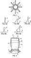
- Figure 1 shows a cover (1), the cover comprises a number of projecting elements (2) in the form of bristles, moulded at an acute angle with respect to the longitudinal axis of the cover to the outer surface (3) of the elongate tubular member.
- Figure 1 shows the projecting elements in their resting position and the tips pointing towards the proximal end (6).
- the projecting elements (2) are moulded at their base to form a raised portion or bump (4).
- a small air pocket is formed beneath the raised portion or bump (4) on the inner surface (7) of the cover which allows for flexibility of the projecting elements about their base in use and especially when negotiating the confines of a body passage.
- the projecting elements are angled, at rest in the so called first position, to around 45° to 65° towards the proximal end (6) of the cover and with respect to a central longitudinal axis of the cover and, in a forward or distal movement within a body passage once the endoscope or enteroscope has been inserted into the hollow (8) of the cover, the projecting elements are flattened so as to be approximately parallel to the said longitudinal axis with the projecting elements tips pointing towards the proximal end (6). This is the second position.
- the projecting elements are fanned out or expanded into a third position when the covered scope is withdrawn in a proximal movement.
- the endoscopist can apply the air suction means to withdraw air from the body passage causing the body passage wall to partially collapse about the projecting elements (2) and be drawn into the spaces (3) between the individual projecting elements and the spaces between rings and rows of rings of projecting elements.
- the wall of the body passage is gripped and wrapped around the cover, if further forward or distal movement is applied the body passage wall remains gripped by the projecting elements and effectively bunches up or concertinas in the proximal area thereby allowing the distal end to move forward and overcome the looping or bend obstacle.
- the projecting elements (2) are capable of flicking or flipping over past the critical point of maximum inflexion at 90° so that the tips point towards the distal end (5) in a so called fourth position, making withdrawal of the device through the relevant orifice more comfortable for the patient.
- they may be flattened against the cover main body as depicted in Figure 9B as described herein after.
- endoscopists have reported that the cover remains in position on the flexible medical scoping device shaft and that the projecting elements do not impede the periphery of the visual field.
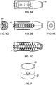
- the projecting elements may be in form of bristles ( Figure 8A ), fins or paddles ( Figure 8B ), cones ( Figure 8C ), bulbs, stalks or buds ( Figure 8D ) or any other flexible projection ( Figure 8E ).
- the projecting elements are provided in rings, typically of about 1 to 10 rings and more typically of two rings in uniform circumferential formation and evenly spaced apart with projecting elements being of a marginally shorter length in the first (distal end (5)) and last (proximal end (6)) rows.
- the cover is provided with several apertures (16) which are capable of fitting over rods provided on the applicator.
- Figure 2 shows a transverse section through the cover that has bristle type projecting elements.
- the distal end (5) of the cover is seen in greater detail.
- the distal end comprises a head (14) and a profiled end region (9, 10) over which a transparent cap (13) may be placed and held in position by clips (11, 12) or the like.
- This distal region is the end that is furthest in the patient and provides the light and lens through which the endoscopist can observe the body passage.
- the cap (13) is provided with the cover or may be placed in the applicator and the scope is inserted through the cover and caused to engage with the cap in situ.
- the end cap is an optional additional feature which can be provided if desired with either the cover or the applicator.
- FIG. 4 shows a disassembled applicator and the securing means (19) of the casings (17, 18) in the form of rods which are inserted into apertures (16) of the proximal end of the cover.
- an end cap can be held in place at the distal end.
- the casings are fitted together by any suitable means and the cover held in position within the shell or casing.
- Figure 6A shows a top view of an assembled casing and Figure 6B shows a side view with the cover in place inside, Figure 6C shows a top view of a disassembled applicator and cover, Figure 6D shows a proximal end view with the apertures of the cover over the rods stretching the cover to form an interior space 20 through which the scope is inserted and Figure 6E shows a distal end view with the viewing hole which may also include the end cap.
- a kit of parts which may optionally include a viewing means attachment (20) optionally provided with a portal (21) for removing under suction any excess fluid ( Figure 7 ).
- the projecting elements are not configured to adopt the fourth position where the tip ends are pointed in a distal direction following a flip over past the critical point at maximum inflexion.
- the cover is provided with a projecting element closure means (23) typically in the form of a sleeve ( Figures 9A and 9B ).
- the projecting elements closure means is pulled over the projecting elements by a cord or line or string (24) so that sleeve (23) unfurls in a proximal direction over the projecting elements (2) thereby flattening them against the scope shaft (E).
- a cord or line or string 244
- the cover is provided with slits or gaps (28) running in a longitudinal direction and between the distal (A) and proximal (B) regions of the cover, in this example the cover is also provided with an over cuff (25).
- the over cuff itself is also provided with slits or gaps (30) between its proximal and distal ends that are of approximately commensurate dimensions as the slits or gaps in the cover so that, when the over cuff is placed over the cover, the slits or gaps in both the cover and over cuff are aligned, providing continuous spaces (29) through both items whilst at each of the distal (A) and proximal (B) ends the cover and over-cuff have continuous rings (31 and 32).
- FIG. 10A shows a plan view of a cover and over cuff (25).
- the over cuff has a snug fit over the cover and is typically constructed of a polycarbonate or other plastics material, projecting elements (2) protrude outwardly between strips (26) of the over cuff and at the distal tip the over cuff it marginally overlaps the cover providing a rim (27) around hollow (8).
- the medical scoping device distal tip with the cover and over cuff (3, 25) is inserted via the anus (34) into the colon of an individual under investigation.
- the projecting elements are moved from an at rest position, referred herein before as the first position to a second position where they are flattened towards the medical scoping device shaft the so called second position ( Figure 12A ).
- the distal end tip of the medical scoping comprises a channel (37) through which a light source, image relaying mean and air suction is supplied.
- the projecting elements are designed to collapse into the device during insertion through the anus. This exposes the smooth low friction surface of the cover and over cuff to the mucosa to aid intubation.
- the flexible shaft (33) of the medical scoping device is advanced in a distal direction through the colon towards the bend or loop region (36) of the of the colon ( Figure 12B ) whilst insufflatting the colon immediately forwards of the distal tip.
- the projecting elements once passed the anus revert to their resting first position.
- the scope passes further up the colon and encounters the loop region the projecting elements engage with the colon wall in a soft grip (third position where the projecting elements fan out and the endoscopist can perform a controlled proximal withdrawal flattening the colonic folds for good visualisation ( Figure 12C ).
- the distal row of longer projecting elements is designed to open the colonic lumen for close inspection.
- the projecting elements of the cover of the present invention act to gently open and flatten the colonic folds for inspection during withdrawal, endoscopists report that the cover of the present invention provides distinct improvements. Improved visualisation is important for identifying small pre-malignant and malignant lesions that might be tucked out of sight when performing conventional endoscopy. Visualisation is further enhanced when using the cover, especially with wide vision endoscopes.
- the projecting elements of the device gently stabilise the tip of the scoping device within the lumen of the colon or small intestine immediately prior to and during therapeutic procedures.
- This has the advantage of permitting the endoscopist the reassurance that the tip will remain in position from the stage of visualising a lesion or polyp until completion of the therapeutic procedure.
- the distal row of the projecting elements are designed to flare outwards on withdrawal. They keep the instrument tip in the central part of the bowel lumen as the instrument moves backwards, gently holding the mucosa to prevent the tip from flipping backwards, they maintain position during therapy and improve all-round visualisation. During extubation they evert the folds enabling their proximal surface to be viewed.
- the endoscopist can apply air suction so that the colon wall (38) collapses onto the shaft (3) and into the spaces between adjacent rings of projecting elements (39), the projecting elements still being in the third position ( Figure 12D ).
- the colon wall concertinas about the shaft (3) and the endoscopist can then cease suction so that the colon wall straightens and the scope can be further advanced.
- the projecting elements can flip over to the fourth position so that the scope can be comfortably withdrawn.
- the cover is designed to provide controlled extubation.
- the colonoscope tip suddenly to slip backwards. This happens especially when passing a bend or flexure and the "missed" area then has to be re-intubated, sometimes with the creation of a painful loop.
- the long, soft, distal projecting elements prevent sudden tip slippage and hold the tip in the centre of the colonic lumen providing both control and good visualisation as the endoscope is withdrawn.
Claims (6)
- Recouvrement (1) pour un arbre de colonoscope (33), le recouvrement (1) comprenant un organe tubulaire allongé (3) et étant prévu pour être appliqué par-dessus l'arbre de colonoscope (33), le recouvrement (1) s'étendant le long d'au moins une partie de la longueur d'une extrémité distale de l'arbre, l'organe tubulaire (3) comprenant une surface intérieure (7), dont au moins une partie enserre l'arbre (33) et retient le recouvrement (1) en place, et une surface extérieure comprenant une pluralité d'éléments saillants espacés (2) ayant une pointe et une base, pouvant être déplacés entre :a) une position de repos et une position dans laquelle la pointe des éléments saillants (2) est sensiblement parallèle à un axe longitudinal du colonoscope etb) une position qui est orientée suivant un angle approximativement perpendiculaire à l'axe longitudinal de l'arbre de colonoscope (33) de telle sorte que lesdits éléments saillants (2) soient déployés en éventail de manière à entrer en contact avec, soutenir et dilater une paroi de lumière d'un passage corporel dans lequel a été inséré le colonoscope ;
les éléments saillants (2) étant agencés sous forme d'au moins un anneau s'étendant circonférentiellement autour du recouvrement (1), caractérisé en ce que les éléments saillants (2) se présentent sous la forme de poils ou de soies ayant un diamètre compris entre 0,5 et 3,0 mm et une longueur comprise entre 4 et 20 mm de la base à la pointe, et chaque anneau du recouvrement (1) comprenant entre 5 et 10 éléments saillants (2). - Recouvrement (1) selon la revendication 1, dans lequel les poils ou les soies présentent une longueur comprise entre 4 et 15 mm de la base à la pointe.
- Recouvrement (1) selon la revendication 2, dans lequel les poils ou les soies présentent une longueur comprise entre 4 et 10 mm de la base à la pointe.
- Recouvrement (1) selon l'une quelconque des revendications précédentes, dans lequel les éléments saillants (2) sont positionnés suivant un angle compris entre 35° et 85°, et facultativement entre 55 et 75° par rapport à l'axe longitudinal central du recouvrement (1).
- Recouvrement (1) selon l'une quelconque des revendications précédentes, dans lequel l'anneau le plus distal des éléments saillants (2) est positionné à une distance comprise entre 1 et 20 mm, et facultativement entre 5 et 15 mm, de l'extrémité distale du recouvrement (1).
- Colonoscope auquel est attaché un recouvrement (1) selon l'une quelconque des revendications précédentes.
Priority Applications (2)
| Application Number | Priority Date | Filing Date | Title |
|---|---|---|---|
| SI201131977T SI2937034T1 (sl) | 2010-05-25 | 2011-05-24 | Prevleka za medicinsko pregledovalno napravo |
| HRP20210797TT HRP20210797T1 (hr) | 2010-05-25 | 2021-05-18 | Pokrivalo za medicinski endoskopski uređaj |
Applications Claiming Priority (5)
| Application Number | Priority Date | Filing Date | Title |
|---|---|---|---|
| GBGB1008637.9A GB201008637D0 (en) | 2010-05-25 | 2010-05-25 | Covering for a medical scoping device |
| GBGB1101619.3A GB201101619D0 (en) | 2011-01-31 | 2011-01-31 | Covering for a medical scoping device |
| GBGB1107535.5A GB201107535D0 (en) | 2011-05-06 | 2011-05-06 | Covering for a medical scooping device |
| EP11722861.9A EP2575590B2 (fr) | 2010-05-25 | 2011-05-24 | Gaine pour dispositif de scopie médicale |
| PCT/GB2011/050981 WO2011148172A2 (fr) | 2010-05-25 | 2011-05-24 | Gaine pour dispositif de scopie médicale |
Related Parent Applications (2)
| Application Number | Title | Priority Date | Filing Date |
|---|---|---|---|
| EP11722861.9A Division EP2575590B2 (fr) | 2010-05-25 | 2011-05-24 | Gaine pour dispositif de scopie médicale |
| EP11722861.9A Division-Into EP2575590B2 (fr) | 2010-05-25 | 2011-05-24 | Gaine pour dispositif de scopie médicale |
Publications (2)
| Publication Number | Publication Date |
|---|---|
| EP2937034A1 EP2937034A1 (fr) | 2015-10-28 |
| EP2937034B1 true EP2937034B1 (fr) | 2021-03-24 |
Family
ID=44279541
Family Applications (2)
| Application Number | Title | Priority Date | Filing Date |
|---|---|---|---|
| EP15169674.7A Active EP2937034B1 (fr) | 2010-05-25 | 2011-05-24 | Revêtement pour un dispositif d'endoscopie médicale |
| EP11722861.9A Active EP2575590B2 (fr) | 2010-05-25 | 2011-05-24 | Gaine pour dispositif de scopie médicale |
Family Applications After (1)
| Application Number | Title | Priority Date | Filing Date |
|---|---|---|---|
| EP11722861.9A Active EP2575590B2 (fr) | 2010-05-25 | 2011-05-24 | Gaine pour dispositif de scopie médicale |
Country Status (27)
| Country | Link |
|---|---|
| US (4) | US9808142B2 (fr) |
| EP (2) | EP2937034B1 (fr) |
| JP (1) | JP5993370B2 (fr) |
| KR (1) | KR101849131B1 (fr) |
| CN (1) | CN102905608B (fr) |
| AU (1) | AU2011256957C1 (fr) |
| BR (1) | BR112012030053B1 (fr) |
| CA (1) | CA2800198C (fr) |
| CY (1) | CY1117192T1 (fr) |
| DE (1) | DE202011110721U1 (fr) |
| DK (1) | DK2575590T4 (fr) |
| ES (2) | ES2562264T5 (fr) |
| GB (1) | GB2478081B8 (fr) |
| HK (1) | HK1179139A1 (fr) |
| HR (2) | HRP20160090T4 (fr) |
| HU (1) | HUE026680T2 (fr) |
| MX (1) | MX2012013661A (fr) |
| MY (1) | MY184615A (fr) |
| PL (1) | PL2575590T5 (fr) |
| PT (1) | PT2575590E (fr) |
| RS (1) | RS54555B2 (fr) |
| RU (1) | RU2566918C2 (fr) |
| SG (1) | SG185636A1 (fr) |
| SI (2) | SI2937034T1 (fr) |
| SM (1) | SMT201600048B (fr) |
| WO (1) | WO2011148172A2 (fr) |
| ZA (1) | ZA201208828B (fr) |
Families Citing this family (61)
| Publication number | Priority date | Publication date | Assignee | Title |
|---|---|---|---|---|
| US8100822B2 (en) | 2004-03-16 | 2012-01-24 | Macroplata Systems, Llc | Anoscope for treating hemorrhoids without the trauma of cutting or the use of an endoscope |
| US10595711B2 (en) | 2009-12-16 | 2020-03-24 | Boston Scientific Scimed, Inc. | System for a minimally-invasive, operative gastrointestinal treatment |
| US10758116B2 (en) | 2009-12-16 | 2020-09-01 | Boston Scientific Scimed, Inc. | System for a minimally-invasive, operative gastrointestinal treatment |
| US8932211B2 (en) | 2012-06-22 | 2015-01-13 | Macroplata, Inc. | Floating, multi-lumen-catheter retractor system for a minimally-invasive, operative gastrointestinal treatment |
| US10966701B2 (en) | 2009-12-16 | 2021-04-06 | Boston Scientific Scimed, Inc. | Tissue retractor for minimally invasive surgery |
| USRE48850E1 (en) | 2009-12-16 | 2021-12-14 | Boston Scientific Scimed, Inc. | Multi-lumen-catheter retractor system for a minimally-invasive, operative gastrointestinal treatment |
| US9186131B2 (en) | 2009-12-16 | 2015-11-17 | Macroplata, Inc. | Multi-lumen-catheter retractor system for a minimally-invasive, operative gastrointestinal treatment |
| EP2512577B1 (fr) | 2009-12-16 | 2018-03-07 | Boston Scientific Scimed, Inc. | Dispositifs de réalisation d'une structure anatomique endo-luminale |
| US10531869B2 (en) | 2009-12-16 | 2020-01-14 | Boston Scientific Scimed, Inc. | Tissue retractor for minimally invasive surgery |
| US9565998B2 (en) | 2009-12-16 | 2017-02-14 | Boston Scientific Scimed, Inc. | Multi-lumen-catheter retractor system for a minimally-invasive, operative gastrointestinal treatment |
| CA2791838C (fr) | 2010-03-09 | 2019-03-05 | Smart Medical Systems Ltd | Endoscope a ballon, son procede de fabrication et sa methode d'utilisation |
| KR102440877B1 (ko) | 2011-02-16 | 2022-09-05 | 더 제너럴 하스피탈 코포레이션 | 내시경용 광 결합기 |
| AU2012226390B9 (en) | 2011-03-07 | 2017-02-02 | Smart Medical Systems Ltd | Balloon-equipped endoscopic devices and methods thereof |
| EP2895083B1 (fr) | 2012-09-14 | 2018-07-04 | Alpine Medical Devices, LLC | Ligateur |
| GB2507980B (en) * | 2012-11-15 | 2015-06-10 | Rolls Royce Plc | Inspection arrangement |
| EP2953518B1 (fr) * | 2013-02-07 | 2017-08-30 | Endoaid Ltd. | Gaine d'endoscope |
| US10299662B2 (en) * | 2013-02-07 | 2019-05-28 | Endoaid Ltd. | Endoscopic sleeve |
| JP6700172B2 (ja) | 2013-05-21 | 2020-05-27 | スマート・メディカル・システムズ・リミテッド | 内視鏡再処理方法 |
| US20140358089A1 (en) * | 2013-06-04 | 2014-12-04 | Boston Scientific Scimed, Inc. | Vacuum-assisted pancreaticobiliary cannulation |
| US10463235B2 (en) | 2014-02-24 | 2019-11-05 | Visualization Balloons, Llc | Gastrointestinal endoscopy with attachable intestine pleating structures |
| EP3131452A4 (fr) * | 2014-04-16 | 2018-01-03 | Visualization Balloons, LLC | Endoscopie gastro-intestinale avec dispositifs et procédés de plissage de l'intestin |
| US9459442B2 (en) | 2014-09-23 | 2016-10-04 | Scott Miller | Optical coupler for optical imaging visualization device |
| EP3236833B1 (fr) | 2014-11-24 | 2022-06-15 | Consis Medical Ltd. | Système, dispositif et procédé pour avancer un article le long d'un trajet |
| CN107105986B (zh) | 2014-12-22 | 2019-11-05 | 智能医疗系统有限公司 | 气囊内窥镜再处理系统和方法 |
| US10835107B2 (en) | 2015-04-03 | 2020-11-17 | Smart Medical Systems Ltd. | Endoscope electro-pneumatic adaptor |
| JP2018515255A (ja) | 2015-05-19 | 2018-06-14 | エンドエイド リミテッドEndoaid Ltd. | 羽根を備える内視鏡スリーブ |
| US10548467B2 (en) | 2015-06-02 | 2020-02-04 | GI Scientific, LLC | Conductive optical element |
| EP3313257A4 (fr) * | 2015-06-25 | 2019-01-30 | Medivators Inc. | Accessoire pour un dispositif d'endoscopie médicale |
| CA2992739A1 (fr) | 2015-07-21 | 2017-01-26 | GI Scientific, LLC | Accessoire d'endoscope avec portail de sortie a reglage angulaire |
| JP7082052B2 (ja) | 2015-09-03 | 2022-06-07 | ネプチューン メディカル インク. | 小腸内での内視鏡前進の為の器具 |
| CN108135446B (zh) * | 2015-10-23 | 2020-09-01 | Hoya株式会社 | 内窥镜末端附件装置 |
| GB201605358D0 (en) * | 2016-03-30 | 2016-05-11 | Meditech Endoscopy Ltd | Instrument tip protector |
| GB201608380D0 (en) | 2016-05-12 | 2016-06-29 | Arc Medical Design Ltd | Medical scope accessory, medical scopes comprising the accessory, and use thereof |
| US10980975B2 (en) | 2016-05-19 | 2021-04-20 | Ibex Technologies Ltd. | System, device and method for advancing an article along a path |
| CN109414154B (zh) * | 2016-07-01 | 2022-09-20 | 波士顿科学国际有限公司 | 用于输送医疗工具的装置和方法 |
| EP3500151A4 (fr) | 2016-08-18 | 2020-03-25 | Neptune Medical Inc. | Dispositif et procédé de visualisation améliorée de l'intestin grêle |
| US10709313B2 (en) | 2016-09-21 | 2020-07-14 | NCI, Inc. | Surgical instrument inspection system |
| CN106343941B (zh) * | 2016-11-03 | 2017-09-05 | 沈阳尚贤医疗系统有限公司 | 内窥镜套筒 |
| IT201600124851A1 (it) * | 2016-12-12 | 2018-06-12 | Alessandro Budano | Dispositivo per endoscopia |
| US11071534B2 (en) | 2016-12-30 | 2021-07-27 | Boston Scientific Scimed, Inc. | System for a minimally-invasive treatment within a body lumen |
| CN116327271A (zh) | 2017-03-18 | 2023-06-27 | 波士顿科学国际有限公司 | 用于体腔内的微创治疗的系统 |
| DE102017106846A1 (de) * | 2017-03-30 | 2018-10-04 | Aesculap Ag | Chirurgisches Retraktorsystem mit einem Retraktor und einem Extraktor sowie ein torsionsbeaufschlagendes chirurgisches Instrument |
| EP3613330B1 (fr) * | 2017-04-19 | 2024-02-28 | Hoya Corporation | Dispositif de fixation pour partie d'extrémité d'endoscope |
| USD870280S1 (en) | 2017-05-26 | 2019-12-17 | Medivators Inc. | Fitting for an endoscope device having protuberances |
| USD870281S1 (en) | 2017-05-26 | 2019-12-17 | Medivators Inc. | Fitting for an endoscope device having a tab |
| WO2019104329A1 (fr) * | 2017-11-27 | 2019-05-31 | Optecks, Llc | Système médical tridimensionnel (3d) de balayage et de cartographie |
| CN107928606B (zh) * | 2017-12-11 | 2019-04-19 | 荣佳(惠州)医疗器械制造有限公司 | 一种医疗内窥镜套筒 |
| CN108261174A (zh) * | 2018-03-13 | 2018-07-10 | 南京微创医学科技股份有限公司 | 一种内窥镜端帽 |
| EP3823711A4 (fr) | 2018-07-19 | 2022-05-18 | Neptune Medical Inc. | Structures médicales composites à rigidification dynamique |
| RU188717U1 (ru) * | 2018-10-26 | 2019-04-22 | Общество с ограниченной ответственностью "НПФ "ЭлМед" | Устройство для нейрохирургического эндоскопического вмешательства |
| WO2020138537A1 (fr) * | 2018-12-27 | 2020-07-02 | 경상대학교병원 | Unité d'aspiration médicale |
| US11013530B2 (en) * | 2019-03-08 | 2021-05-25 | Medos International Sarl | Surface features for device retention |
| US11793392B2 (en) | 2019-04-17 | 2023-10-24 | Neptune Medical Inc. | External working channels |
| US11832789B2 (en) | 2019-12-13 | 2023-12-05 | Boston Scientific Scimed, Inc. | Devices, systems, and methods for minimally invasive surgery in a body lumen |
| JP2023522561A (ja) * | 2020-03-05 | 2023-05-31 | アレクサンダー ヒュルゼン, | 内視鏡フード |
| US11744443B2 (en) | 2020-03-30 | 2023-09-05 | Neptune Medical Inc. | Layered walls for rigidizing devices |
| CN114828728A (zh) * | 2021-02-10 | 2022-07-29 | 株式会社名优 | 摄影机防护袋 |
| US20220395171A1 (en) * | 2021-06-15 | 2022-12-15 | Arthrex, Inc. | Surgical camera system |
| KR20230017639A (ko) * | 2021-07-28 | 2023-02-06 | 고지환 | 내시경 캡 |
| WO2023122767A2 (fr) * | 2021-12-22 | 2023-06-29 | Neptune Medical Inc. | Procédés et appareils pour réduire la courbure d'un côlon |
| US20230346204A1 (en) | 2022-04-27 | 2023-11-02 | Neptune Medical Inc. | Endoscope sheath apparatuses |
Citations (3)
| Publication number | Priority date | Publication date | Assignee | Title |
|---|---|---|---|---|
| JP2003033319A (ja) * | 2001-07-19 | 2003-02-04 | Olympus Optical Co Ltd | 内視鏡挿入補助具 |
| JP2003180611A (ja) * | 2001-12-18 | 2003-07-02 | Olympus Optical Co Ltd | 内視鏡挿入補助具 |
| JP2003339631A (ja) * | 2002-05-23 | 2003-12-02 | Olympus Optical Co Ltd | 内視鏡挿入補助具 |
Family Cites Families (81)
| Publication number | Priority date | Publication date | Assignee | Title |
|---|---|---|---|---|
| FR1278965A (fr) * | 1961-01-27 | 1961-12-15 | Maison Drapier | Perfectionnements aux cathéters médicaux |
| US3717151A (en) | 1971-03-11 | 1973-02-20 | R Collett | Flesh penetrating apparatus |
| US4207872A (en) * | 1977-12-16 | 1980-06-17 | Northwestern University | Device and method for advancing an endoscope through a body passage |
| US5018509A (en) * | 1989-02-21 | 1991-05-28 | Olympus Optical Co., Ltd. | Endoscope insertion controlling apparatus |
| JPH0777576B2 (ja) * | 1991-03-27 | 1995-08-23 | 了司 服部 | 内視鏡の付属品及び内視鏡 |
| DE4137303C2 (de) * | 1991-11-13 | 1993-12-02 | Rheintechnik Weiland & Kaspar | Verfahren zur Messung der elektrischen Leitfähigkeit von Körperflüssigkeiten, sowie hierbei verwandte Meßsonde |
| US5259366A (en) * | 1992-11-03 | 1993-11-09 | Boris Reydel | Method of using a catheter-sleeve assembly for an endoscope |
| US5653690A (en) * | 1992-12-30 | 1997-08-05 | Medtronic, Inc. | Catheter having a balloon with retention enhancement |
| JP2855246B2 (ja) * | 1993-09-08 | 1999-02-10 | 日野自動車工業株式会社 | ミリ波送受信装置、ミリ波受信装置、およびミリ波送受信用アンテナ |
| US5505686A (en) | 1994-05-05 | 1996-04-09 | Imagyn Medical, Inc. | Endoscope with protruding member and method of utilizing the same |
| JP3178321B2 (ja) | 1995-11-24 | 2001-06-18 | 富士写真光機株式会社 | 体腔内挿入部材の軟質部保護具 |
| US5817062A (en) | 1996-03-12 | 1998-10-06 | Heartport, Inc. | Trocar |
| GB9610765D0 (en) | 1996-05-23 | 1996-07-31 | Axon Anthony T R | Improvements in or relating to endoscopes |
| WO1998047422A2 (fr) | 1997-04-21 | 1998-10-29 | Barry David Brighton | Appareil endoscopique |
| US6589213B2 (en) | 1997-12-12 | 2003-07-08 | Wilson-Cook Medical Incorporated | Body canal intrusion instrumentation having bi-directional coefficient of surface friction with body tissue |
| US6406425B1 (en) | 1998-06-22 | 2002-06-18 | Origin Medasystems | Cannula-based irrigation system and method |
| US5916145A (en) | 1998-08-07 | 1999-06-29 | Scimed Life Systems, Inc. | Device and method of using a surgical assembly with mesh sheath |
| EP1109590A1 (fr) | 1998-09-03 | 2001-06-27 | H.D.S. Systems, Ltd. | Catheters a ecoulement dirige munis d'un bout a ailettes |
| JP2002534200A (ja) | 1999-01-19 | 2002-10-15 | タイコ ヘルスケア グループ リミテッド パートナーシップ | 外科手術器具のための鞘部材およびアプリケータ |
| DE10027447A1 (de) | 1999-07-22 | 2001-02-01 | Univ Ilmenau Tech | Fluidischer, peristaltischer Antrieb |
| US6858005B2 (en) | 2000-04-03 | 2005-02-22 | Neo Guide Systems, Inc. | Tendon-driven endoscope and methods of insertion |
| US6988986B2 (en) | 2002-11-25 | 2006-01-24 | G. I. View | Self-propelled imaging system |
| WO2003005877A2 (fr) | 2001-07-12 | 2003-01-23 | Given Imaging Ltd. | Dispositif et procede d'examen d'une lumiere corporelle |
| US6913610B2 (en) | 2001-10-16 | 2005-07-05 | Granit Medical Innovations, Inc. | Endoscopic retractor instrument and associated method |
| KR100417163B1 (ko) | 2001-11-12 | 2004-02-05 | 한국과학기술연구원 | 마이크로 캡슐형 로봇 |
| JP3826045B2 (ja) | 2002-02-07 | 2006-09-27 | オリンパス株式会社 | 内視鏡用フード |
| ES1051891Y (es) | 2002-04-25 | 2003-02-16 | Francisco Hernandez Altemir S | Tubo nasotraqueal para exploracion e intubacion. |
| EP1513440A2 (fr) | 2002-05-30 | 2005-03-16 | The Board of Trustees of The Leland Stanford Junior University | Appareil et procede pour acceder au sinus coronaire |
| US6790173B2 (en) | 2002-06-13 | 2004-09-14 | Usgi Medical, Inc. | Shape lockable apparatus and method for advancing an instrument through unsupported anatomy |
| US6679836B2 (en) * | 2002-06-21 | 2004-01-20 | Scimed Life Systems, Inc. | Universal programmable guide catheter |
| JP3791916B2 (ja) | 2002-10-11 | 2006-06-28 | オリンパス株式会社 | 内視鏡用先端フード部材 |
| US6958035B2 (en) | 2002-10-15 | 2005-10-25 | Dusa Pharmaceuticals, Inc | Medical device sheath apparatus and method of making and using same |
| US7122003B2 (en) | 2003-04-16 | 2006-10-17 | Granit Medical Innovations, Llc | Endoscopic retractor instrument and associated method |
| US7473220B2 (en) | 2003-08-04 | 2009-01-06 | Medcanica, Inc. | Surgical port device |
| ITMI20032278A1 (it) | 2003-11-21 | 2005-05-22 | Ethicon Endo Surgery Inc | Dispositivo di diagnosi |
| US7195592B2 (en) | 2004-01-27 | 2007-03-27 | Sundaram Ravikumar | Surgical retractor apparatus for use with a surgical port |
| JP3877075B2 (ja) | 2004-01-28 | 2007-02-07 | 有限会社エスアールジェイ | 内視鏡装置 |
| JP2006026344A (ja) | 2004-07-12 | 2006-02-02 | Toshifumi Hayakawa | 大腸内視鏡挿入用伸展脚式移動シース |
| US20060025653A1 (en) | 2004-07-28 | 2006-02-02 | Phonak Ag | Structure for probe insertion |
| JP4648712B2 (ja) * | 2005-01-14 | 2011-03-09 | Hoya株式会社 | 大腸挿入用内視鏡の先端部 |
| US20060258909A1 (en) | 2005-04-08 | 2006-11-16 | Usgi Medical, Inc. | Methods and apparatus for maintaining sterility during transluminal procedures |
| US20060287666A1 (en) | 2005-06-15 | 2006-12-21 | Usgi Medical Inc. | Apparatus and methods for endoluminal advancement |
| US20070015965A1 (en) * | 2005-07-13 | 2007-01-18 | Usgi Medical Inc. | Methods and apparatus for colonic cleaning |
| EP1772104A2 (fr) | 2005-10-07 | 2007-04-11 | Tsion Israel Medical Systems Ltd. | Dispositif de protection anti-contamination |
| JP4804864B2 (ja) | 2005-10-07 | 2011-11-02 | 日立オムロンターミナルソリューションズ株式会社 | 紙幣取扱システム |
| US20070149850A1 (en) | 2005-12-22 | 2007-06-28 | Spivey James T | Endoscope endcap attachment tool |
| US8092371B2 (en) | 2006-01-13 | 2012-01-10 | Olympus Medical Systems Corp. | Medical treatment endoscope |
| EP1983882A2 (fr) | 2006-01-30 | 2008-10-29 | Vision Sciences Inc. | Endoscope controlable |
| US8016794B2 (en) | 2006-03-09 | 2011-09-13 | Interrad Medical, Inc. | Anchor device and method |
| US8915842B2 (en) | 2008-07-14 | 2014-12-23 | Ethicon Endo-Surgery, Inc. | Methods and devices for maintaining visibility and providing irrigation and/or suction during surgical procedures |
| US8348889B2 (en) * | 2006-06-01 | 2013-01-08 | Arash Salemi | Self-retaining and fluid delivery catheter |
| JP4885640B2 (ja) * | 2006-08-01 | 2012-02-29 | オリンパスメディカルシステムズ株式会社 | 内視鏡用挿入補助具 |
| WO2008028022A2 (fr) | 2006-09-01 | 2008-03-06 | Nidus Medical, Llc | Dispositif de visualisation de tissu à un cadre à plusieurs segments |
| EP2061547A2 (fr) | 2006-09-11 | 2009-05-27 | Pluromed, Inc. | Ballonnets et jupes d'occlusion atraumatiques et leurs méthodes d'utilisation |
| US8025656B2 (en) | 2006-11-07 | 2011-09-27 | Hologic, Inc. | Methods, systems and devices for performing gynecological procedures |
| US20090306472A1 (en) | 2007-01-18 | 2009-12-10 | Filipi Charles J | Systems and techniques for endoscopic dilation |
| GB0706783D0 (en) | 2007-04-05 | 2007-05-16 | Systems Medical Ltd | Apparatus for deploying endoscope |
| WO2009011881A1 (fr) | 2007-07-18 | 2009-01-22 | Barosense, Inc. | Introducteur d'enveloppe de tube pour utilisation en chirurgie bariatrique endoscopique |
| JP2009045141A (ja) * | 2007-08-16 | 2009-03-05 | Fujifilm Corp | 内視鏡用挿入補助具及び内視鏡 |
| JP5284628B2 (ja) | 2007-11-28 | 2013-09-11 | オリンパスメディカルシステムズ株式会社 | 内視鏡用処置システム |
| WO2009076176A1 (fr) | 2007-12-07 | 2009-06-18 | Edward Diao | Système endoscopique pour accéder à des espaces chirurgicaux contraints |
| US20090281374A1 (en) | 2008-01-11 | 2009-11-12 | Leanna Gary | Endoscope Anchoring Device |
| US20090287052A1 (en) | 2008-05-19 | 2009-11-19 | Boston Scientific Scimed, Inc. | Biopsy Cap Attachment and Integrated Locking Device |
| US8337394B2 (en) | 2008-10-01 | 2012-12-25 | Ethicon Endo-Surgery, Inc. | Overtube with expandable tip |
| CN102123652B (zh) | 2009-02-18 | 2013-09-11 | 奥林巴斯医疗株式会社 | 内窥镜插入装置 |
| US8568308B2 (en) | 2009-08-14 | 2013-10-29 | Alan M. Reznik | Customizable, self holding, space retracting arthroscopic/endoscopic cannula system |
| US20120197083A1 (en) | 2009-10-01 | 2012-08-02 | Gi Motions Ltd. | Method and apparatus for endoscope advancement |
| ES2341086B2 (es) | 2010-01-29 | 2011-01-03 | Nicolas Anthony Costovici | Cateter para la practica de colonoscopia por imagen. |
| CA2799188A1 (fr) | 2010-05-11 | 2011-11-17 | Cook Medical Technologies Llc | Gaine d'acces biliaire |
| WO2012137364A1 (fr) | 2011-04-08 | 2012-10-11 | オリンパスメディカルシステムズ株式会社 | Endoscope |
| FR2977135B1 (fr) | 2011-06-29 | 2014-10-10 | Univ Paris Curie | Instrument endoscopique a pied d'appui |
| WO2013134600A1 (fr) | 2012-03-08 | 2013-09-12 | The Cleveland Clinic Foundation | Dispositifs, systèmes et procédés pour visualiser et manipuler des tissus |
| JP5975257B2 (ja) | 2012-03-08 | 2016-08-23 | 国立大学法人 香川大学 | 領域確保用器具および領域確保用器具を備えた内視鏡 |
| US9095299B2 (en) | 2012-04-23 | 2015-08-04 | Stephen P. RAY | Surgical sleeve suction retractor |
| WO2013190543A1 (fr) | 2012-06-17 | 2013-12-27 | Gi Motions, Ltd. | Procédé et appareil pour avancement de dispositif à l'intérieur d'une lumière |
| CN104394752B (zh) | 2012-09-19 | 2016-08-24 | 奥林巴斯株式会社 | 插拔辅助器械 |
| US9717399B2 (en) | 2012-09-28 | 2017-08-01 | Endopodium, Inc. | Endoscope with multifunctional extendible arms and endoscopic instrument with integrated image capture for use therewith |
| EP2767214B1 (fr) | 2012-10-10 | 2017-07-19 | Olympus Corporation | Instrument de traitement |
| CN104837395B (zh) | 2012-11-05 | 2018-04-03 | 奥林巴斯株式会社 | 插拔辅助器具以及具有该插拔辅助器具的内窥镜 |
| EP2953518B1 (fr) | 2013-02-07 | 2017-08-30 | Endoaid Ltd. | Gaine d'endoscope |
| JP2014212835A (ja) | 2013-04-23 | 2014-11-17 | ショーダテクトロン株式会社 | 内視鏡用フードおよび同内視鏡用フードを備えた内視鏡 |
-
2011
- 2011-05-24 EP EP15169674.7A patent/EP2937034B1/fr active Active
- 2011-05-24 SI SI201131977T patent/SI2937034T1/sl unknown
- 2011-05-24 HU HUE11722861A patent/HUE026680T2/en unknown
- 2011-05-24 WO PCT/GB2011/050981 patent/WO2011148172A2/fr active Application Filing
- 2011-05-24 CA CA2800198A patent/CA2800198C/fr active Active
- 2011-05-24 SG SG2012084729A patent/SG185636A1/en unknown
- 2011-05-24 RS RS20160068A patent/RS54555B2/sr unknown
- 2011-05-24 EP EP11722861.9A patent/EP2575590B2/fr active Active
- 2011-05-24 AU AU2011256957A patent/AU2011256957C1/en active Active
- 2011-05-24 DE DE202011110721.7U patent/DE202011110721U1/de not_active Expired - Lifetime
- 2011-05-24 PT PT117228619T patent/PT2575590E/pt unknown
- 2011-05-24 ES ES11722861T patent/ES2562264T5/es active Active
- 2011-05-24 RU RU2012150742/14A patent/RU2566918C2/ru active
- 2011-05-24 GB GB201108723A patent/GB2478081B8/en active Active
- 2011-05-24 MY MYPI2012005000A patent/MY184615A/en unknown
- 2011-05-24 DK DK11722861.9T patent/DK2575590T4/en active
- 2011-05-24 US US13/699,172 patent/US9808142B2/en active Active
- 2011-05-24 KR KR1020127030902A patent/KR101849131B1/ko active IP Right Grant
- 2011-05-24 MX MX2012013661A patent/MX2012013661A/es unknown
- 2011-05-24 BR BR112012030053-9A patent/BR112012030053B1/pt active IP Right Grant
- 2011-05-24 SI SI201130733T patent/SI2575590T2/sl unknown
- 2011-05-24 ES ES15169674T patent/ES2873206T3/es active Active
- 2011-05-24 CN CN201180026078.5A patent/CN102905608B/zh active Active
- 2011-05-24 JP JP2013511740A patent/JP5993370B2/ja active Active
- 2011-05-24 PL PL11722861T patent/PL2575590T5/pl unknown
-
2012
- 2012-11-22 ZA ZA2012/08828A patent/ZA201208828B/en unknown
-
2013
- 2013-05-23 HK HK13106112.5A patent/HK1179139A1/zh active IP Right Maintenance
-
2016
- 2016-01-27 HR HRP20160090TT patent/HRP20160090T4/hr unknown
- 2016-02-12 CY CY20161100117T patent/CY1117192T1/el unknown
- 2016-02-16 SM SM201600048T patent/SMT201600048B/xx unknown
-
2017
- 2017-09-15 US US15/705,390 patent/US10722103B2/en active Active
-
2020
- 2020-06-18 US US16/904,776 patent/US11382494B2/en active Active
-
2021
- 2021-05-18 HR HRP20210797TT patent/HRP20210797T1/hr unknown
-
2022
- 2022-05-19 US US17/748,176 patent/US20220346634A1/en active Pending
Patent Citations (3)
| Publication number | Priority date | Publication date | Assignee | Title |
|---|---|---|---|---|
| JP2003033319A (ja) * | 2001-07-19 | 2003-02-04 | Olympus Optical Co Ltd | 内視鏡挿入補助具 |
| JP2003180611A (ja) * | 2001-12-18 | 2003-07-02 | Olympus Optical Co Ltd | 内視鏡挿入補助具 |
| JP2003339631A (ja) * | 2002-05-23 | 2003-12-02 | Olympus Optical Co Ltd | 内視鏡挿入補助具 |
Also Published As
Similar Documents
| Publication | Publication Date | Title |
|---|---|---|
| US11382494B2 (en) | Covering for a medical scoping device | |
| EP2953518B1 (fr) | Gaine d'endoscope | |
| US10299662B2 (en) | Endoscopic sleeve | |
| US20180153380A1 (en) | Endoscopic sleeve with wings | |
| AU2018100900A4 (en) | Covering for a medical scoping device | |
| AU2013263814B2 (en) | Covering for a medical scoping device |
Legal Events
| Date | Code | Title | Description |
|---|---|---|---|
| PUAI | Public reference made under article 153(3) epc to a published international application that has entered the european phase |
Free format text: ORIGINAL CODE: 0009012 |
|
| AC | Divisional application: reference to earlier application |
Ref document number: 2575590 Country of ref document: EP Kind code of ref document: P |
|
| AK | Designated contracting states |
Kind code of ref document: A1 Designated state(s): AL AT BE BG CH CY CZ DE DK EE ES FI FR GB GR HR HU IE IS IT LI LT LU LV MC MK MT NL NO PL PT RO RS SE SI SK SM TR |
|
| 17P | Request for examination filed |
Effective date: 20160321 |
|
| RBV | Designated contracting states (corrected) |
Designated state(s): AL AT BE BG CH CY CZ DE DK EE ES FI FR GB GR HR HU IE IS IT LI LT LU LV MC MK MT NL NO PL PT RO RS SE SI SK SM TR |
|
| STAA | Information on the status of an ep patent application or granted ep patent |
Free format text: STATUS: EXAMINATION IS IN PROGRESS |
|
| 17Q | First examination report despatched |
Effective date: 20180724 |
|
| GRAP | Despatch of communication of intention to grant a patent |
Free format text: ORIGINAL CODE: EPIDOSNIGR1 |
|
| STAA | Information on the status of an ep patent application or granted ep patent |
Free format text: STATUS: GRANT OF PATENT IS INTENDED |
|
| INTG | Intention to grant announced |
Effective date: 20200603 |
|
| GRAJ | Information related to disapproval of communication of intention to grant by the applicant or resumption of examination proceedings by the epo deleted |
Free format text: ORIGINAL CODE: EPIDOSDIGR1 |
|
| STAA | Information on the status of an ep patent application or granted ep patent |
Free format text: STATUS: EXAMINATION IS IN PROGRESS |
|
| GRAP | Despatch of communication of intention to grant a patent |
Free format text: ORIGINAL CODE: EPIDOSNIGR1 |
|
| STAA | Information on the status of an ep patent application or granted ep patent |
Free format text: STATUS: GRANT OF PATENT IS INTENDED |
|
| INTC | Intention to grant announced (deleted) | ||
| INTG | Intention to grant announced |
Effective date: 20200827 |
|
| GRAS | Grant fee paid |
Free format text: ORIGINAL CODE: EPIDOSNIGR3 |
|
| STAA | Information on the status of an ep patent application or granted ep patent |
Free format text: STATUS: GRANT OF PATENT IS INTENDED |
|
| GRAA | (expected) grant |
Free format text: ORIGINAL CODE: 0009210 |
|
| STAA | Information on the status of an ep patent application or granted ep patent |
Free format text: STATUS: THE PATENT HAS BEEN GRANTED |
|
| AC | Divisional application: reference to earlier application |
Ref document number: 2575590 Country of ref document: EP Kind code of ref document: P |
|
| AK | Designated contracting states |
Kind code of ref document: B1 Designated state(s): AL AT BE BG CH CY CZ DE DK EE ES FI FR GB GR HR HU IE IS IT LI LT LU LV MC MK MT NL NO PL PT RO RS SE SI SK SM TR |
|
| REG | Reference to a national code |
Ref country code: GB Ref legal event code: FG4D |
|
| REG | Reference to a national code |
Ref country code: CH Ref legal event code: EP |
|
| REG | Reference to a national code |
Ref country code: IE Ref legal event code: FG4D |
|
| REG | Reference to a national code |
Ref country code: AT Ref legal event code: REF Ref document number: 1373620 Country of ref document: AT Kind code of ref document: T Effective date: 20210415 Ref country code: DE Ref legal event code: R096 Ref document number: 602011070508 Country of ref document: DE |
|
| REG | Reference to a national code |
Ref country code: HR Ref legal event code: TUEP Ref document number: P20210797T Country of ref document: HR |
|
| REG | Reference to a national code |
Ref country code: FI Ref legal event code: FGE |
|
| REG | Reference to a national code |
Ref country code: SE Ref legal event code: TRGR |
|
| REG | Reference to a national code |
Ref country code: NL Ref legal event code: FP |
|
| REG | Reference to a national code |
Ref country code: LT Ref legal event code: MG9D |
|
| PG25 | Lapsed in a contracting state [announced via postgrant information from national office to epo] |
Ref country code: GR Free format text: LAPSE BECAUSE OF FAILURE TO SUBMIT A TRANSLATION OF THE DESCRIPTION OR TO PAY THE FEE WITHIN THE PRESCRIBED TIME-LIMIT Effective date: 20210625 Ref country code: NO Free format text: LAPSE BECAUSE OF FAILURE TO SUBMIT A TRANSLATION OF THE DESCRIPTION OR TO PAY THE FEE WITHIN THE PRESCRIBED TIME-LIMIT Effective date: 20210624 Ref country code: BG Free format text: LAPSE BECAUSE OF FAILURE TO SUBMIT A TRANSLATION OF THE DESCRIPTION OR TO PAY THE FEE WITHIN THE PRESCRIBED TIME-LIMIT Effective date: 20210624 |
|
| REG | Reference to a national code |
Ref country code: HR Ref legal event code: T1PR Ref document number: P20210797 Country of ref document: HR |
|
| PG25 | Lapsed in a contracting state [announced via postgrant information from national office to epo] |
Ref country code: RS Free format text: LAPSE BECAUSE OF FAILURE TO SUBMIT A TRANSLATION OF THE DESCRIPTION OR TO PAY THE FEE WITHIN THE PRESCRIBED TIME-LIMIT Effective date: 20210324 Ref country code: LV Free format text: LAPSE BECAUSE OF FAILURE TO SUBMIT A TRANSLATION OF THE DESCRIPTION OR TO PAY THE FEE WITHIN THE PRESCRIBED TIME-LIMIT Effective date: 20210324 |
|
| REG | Reference to a national code |
Ref country code: AT Ref legal event code: MK05 Ref document number: 1373620 Country of ref document: AT Kind code of ref document: T Effective date: 20210324 |
|
| REG | Reference to a national code |
Ref country code: HR Ref legal event code: ODRP Ref document number: P20210797 Country of ref document: HR Payment date: 20210824 Year of fee payment: 11 |
|
| PG25 | Lapsed in a contracting state [announced via postgrant information from national office to epo] |
Ref country code: SM Free format text: LAPSE BECAUSE OF FAILURE TO SUBMIT A TRANSLATION OF THE DESCRIPTION OR TO PAY THE FEE WITHIN THE PRESCRIBED TIME-LIMIT Effective date: 20210324 Ref country code: EE Free format text: LAPSE BECAUSE OF FAILURE TO SUBMIT A TRANSLATION OF THE DESCRIPTION OR TO PAY THE FEE WITHIN THE PRESCRIBED TIME-LIMIT Effective date: 20210324 Ref country code: CZ Free format text: LAPSE BECAUSE OF FAILURE TO SUBMIT A TRANSLATION OF THE DESCRIPTION OR TO PAY THE FEE WITHIN THE PRESCRIBED TIME-LIMIT Effective date: 20210324 Ref country code: LT Free format text: LAPSE BECAUSE OF FAILURE TO SUBMIT A TRANSLATION OF THE DESCRIPTION OR TO PAY THE FEE WITHIN THE PRESCRIBED TIME-LIMIT Effective date: 20210324 Ref country code: AT Free format text: LAPSE BECAUSE OF FAILURE TO SUBMIT A TRANSLATION OF THE DESCRIPTION OR TO PAY THE FEE WITHIN THE PRESCRIBED TIME-LIMIT Effective date: 20210324 |
|
| REG | Reference to a national code |
Ref country code: ES Ref legal event code: FG2A Ref document number: 2873206 Country of ref document: ES Kind code of ref document: T3 Effective date: 20211103 |
|
| PG25 | Lapsed in a contracting state [announced via postgrant information from national office to epo] |
Ref country code: IS Free format text: LAPSE BECAUSE OF FAILURE TO SUBMIT A TRANSLATION OF THE DESCRIPTION OR TO PAY THE FEE WITHIN THE PRESCRIBED TIME-LIMIT Effective date: 20210724 Ref country code: PL Free format text: LAPSE BECAUSE OF FAILURE TO SUBMIT A TRANSLATION OF THE DESCRIPTION OR TO PAY THE FEE WITHIN THE PRESCRIBED TIME-LIMIT Effective date: 20210324 Ref country code: PT Free format text: LAPSE BECAUSE OF FAILURE TO SUBMIT A TRANSLATION OF THE DESCRIPTION OR TO PAY THE FEE WITHIN THE PRESCRIBED TIME-LIMIT Effective date: 20210726 Ref country code: SK Free format text: LAPSE BECAUSE OF FAILURE TO SUBMIT A TRANSLATION OF THE DESCRIPTION OR TO PAY THE FEE WITHIN THE PRESCRIBED TIME-LIMIT Effective date: 20210324 Ref country code: RO Free format text: LAPSE BECAUSE OF FAILURE TO SUBMIT A TRANSLATION OF THE DESCRIPTION OR TO PAY THE FEE WITHIN THE PRESCRIBED TIME-LIMIT Effective date: 20210324 |
|
| REG | Reference to a national code |
Ref country code: CH Ref legal event code: PL |
|
| REG | Reference to a national code |
Ref country code: DE Ref legal event code: R097 Ref document number: 602011070508 Country of ref document: DE |
|
| REG | Reference to a national code |
Ref country code: DE Ref legal event code: R081 Ref document number: 602011070508 Country of ref document: DE Owner name: KEYMED ( MEDICAL & INDUSTRIAL EQUIPMENT) LIMIT, GB Free format text: FORMER OWNER: ARC MEDICAL DESIGN LIMITED, LEEDS, YORKSHIRE, GB Ref country code: DE Ref legal event code: R081 Ref document number: 602011070508 Country of ref document: DE Owner name: KEYMED (MEDICAL & INDUSTRIAL EQUIPMENT) LTD., , GB Free format text: FORMER OWNER: ARC MEDICAL DESIGN LIMITED, LEEDS, YORKSHIRE, GB |
|
| RAP2 | Party data changed (patent owner data changed or rights of a patent transferred) |
Owner name: KEYMED (MEDICAL & INDUSTRIAL EQUIPMENT) LIMITED |
|
| PG25 | Lapsed in a contracting state [announced via postgrant information from national office to epo] |
Ref country code: DK Free format text: LAPSE BECAUSE OF FAILURE TO SUBMIT A TRANSLATION OF THE DESCRIPTION OR TO PAY THE FEE WITHIN THE PRESCRIBED TIME-LIMIT Effective date: 20210324 Ref country code: CH Free format text: LAPSE BECAUSE OF NON-PAYMENT OF DUE FEES Effective date: 20210531 Ref country code: AL Free format text: LAPSE BECAUSE OF FAILURE TO SUBMIT A TRANSLATION OF THE DESCRIPTION OR TO PAY THE FEE WITHIN THE PRESCRIBED TIME-LIMIT Effective date: 20210324 Ref country code: MC Free format text: LAPSE BECAUSE OF FAILURE TO SUBMIT A TRANSLATION OF THE DESCRIPTION OR TO PAY THE FEE WITHIN THE PRESCRIBED TIME-LIMIT Effective date: 20210324 Ref country code: LU Free format text: LAPSE BECAUSE OF NON-PAYMENT OF DUE FEES Effective date: 20210524 Ref country code: LI Free format text: LAPSE BECAUSE OF NON-PAYMENT OF DUE FEES Effective date: 20210531 |
|
| REG | Reference to a national code |
Ref country code: GB Ref legal event code: 732E Free format text: REGISTERED BETWEEN 20220106 AND 20220112 |
|
| PLBE | No opposition filed within time limit |
Free format text: ORIGINAL CODE: 0009261 |
|
| STAA | Information on the status of an ep patent application or granted ep patent |
Free format text: STATUS: NO OPPOSITION FILED WITHIN TIME LIMIT |
|
| REG | Reference to a national code |
Ref country code: BE Ref legal event code: MM Effective date: 20210531 |
|
| 26N | No opposition filed |
Effective date: 20220104 |
|
| PG25 | Lapsed in a contracting state [announced via postgrant information from national office to epo] |
Ref country code: IS Free format text: LAPSE BECAUSE OF FAILURE TO SUBMIT A TRANSLATION OF THE DESCRIPTION OR TO PAY THE FEE WITHIN THE PRESCRIBED TIME-LIMIT Effective date: 20210724 |
|
| REG | Reference to a national code |
Ref country code: HR Ref legal event code: ODRP Ref document number: P20210797 Country of ref document: HR Payment date: 20220519 Year of fee payment: 12 |
|
| REG | Reference to a national code |
Ref country code: DE Ref legal event code: R081 Ref document number: 602011070508 Country of ref document: DE Owner name: KEYMED ( MEDICAL & INDUSTRIAL EQUIPMENT) LIMIT, GB Free format text: FORMER OWNER: KEYMED (MEDICAL & INDUSTRIAL EQUIPMENT) LTD., SOUTHEND-ON-SEA, ESSEX, GB |
|
| PG25 | Lapsed in a contracting state [announced via postgrant information from national office to epo] |
Ref country code: BE Free format text: LAPSE BECAUSE OF NON-PAYMENT OF DUE FEES Effective date: 20210531 |
|
| REG | Reference to a national code |
Ref country code: NL Ref legal event code: PD Owner name: KEYMED (MEDICAL & INDUSTRIAL EQUIPMENT) LIMITED; GB Free format text: DETAILS ASSIGNMENT: CHANGE OF OWNER(S), ASSIGNMENT; FORMER OWNER NAME: ARC MEDICAL DESIGN LIMITED Effective date: 20221213 |
|
| REG | Reference to a national code |
Ref country code: HR Ref legal event code: PPPP Ref document number: P20210797 Country of ref document: HR Owner name: KEYMED (MEDICAL & INDUSTRIAL EQUIPMENT) LIMITED, GB Ref country code: HR Ref legal event code: PNAN Ref document number: P20210797 Country of ref document: HR Owner name: ARC MEDICAL DESIGN LIMITED, GB |
|
| REG | Reference to a national code |
Ref country code: SI Ref legal event code: SP73 Owner name: KEYMED (MEDICAL & INDUSTRIAL EQUIPMENT) LIMITE; GB Effective date: 20230103 |
|
| PG25 | Lapsed in a contracting state [announced via postgrant information from national office to epo] |
Ref country code: HU Free format text: LAPSE BECAUSE OF FAILURE TO SUBMIT A TRANSLATION OF THE DESCRIPTION OR TO PAY THE FEE WITHIN THE PRESCRIBED TIME-LIMIT; INVALID AB INITIO Effective date: 20110524 Ref country code: CY Free format text: LAPSE BECAUSE OF FAILURE TO SUBMIT A TRANSLATION OF THE DESCRIPTION OR TO PAY THE FEE WITHIN THE PRESCRIBED TIME-LIMIT Effective date: 20210324 |
|
| REG | Reference to a national code |
Ref country code: HR Ref legal event code: ODRP Ref document number: P20210797 Country of ref document: HR Payment date: 20230522 Year of fee payment: 13 |
|
| P01 | Opt-out of the competence of the unified patent court (upc) registered |
Effective date: 20230511 |
|
| PGFP | Annual fee paid to national office [announced via postgrant information from national office to epo] |
Ref country code: NL Payment date: 20230519 Year of fee payment: 13 Ref country code: IT Payment date: 20230526 Year of fee payment: 13 Ref country code: IE Payment date: 20230522 Year of fee payment: 13 Ref country code: FR Payment date: 20230526 Year of fee payment: 13 Ref country code: DE Payment date: 20230519 Year of fee payment: 13 |
|
| PGFP | Annual fee paid to national office [announced via postgrant information from national office to epo] |
Ref country code: SI Payment date: 20230511 Year of fee payment: 13 Ref country code: SE Payment date: 20230519 Year of fee payment: 13 Ref country code: HR Payment date: 20230522 Year of fee payment: 13 Ref country code: FI Payment date: 20230523 Year of fee payment: 13 |
|
| PGFP | Annual fee paid to national office [announced via postgrant information from national office to epo] |
Ref country code: GB Payment date: 20230524 Year of fee payment: 13 Ref country code: ES Payment date: 20230725 Year of fee payment: 13 |