EP2934812B1 - Manipulation d'un effecteur terminal par balayage laser à faible inertie pour le traitement d'un matériau - Google Patents
Manipulation d'un effecteur terminal par balayage laser à faible inertie pour le traitement d'un matériau Download PDFInfo
- Publication number
- EP2934812B1 EP2934812B1 EP13870028.1A EP13870028A EP2934812B1 EP 2934812 B1 EP2934812 B1 EP 2934812B1 EP 13870028 A EP13870028 A EP 13870028A EP 2934812 B1 EP2934812 B1 EP 2934812B1
- Authority
- EP
- European Patent Office
- Prior art keywords
- end effector
- laser
- workpiece
- robotic manipulator
- head unit
- Prior art date
- Legal status (The legal status is an assumption and is not a legal conclusion. Google has not performed a legal analysis and makes no representation as to the accuracy of the status listed.)
- Active
Links
- 239000012636 effector Substances 0.000 title claims description 97
- 239000000463 material Substances 0.000 title claims description 28
- 238000000034 method Methods 0.000 claims description 20
- 230000033001 locomotion Effects 0.000 claims description 19
- 230000003287 optical effect Effects 0.000 claims description 15
- 230000005855 radiation Effects 0.000 claims description 11
- 239000012530 fluid Substances 0.000 claims description 10
- 239000007789 gas Substances 0.000 claims description 10
- 239000011261 inert gas Substances 0.000 claims description 4
- 239000000956 alloy Substances 0.000 claims description 3
- 229910045601 alloy Inorganic materials 0.000 claims description 3
- 239000000203 mixture Substances 0.000 claims description 3
- 239000000843 powder Substances 0.000 claims description 3
- 238000005245 sintering Methods 0.000 claims description 3
- 230000008569 process Effects 0.000 description 13
- 230000007246 mechanism Effects 0.000 description 12
- 239000002245 particle Substances 0.000 description 8
- 230000008901 benefit Effects 0.000 description 6
- 238000005520 cutting process Methods 0.000 description 6
- 238000007726 management method Methods 0.000 description 6
- 239000003517 fume Substances 0.000 description 5
- 230000006870 function Effects 0.000 description 5
- 238000004519 manufacturing process Methods 0.000 description 5
- 230000001133 acceleration Effects 0.000 description 4
- 238000003754 machining Methods 0.000 description 4
- 239000000047 product Substances 0.000 description 4
- 239000007787 solid Substances 0.000 description 4
- 239000000126 substance Substances 0.000 description 4
- XLYOFNOQVPJJNP-UHFFFAOYSA-N water Substances O XLYOFNOQVPJJNP-UHFFFAOYSA-N 0.000 description 4
- 230000005540 biological transmission Effects 0.000 description 3
- 238000005553 drilling Methods 0.000 description 3
- 239000002184 metal Substances 0.000 description 3
- 238000003466 welding Methods 0.000 description 3
- 230000008859 change Effects 0.000 description 2
- 238000006243 chemical reaction Methods 0.000 description 2
- 239000010408 film Substances 0.000 description 2
- 230000005484 gravity Effects 0.000 description 2
- 238000010438 heat treatment Methods 0.000 description 2
- 238000007689 inspection Methods 0.000 description 2
- 239000007788 liquid Substances 0.000 description 2
- 239000011344 liquid material Substances 0.000 description 2
- 239000011159 matrix material Substances 0.000 description 2
- 238000005555 metalworking Methods 0.000 description 2
- 238000012544 monitoring process Methods 0.000 description 2
- 239000013307 optical fiber Substances 0.000 description 2
- 239000000376 reactant Substances 0.000 description 2
- 239000011343 solid material Substances 0.000 description 2
- 230000001360 synchronised effect Effects 0.000 description 2
- 238000011179 visual inspection Methods 0.000 description 2
- 230000002411 adverse Effects 0.000 description 1
- 238000003491 array Methods 0.000 description 1
- 238000000429 assembly Methods 0.000 description 1
- 230000000712 assembly Effects 0.000 description 1
- 238000005452 bending Methods 0.000 description 1
- 230000002457 bidirectional effect Effects 0.000 description 1
- 238000002485 combustion reaction Methods 0.000 description 1
- 230000001934 delay Effects 0.000 description 1
- 238000010586 diagram Methods 0.000 description 1
- -1 display panels Substances 0.000 description 1
- 230000009977 dual effect Effects 0.000 description 1
- 210000002310 elbow joint Anatomy 0.000 description 1
- 239000012467 final product Substances 0.000 description 1
- 230000002452 interceptive effect Effects 0.000 description 1
- 238000003698 laser cutting Methods 0.000 description 1
- 239000012788 optical film Substances 0.000 description 1
- 238000003672 processing method Methods 0.000 description 1
- 238000002407 reforming Methods 0.000 description 1
- 230000003068 static effect Effects 0.000 description 1
- 238000003860 storage Methods 0.000 description 1
- 239000000725 suspension Substances 0.000 description 1
Images


Classifications
-
- B—PERFORMING OPERATIONS; TRANSPORTING
- B23—MACHINE TOOLS; METAL-WORKING NOT OTHERWISE PROVIDED FOR
- B23K—SOLDERING OR UNSOLDERING; WELDING; CLADDING OR PLATING BY SOLDERING OR WELDING; CUTTING BY APPLYING HEAT LOCALLY, e.g. FLAME CUTTING; WORKING BY LASER BEAM
- B23K26/00—Working by laser beam, e.g. welding, cutting or boring
- B23K26/02—Positioning or observing the workpiece, e.g. with respect to the point of impact; Aligning, aiming or focusing the laser beam
- B23K26/03—Observing, e.g. monitoring, the workpiece
- B23K26/032—Observing, e.g. monitoring, the workpiece using optical means
-
- B—PERFORMING OPERATIONS; TRANSPORTING
- B25—HAND TOOLS; PORTABLE POWER-DRIVEN TOOLS; MANIPULATORS
- B25J—MANIPULATORS; CHAMBERS PROVIDED WITH MANIPULATION DEVICES
- B25J9/00—Programme-controlled manipulators
- B25J9/16—Programme controls
- B25J9/1679—Programme controls characterised by the tasks executed
- B25J9/1684—Tracking a line or surface by means of sensors
-
- B—PERFORMING OPERATIONS; TRANSPORTING
- B23—MACHINE TOOLS; METAL-WORKING NOT OTHERWISE PROVIDED FOR
- B23K—SOLDERING OR UNSOLDERING; WELDING; CLADDING OR PLATING BY SOLDERING OR WELDING; CUTTING BY APPLYING HEAT LOCALLY, e.g. FLAME CUTTING; WORKING BY LASER BEAM
- B23K26/00—Working by laser beam, e.g. welding, cutting or boring
- B23K26/08—Devices involving relative movement between laser beam and workpiece
- B23K26/082—Scanning systems, i.e. devices involving movement of the laser beam relative to the laser head
-
- B—PERFORMING OPERATIONS; TRANSPORTING
- B23—MACHINE TOOLS; METAL-WORKING NOT OTHERWISE PROVIDED FOR
- B23K—SOLDERING OR UNSOLDERING; WELDING; CLADDING OR PLATING BY SOLDERING OR WELDING; CUTTING BY APPLYING HEAT LOCALLY, e.g. FLAME CUTTING; WORKING BY LASER BEAM
- B23K26/00—Working by laser beam, e.g. welding, cutting or boring
- B23K26/14—Working by laser beam, e.g. welding, cutting or boring using a fluid stream, e.g. a jet of gas, in conjunction with the laser beam; Nozzles therefor
- B23K26/142—Working by laser beam, e.g. welding, cutting or boring using a fluid stream, e.g. a jet of gas, in conjunction with the laser beam; Nozzles therefor for the removal of by-products
-
- B—PERFORMING OPERATIONS; TRANSPORTING
- B23—MACHINE TOOLS; METAL-WORKING NOT OTHERWISE PROVIDED FOR
- B23K—SOLDERING OR UNSOLDERING; WELDING; CLADDING OR PLATING BY SOLDERING OR WELDING; CUTTING BY APPLYING HEAT LOCALLY, e.g. FLAME CUTTING; WORKING BY LASER BEAM
- B23K26/00—Working by laser beam, e.g. welding, cutting or boring
- B23K26/14—Working by laser beam, e.g. welding, cutting or boring using a fluid stream, e.g. a jet of gas, in conjunction with the laser beam; Nozzles therefor
- B23K26/144—Working by laser beam, e.g. welding, cutting or boring using a fluid stream, e.g. a jet of gas, in conjunction with the laser beam; Nozzles therefor the fluid stream containing particles, e.g. powder
-
- G—PHYSICS
- G05—CONTROLLING; REGULATING
- G05B—CONTROL OR REGULATING SYSTEMS IN GENERAL; FUNCTIONAL ELEMENTS OF SUCH SYSTEMS; MONITORING OR TESTING ARRANGEMENTS FOR SUCH SYSTEMS OR ELEMENTS
- G05B2219/00—Program-control systems
- G05B2219/30—Nc systems
- G05B2219/39—Robotics, robotics to robotics hand
- G05B2219/39033—Laser tracking of end effector, measure orientation of rotatable mirror
-
- G—PHYSICS
- G05—CONTROLLING; REGULATING
- G05B—CONTROL OR REGULATING SYSTEMS IN GENERAL; FUNCTIONAL ELEMENTS OF SUCH SYSTEMS; MONITORING OR TESTING ARRANGEMENTS FOR SUCH SYSTEMS OR ELEMENTS
- G05B2219/00—Program-control systems
- G05B2219/30—Nc systems
- G05B2219/40—Robotics, robotics mapping to robotics vision
- G05B2219/40623—Track position of end effector by laser beam
-
- Y—GENERAL TAGGING OF NEW TECHNOLOGICAL DEVELOPMENTS; GENERAL TAGGING OF CROSS-SECTIONAL TECHNOLOGIES SPANNING OVER SEVERAL SECTIONS OF THE IPC; TECHNICAL SUBJECTS COVERED BY FORMER USPC CROSS-REFERENCE ART COLLECTIONS [XRACs] AND DIGESTS
- Y10—TECHNICAL SUBJECTS COVERED BY FORMER USPC
- Y10S—TECHNICAL SUBJECTS COVERED BY FORMER USPC CROSS-REFERENCE ART COLLECTIONS [XRACs] AND DIGESTS
- Y10S901/00—Robots
- Y10S901/02—Arm motion controller
Definitions
- Lasers can be used in a number of industrial manufacturing processes including, for example, cutting, drilling, machining and scribing.
- a laser beam in a non-scanning (flying optics) laser process the laser optics move relative to a workpiece being processed, and the orientation of the laser beam with respect to the workpiece remains constant.
- scanning laser processes utilize steering techniques to trace (scan) the desired laser spot trajectories onto the workpiece.
- scan processes the laser beam departure angle is varied using an optical train that remains stationary with respect to the workpiece being processed.
- the orientation of the laser beam is a time varying function of the spot trajectory of the beam.
- JP H06 114 443 which discloses the preamble of claim 1, discloses a sheet metal working machine for cutting, bending, drawing, welding, reforming of a sheet metal, and discloses a sheet metal working machine in which a laser beam is outputted from a laser oscillator and inputted into a laser beam converting means, wherein the laser beam is condensed by a laser beam conducting means in the converting means to a suitable position and the laser beam condensed by a scanning means in the converting means is scanned into a straight line or an arbitrary shape, wherein the sheet metal is mounted on a table which can be moved and positioned by a servomotor controlling the X-axis direction and a servomotor controlling the Y-axis direction, one end of the sheet metal being grasped by a work fixing device fixed on the table and the other end grasped by a work fixing device at the tip of an articulated robot, and wherein the laser oscillator, the optical converting means, the table and the robot are controlled by a
- US2003/146198 discloses an arrangement for machining workpiece surfaces extending in three dimensions by a laser comprising a stationary laser, an articulated mirror arm, a robot arm connected to a robot for guiding the second end of the articulated mirror arm, a holding device for fixing a workpiece, at least one gas nozzle by which a flow of gas is directed to the workpiece surface and a control device for controlling the robot arm, and in that a laser scanner is fastened to the robot arm and is connected to the articulated mirror arm in such a way that the beam exiting from the second end of the articulated mirror arm is coupled into the laser scanner and the gas nozzles are arranged at the laser scanner so as to be movable in such a way that they can be oriented to the workpiece surface by a gas nozzle propulsion communicating with the control device, so that the gas flow and the radiation exiting from the laser scanner via an exit face coincide at a point on the workpiece surface.
- US2012/080413 discloses a laser welding apparatus including a scanner device serving as a laser emitting means, a robot, a laser oscillator, an air blower serving as gas exhaust means, and an air source serving as a gas supply source, wherein the scanner device is attached to a tip portion of an arm of the robot and where a welding operator moves the arm of the robot by remote control so as to move the scanner device.
- the present disclosure is directed to a method and an apparatus for achieving highly dynamic localized workpiece processing in conjunction with a scanning laser system.
- the apparatus utilizes low-inertia robotic mechanisms to drive a low-mass localized end effector that tracks the scanned laser output over a workpiece.
- the actuators for the robotic mechanisms (for example, heavy motors) remain stationary, requiring only that the end effector and robotic manipulator move and track the laser beam over the workpiece.
- This configuration results in minimal system inertia, which makes possible accurate tracking by the end effector of a highly dynamic scanned beam.
- These low-inertia scanning systems provide localized workpiece processing with sufficient acceleration and velocity such that impact on process throughput is minimized. The workpiece can thus be laser converted at high speeds while maintaining product quality.
- this disclosure is directed to an apparatus including a robotic manipulator with a stationary base; an end effector actuated by the robotic manipulator, wherein the end effector is adjacent to a workpiece; a scanning laser head unit including a laser and an optical train configured to move a laser beam over the workpiece, wherein the scanning laser head unit fixed with respect to the workpiece; and a control unit configured to move the robotic manipulator such that movement of the end effector tracks movement of the laser beam.
- the robotic manipulator is selected from a delta robot and a cable-suspended robot.
- An end effector is attached to the robotic manipulator, wherein the end effector is adjacent to a sample region of a workpiece, and wherein the end effector is selected from at least one of a debris management apparatus, an optical element, a sensor, a radiation emitter and a material dispenser.
- An end effector supply system is connected to the end effector.
- the laser scanning unit includes a laser and a galvanometer scanner configured to move a laser beam to a position in the sample region of the workpiece.
- the system further includes a control unit configured to move the robotic manipulator to within a distance of ⁇ 5 millimeters from the position of the laser beam in the sample region of the workpiece.
- the control unit includes a trajectory generation module that generates, based on laser trajectory and parameters, power signals for a laser control module to control the laser beam, trajectory data for a laser head unit control module to control the scanning laser head unit, and robot position data for a robotic manipulator control module to actuate the robotic manipulator.
- a trajectory generation module that generates, based on laser trajectory and parameters, power signals for a laser control module to control the laser beam, trajectory data for a laser head unit control module to control the scanning laser head unit, and robot position data for a robotic manipulator control module to actuate the robotic manipulator.
- the disclosure is directed to a method of laser processing according to claim 10.
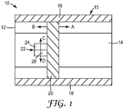
- flying optic (non-scanning) laser processing system 10 includes a fixed and flat table 12 that is mounted to a stable surface such as a floor.
- a workpiece 14 rests on or moves across the table 12 along the direction A.
- a rigid gantry-like mechanism 15 is mounted on the table 12, which includes a crossbar 20 that moves along directions A and B within parallel rail members 16, 18.
- a laser head unit 22 moves in directions C and D along the crossbar 20.
- a laser beam is delivered to the laser head unit 22 by a laser (not shown) along the rail members 16, 18 by an optical train 24. Since the orientation of the beam delivered by the laser head unit 22 is fixed, the parallel rail members 16, 18 should be capable of rapidly moving the crossbar 20 and/or the laser head unit 22 over relatively large distances.
- the parallel rail members 16, 18 and the crossbar 20 should be rigid to quickly and accurately move the laser head unit 22 over the workpiece 14, and as such are bulky and scale in mass with the size of the table 12 and the area of the workpiece 14 to be processed.
- the significant inertia of the components of the gantry mechanism 15 and the laser head unit 22 must be overcome to accelerate and/or change the direction of the laser beam. In the design of the non-scanning laser system 10, it is often the case the laser head unit 22 and the workpiece 14 are relatively close to one another, which limits the potential end uses of the system 10.
- the laser head unit 22 may include a nozzle 28 that is attached to a vacuum system or a source of compressed air.
- additional processing equipment such as the nozzle 28 also add to the mass of the laser head unit 22, which further limits the ability to accelerate and/or change the direction of the laser beam.
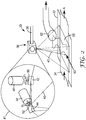
- a scanning laser system 30 in FIG. 2 includes a fixed and flat workpiece handling surface 32 that is fixedly mounted to a stable surface such as a floor.
- a workpiece 34 rests on or moves across the surface 32 along the direction A.
- a laser head unit 36 may be fixed with respect to the table 32 and the workpiece 34, or may be moveable.
- a laser beam 38 is delivered to the laser head unit 36 by a laser (not shown in FIG. 2 ), and traverses an arrangement of small mirrors 42, 44, which form part of a galvanometer scanning unit 41.
- the galvanometer scanning unit 41 may include any number of mirrors 42, 44 as well as focusing optics as required for a particular application, and the arrangement shown in FIG. 2 is merely an example of one design that may be used.
- the mirrors 42, 44 in the galvanometer scanning unit 41 are attached to motors 46, 48 via shafts 50, 52.
- the mirror 42 is rotated though an angle ⁇ 1 by the motor 46, and the mirror 44 is rotated through an angle ⁇ 2 by the motor 48.
- the movement of the mirrors 42, 44 steers a steered laser beam 40 about the workpiece 34. Since the mirrors 42, 44 are small and lightweight, relatively little inertia must be overcome to quickly and accurately move these parts to manipulate the steered laser beam 40, and the steered beam 40 may be quickly accelerated and accurately placed in a processed area 55 on the workpiece 34.
- the working distance between the laser head unit 36 and the workpiece 34 is relatively large compared to the working distance between the laser head unit 22 and the workpiece 14 in the non-scanning system 10 of FIG. 1 .
- debris management on the scanning system 30 can include a fluid supply device 60 to deliver air or water to move ejected particles from the processed area 55 into a vacuum system 62, which keeps the ejected particles from settling on the workpiece 34 and interfering with laser transmission.
- the effectiveness of these global processing methods is limited by the large working distances between the laser head unit 36 and the workpiece 34, which ultimately provide a greater opportunity for any contaminates resulting from the laser processing to settle on and/or stain the processed parts.
- the scanning laser system described in the present disclosure makes it possible to track a laser beam steered by a laser head unit distal the workpiece with a low-inertia end effector selected to perform additional processing functions local (proximal) to the processed area of the workpiece.
- the highly dynamic beam delivery to the processed area provided by the laser scanning system combined with local processing capability in the processed area using the low-inertia end effector, can be important to when rapid and accurate workpiece processing is desired with minimal impact on processing speed.
- a low-inertia nozzle that tracks the scanned laser beam can deliver air or vacuum to the processed area as the laser moves about the workpiece. This localized debris management can more effectively remove particles liberated from the workpiece by the laser, which can improve quality for sensitive products such as display panels, optical films, tapes, and the like.
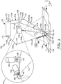
- FIG. 3 illustrates an embodiment of a scanning laser material processing system 100 that includes a fixed and flat workpiece handling surface 102 fixedly mounted to a stable surface such as a floor.
- a workpiece 104 rests on or moves across the workpiece handling surface 102 along the direction A.
- a laser head unit 106 is fixed with respect to the workpiece handling surface 102 and the workpiece 104.
- a laser beam 108 is delivered to the laser head unit 106 by a laser (not shown).
- the galvanometer scanning unit 141 includes an arrangement of motorized mirrors that can be moved to steer the laser beam 108.
- the galvanometer scanning unit 141 may include any number of mirrors as well as focusing optics required for a particular application, and the arrangement shown schematically in FIG. 3 is merely an example of one design that may be used.
- the mirrors 142, 144 in the galvanometer scanning unit 141 are attached to motors 146, 148 via shafts 150, 152.
- the mirror 142 is rotated though an angle ⁇ 1 by the motor 146, and the mirror 144 is rotated through an angle ⁇ 2 by the motor 148.
- the movement of the mirrors 142, 144 may thus be used to direct a steered laser beam 110 about the workpiece 104.
- the mirrors 142, 144 are small and lightweight, relatively little inertia must be overcome to quickly and accurately move these parts to steer the laser beam 110, and the steered beam 110 may be quickly accelerated and accurately placed in a processed area 155 on the workpiece 104.
- the system 100 further includes an end effector 160 that is moved with respect to the workpiece 104 by a robotic manipulator 170.
- the robotic manipulator is a delta robot that includes three axes and can be adapted to move the end effector 160 in any of the x, y and z directions with respect to the workpiece 104 such that the end effector 160 has a full three degrees of freedom.
- the robotic manipulator 170 includes a stationary base 172 and an arrangement of upper arms 174 each having a first end 174A attached to a flexible joint 173 on the stationary base 172.
- the upper arms 174 each have a second end 174B attached to an elbow joint 176, which is in turn connected to a first end 178A of a lower arm 178.
- a second end 178B of each of the lower arms 178 is connected to the end effector 160.
- the end effector 160 tracks within a predetermined standoff distance d the position 156 where the laser beam is incident on the workpiece 104.
- the predetermined standoff distance d may vary widely depending on the intended application of the end effector 160, but the end effector 160 is at all times within a standoff distance d of ⁇ 5 millimeters (mm) of the laser spot 156. In other embodiments, d is ⁇ 0.1 mm of the laser spot 156.
- the end effector 160 may vary widely depending on the intended processing application in the area adjacent to the laser spot 156.
- the end effector 160 may be selected from any type of device with sufficiently low mass such that the robotic manipulator 170 can rapidly move the end effector 160 to track the laser spot 156 on the workpiece 104 with the standoff distance required for a particular application over the required processing area 155.
- the processing area 155 accessible by the end effector 160 is typically about 50 x 50 mm to about 500 x 500 mm (where debris becomes more of an issue in the 250 x 250 mm to 500 x 500 mm range), although many other sizes are possible.
- the end effector 160 should have sufficiently low mass such that the end effector 160 can be accelerated by the robotic manipulator 170 at rates up to 150 m/s per second.
- the end effector 160 typically moves at a velocity of about 1 m/s to about 5 m/s within the processed area 155, which is very useful for converting operations in a manufacturing setting.
- the end effector 160 can optionally be connected to an appropriately flexible cable, tubing, optical fibers, wiring or combination thereof 180 to a source 182.
- the source 182 may be selected from, for example, any or all of the following: a vacuum pump, a source of pressurized fluid such as air, an inert gas, or water, a source of a solid reactant like a powder alloy mixture for sintering on the surface of the workpiece, a source of a liquid chemical that is reactive with the material from which the workpiece is made (or another chemical on the surface of the workpiece), or a radiation source such as ultraviolet (UV) to cause a chemical reaction (for example, curing) on the surface of the workpiece.
- a vacuum pump a source of pressurized fluid such as air, an inert gas, or water
- a source of a solid reactant like a powder alloy mixture for sintering on the surface of the workpiece a source of a liquid chemical that is reactive with the material from which the workpiece is made (or another chemical
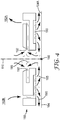
- the end effector 160 of FIG. 4 is a nozzle that is connected via flexible tubing 180 ( FIG. 3 ) to a source 182 that includes vacuum 182A and a pressurized fluid 182B such as air, an inert gas or water.
- a source 182 such as vacuum 182A and a pressurized fluid 182B such as air, an inert gas or water.
- the laser beam 110 processes the workpiece surface 104A and produces a debris plume including particles and fumes 185.
- the particles and fumes 185 can alter the transmission of the laser beam 110 near the surface 104A, potentially cause combustion, and adversely impact the quality of the processed product.
- the end effector 160 includes a fluid supply nozzle portion 190 that directs the pressurized fluid from the fluid supply 182B onto the surface 104A.
- the flow of pressurized fluid from the fluid supply nozzle portion 190 liberates the particles and fumes 185 from the surface 104A.
- the liberated particles and fumes 185 are then entrained in a vacuum stream from the vacuum source 182A and removed from the surface 104A via an arrangement of vacuum nozzles 192.
- the end effector 160 may be selected from, for example, an optical element such as a camera or other lens system, a sensor for inspection of the workpiece during processing, a radiation emitter, a solid or liquid material dispenser, and combinations thereof.
- the end effector described herein works particularly well with laser converting of a workpiece, and can be used to advantage in constrained spaces such as moving web lines and online processing in general.
- the low-mass, high-speed end effectors described herein can be used in any application that can benefit from high-speed local motion, including active local motion (cutting, heating, vacuuming, etc.), or passive local motion (visual inspection, process monitoring, etc.), or a combination of both.
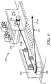
- FIG. 5 is a schematic representation of another embodiment of a scanning laser material processing system 200 that includes a fixed and flat workpiece handling surface 202 fixedly mounted to a stable surface such as a floor.
- a workpiece 204 rests on or moves across the workpiece handling surface 202 along the direction A.
- a laser head unit 206 is fixed with respect to the workpiece handling surface 202 and the workpiece 204.
- a laser beam 208 is delivered to the laser head unit 206 by a laser (not shown).
- the galvanometer scanning unit 241 includes an arrangement of motorized mirrors that can be moved to steer the laser beam 208.
- the galvanometer scanning unit 241 may include any number of mirrors as well as focusing optics as required for a particular application, and the arrangement shown schematically in FIG. 5 is merely an example of one design that may be used.
- the mirrors 242, 244 in the galvanometer scanning unit 241 are attached to motors 246, 248 via shafts 250, 252.
- the mirror 242 is rotated though an angle ⁇ 1 by the motor 246, and the mirror 244 is rotated through an angle ⁇ 2 by the motor 248.
- the movement of the mirrors 242, 244 may thus be used to direct a steered laser beam 210 about the workpiece 204.
- the mirrors 242, 244 are small and lightweight, relatively little inertia must be overcome to quickly and accurately move these parts to direct the steered laser beam 210, and the steered beam 210 may be quickly accelerated and accurately placed in a processed area 255 on the workpiece 204.
- the system 200 further includes an end effector 260 that is moved with respect to the workpiece 204 by a robotic manipulator 270.
- the robotic manipulator 270 is a cable robot manipulated by a plurality of tensioned cables 272. By varying the relative tensions in the cables 272, the position, velocity, and acceleration of the end effector 260 can be accurately controlled to track the laser beam spot 256 on the workpiece 204.
- the cable-suspended morphology of the robotic manipulator 270 reduces further the inertia of the robotic manipulator 270 to only that of the suspension cables 272 and actuator internals (not shown), so the robotic manipulator 270 has lower inertia than the robotic manipulator 170 of FIG. 3 .
- the cable robot 270 can include any number of cables 272, and in the example of FIG. 5 includes four cables and provides three degrees of freedom for movement of the end effector 260. Using seven cables 272, the robot 270 can have up to six degrees of freedom and can be adapted to move the end effector 260 in any of the x, y and z directions (and rotationally) with respect to the workpiece 204.
- the cables 272 each include a first end 272A attached to the end effector 260 and a second end 272B attached to a cable control mechanism 275.
- FIG. 6 shows an example of a cable control mechanism 275 for a single cable 272.
- the cable control mechanism which controls the tension and effective length of the cable 272, includes a motor 276 with an output shaft having mounted thereon a winch drum 278.
- the winch drum 278 engages the second end 272B of the cable 272. After passing through a tension load cell 284 and around a guiding pulley 286, the first end 272A of the cable 272 connects to the end effector 260.
- the end effector 260 does not come into contact with the workpiece 204, but is suspended over the processing area 255 via the tension maintained in the cables 272 by the cable control mechanisms 275. Any droop in the cables 272 due to gravity acting on the end effector 260 can optionally be reduced and/or eliminated by connecting the end effector 260 to flexible tubing 280, which is in turn connected to a source 282 of a pressurized gas such as air. The end effector can then use the pressurized gas exiting the end effector 260 as an air bearing to maintain the end effector 260 above the processing area 255.
- a pressurized gas such as air
- the end effector 260 tracks within a predetermined standoff distance d the position 256 where the laser beam is incident on the workpiece 204.
- the predetermined standoff distance d may vary widely depending on the intended application of the end effector 260, but in some embodiments the end effector 260 is at all times within a standoff distance d of ⁇ 5 millimeters (mm) of the laser spot 256. In other embodiments, d is within ⁇ 0.1 mm of the laser spot 256.
- the end effector 260 may vary widely depending on the intended application, and can be selected from any type of device with sufficiently low mass such that the robotic manipulator 270 can rapidly move the end effector 260 to track the laser spot 256 on the workpiece 204 with the standoff distance required for a particular application (for example, ⁇ 100 mm as noted above) over the required processing area 255.
- the processing area 255 accessible by the end effector 260 using the cable suspended robot 270 is typically about 50 x 50 mm to about 500 x 500 mm, although many other sizes are possible.
- the end effector 260 should have sufficiently low mass such that the end effector 260 can reach velocities of at least about 5 m/s be accelerated by the robotic manipulator 270 at rates up to 200 m/s per second (20 times the force of gravity, G).
- the end effector 260 can optionally be connected to a flexible cable, tubing, optical fibers, wiring or combination thereof 280 to a source 282.
- the source 282 may be selected from, for example, any or all of the following: a vacuum pump, a source of pressurized fluid such as air, an inert gas, or water, a source of a solid reactant like a powder alloy mixture for sintering on the surface of the workpiece, a source of a liquid chemical that is reactive with the material from which the workpiece is made (or another chemical on the surface of the workpiece), or a radiation source such as ultraviolet (UV) to cause a chemical reaction (for example, curing) on the surface of the workpiece.
- a vacuum pump a source of pressurized fluid such as air, an inert gas, or water
- a source of a solid reactant like a powder alloy mixture for sintering on the surface of the workpiece a source of a liquid chemical that is reactive with the material from which the workpiece is made (or
- the end effector 260 may be selected from, for example, an optical element such as a camera or other lens system, a sensor for inspection of the workpiece during processing, a radiation emitter, a solid or liquid material dispenser, and combinations thereof.
- the end effector 260 described herein works particularly well with laser converting of a workpiece, and can be used to advantage in constrained spaces such as moving web lines and online processing in general.
- the low-mass, high-speed end effectors can be used in any application that can benefit from high-speed local motion, including active local motion (cutting, heating, vacuuming, etc.), or passive local motion (visual inspection, process monitoring, etc.) or a combination of both.
- FIG. 7 is a schematic flow diagram illustrating an embodiment of a control unit 300 including a processor configured to cause an end effector 360 to track the movement of a laser beam 310 over the surface of a workpiece 304 (see also FIGS. 5-6 ).
- a control unit 300 includes a trajectory generation module 302 that generates, based on the laser trajectory and parameters 301, power signals for a laser control module 303, trajectory data for a laser head unit control module 304, and robot position data to a robotic manipulator control module 306.
- the laser control module 303 provides laser control signals to a laser controller 307 to power the laser 309.
- the laser head unit control module 304 provides laser head unit control signals to a laser head unit controller 308 as rotational position data for the mirror array in the galvanometer 341, which in turn controls the trajectory with respect to the workpiece 304 of the steered laser beam 310 emitted by the laser 309.
- the robot position data provided by the robotic manipulator control module 306 includes, for example, angular position data for the winch drums and tension data for the cables of the robotic manipulator ( FIGS. 5-6 ).
- the robotic manipulator control module 306 activates a cable mechanism 375 controlling a tension load cell 384 and an arrangement of cables 372.
- the robot position data can be provided to the cable mechanism 375 as rotational data corresponding to winch drum angles (and thus effective cable lengths). These signals can be converted into torque data based on positional feedback for input to the respective tension load cells 384. The above results in the proper relative tension in the respective cables to position the end effector 360 at a location 356 with respect to the workpiece 304 as specified by the imported artwork and parameters 301.
- the laser head unit control signals and the robotic manipulator control signals are coordinated by the processor in the controller 300 such that the end effector 360 tracks the movement of the steered laser beam 310 within a predetermined standoff distance d ( FIG. 5 ) from the position 356 where the laser beam 310 is incident on the workpiece 304.
- the laser head unit control signals and the robotic manipulator control signals may be generated as software instructions executed by one or more processors in the modules of the control unit 300, including one or more hardware microprocessors, digital signal processors (DSPs), application specific integrated circuits (ASICs), field programmable gate arrays (FPGAs), or any other equivalent integrated or discrete logic circuitry, as well as any combinations of such components.
- processors including one or more hardware microprocessors, digital signal processors (DSPs), application specific integrated circuits (ASICs), field programmable gate arrays (FPGAs), or any other equivalent integrated or discrete logic circuitry, as well as any combinations of such components.
- the software instructions may be stored within in a non-transitory computer readable medium, such as random access memory (RAM), read only memory (ROM), programmable read only memory (PROM), erasable programmable read only memory (EPROM), electronically erasable programmable read only memory (EEPROM), flash memory, a hard disk, a CD-ROM, a floppy disk, a cassette, magnetic media, optical media, or other computer-readable storage media.
- RAM random access memory
- ROM read only memory
- PROM programmable read only memory
- EPROM erasable programmable read only memory
- EEPROM electronically erasable programmable read only memory
- flash memory a hard disk, a CD-ROM, a floppy disk, a cassette, magnetic media, optical media, or other computer-readable storage media.
- the processing systems described above are particularly well suited for converting and processing of web materials in a roll-to-roll manufacturing process.
- the workpiece is a moving web of material that is converted at high speeds with scanned lasers, and the low-inertia end effector can be used to further process the area converted by the scanned laser beam.
- the low-inertial material processing systems described herein can be useful in any such high throughput process that can benefit from (or requires) clean converting through laser processing.
- the low-inertial material processing systems herein are useful for clean laser converting of debris-sensitive film products in which the optical quality of the final product is important such as, for example, LCD panels, anti-graffiti films, and tapes.
- the controller 300 of FIG. 7 may be located within a manufacturing plant, or may be located external to the manufacturing plant, or a combination of both e.g., at a central location or at a converting site.
- the described components can execute on a single computing platform or may be integrated into the same software system.
- a material processing system with low-inertia laser scanning and end effector motion was constructed using a 2-axis laser scan head and a 3 degree of freedom cable suspended robot as depicted in FIG. 5 .
- Table 1 provides a list of commercially available equipment used in constructing the example described below.
- the laser scan head listed in Table 1 was mounted with a 204 mm working distance lens resulting in a field size of 140 x 140 mm.
- the cable suspended robot was custom built using the electronics, motors, and drives included in Table 1.
- the four cable guidance assemblies (tension load cells 284 and guiding pulleys 286, FIG. 6 ) were mounted in a rectangular arrangement with the guiding pulleys 286 located at the corners of a 1.4 x 0.83 meter rectangle resulting in an end effector work space of approximately 1.2 x 0.6 meters.
- the material processing system was controlled by the scheme outlined in FIG 7 .
- the components of the control unit 300 were distributed between a local host PC and the embedded controller listed in Table 1 with the two connected via Ethernet.
- the laser control module 303, the laser head unit control module 304, the robotic manipulator control module 306 were implemented on the local host personal computer (PC).
- the laser controller 307 and the laser head unit controller 308 were implemented on the embedded controller utilizing the available FPGA resources.
- Set points for the controllers 307, 308 were computed offline via the modules 303, 304, 306 on the host PC. Given a specified trajectory, Cartesian coordinates were generated by the trajectory generation module 302 for the laser spot position 356 and the position of the end effector nozzle 360. The trajectory generation module 302 also provided the corresponding laser control signals for the laser control module 303 for transmission to the laser controller 307 (i.e., laser output power in Watts), taking into account all necessary delays and offsets.
- the Cartesian coordinates for the galvanometer 341 and the end effector 360 were then passed to the laser head unit control module 304 and the robotic manipulator control module 306 respectively and transformed into the native coordinate systems of the galvanometer 341 and cable controller 375. These native coordinates describe mirror angles for the galvanometer 341 and winch drum rotations for the cable controller 375. For each set point, corresponding optimal tensions were calculated by the robotic manipulator control module 306 based on a specified minimum cable tension as well as the structure matrix of the system determined by the robot's physical characteristics and the position of the end effector 360. We found minimum tension values of 15-20 N to be good values given the setup and expected dynamic performance of the described example.
- the appropriate control signals were generated by the respective controllers 307, 308, 375 running on the FPGA of the embedded controller listed in Table 1.
- the laser controller 307 takes the trajectory power data and generates the corresponding TTL waveform to drive the laser output.
- the laser head unit controller 308 sends the computed galvo mirror angles to the galvo scanner 341 via the XY2-100 scanner protocol; these signals were generated by the 9401 digital I/O module.
- the cable controller 375 takes in the optimal tensions (as torques) as well as the desired winch angular positions and sends appropriate torque values to the tension load cells 384 using the motor drives listed in Table 1 while taking into account feedback from the motor encoders. All torque commands are sent by the cable controller 375 to the tension load cells 384 via the 9516 drive interface modules.
- All trajectory data (set points, laser control, and optimal tensions) was generated at 0.5 millisecond time steps resulting in a 2 kHz update rate.
- the laser controller 307, galvo controller 308, cable controller 375 were run at 20 kHz.
- the executed path consisted of a 40 millimeter square centered about the workspace origin.
- the path began at the origin and moved negatively along the x-axis and positively along the y-axis to the upper-left corner, then moved negatively along the y-axis to the lower-left corner, then positively along the x-axis to the lower-right corner, then positively along the y-axis to the upper-right corner then negatively along the x-axis back to the upper-left corner, then finally back to the origin.
- the trajectory generated by the trajectory generation module 302 was acceleration limited to 150 m/s per second and set to maximize velocity, thus resulting in a piecewise constant acceleration profile, continuous velocity profile, and a continuously differentiable position profile.
- Input coordinates to the laser head unit controller 308 were generated by the laser head unit control module 304 using bilinear interpolation based on collected galvo scanner calibration data.
- Inputs to the cable controller 375 were generated by the robotic manipulator control module 306. These calculations were made based on relative cable lengths resulting from the geometry of the mechanical system including the cable mechanisms and their location within the workspace.
- the coordinates provided by the cable controller 375 were supplemented by optimal static tensions calculated by the robotic manipulator control module 306. These tensions are calculated based on a provided minimum allowed cable tension along with the structure matrix of the system (itself a function of the end effector position).
- the end effector 360 had a mass of 17 grams.
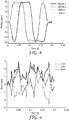
- the output of the system (combined synchronous motion of the laser 309 and the end effector 360) was verified using high speed video capture.
- the real-world Cartesian coordinates from the calibrated video are shown in FIG. 8 , where the position of the end effector 360 along the x and y axes is represented by the solid and dashed lines respectively; the laser spot position along the x and y axes is represented by the dash-dotted and dotted lines respectively.
- the relative positional error between the end effector 360 and the laser spot position 356 is shown in FIG. 9 , where the relative x and y errors are represented by the dashed and dash-dotted lines respectively.
- the solid line depicts the total relative error (square root of sum of squares) of the system along the length of the trajectory. With this particular setup we observed less than 3 mm of relative error along the entirety of the trajectory.
Landscapes
- Engineering & Computer Science (AREA)
- Physics & Mathematics (AREA)
- Optics & Photonics (AREA)
- Mechanical Engineering (AREA)
- Plasma & Fusion (AREA)
- Robotics (AREA)
- Laser Beam Processing (AREA)
- Manipulator (AREA)
Claims (13)
- Système de traitement au laser (100, 200), comprenant :un manipulateur robotique (170, 270) comprenant une base stationnaire (172) ;un effecteur terminal (160, 260, 360) actionné par le manipulateur robotique, dans lequel l'effecteur terminal est adjacent à une pièce de travail (104, 204, 304) ;une unité de tête laser de balayage (106, 206) comprenant un laser (309) et un train optique (141, 241, 341) configuré pour déplacer un faisceau laser (108, 110, 208, 210, 310) par-dessus la pièce de travail jusqu'à une position (156, 256, 356) dans une région d'échantillon (155, 255) de la pièce de travail, dans lequel la tête laser de balayage est fixe par rapport à la pièce de travail ;caractérisé parune unité de commande (300) configurée pour déplacer le manipulateur robotique de telle sorte que l'effecteur terminal suit un mouvement du faisceau laser par-dessus la pièce de travail ;dans lequel le manipulateur robotique (170, 270) est choisi parmi un robot delta et un robot en suspension à un câble ;dans lequel le train optique de l'unité de tête laser de balayage comprend un dispositif de balayage à galvanomètre (141, 241, 341) ;dans lequel l'effecteur terminal (160, 260, 360) est adjacent à la région d'échantillon de la pièce de travail (104, 204, 304), dans lequel l'effecteur terminal est choisi parmi au moins l'un parmi un appareil de gestion de débris, un élément optique, un capteur, un émetteur de rayonnement et un distributeur de matériau, dans lequel un système d'alimentation d'effecteur terminal (182, 282) est relié à l'effecteur terminal ;
etdans lequel l'unité de commande est configurée pour déplacer le manipulateur robotique pour suivre la position du faisceau laser à une distance (d) à plus ou moins 5 millimètres de la position du faisceau laser dans la région d'échantillon de la pièce de travail, dans lequel en outre l'unité de commande (300) comprend un module générateur de trajectoire (302) qui génère, sur la base d'une trajectoire de laser et de paramètres (301), des signaux de puissance permettant à un module de commande de laser (303) de commander le faisceau laser, des données de trajectoire permettant à un module de commande d'unité de tête laser (304) de commander l'unité de tête laser de balayage, et des données de position de robot permettant à un module de commande de manipulateur robotique (306) d'actionner le manipulateur robotique. - Appareil (100, 200) selon la revendication 1, dans lequel l'effecteur terminal (160, 260, 360) comprend un distributeur de matériau, le distributeur de matériau comprenant une buse d'alimentation de gaz inerte ou une tuyère pour distribuer un mélange d'alliage en poudre pour frittage.
- Appareil (100, 200) selon la revendication 1, dans lequel l'effecteur terminal comprend un distributeur de matériau, et le système d'alimentation d'effecteur terminal comprend une source d'un matériau réactif à distribuer sur la pièce de travail par le distributeur de matériau.
- Appareil (100, 200) selon la revendication 1, dans lequel l'effecteur terminal (160, 260, 360) comprend un appareil de gestion de débris, l'appareil de gestion de débris étant choisi parmi une buse soufflante et une buse aspirante.
- Appareil (100, 200) selon la revendication 1, dans lequel l'appareil de gestion de débris comprend une buse aspirante, et le système d'alimentation d'effecteur terminal comprend au moins l'un parmi une source de vide et une alimentation d'un fluide.
- Appareil (100, 200) selon la revendication 1, dans lequel l'effecteur terminal (160, 260, 360) comprend un élément optique, dans lequel l'élément optique comprend une caméra.
- Appareil (100, 200) selon la revendication 1, dans lequel l'effecteur terminal (160, 260, 360) comprend un émetteur de rayonnement, dans lequel l'émetteur de rayonnement comprend une source de rayonnement ultraviolet.
- Appareil (100, 200) selon la revendication 1, dans lequel le manipulateur robotique (170, 270) est un robot delta, éventuellement dans lequel le robot delta inclut un agencement d'au moins trois bras articulés (174, 176, 178) fixés à la base stationnaire (172), dans lequel les bras articulés ont une première extrémité (174A) reliée à la base et une deuxième extrémité (178B) reliée à l'effecteur terminal (160, 260, 360).
- Appareil (100, 200) selon la revendication 1, dans lequel la pièce de travail (104, 240) est non stationnaire par rapport à la base stationnaire (172) du manipulateur robotique (170, 270).
- Procédé de traitement au laser d'une région d'échantillon (155, 255) d'un matériau (104, 204, 304) en temps réel à mesure que le matériau est fabriqué, comprenant :le positionnement d'une unité de tête laser de balayage (106, 206) au-dessus du matériau, dans lequel l'unité de tête laser de balayage comprend un dispositif de balayage à galvanomètre (141, 241, 341) configuré pour déplacer un faisceau laser (108, 110, 208, 210, 310) par-dessus la région d'échantillon du matériau, dans lequel en outre l'unité de tête laser de balayage est fixe par rapport au matériau ; etle positionnement d'un manipulateur robotique (170, 270) adjacent à la région d'échantillon du matériau, dans lequel le manipulateur robotique est relié à un effecteur terminal (160, 260, 360) qui se trouve au-dessus de la région d'échantillon, l'effecteur terminal étant choisi parmi au moins l'un parmi un appareil de gestion de débris, un élément optique, un capteur, un émetteur de rayonnement et un distributeur de matériau ; etla commande du manipulateur robotique pour déplacer l'effecteur terminal de telle sorte que l'effecteur terminal suit un mouvement du faisceau laser par-dessus la région d'échantillon de matériau en temps réel à mesure que le matériau est fabriqué à une distance (d) de plus ou moins 5 millimètres ; dans lequel l'étape de commande est effectuée par une unité de commande (300) comprenant un module générateur de trajectoire (302) qui génère, sur la base d'une trajectoire de laser et de paramètres (301), des signaux de puissance permettant à un module de commande de laser (303) de commander le faisceau laser (108, 110, 208, 210, 310), des données de trajectoire permettant à un module de commande d'unité de tête laser (304) de commander l'unité de tête laser de balayage (106, 206), et des données de position de robot permettant à un module de commande de manipulateur robotique (306) d'actionner le manipulateur robotique (170, 270).
- Procédé selon la revendication 10, dans lequel
le matériau (104, 204, 304) est sous la forme d'une bande ;
l'unité de tête laser de balayage (106, 206) est montée par-dessus la bande ;
le manipulateur robotique (170, 270) est monté par-dessus la bande et le manipulateur robotique est choisi parmi un robot delta et un robot en suspension à un câble ;
l'effecteur terminal (160, 260, 260) est une buse de gestion de débris ; et
la commande du manipulateur robotique pour déplacer l'effecteur terminal déplace la buse de gestion de débris pour éliminer les débris de la surface. - Procédé selon la revendication 11, dans lequel l'appareil de gestion de débris est relié à une source de vide (182A) et à une source d'un gaz (182B).
- Procédé selon la revendication 11, dans lequel la bande (104, 204, 304) et l'unité de tête (106, 206) se déplacent l'une par rapport à l'autre.
Applications Claiming Priority (2)
| Application Number | Priority Date | Filing Date | Title |
|---|---|---|---|
| US201261740340P | 2012-12-20 | 2012-12-20 | |
| PCT/US2013/074233 WO2014107274A1 (fr) | 2012-12-20 | 2013-12-11 | Manipulation d'un effecteur terminal par balayage laser à faible inertie pour le traitement d'un matériau |
Publications (3)
| Publication Number | Publication Date |
|---|---|
| EP2934812A1 EP2934812A1 (fr) | 2015-10-28 |
| EP2934812A4 EP2934812A4 (fr) | 2016-08-24 |
| EP2934812B1 true EP2934812B1 (fr) | 2019-12-11 |
Family
ID=51062417
Family Applications (1)
| Application Number | Title | Priority Date | Filing Date |
|---|---|---|---|
| EP13870028.1A Active EP2934812B1 (fr) | 2012-12-20 | 2013-12-11 | Manipulation d'un effecteur terminal par balayage laser à faible inertie pour le traitement d'un matériau |
Country Status (7)
| Country | Link |
|---|---|
| US (1) | US10399178B2 (fr) |
| EP (1) | EP2934812B1 (fr) |
| JP (1) | JP6382220B2 (fr) |
| KR (2) | KR102249405B1 (fr) |
| CN (1) | CN104870140B (fr) |
| BR (1) | BR112015014893A2 (fr) |
| WO (1) | WO2014107274A1 (fr) |
Families Citing this family (13)
| Publication number | Priority date | Publication date | Assignee | Title |
|---|---|---|---|---|
| US10788836B2 (en) * | 2016-02-29 | 2020-09-29 | AI Incorporated | Obstacle recognition method for autonomous robots |
| JP6035461B1 (ja) * | 2016-04-28 | 2016-11-30 | 武井電機工業株式会社 | レーザー加工方法及びレーザー加工装置 |
| JP6829053B2 (ja) * | 2016-11-09 | 2021-02-10 | コマツ産機株式会社 | マシンルーム |
| JP6496340B2 (ja) * | 2017-03-17 | 2019-04-03 | ファナック株式会社 | スキャナ制御装置、ロボット制御装置及びリモートレーザ溶接ロボットシステム |
| DE102017111244A1 (de) * | 2017-05-23 | 2018-12-13 | ConsultEngineerIP AG | Quasi-Simultaner Laser-Schweissprozess |
| JP6852031B2 (ja) * | 2018-09-26 | 2021-03-31 | 株式会社東芝 | 溶接装置及びノズル装置 |
| EP3870394B1 (fr) * | 2018-10-25 | 2022-03-09 | 3M Innovative Properties Company | Systèmes et procédés de commande de force d'actionneur conformes à plusieurs degrés de liberté utilisés dans la réparation de peinture robotique |
| IT201900000995A1 (it) * | 2019-01-23 | 2020-07-23 | Nuovo Pignone Tecnologie Srl | Apparecchiatura robotica industriale con generazione di percorso di lavorazione migliorata e metodo per azionare un' apparecchiatura robotica industriale secondo un percorso di lavorazione migliorato |
| DE102019103659B4 (de) * | 2019-02-13 | 2023-11-30 | Bystronic Laser Ag | Gasführung, Laserschneidkopf und Laserschneidmaschine |
| CN109807475A (zh) * | 2019-03-26 | 2019-05-28 | 广西加一米科技有限公司 | 铝带激光连续切割机组 |
| EP3984688A1 (fr) * | 2020-10-16 | 2022-04-20 | Bystronic Laser AG | Méthode, programme ordinateur et système de coupage par laser pour coupage intelligent dans un angle |
| CN115555852B (zh) * | 2021-06-30 | 2023-06-30 | 宁德时代新能源科技股份有限公司 | 极片成型方法及设备 |
| US20230249291A1 (en) * | 2022-02-09 | 2023-08-10 | Ford Global Technologies, Llc | Laser notching apparatus for cutting of electrode sheets |
Citations (4)
| Publication number | Priority date | Publication date | Assignee | Title |
|---|---|---|---|---|
| JPH06114443A (ja) * | 1991-08-29 | 1994-04-26 | Okuma Mach Works Ltd | 板金加工方法及びその機械 |
| JP2005177786A (ja) * | 2003-12-17 | 2005-07-07 | Denso Corp | 高密度エネルギビーム加工方法及びその装置、孔付き管の製造方法及びその装置 |
| US20100176539A1 (en) * | 2007-10-26 | 2010-07-15 | Panasonic Electric Works Co., Ltd. | Manufacturing method of three-dimensionally shaped object |
| DE102011016519A1 (de) * | 2011-04-08 | 2012-10-11 | Lessmüller Lasertechnik GmbH | Verfahren und Vorrichtung zum Steuern der Bearbeitung eines Werkstücks mittels eines hochenergetischen Bearbeitungsstrahls |
Family Cites Families (19)
| Publication number | Priority date | Publication date | Assignee | Title |
|---|---|---|---|---|
| US5204517A (en) * | 1991-12-24 | 1993-04-20 | Maxwell Laboratories, Inc. | Method and system for control of a material removal process using spectral emission discrimination |
| JP2917763B2 (ja) * | 1993-08-11 | 1999-07-12 | 日産自動車株式会社 | 肉盛溶接における溶接金属粉末供給方法及びその装置 |
| US6427096B1 (en) * | 1999-02-12 | 2002-07-30 | Honeywell International Inc. | Processing tool interface apparatus for use in manufacturing environment |
| US20020104833A1 (en) * | 2001-02-08 | 2002-08-08 | Automated Welding Systems Inc. | Welding head mount for robotic welding apparatus with micro adjustment capability |
| US20040034599A1 (en) | 2001-06-01 | 2004-02-19 | Pietro Ferrero | Method and device for the robot-controlled cutting of workpieces to be assembled by means of laser radiation |
| JP2003181663A (ja) * | 2001-12-11 | 2003-07-02 | Mitsubishi Heavy Ind Ltd | 複合溶接方法および複合溶接ヘッド |
| DE10204993B4 (de) | 2002-02-05 | 2005-06-09 | Jenoptik Automatisierungstechnik Gmbh | Vorrichtung zum Bearbeiten von dreidimensional ausgedehnten Werkstückoberflächen mittels Laser |
| GB2390319B (en) * | 2002-07-03 | 2005-07-27 | Rolls Royce Plc | Method and apparatus for laser welding |
| JP4922584B2 (ja) * | 2004-12-10 | 2012-04-25 | 株式会社安川電機 | ロボットシステム |
| JP2007044726A (ja) | 2005-08-09 | 2007-02-22 | Nissan Motor Co Ltd | レーザ溶接装置および溶接方法 |
| CN100409994C (zh) * | 2005-10-14 | 2008-08-13 | 江苏大学 | 基于激光冲击技术的水约束层增压的方法和装置 |
| JP2009045625A (ja) * | 2007-08-13 | 2009-03-05 | Fuji Electric Systems Co Ltd | レーザ加工装置 |
| DE102007062212A1 (de) | 2007-12-21 | 2009-06-25 | Linde Ag | Verfahren und Vorrichtung zum Laser-Remote-Schneiden |
| JP5262810B2 (ja) | 2009-02-18 | 2013-08-14 | 村田機械株式会社 | パラレルメカニズム |
| EP2491583B1 (fr) * | 2009-10-19 | 2017-11-22 | M-Solv Ltd | Appareil pour le traitement de longueurs continues de feuille souple |
| JP2011125877A (ja) | 2009-12-16 | 2011-06-30 | Mitsubishi Heavy Ind Ltd | レーザ加工方法及び装置 |
| JP5609500B2 (ja) | 2010-10-01 | 2014-10-22 | スズキ株式会社 | レーザ溶接装置 |
| CN202278307U (zh) * | 2011-08-19 | 2012-06-20 | 广州有色金属研究院 | 一种可调式双线结构光焊缝跟踪视觉传感系统 |
| CN102825383B (zh) * | 2012-07-19 | 2014-10-29 | 宁海县盛源激光科技有限公司 | 一种数控半导体激光加工机床 |
-
2013
- 2013-12-11 WO PCT/US2013/074233 patent/WO2014107274A1/fr active Application Filing
- 2013-12-11 KR KR1020207031772A patent/KR102249405B1/ko active IP Right Grant
- 2013-12-11 US US14/653,921 patent/US10399178B2/en active Active
- 2013-12-11 KR KR1020157019370A patent/KR20150096766A/ko not_active IP Right Cessation
- 2013-12-11 JP JP2015549469A patent/JP6382220B2/ja active Active
- 2013-12-11 EP EP13870028.1A patent/EP2934812B1/fr active Active
- 2013-12-11 BR BR112015014893A patent/BR112015014893A2/pt not_active IP Right Cessation
- 2013-12-11 CN CN201380066463.1A patent/CN104870140B/zh active Active
Patent Citations (4)
| Publication number | Priority date | Publication date | Assignee | Title |
|---|---|---|---|---|
| JPH06114443A (ja) * | 1991-08-29 | 1994-04-26 | Okuma Mach Works Ltd | 板金加工方法及びその機械 |
| JP2005177786A (ja) * | 2003-12-17 | 2005-07-07 | Denso Corp | 高密度エネルギビーム加工方法及びその装置、孔付き管の製造方法及びその装置 |
| US20100176539A1 (en) * | 2007-10-26 | 2010-07-15 | Panasonic Electric Works Co., Ltd. | Manufacturing method of three-dimensionally shaped object |
| DE102011016519A1 (de) * | 2011-04-08 | 2012-10-11 | Lessmüller Lasertechnik GmbH | Verfahren und Vorrichtung zum Steuern der Bearbeitung eines Werkstücks mittels eines hochenergetischen Bearbeitungsstrahls |
Also Published As
| Publication number | Publication date |
|---|---|
| JP2016505389A (ja) | 2016-02-25 |
| KR20200129167A (ko) | 2020-11-17 |
| WO2014107274A1 (fr) | 2014-07-10 |
| KR102249405B1 (ko) | 2021-05-07 |
| EP2934812A4 (fr) | 2016-08-24 |
| KR20150096766A (ko) | 2015-08-25 |
| CN104870140A (zh) | 2015-08-26 |
| US20150352667A1 (en) | 2015-12-10 |
| EP2934812A1 (fr) | 2015-10-28 |
| JP6382220B2 (ja) | 2018-08-29 |
| BR112015014893A2 (pt) | 2017-07-11 |
| CN104870140B (zh) | 2018-05-22 |
| US10399178B2 (en) | 2019-09-03 |
Similar Documents
| Publication | Publication Date | Title |
|---|---|---|
| EP2934812B1 (fr) | Manipulation d'un effecteur terminal par balayage laser à faible inertie pour le traitement d'un matériau | |
| CN106794517B (zh) | 用于通过激光烧结来添加制造的激光操作机器及对应的方法 | |
| JP5316124B2 (ja) | レーザー溶接装置 | |
| US4626999A (en) | Apparatus for controlled manipulation of laser focus point | |
| US8921734B2 (en) | Laser cutting machine | |
| US8820203B2 (en) | Method of controlling a robot for small shape generation | |
| US4661680A (en) | End-of-arm tooling carousel apparatus for use with a robot | |
| KR20130007446A (ko) | 도장 시스템 | |
| US11772116B2 (en) | Multiple fourth axis robot | |
| CN211275752U (zh) | 一种在线激光清洗装置 | |
| JPH03492A (ja) | レーザー装置 | |
| WO2015179989A1 (fr) | Appareil et procédé de traitement laser d'une pièce de travail sur une surface tridimensionnelle | |
| JP2003230975A (ja) | レーザーを用いて3次元的に広がる加工品表面を加工するための装置 | |
| RU2368473C2 (ru) | Устройство для перемещения обрабатывающего инструмента (варианты) | |
| JPH10216981A (ja) | 光軸移動型レーザー加工装置 | |
| RU208976U1 (ru) | Мобильный робот для обработки поверхностей крупногабаритных стационарных объектов | |
| JPH05216516A (ja) | レーザ加工機 | |
| Geving et al. | Enhancement of stereo-lithography technology to support building around inserts | |
| US11654562B2 (en) | Apparatus, robot control device, robot system, and method of setting robot coordinate system | |
| JP4974859B2 (ja) | ロボット制御装置 | |
| JP7414426B2 (ja) | ロボットシステム | |
| US20230036260A1 (en) | Control method for robot system and robot system | |
| EP4088855B1 (fr) | Effecteur d'extrémité de module laser pour dispositif robotique | |
| Ryuh et al. | Arc welding robot automation systems | |
| CN116568466A (zh) | 使多个移动机械移动并进行规定的作业的控制装置、机械系统、方法以及计算机程序 |
Legal Events
| Date | Code | Title | Description |
|---|---|---|---|
| PUAI | Public reference made under article 153(3) epc to a published international application that has entered the european phase |
Free format text: ORIGINAL CODE: 0009012 |
|
| 17P | Request for examination filed |
Effective date: 20150618 |
|
| AK | Designated contracting states |
Kind code of ref document: A1 Designated state(s): AL AT BE BG CH CY CZ DE DK EE ES FI FR GB GR HR HU IE IS IT LI LT LU LV MC MK MT NL NO PL PT RO RS SE SI SK SM TR |
|
| AX | Request for extension of the european patent |
Extension state: BA ME |
|
| DAX | Request for extension of the european patent (deleted) | ||
| A4 | Supplementary search report drawn up and despatched |
Effective date: 20160722 |
|
| RIC1 | Information provided on ipc code assigned before grant |
Ipc: B23K 26/142 20140101ALI20160718BHEP Ipc: G05B 19/18 20060101ALI20160718BHEP Ipc: B23K 26/082 20140101ALI20160718BHEP Ipc: B23K 26/03 20060101ALI20160718BHEP Ipc: B23K 26/34 20140101AFI20160718BHEP Ipc: B23K 26/144 20140101ALI20160718BHEP Ipc: B25J 9/16 20060101ALI20160718BHEP |
|
| STAA | Information on the status of an ep patent application or granted ep patent |
Free format text: STATUS: EXAMINATION IS IN PROGRESS |
|
| 17Q | First examination report despatched |
Effective date: 20181114 |
|
| GRAP | Despatch of communication of intention to grant a patent |
Free format text: ORIGINAL CODE: EPIDOSNIGR1 |
|
| STAA | Information on the status of an ep patent application or granted ep patent |
Free format text: STATUS: GRANT OF PATENT IS INTENDED |
|
| INTG | Intention to grant announced |
Effective date: 20190701 |
|
| GRAS | Grant fee paid |
Free format text: ORIGINAL CODE: EPIDOSNIGR3 |
|
| GRAA | (expected) grant |
Free format text: ORIGINAL CODE: 0009210 |
|
| STAA | Information on the status of an ep patent application or granted ep patent |
Free format text: STATUS: THE PATENT HAS BEEN GRANTED |
|
| AK | Designated contracting states |
Kind code of ref document: B1 Designated state(s): AL AT BE BG CH CY CZ DE DK EE ES FI FR GB GR HR HU IE IS IT LI LT LU LV MC MK MT NL NO PL PT RO RS SE SI SK SM TR |
|
| REG | Reference to a national code |
Ref country code: GB Ref legal event code: FG4D |
|
| REG | Reference to a national code |
Ref country code: CH Ref legal event code: EP |
|
| REG | Reference to a national code |
Ref country code: AT Ref legal event code: REF Ref document number: 1211718 Country of ref document: AT Kind code of ref document: T Effective date: 20191215 |
|
| REG | Reference to a national code |
Ref country code: DE Ref legal event code: R096 Ref document number: 602013063988 Country of ref document: DE |
|
| REG | Reference to a national code |
Ref country code: IE Ref legal event code: FG4D |
|
| REG | Reference to a national code |
Ref country code: NL Ref legal event code: MP Effective date: 20191211 |
|
| REG | Reference to a national code |
Ref country code: LT Ref legal event code: MG4D |
|
| PG25 | Lapsed in a contracting state [announced via postgrant information from national office to epo] |
Ref country code: BG Free format text: LAPSE BECAUSE OF FAILURE TO SUBMIT A TRANSLATION OF THE DESCRIPTION OR TO PAY THE FEE WITHIN THE PRESCRIBED TIME-LIMIT Effective date: 20200311 Ref country code: FI Free format text: LAPSE BECAUSE OF FAILURE TO SUBMIT A TRANSLATION OF THE DESCRIPTION OR TO PAY THE FEE WITHIN THE PRESCRIBED TIME-LIMIT Effective date: 20191211 Ref country code: LV Free format text: LAPSE BECAUSE OF FAILURE TO SUBMIT A TRANSLATION OF THE DESCRIPTION OR TO PAY THE FEE WITHIN THE PRESCRIBED TIME-LIMIT Effective date: 20191211 Ref country code: SE Free format text: LAPSE BECAUSE OF FAILURE TO SUBMIT A TRANSLATION OF THE DESCRIPTION OR TO PAY THE FEE WITHIN THE PRESCRIBED TIME-LIMIT Effective date: 20191211 Ref country code: GR Free format text: LAPSE BECAUSE OF FAILURE TO SUBMIT A TRANSLATION OF THE DESCRIPTION OR TO PAY THE FEE WITHIN THE PRESCRIBED TIME-LIMIT Effective date: 20200312 Ref country code: NO Free format text: LAPSE BECAUSE OF FAILURE TO SUBMIT A TRANSLATION OF THE DESCRIPTION OR TO PAY THE FEE WITHIN THE PRESCRIBED TIME-LIMIT Effective date: 20200311 Ref country code: LT Free format text: LAPSE BECAUSE OF FAILURE TO SUBMIT A TRANSLATION OF THE DESCRIPTION OR TO PAY THE FEE WITHIN THE PRESCRIBED TIME-LIMIT Effective date: 20191211 |
|
| PG25 | Lapsed in a contracting state [announced via postgrant information from national office to epo] |
Ref country code: HR Free format text: LAPSE BECAUSE OF FAILURE TO SUBMIT A TRANSLATION OF THE DESCRIPTION OR TO PAY THE FEE WITHIN THE PRESCRIBED TIME-LIMIT Effective date: 20191211 Ref country code: RS Free format text: LAPSE BECAUSE OF FAILURE TO SUBMIT A TRANSLATION OF THE DESCRIPTION OR TO PAY THE FEE WITHIN THE PRESCRIBED TIME-LIMIT Effective date: 20191211 |
|
| PG25 | Lapsed in a contracting state [announced via postgrant information from national office to epo] |
Ref country code: AL Free format text: LAPSE BECAUSE OF FAILURE TO SUBMIT A TRANSLATION OF THE DESCRIPTION OR TO PAY THE FEE WITHIN THE PRESCRIBED TIME-LIMIT Effective date: 20191211 |
|
| PG25 | Lapsed in a contracting state [announced via postgrant information from national office to epo] |
Ref country code: NL Free format text: LAPSE BECAUSE OF FAILURE TO SUBMIT A TRANSLATION OF THE DESCRIPTION OR TO PAY THE FEE WITHIN THE PRESCRIBED TIME-LIMIT Effective date: 20191211 Ref country code: EE Free format text: LAPSE BECAUSE OF FAILURE TO SUBMIT A TRANSLATION OF THE DESCRIPTION OR TO PAY THE FEE WITHIN THE PRESCRIBED TIME-LIMIT Effective date: 20191211 Ref country code: ES Free format text: LAPSE BECAUSE OF FAILURE TO SUBMIT A TRANSLATION OF THE DESCRIPTION OR TO PAY THE FEE WITHIN THE PRESCRIBED TIME-LIMIT Effective date: 20191211 Ref country code: RO Free format text: LAPSE BECAUSE OF FAILURE TO SUBMIT A TRANSLATION OF THE DESCRIPTION OR TO PAY THE FEE WITHIN THE PRESCRIBED TIME-LIMIT Effective date: 20191211 Ref country code: CZ Free format text: LAPSE BECAUSE OF FAILURE TO SUBMIT A TRANSLATION OF THE DESCRIPTION OR TO PAY THE FEE WITHIN THE PRESCRIBED TIME-LIMIT Effective date: 20191211 Ref country code: PT Free format text: LAPSE BECAUSE OF FAILURE TO SUBMIT A TRANSLATION OF THE DESCRIPTION OR TO PAY THE FEE WITHIN THE PRESCRIBED TIME-LIMIT Effective date: 20200506 |
|
| REG | Reference to a national code |
Ref country code: CH Ref legal event code: PL |
|
| REG | Reference to a national code |
Ref country code: BE Ref legal event code: MM Effective date: 20191231 |
|
| PG25 | Lapsed in a contracting state [announced via postgrant information from national office to epo] |
Ref country code: SK Free format text: LAPSE BECAUSE OF FAILURE TO SUBMIT A TRANSLATION OF THE DESCRIPTION OR TO PAY THE FEE WITHIN THE PRESCRIBED TIME-LIMIT Effective date: 20191211 Ref country code: IS Free format text: LAPSE BECAUSE OF FAILURE TO SUBMIT A TRANSLATION OF THE DESCRIPTION OR TO PAY THE FEE WITHIN THE PRESCRIBED TIME-LIMIT Effective date: 20200411 Ref country code: SM Free format text: LAPSE BECAUSE OF FAILURE TO SUBMIT A TRANSLATION OF THE DESCRIPTION OR TO PAY THE FEE WITHIN THE PRESCRIBED TIME-LIMIT Effective date: 20191211 |
|
| REG | Reference to a national code |
Ref country code: DE Ref legal event code: R097 Ref document number: 602013063988 Country of ref document: DE |
|
| PG25 | Lapsed in a contracting state [announced via postgrant information from national office to epo] |
Ref country code: MC Free format text: LAPSE BECAUSE OF FAILURE TO SUBMIT A TRANSLATION OF THE DESCRIPTION OR TO PAY THE FEE WITHIN THE PRESCRIBED TIME-LIMIT Effective date: 20191211 |
|
| REG | Reference to a national code |
Ref country code: AT Ref legal event code: MK05 Ref document number: 1211718 Country of ref document: AT Kind code of ref document: T Effective date: 20191211 |
|
| PLBE | No opposition filed within time limit |
Free format text: ORIGINAL CODE: 0009261 |
|
| STAA | Information on the status of an ep patent application or granted ep patent |
Free format text: STATUS: NO OPPOSITION FILED WITHIN TIME LIMIT |
|
| PG25 | Lapsed in a contracting state [announced via postgrant information from national office to epo] |
Ref country code: DK Free format text: LAPSE BECAUSE OF FAILURE TO SUBMIT A TRANSLATION OF THE DESCRIPTION OR TO PAY THE FEE WITHIN THE PRESCRIBED TIME-LIMIT Effective date: 20191211 Ref country code: IE Free format text: LAPSE BECAUSE OF NON-PAYMENT OF DUE FEES Effective date: 20191211 Ref country code: LU Free format text: LAPSE BECAUSE OF NON-PAYMENT OF DUE FEES Effective date: 20191211 |
|
| 26N | No opposition filed |
Effective date: 20200914 |
|
| PG25 | Lapsed in a contracting state [announced via postgrant information from national office to epo] |
Ref country code: LI Free format text: LAPSE BECAUSE OF NON-PAYMENT OF DUE FEES Effective date: 20191231 Ref country code: AT Free format text: LAPSE BECAUSE OF FAILURE TO SUBMIT A TRANSLATION OF THE DESCRIPTION OR TO PAY THE FEE WITHIN THE PRESCRIBED TIME-LIMIT Effective date: 20191211 Ref country code: CH Free format text: LAPSE BECAUSE OF NON-PAYMENT OF DUE FEES Effective date: 20191231 Ref country code: SI Free format text: LAPSE BECAUSE OF FAILURE TO SUBMIT A TRANSLATION OF THE DESCRIPTION OR TO PAY THE FEE WITHIN THE PRESCRIBED TIME-LIMIT Effective date: 20191211 Ref country code: BE Free format text: LAPSE BECAUSE OF NON-PAYMENT OF DUE FEES Effective date: 20191231 Ref country code: PL Free format text: LAPSE BECAUSE OF FAILURE TO SUBMIT A TRANSLATION OF THE DESCRIPTION OR TO PAY THE FEE WITHIN THE PRESCRIBED TIME-LIMIT Effective date: 20191211 |
|
| PG25 | Lapsed in a contracting state [announced via postgrant information from national office to epo] |
Ref country code: IT Free format text: LAPSE BECAUSE OF FAILURE TO SUBMIT A TRANSLATION OF THE DESCRIPTION OR TO PAY THE FEE WITHIN THE PRESCRIBED TIME-LIMIT Effective date: 20191211 Ref country code: FR Free format text: LAPSE BECAUSE OF NON-PAYMENT OF DUE FEES Effective date: 20200211 |
|
| GBPC | Gb: european patent ceased through non-payment of renewal fee |
Effective date: 20200311 |
|
| PG25 | Lapsed in a contracting state [announced via postgrant information from national office to epo] |
Ref country code: GB Free format text: LAPSE BECAUSE OF NON-PAYMENT OF DUE FEES Effective date: 20200311 |
|
| PG25 | Lapsed in a contracting state [announced via postgrant information from national office to epo] |
Ref country code: CY Free format text: LAPSE BECAUSE OF FAILURE TO SUBMIT A TRANSLATION OF THE DESCRIPTION OR TO PAY THE FEE WITHIN THE PRESCRIBED TIME-LIMIT Effective date: 20191211 |
|
| PG25 | Lapsed in a contracting state [announced via postgrant information from national office to epo] |
Ref country code: HU Free format text: LAPSE BECAUSE OF FAILURE TO SUBMIT A TRANSLATION OF THE DESCRIPTION OR TO PAY THE FEE WITHIN THE PRESCRIBED TIME-LIMIT; INVALID AB INITIO Effective date: 20131211 Ref country code: MT Free format text: LAPSE BECAUSE OF FAILURE TO SUBMIT A TRANSLATION OF THE DESCRIPTION OR TO PAY THE FEE WITHIN THE PRESCRIBED TIME-LIMIT Effective date: 20191211 |
|
| PG25 | Lapsed in a contracting state [announced via postgrant information from national office to epo] |
Ref country code: TR Free format text: LAPSE BECAUSE OF FAILURE TO SUBMIT A TRANSLATION OF THE DESCRIPTION OR TO PAY THE FEE WITHIN THE PRESCRIBED TIME-LIMIT Effective date: 20191211 |
|
| PG25 | Lapsed in a contracting state [announced via postgrant information from national office to epo] |
Ref country code: MK Free format text: LAPSE BECAUSE OF FAILURE TO SUBMIT A TRANSLATION OF THE DESCRIPTION OR TO PAY THE FEE WITHIN THE PRESCRIBED TIME-LIMIT Effective date: 20191211 |
|
| P01 | Opt-out of the competence of the unified patent court (upc) registered |
Effective date: 20230530 |
|
| PGFP | Annual fee paid to national office [announced via postgrant information from national office to epo] |
Ref country code: DE Payment date: 20231121 Year of fee payment: 11 |