EP2933512B1 - Magnetic bearing arrangement and method of operating a magnetic bearing arrangement - Google Patents
Magnetic bearing arrangement and method of operating a magnetic bearing arrangement Download PDFInfo
- Publication number
- EP2933512B1 EP2933512B1 EP14164597.8A EP14164597A EP2933512B1 EP 2933512 B1 EP2933512 B1 EP 2933512B1 EP 14164597 A EP14164597 A EP 14164597A EP 2933512 B1 EP2933512 B1 EP 2933512B1
- Authority
- EP
- European Patent Office
- Prior art keywords
- electromagnet
- force
- arrangement
- control module
- electromagnets
- Prior art date
- Legal status (The legal status is an assumption and is not a legal conclusion. Google has not performed a legal analysis and makes no representation as to the accuracy of the status listed.)
- Active
Links
Images
Classifications
-
- F—MECHANICAL ENGINEERING; LIGHTING; HEATING; WEAPONS; BLASTING
- F16—ENGINEERING ELEMENTS AND UNITS; GENERAL MEASURES FOR PRODUCING AND MAINTAINING EFFECTIVE FUNCTIONING OF MACHINES OR INSTALLATIONS; THERMAL INSULATION IN GENERAL
- F16C—SHAFTS; FLEXIBLE SHAFTS; ELEMENTS OR CRANKSHAFT MECHANISMS; ROTARY BODIES OTHER THAN GEARING ELEMENTS; BEARINGS
- F16C32/00—Bearings not otherwise provided for
- F16C32/04—Bearings not otherwise provided for using magnetic or electric supporting means
- F16C32/0406—Magnetic bearings
- F16C32/044—Active magnetic bearings
- F16C32/0444—Details of devices to control the actuation of the electromagnets
- F16C32/0457—Details of the power supply to the electromagnets
-
- F—MECHANICAL ENGINEERING; LIGHTING; HEATING; WEAPONS; BLASTING
- F16—ENGINEERING ELEMENTS AND UNITS; GENERAL MEASURES FOR PRODUCING AND MAINTAINING EFFECTIVE FUNCTIONING OF MACHINES OR INSTALLATIONS; THERMAL INSULATION IN GENERAL
- F16C—SHAFTS; FLEXIBLE SHAFTS; ELEMENTS OR CRANKSHAFT MECHANISMS; ROTARY BODIES OTHER THAN GEARING ELEMENTS; BEARINGS
- F16C32/00—Bearings not otherwise provided for
- F16C32/04—Bearings not otherwise provided for using magnetic or electric supporting means
- F16C32/0406—Magnetic bearings
- F16C32/044—Active magnetic bearings
- F16C32/0444—Details of devices to control the actuation of the electromagnets
- F16C32/0446—Determination of the actual position of the moving member, e.g. details of sensors
-
- F—MECHANICAL ENGINEERING; LIGHTING; HEATING; WEAPONS; BLASTING
- F16—ENGINEERING ELEMENTS AND UNITS; GENERAL MEASURES FOR PRODUCING AND MAINTAINING EFFECTIVE FUNCTIONING OF MACHINES OR INSTALLATIONS; THERMAL INSULATION IN GENERAL
- F16C—SHAFTS; FLEXIBLE SHAFTS; ELEMENTS OR CRANKSHAFT MECHANISMS; ROTARY BODIES OTHER THAN GEARING ELEMENTS; BEARINGS
- F16C32/00—Bearings not otherwise provided for
- F16C32/04—Bearings not otherwise provided for using magnetic or electric supporting means
- F16C32/0406—Magnetic bearings
- F16C32/044—Active magnetic bearings
- F16C32/0444—Details of devices to control the actuation of the electromagnets
- F16C32/0451—Details of controllers, i.e. the units determining the power to be supplied, e.g. comparing elements, feedback arrangements with P.I.D. control
-
- F—MECHANICAL ENGINEERING; LIGHTING; HEATING; WEAPONS; BLASTING
- F16—ENGINEERING ELEMENTS AND UNITS; GENERAL MEASURES FOR PRODUCING AND MAINTAINING EFFECTIVE FUNCTIONING OF MACHINES OR INSTALLATIONS; THERMAL INSULATION IN GENERAL
- F16C—SHAFTS; FLEXIBLE SHAFTS; ELEMENTS OR CRANKSHAFT MECHANISMS; ROTARY BODIES OTHER THAN GEARING ELEMENTS; BEARINGS
- F16C32/00—Bearings not otherwise provided for
- F16C32/04—Bearings not otherwise provided for using magnetic or electric supporting means
- F16C32/0406—Magnetic bearings
- F16C32/044—Active magnetic bearings
- F16C32/0474—Active magnetic bearings for rotary movement
Definitions
- the invention relates generally to magnetic bearing arrangements and to methods of operating such magnetic bearing arrangements.
- Active magnetic bearings are used to suspend shafts of rotating equipment subject to load spectra which vary with respect to time. Control of the position of the rotating assemblies of such equipment is effectuated by electromechanical systems which combine the use of feedback control and switching amplifiers such as voltage source inverters. Typically, the feedback control is based on an outer position control and an inner current control. The inner current control generates PWM (Pulse Width Modulation) signals to the switching amplifier which provides the desired currents as indicated by the outer position control.
- PWM Pulse Width Modulation
- Active magnetic bearings may e.g. be used in high speed rotation applications, especially in high power compressors for oil and gas applications.
- JP 2010 200524 discloses a motor controller.
- a power failure detector detects power failure
- a bearingless motor is decelerated in a drive-side control circuit by switching a rotational angle speed command value to zero with a changeover switch, and a drive-side inverter is controlled so that the generated power of the bearingless motor is regenerated from the bearingless motor to a DC link circuit side via the drive-side inverter.
- This regenerative power is supplied to an inverter on a shaft support side via the DC link circuit.
- a negative lower limit setting value is output in a limiter lower limit value adjusting circuit when a DC link voltage value detected by a voltage detector is lower than a DC link voltage setting value, and this negative lower limit setting value is set as a lower limit setting value of a variable limiter in the variable limiter.
- Standard motor drives have been widely used and are thoroughly verified in industry for long time and could be a good choice as switching amplifiers for active magnetic bearings.
- IGBT's Insulated-Gate Bipolar Transistors
- they have limited maximum switching frequency, e.g. up to about 16 kHz for drive ACS M 1 commercially available from ABB. This limits naturally the force bandwidth of active magnetic bearings if current control based on PWM is used.
- the fixed switching frequency used in PWM limits the amplifier bandwidth, because the amplifier has to wait for the next switching period to respond to changes.
- the limited amplifier bandwidth in turn limits the force bandwidth.
- the amplifier bandwidth can be around 300 to 400Hz, which means that the maximum motor speed will be limited to around 20000 rpm or even lower because of amplifier delay. This means that the applicability for high speed applications is reduced significantly.
- An aim of the present invention is to provide an electromagnetic bearing arrangement and a method of operating an electromagnetic bearing arrangement, wherein the force bandwidth can be high when using standard motor drives as switching amplifiers.
- an electromagnetic bearing arrangement for a rotating equipment, the electromagnetic bearing arrangement comprising an electromagnet, an amplifier arrangement based on IGBT switches, a power supply for powering the amplifier arrangement, a controller for controlling the amplifier arrangement to operate the electromagnet, and a position sensor for measuring the position of the rotating equipment in relation to the electromagnet.
- the controller comprises a position control module and a direct force control module, wherein the position sensor is operatively connected to the position control module to forward the measured position of the rotating equipment in relation to the electromagnet to the position control module and the position control module is configured to calculate a force reference based on the measured position of the rotating equipment in relation to the electromagnet.
- the electromagnetic bearing arrangement comprises a sensor arrangement for measuring at least one parameter indicative of a force exerted by the electromagnet and is operatively connected to the direct force control module to forward the measured parameter indicative of the force exerted by the electromagnet to the direct force control module.
- the direct force control module is configured to calculate an estimated force exerted by the electromagnet based on the measured position of the rotating equipment in relation to the electromagnet and the measured parameter indicative of the force exerted by the electromagnet, to compare the force reference with the estimated force exerted by the electromagnet, and to control the amplifier arrangement to operate the electromagnet by switch commands determined based on the comparison.
- the sensor arrangement for measuring at least one parameter indicative of a force exerted by the electromagnet may comprises one or more current sensors and optionally one or more voltage sensors, and the at least one parameter indicative of a force exerted by the electromagnet may comprise one or more currents and optionally one or more voltages of the amplifier arrangement.
- the position sensor is operatively connected to the direct force control module to forward the measured position of the rotating equipment in relation to the electromagnet to the direct force control module, wherein the direct force control module may be configured to calculate the estimated force exerted by the electromagnet also based on the measured position of the rotating equipment in relation to the electromagnet.
- the direct force control may comprise a flux observer submodule configured to calculate a flux of the electromagnet based on the measured parameter indicative of the force exerted by the electromagnet; and a force calculator submodule configured to calculate the estimated force exerted by the electromagnet based on the flux of the electromagnet.
- the direct force control may comprise a force comparator submodule configured to compare the force reference with the estimated force exerted by the electromagnet and to provide a force status based on the comparison.
- the direct force control may comprise a gate selection table submodule configured to provide the switch commands for the amplifier arrangement based on the force status.
- the gate selection table submodule may hold a table comprising force statuses, and for each force status a switch command to be used and the gate selection table submodule may be configured to provide the switch commands for the amplifier arrangement by referring to the table.
- the magnetic bearing arrangement comprises a second electromagnet, wherein the direct force control module of the controller is configured to control the amplifier arrangement to operate the second electromagnet by switch commands determined based on the comparison.
- the two electromagnets are preferably arranged in fix positions opposite to one another with respect to the rotating equipment which is suspended.
- the direct force control module (e.g. the force calculator submodule) may here be configured to calculated the sum of the force exerted by the two electromagnets based on measured currents through the coils of the electromagnets and the position of the rotating equipment in relation to the electromagnets, e.g. via calculation of the fluxes of the two electromagnets (e.g. performed by the flux observer submodule).
- the magnetic bearing arrangement may comprise a third and a fourth electromagnet fixedly arranged with respect to one another; a second position sensor for measuring the positions of the third electromagnet (and/or the fourth electromagnet); and a second sensor arrangement for measuring at least one parameter indicative of a force exerted by the third electromagnet (and/or the fourth electromagnet).
- the second position sensor may be operatively connected to the position control module of the controller to forward the measured position of the rotating equipment in relation to the third electromagnet (and/or fourth electromagnet) to the position control module. The same may be forwarded to the direct force control module.
- the second position control module may be configured to calculate a second force reference based on the measured position of the rotating equipment in relation to the third electromagnet (and/or the fourth electromagnet).
- the second sensor arrangement may be operatively connected to the direct force control module of the controller to forward the measured at least one parameter indicative of the force exerted by the third electromagnet (and/or the fourth electromagnet) to the direct force control module.
- the at least on parameter include preferably the currents flown through the coils of the third and fourth electromagnets and advantageously the position of the rotating equipment in relation to the third and fourth electromagnets.
- the direct force control module of the controller may be configured to calculate an estimated force exerted by the third electromagnet (and/or fourth electromagnet) based on the measured parameter indicative of the force exerted by the third electromagnet (and/or the fourth electromagnet) and optionally based on the measured position of the rotating equipment in relation to the third electromagnet (and/or the fourth electromagnet), to compare the second force reference with the estimated force exerted by the third electromagnet (and/or the fourth electromagnet), and to control the amplifier arrangement to operate the third and fourth electromagnets by switch commands determined based on the comparison of the second force reference with the estimated force exerted by the third electromagnet (and/or the fourth electromagnet).
- the amplifier arrangement comprises, for each electromagnet to be operated, two switching legs, each switching leg having one IGBT switch and one diode in series, and opposite ends of each switching leg being electrically connected to the power supply, wherein the coil of the electromagnet is electrically connected to the junction between the IGBT switch and the diode of each switching leg.
- the amplifier arrangement may comprise, for at least one electromagnet to be operated, two switching legs, each switching leg having two IGBT switches in series, each of the IGBT switches comprising an IGBT and a diode connected in parallel, and opposite ends of each switching leg being electrically connected to the power supply, wherein the coil of the electromagnet is electrically connected to the junction between the IGBT switches of each switching leg.
- Such amplifier arrangement provides redundancy since normally only two of the four IGBT's have to be switched during operation.
- the outer loop consists of the common position control. It gives force commands to the force controller.
- the force controller compares an estimate of the force exerted by the electromagnet with the commanded force and the result is sent to a selection table that determines the appropriate switch behavior.
- the force estimation can be designed in different ways, such as based on measurement of the currents, optionally the voltages, and the displacement.
- an electromagnetic bearing arrangement for a rotating equipment, the electromagnetic bearing arrangement comprising two oppositely located electromagnets with respect to a rotating equipment to be suspended; an amplifier arrangement based on IGBT (Insulated-Gate Bipolar Transistor) switches; a power supply for powering the amplifier arrangement; a controller for controlling the amplifier arrangement to operate the electromagnets; and a position sensor for measuring the position of the rotating equipment in relation to the electromagnets.
- the controller comprises a position control module and a direct force control module, wherein the position sensor is operatively connected to both modules to forward the measured position of the rotating equipment in relation to the electromagnet thereto.
- the position control module is configured to calculate a force reference based on the measured position of the rotating equipment in relation to the electromagnets.
- the electromagnetic bearing arrangement comprises a sensor arrangement for measuring currents flown through the electromagnets and is operatively connected to the direct force control module to forward the measured currents to the direct force control module, wherein the direct force control module is configured to calculate an estimated sum of forces exerted by the electromagnets on the rotating equipment to be suspended based on the measured currents and the measured position of the rotating equipment in relation to the electromagnets, to compare the force reference with the estimated sum of forces exerted by the electromagnet, and to control the amplifier arrangement to operate the electromagnet by switch commands determined based on the comparison.
- an electromagnetic bearing arrangement comprising an electromagnet; an amplifier arrangement based on IGBT (Insulated-Gate Bipolar Transistor) switches; a power supply for powering the amplifier arrangement; and a position sensor for measuring the position of the rotating equipment in relation to the electromagnet.
- IGBT Insulated-Gate Bipolar Transistor
- the position of the rotating equipment in relation to the electromagnet is measured by the position sensor; a force reference is calculated based on the measured position of the rotating equipment in relation to the electromagnet; at least one parameter indicative of a force exerted by the electromagnet is measured; an estimated force exerted by the electromagnet is calculated based on the measured position of the rotating equipment in relation to the electromagnet and the measured parameter indicative of the force exerted by the electromagnet; the force reference is compared with the estimated force exerted by the electromagnet; and the amplifier arrangement is controlled to operate the electromagnet by switch commands determined based on the comparison.
- a flux of the electromagnet is calculated based on the measured parameter indicative of the force exerted by the electromagnet; the estimated force exerted by the electromagnet is calculated based on the flux of the electromagnet; a force status based on the comparison of the force reference with the estimated force exerted by the electromagnet is provided; and the switch commands for the amplifier arrangement are provided based on the force status by means of referring to a table comprising force statuses, and for each force status a switch command to be used.
- the present invention provides for electromagnetic bearing arrangements and methods of operating an electromagnetic bearing arrangement, which can be used for high speed applications while still ordinary motor drives with IGBT's are used as amplifier arrangements.
- the cost of the magnetic bearing arrangement will be low.
- the commercially available motor drive mentioned above is equipped with a controller for speed/torque control, etc.
- the controller for the magnetic bearing arrangement could be implemented using this existing controller, wherein the overall cost of the magnetic bearing arrangement would be kept low.
- the support costs can be low since the same service personal which have motor drives serviced all over the world, can be used to have the magnetic bearing arrangements serviced as well.
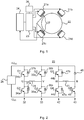
- Fig 1 illustrates schematically an electromagnetic bearing arrangement according to an embodiment of the invention.
- the electromagnetic bearing arrangement comprises four electromagnets 21a-d arranged e.g. equiangularly around a rotating equipment 22 such as a rotor of an electric machine.
- the rotating equipment 22 may be oriented such that its rotation axis is horizontal and the four electromagnets 21a-d may be arranged 45 degrees off the vertical and horizontal axis such that not a sole electromagnet will be responsible for counteracting the gravitational forces of the rotating equipment.
- the two electromagnets 21a-b may be referred to as upper electromagnets and the two electromagnets 21c-d may be referred to as lower electromagnets.
- electromagnetic bearing arrangement of the invention may comprise any number of electromagnets arranged in any suitable configuration.
- the electromagnetic bearing arrangement further comprises an amplifier arrangement 23 for operating the electromagnets 21a-d, a power supply 26 for supplying the amplifier arrangement 23 with power, and a controller 24 for controlling the amplifier arrangement 23 to operate the electromagnets 21a-d.
- the controller 24 may also be powered by the power supply 26.
- Sensors 27 such as position sensors may be provided for measuring the positions of the electromagnets 21a-d and for forwarding the measured positions to the controller 24, which controls the operation of the amplifier arrangement 23 and thus the electromagnets 21a-d in response thereto, thus providing feedback control.
- the amplifier arrangement 23 may comprise a first switching leg pair 32, 33 and a second switching leg pair 42, 43 as being illustrated in Fig. 2 .
- Each switching leg 32, 33 of the first pair has two switches 34a-b, 35a-b, and a coil 31 of a first electromagnet 21a is electrically connected to the junctions U and V between the switches 34a-b, 35a-b of each of the switching legs 32, 33 of the first pair.
- Each of switches 34a-b, 35a-b is provided with a diode 37a-b, 38a-b for bypassing the switch when the switch is in an off state.
- the switching leg 42 of the second pair has two switches 44a-b whereas the switching leg 43 has one switch 45 and one diode 48.
- a coil 41 of a second electromagnet 21d is electrically connected to the junctions W and B between the switches 44a-b of the switching leg 42 of the second pair and between the switch 45 and the diode 48 of the switching leg 43 of the second pair.
- Each of switches 44a-b of the switching leg 42 is provided with a diode 47a-b for bypassing the switch when the switch is in an off state.
- the power supply 26 is electrically connected to opposite ends of each of the switching legs 32, 33, 42, 43 of the first and second pair.
- Motor drives ACS M 1 and ACS 850 commercially available from ABB comprise the topology of the amplifier arrangement of Fig. 2 and may be used in this invention.
- the switches 34a-b, 35a-b, 44a-b, and 45 are controlled by the controller 24 via the control terminals G1-G6 and GB.
- the switches 34a-b, 35a-b, 44a-b, and 45 are IGBT's (Insulated-Gate Bipolar Transistors).
- controller 24 may be configured to control the amplifier arrangement of Fig. 2 to generate appropriate voltages over the first electromagnet 21a by using only two switches at a time: either switches 34a and 35b or switches 34b and 35a. This switching redundancy is not obtained in the right hand part of Fig. 2 . Therefore, the switch 44a and the diode 47b of the switch leg 42 may, in principle, be dispensed with. If the switch 44a is present, it should be kept in an off state during operation.
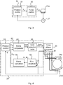
- Fig. 3 is a schematic illustration of a sensor and control structure implemented in the electromagnetic bearing arrangement of Fig. 1 .
- the controller 24 comprises a position control module 51, to which the position sensors 27 is operatively connected (only one of the position sensors 27 is shown in Fig. 3 ), such that the position control module 51 can determine force commands based on the measured positions of the electromagnets (only electromagnet 21a is shown) to provide the position based feedback control.
- the controller 24 comprises a direct force control module 52 which is configured to control the amplifier arrangement to operate the electromagnets 21a-d by switch commands determined based on the force commands and estimated forces exerted by the electromagnets.
- Fig. 4 illustrates schematically part of the electromagnetic bearing arrangement of Fig. 1 , wherein the controller 24 is further detailed. Note that only two 21a, 21d of the electromagnets 21a-d and only one of the amplifier arrangement 23 of Fig. 2 are shown in Fig. 4 .
- the position sensor 27 is operatively connected to the position control module 51 and the direct force control module 52 to forward the measured position S of the electromagnet 21a to these modules. Since the electromagnets 21a and 21d are arranged fixedly with respect to one another, the position of the rotating equipment in relation to the electromagnet 21a gives also the position of the rotating equipment in relation to the electromagnet 21d.
- the position control module 51 is configured to calculate a force reference F ref or force commands based on the measured position S of the electromagnets 21a and 21d.
- the electromagnetic bearing arrangement comprises a sensor arrangement 61 for measuring at least one parameter indicative of a force exerted by the electromagnets 21a and 21d and is operatively connected to the direct force control module 52 to forward the measured parameter indicative of the force exerted by the electromagnets 21a and 21d to the direct force control module 52.
- the sensor arrangement 61 may comprise one or more current sensors and/or one or more voltage sensors, and the at least one parameter indicative of a force exerted by the electromagnet 21a may comprise one or more currents and optionally voltages of the amplifier arrangement 23.
- the at least one parameter indicative of a force exerted by the electromagnets 21a and 21d comprises the currents i u and i d of the coils 31, 41 of the electromagnets 21a and 21d.
- the direct force control module 52 may be configured to calculate an estimated force F cal exerted by the electromagnets 21a and 21d based on the measured at least one parameter indicative of the force exerted by the electromagnets 21a and 21d, and the measured position S of the electromagnets 21a and 21d.
- the estimated force F cal is preferably the sum of the forces exerted by the electromagnets 21a and 21d.
- the direct force control module 52 is further configured to compare the force reference F ref with the estimated force F cal exerted by the electromagnets 21a and 21d, and to control the amplifier arrangement 23 to operate the electromagnet 21a and 21d by switch commands determined based on the comparison.
- the direct force control module 52 may comprise a flux observer submodule 62 configured to calculate a flux ⁇ u , ⁇ i of the electromagnets 21a and 21d based on the measured currents; and a force calculator submodule 63 configured to calculate the estimated force F cal exerted by the electromagnets 21a and 21d based on the flux of the electromagnets 21a and 21d.
- the direct force control module 52 may comprise a force comparator submodule 64 configured to compare the force reference F ref with the estimated force F cal exerted by the electromagnets 21a and 21d, and to provide a force status based on the comparison.
- a gate selection table submodule 65 is configured to provide the switch commands for the amplifier arrangement 23 based on the force status.
- the gate selection table submodule 65 may hold a table comprising force statuses, and for each force status, a switch command to be used, and wherein the gate selection table submodule 65 is configured to provide the switch commands for the amplifier arrangement 23 by referring to the table.
- F s is the force status
- F e is a predefined hysteresis force level depending on the particular application to be used.
- Table 1 One example of a table comprising force statuses, and for each force status, a switch command to be used as held by the gate selection table submodule 65 is given by Table 1.
- Table 1 Example table comprising force statuses, and for each force status, a switch command F s G 1 G 2 G 3 G 4 G 5 G6 GB + F DC 1 0 0 1 0 0 0 - F DC 0 0 0 0 1 0 1 0 0 0 0 1 0 0 1 0 1 0 0 1 0 0 1 0 0 1 0 1 0 0 1 0 0 1 0 0 1 0 0 1
Landscapes
- Engineering & Computer Science (AREA)
- General Engineering & Computer Science (AREA)
- Physics & Mathematics (AREA)
- Electromagnetism (AREA)
- Mechanical Engineering (AREA)
- Magnetic Bearings And Hydrostatic Bearings (AREA)
Priority Applications (4)
| Application Number | Priority Date | Filing Date | Title |
|---|---|---|---|
| EP14164597.8A EP2933512B1 (en) | 2014-04-14 | 2014-04-14 | Magnetic bearing arrangement and method of operating a magnetic bearing arrangement |
| PL14164597T PL2933512T3 (pl) | 2014-04-14 | 2014-04-14 | Układ łożyska magnetycznego i sposób działania układu łożyska magnetycznego |
| PCT/EP2015/056583 WO2015158520A1 (en) | 2014-04-14 | 2015-03-26 | Magnetic bearing arrangement and method of operating a magnetic bearing arrangement |
| US15/128,875 US9739308B2 (en) | 2014-04-14 | 2015-03-26 | Magnetic bearing arrangement and method of operating a magnetic bearing arrangement |
Applications Claiming Priority (1)
| Application Number | Priority Date | Filing Date | Title |
|---|---|---|---|
| EP14164597.8A EP2933512B1 (en) | 2014-04-14 | 2014-04-14 | Magnetic bearing arrangement and method of operating a magnetic bearing arrangement |
Publications (2)
| Publication Number | Publication Date |
|---|---|
| EP2933512A1 EP2933512A1 (en) | 2015-10-21 |
| EP2933512B1 true EP2933512B1 (en) | 2017-06-14 |
Family
ID=50478756
Family Applications (1)
| Application Number | Title | Priority Date | Filing Date |
|---|---|---|---|
| EP14164597.8A Active EP2933512B1 (en) | 2014-04-14 | 2014-04-14 | Magnetic bearing arrangement and method of operating a magnetic bearing arrangement |
Country Status (4)
| Country | Link |
|---|---|
| US (1) | US9739308B2 (pl) |
| EP (1) | EP2933512B1 (pl) |
| PL (1) | PL2933512T3 (pl) |
| WO (1) | WO2015158520A1 (pl) |
Families Citing this family (7)
| Publication number | Priority date | Publication date | Assignee | Title |
|---|---|---|---|---|
| DE102009051654B4 (de) | 2009-10-30 | 2013-01-03 | Eppendorf Ag | Dosiervorrichtung für Flüssigkeiten und Verfahren zum Dosieren von Flüssigkeiten |
| US10495145B2 (en) * | 2016-04-22 | 2019-12-03 | Ingersoll-Rand Company | Active magnetic bearing controller |
| EP3526479B1 (en) * | 2016-11-30 | 2021-02-24 | Synchrony, Inc. | Balanced switching amplifier for a magnetic bearing assembly |
| US10385665B2 (en) * | 2017-09-20 | 2019-08-20 | Upwing Energy, LLC | Axial gap generator measurement tool |
| CN108374840B (zh) * | 2018-03-30 | 2023-08-25 | 浙江师范大学 | 一种基于磁流变效应的滑动轴承制动装置及控制方法 |
| CN111894980B (zh) * | 2020-07-31 | 2022-02-18 | 苏州工业园区服务外包职业学院 | 一种磁悬浮轴承系统控制方法 |
| CN116539999B (zh) * | 2023-06-06 | 2025-11-04 | 华能核能技术研究院有限公司 | 主氦风机电磁轴承电磁铁电气参数的在线测量方法及装置 |
Family Cites Families (11)
| Publication number | Priority date | Publication date | Assignee | Title |
|---|---|---|---|---|
| US5666013A (en) * | 1992-12-07 | 1997-09-09 | Seiko Seiki Kabushiki Kaisha | Magnetic bearing |
| US6965181B1 (en) * | 1997-09-15 | 2005-11-15 | Mohawk Innovative Technology, Inc. | Hybrid foil-magnetic bearing with improved load sharing |
| US6078119A (en) * | 1997-11-26 | 2000-06-20 | Ebara Corporation | Bearingless rotary machine |
| JP2000145773A (ja) * | 1998-11-13 | 2000-05-26 | Nsk Ltd | 磁気軸受装置 |
| JP4036567B2 (ja) * | 1999-01-27 | 2008-01-23 | 株式会社荏原製作所 | 制御形磁気軸受装置 |
| JP3636939B2 (ja) * | 1999-07-15 | 2005-04-06 | オークマ株式会社 | 磁気軸受の制御装置 |
| JP2005006432A (ja) * | 2003-06-12 | 2005-01-06 | Koyo Seiko Co Ltd | 磁気軸受制御装置 |
| JP5025505B2 (ja) * | 2008-01-24 | 2012-09-12 | 株式会社荏原製作所 | 磁気軸受装置 |
| JP5316080B2 (ja) * | 2009-02-26 | 2013-10-16 | 株式会社明電舎 | モータ制御装置 |
| US8115358B1 (en) | 2009-03-18 | 2012-02-14 | Mikhail A Rakov | Method and systems for operating magnetic bearings and bearingless drives |
| CN104204569B (zh) | 2012-04-04 | 2017-08-25 | 开利公司 | 多轴磁轴承和对具有主动开关拓扑的磁轴承的控制 |
-
2014
- 2014-04-14 PL PL14164597T patent/PL2933512T3/pl unknown
- 2014-04-14 EP EP14164597.8A patent/EP2933512B1/en active Active
-
2015
- 2015-03-26 WO PCT/EP2015/056583 patent/WO2015158520A1/en not_active Ceased
- 2015-03-26 US US15/128,875 patent/US9739308B2/en active Active
Non-Patent Citations (1)
| Title |
|---|
| CLAUDIUS M ZINGERLI ET AL: "Novel observer based force control for active magnetic bearings", 2010 INTERNATIONAL POWER ELECTRONICS CONFERENCE : IPEC-SAPPORO 2010 - [ECCE ASIA] ; SAPPORO, JAPAN, IEEE, PISCATAWAY, NJ, USA, 21 June 2010 (2010-06-21), pages 2189 - 2196, XP031729711, ISBN: 978-1-4244-5394-8 * |
Also Published As
| Publication number | Publication date |
|---|---|
| US9739308B2 (en) | 2017-08-22 |
| US20170122372A1 (en) | 2017-05-04 |
| PL2933512T3 (pl) | 2017-11-30 |
| WO2015158520A1 (en) | 2015-10-22 |
| EP2933512A1 (en) | 2015-10-21 |
Similar Documents
| Publication | Publication Date | Title |
|---|---|---|
| EP2933512B1 (en) | Magnetic bearing arrangement and method of operating a magnetic bearing arrangement | |
| EP2808994B1 (en) | Active voltage controller for an electric motor | |
| US9673685B2 (en) | System and method for detection of motor vibration | |
| JP5316080B2 (ja) | モータ制御装置 | |
| US20190386588A1 (en) | Short-circuit braking of an llm | |
| JP7155531B2 (ja) | 磁気浮上制御装置および真空ポンプ | |
| CA2727467C (en) | Minimum temperature control for electromechanical actuator | |
| JP2016077140A (ja) | 高性能の動き制御のためのモーター・サーボ・ドライブ | |
| EP2869461A1 (en) | Motor controller | |
| KR100574265B1 (ko) | 엘리베이터의 제어 장치 | |
| US20150222210A1 (en) | Generating motor control reference signal with control voltage budget | |
| EP2514691B1 (en) | Control method for a conveyor belt | |
| JP2014110653A (ja) | 電磁回転装置及び該電磁回転装置を備えた真空ポンプ | |
| JP2010180974A (ja) | ベアリングレスモータのパラメータ設定方法 | |
| US6342772B1 (en) | Drive circuit and method for driving a switched reluctance machine | |
| US10630218B2 (en) | Motor control device | |
| JP2011120471A (ja) | モータ制御方法およびその装置 | |
| JP6265043B2 (ja) | 同期電動機のセンサレス駆動装置 | |
| CN106160595B (zh) | 用于运行电机的方法以及驱动器 | |
| KR20250092501A (ko) | 인버터 제어 장치 | |
| JPS60257790A (ja) | 交流エレベ−タの制御装置 | |
| Murthy et al. | Energy-optimal single-axis motion trajectories | |
| JP2019017218A (ja) | 同期電動機を駆動するインバータの制御装置および制御方法 | |
| Madhuri et al. | Performance analysis of Inverter fed Induction Motor with minimum settling time control | |
| US20070085509A1 (en) | Method for distributing current to the rectifier valves in inverting converters |
Legal Events
| Date | Code | Title | Description |
|---|---|---|---|
| PUAI | Public reference made under article 153(3) epc to a published international application that has entered the european phase |
Free format text: ORIGINAL CODE: 0009012 |
|
| AK | Designated contracting states |
Kind code of ref document: A1 Designated state(s): AL AT BE BG CH CY CZ DE DK EE ES FI FR GB GR HR HU IE IS IT LI LT LU LV MC MK MT NL NO PL PT RO RS SE SI SK SM TR |
|
| AX | Request for extension of the european patent |
Extension state: BA ME |
|
| 17P | Request for examination filed |
Effective date: 20160421 |
|
| RBV | Designated contracting states (corrected) |
Designated state(s): AL AT BE BG CH CY CZ DE DK EE ES FI FR GB GR HR HU IE IS IT LI LT LU LV MC MK MT NL NO PL PT RO RS SE SI SK SM TR |
|
| GRAP | Despatch of communication of intention to grant a patent |
Free format text: ORIGINAL CODE: EPIDOSNIGR1 |
|
| TPAC | Observations filed by third parties |
Free format text: ORIGINAL CODE: EPIDOSNTIPA |
|
| INTG | Intention to grant announced |
Effective date: 20160607 |
|
| 17Q | First examination report despatched |
Effective date: 20160722 |
|
| GRAS | Grant fee paid |
Free format text: ORIGINAL CODE: EPIDOSNIGR3 |
|
| RAP1 | Party data changed (applicant data changed or rights of an application transferred) |
Owner name: ABB SCHWEIZ AG |
|
| GRAJ | Information related to disapproval of communication of intention to grant by the applicant or resumption of examination proceedings by the epo deleted |
Free format text: ORIGINAL CODE: EPIDOSDIGR1 |
|
| GRAJ | Information related to disapproval of communication of intention to grant by the applicant or resumption of examination proceedings by the epo deleted |
Free format text: ORIGINAL CODE: EPIDOSDIGR1 |
|
| GRAP | Despatch of communication of intention to grant a patent |
Free format text: ORIGINAL CODE: EPIDOSNIGR1 |
|
| GRAS | Grant fee paid |
Free format text: ORIGINAL CODE: EPIDOSNIGR3 |
|
| GRAP | Despatch of communication of intention to grant a patent |
Free format text: ORIGINAL CODE: EPIDOSNIGR1 |
|
| INTC | Intention to grant announced (deleted) | ||
| INTG | Intention to grant announced |
Effective date: 20170330 |
|
| GRAA | (expected) grant |
Free format text: ORIGINAL CODE: 0009210 |
|
| AK | Designated contracting states |
Kind code of ref document: B1 Designated state(s): AL AT BE BG CH CY CZ DE DK EE ES FI FR GB GR HR HU IE IS IT LI LT LU LV MC MK MT NL NO PL PT RO RS SE SI SK SM TR |
|
| REG | Reference to a national code |
Ref country code: GB Ref legal event code: FG4D |
|
| REG | Reference to a national code |
Ref country code: CH Ref legal event code: EP Ref country code: AT Ref legal event code: REF Ref document number: 901279 Country of ref document: AT Kind code of ref document: T Effective date: 20170615 |
|
| REG | Reference to a national code |
Ref country code: IE Ref legal event code: FG4D |
|
| REG | Reference to a national code |
Ref country code: DE Ref legal event code: R096 Ref document number: 602014010664 Country of ref document: DE |
|
| REG | Reference to a national code |
Ref country code: NL Ref legal event code: FP |
|
| REG | Reference to a national code |
Ref country code: LT Ref legal event code: MG4D |
|
| PG25 | Lapsed in a contracting state [announced via postgrant information from national office to epo] |
Ref country code: HR Free format text: LAPSE BECAUSE OF FAILURE TO SUBMIT A TRANSLATION OF THE DESCRIPTION OR TO PAY THE FEE WITHIN THE PRESCRIBED TIME-LIMIT Effective date: 20170614 Ref country code: NO Free format text: LAPSE BECAUSE OF FAILURE TO SUBMIT A TRANSLATION OF THE DESCRIPTION OR TO PAY THE FEE WITHIN THE PRESCRIBED TIME-LIMIT Effective date: 20170914 Ref country code: GR Free format text: LAPSE BECAUSE OF FAILURE TO SUBMIT A TRANSLATION OF THE DESCRIPTION OR TO PAY THE FEE WITHIN THE PRESCRIBED TIME-LIMIT Effective date: 20170915 Ref country code: LT Free format text: LAPSE BECAUSE OF FAILURE TO SUBMIT A TRANSLATION OF THE DESCRIPTION OR TO PAY THE FEE WITHIN THE PRESCRIBED TIME-LIMIT Effective date: 20170614 |
|
| REG | Reference to a national code |
Ref country code: AT Ref legal event code: MK05 Ref document number: 901279 Country of ref document: AT Kind code of ref document: T Effective date: 20170614 |
|
| PG25 | Lapsed in a contracting state [announced via postgrant information from national office to epo] |
Ref country code: LV Free format text: LAPSE BECAUSE OF FAILURE TO SUBMIT A TRANSLATION OF THE DESCRIPTION OR TO PAY THE FEE WITHIN THE PRESCRIBED TIME-LIMIT Effective date: 20170614 Ref country code: RS Free format text: LAPSE BECAUSE OF FAILURE TO SUBMIT A TRANSLATION OF THE DESCRIPTION OR TO PAY THE FEE WITHIN THE PRESCRIBED TIME-LIMIT Effective date: 20170614 Ref country code: SE Free format text: LAPSE BECAUSE OF FAILURE TO SUBMIT A TRANSLATION OF THE DESCRIPTION OR TO PAY THE FEE WITHIN THE PRESCRIBED TIME-LIMIT Effective date: 20170614 Ref country code: BG Free format text: LAPSE BECAUSE OF FAILURE TO SUBMIT A TRANSLATION OF THE DESCRIPTION OR TO PAY THE FEE WITHIN THE PRESCRIBED TIME-LIMIT Effective date: 20170914 |
|
| PG25 | Lapsed in a contracting state [announced via postgrant information from national office to epo] |
Ref country code: RO Free format text: LAPSE BECAUSE OF FAILURE TO SUBMIT A TRANSLATION OF THE DESCRIPTION OR TO PAY THE FEE WITHIN THE PRESCRIBED TIME-LIMIT Effective date: 20170614 Ref country code: SK Free format text: LAPSE BECAUSE OF FAILURE TO SUBMIT A TRANSLATION OF THE DESCRIPTION OR TO PAY THE FEE WITHIN THE PRESCRIBED TIME-LIMIT Effective date: 20170614 Ref country code: EE Free format text: LAPSE BECAUSE OF FAILURE TO SUBMIT A TRANSLATION OF THE DESCRIPTION OR TO PAY THE FEE WITHIN THE PRESCRIBED TIME-LIMIT Effective date: 20170614 Ref country code: CZ Free format text: LAPSE BECAUSE OF FAILURE TO SUBMIT A TRANSLATION OF THE DESCRIPTION OR TO PAY THE FEE WITHIN THE PRESCRIBED TIME-LIMIT Effective date: 20170614 Ref country code: AT Free format text: LAPSE BECAUSE OF FAILURE TO SUBMIT A TRANSLATION OF THE DESCRIPTION OR TO PAY THE FEE WITHIN THE PRESCRIBED TIME-LIMIT Effective date: 20170614 |
|
| PG25 | Lapsed in a contracting state [announced via postgrant information from national office to epo] |
Ref country code: ES Free format text: LAPSE BECAUSE OF FAILURE TO SUBMIT A TRANSLATION OF THE DESCRIPTION OR TO PAY THE FEE WITHIN THE PRESCRIBED TIME-LIMIT Effective date: 20170614 Ref country code: SM Free format text: LAPSE BECAUSE OF FAILURE TO SUBMIT A TRANSLATION OF THE DESCRIPTION OR TO PAY THE FEE WITHIN THE PRESCRIBED TIME-LIMIT Effective date: 20170614 Ref country code: IS Free format text: LAPSE BECAUSE OF FAILURE TO SUBMIT A TRANSLATION OF THE DESCRIPTION OR TO PAY THE FEE WITHIN THE PRESCRIBED TIME-LIMIT Effective date: 20171014 |
|
| REG | Reference to a national code |
Ref country code: DE Ref legal event code: R097 Ref document number: 602014010664 Country of ref document: DE |
|
| PLBE | No opposition filed within time limit |
Free format text: ORIGINAL CODE: 0009261 |
|
| REG | Reference to a national code |
Ref country code: FR Ref legal event code: PLFP Year of fee payment: 5 |
|
| STAA | Information on the status of an ep patent application or granted ep patent |
Free format text: STATUS: NO OPPOSITION FILED WITHIN TIME LIMIT |
|
| PG25 | Lapsed in a contracting state [announced via postgrant information from national office to epo] |
Ref country code: DK Free format text: LAPSE BECAUSE OF FAILURE TO SUBMIT A TRANSLATION OF THE DESCRIPTION OR TO PAY THE FEE WITHIN THE PRESCRIBED TIME-LIMIT Effective date: 20170614 |
|
| 26N | No opposition filed |
Effective date: 20180315 |
|
| PG25 | Lapsed in a contracting state [announced via postgrant information from national office to epo] |
Ref country code: SI Free format text: LAPSE BECAUSE OF FAILURE TO SUBMIT A TRANSLATION OF THE DESCRIPTION OR TO PAY THE FEE WITHIN THE PRESCRIBED TIME-LIMIT Effective date: 20170614 |
|
| PG25 | Lapsed in a contracting state [announced via postgrant information from national office to epo] |
Ref country code: MC Free format text: LAPSE BECAUSE OF FAILURE TO SUBMIT A TRANSLATION OF THE DESCRIPTION OR TO PAY THE FEE WITHIN THE PRESCRIBED TIME-LIMIT Effective date: 20170614 |
|
| REG | Reference to a national code |
Ref country code: CH Ref legal event code: PL |
|
| REG | Reference to a national code |
Ref country code: BE Ref legal event code: MM Effective date: 20180430 |
|
| REG | Reference to a national code |
Ref country code: IE Ref legal event code: MM4A |
|
| PG25 | Lapsed in a contracting state [announced via postgrant information from national office to epo] |
Ref country code: LU Free format text: LAPSE BECAUSE OF NON-PAYMENT OF DUE FEES Effective date: 20180414 |
|
| PG25 | Lapsed in a contracting state [announced via postgrant information from national office to epo] |
Ref country code: LI Free format text: LAPSE BECAUSE OF NON-PAYMENT OF DUE FEES Effective date: 20180430 Ref country code: CH Free format text: LAPSE BECAUSE OF NON-PAYMENT OF DUE FEES Effective date: 20180430 Ref country code: BE Free format text: LAPSE BECAUSE OF NON-PAYMENT OF DUE FEES Effective date: 20180430 |
|
| PG25 | Lapsed in a contracting state [announced via postgrant information from national office to epo] |
Ref country code: IE Free format text: LAPSE BECAUSE OF NON-PAYMENT OF DUE FEES Effective date: 20180414 |
|
| PG25 | Lapsed in a contracting state [announced via postgrant information from national office to epo] |
Ref country code: MT Free format text: LAPSE BECAUSE OF NON-PAYMENT OF DUE FEES Effective date: 20180414 |
|
| PG25 | Lapsed in a contracting state [announced via postgrant information from national office to epo] |
Ref country code: TR Free format text: LAPSE BECAUSE OF FAILURE TO SUBMIT A TRANSLATION OF THE DESCRIPTION OR TO PAY THE FEE WITHIN THE PRESCRIBED TIME-LIMIT Effective date: 20170614 |
|
| PG25 | Lapsed in a contracting state [announced via postgrant information from national office to epo] |
Ref country code: PT Free format text: LAPSE BECAUSE OF FAILURE TO SUBMIT A TRANSLATION OF THE DESCRIPTION OR TO PAY THE FEE WITHIN THE PRESCRIBED TIME-LIMIT Effective date: 20170614 |
|
| PG25 | Lapsed in a contracting state [announced via postgrant information from national office to epo] |
Ref country code: CY Free format text: LAPSE BECAUSE OF FAILURE TO SUBMIT A TRANSLATION OF THE DESCRIPTION OR TO PAY THE FEE WITHIN THE PRESCRIBED TIME-LIMIT Effective date: 20170614 Ref country code: HU Free format text: LAPSE BECAUSE OF FAILURE TO SUBMIT A TRANSLATION OF THE DESCRIPTION OR TO PAY THE FEE WITHIN THE PRESCRIBED TIME-LIMIT; INVALID AB INITIO Effective date: 20140414 Ref country code: MK Free format text: LAPSE BECAUSE OF NON-PAYMENT OF DUE FEES Effective date: 20170614 |
|
| PG25 | Lapsed in a contracting state [announced via postgrant information from national office to epo] |
Ref country code: AL Free format text: LAPSE BECAUSE OF FAILURE TO SUBMIT A TRANSLATION OF THE DESCRIPTION OR TO PAY THE FEE WITHIN THE PRESCRIBED TIME-LIMIT Effective date: 20170614 |
|
| PGFP | Annual fee paid to national office [announced via postgrant information from national office to epo] |
Ref country code: NL Payment date: 20250418 Year of fee payment: 12 |
|
| PGFP | Annual fee paid to national office [announced via postgrant information from national office to epo] |
Ref country code: FI Payment date: 20250424 Year of fee payment: 12 |
|
| PGFP | Annual fee paid to national office [announced via postgrant information from national office to epo] |
Ref country code: PL Payment date: 20250403 Year of fee payment: 12 Ref country code: DE Payment date: 20250422 Year of fee payment: 12 |
|
| PGFP | Annual fee paid to national office [announced via postgrant information from national office to epo] |
Ref country code: GB Payment date: 20250423 Year of fee payment: 12 |
|
| PGFP | Annual fee paid to national office [announced via postgrant information from national office to epo] |
Ref country code: IT Payment date: 20250424 Year of fee payment: 12 |
|
| PGFP | Annual fee paid to national office [announced via postgrant information from national office to epo] |
Ref country code: FR Payment date: 20250425 Year of fee payment: 12 |