EP2933403A1 - Dispositif d'armature pour un vantail d'une porte - Google Patents
Dispositif d'armature pour un vantail d'une porte Download PDFInfo
- Publication number
- EP2933403A1 EP2933403A1 EP15162686.8A EP15162686A EP2933403A1 EP 2933403 A1 EP2933403 A1 EP 2933403A1 EP 15162686 A EP15162686 A EP 15162686A EP 2933403 A1 EP2933403 A1 EP 2933403A1
- Authority
- EP
- European Patent Office
- Prior art keywords
- rosette
- end portions
- fitting device
- fitting
- door leaf
- Prior art date
- Legal status (The legal status is an assumption and is not a legal conclusion. Google has not performed a legal analysis and makes no representation as to the accuracy of the status listed.)
- Withdrawn
Links
Images


Classifications
-
- E—FIXED CONSTRUCTIONS
- E05—LOCKS; KEYS; WINDOW OR DOOR FITTINGS; SAFES
- E05B—LOCKS; ACCESSORIES THEREFOR; HANDCUFFS
- E05B15/00—Other details of locks; Parts for engagement by bolts of fastening devices
- E05B15/02—Striking-plates; Keepers; Bolt staples; Escutcheons
Definitions
- fittings in the form of fitting devices.
- This is to be understood as the covering of openings for lock cylinders or the covering of passages for handles for opening and closing the door.
- Known fitting devices are usually formed on both sides of the door leaf, each with a rosette body, which on the one hand fulfills decorative functions, on the other hand brings a protective function with it.
- rosette body are contacted either attaching to the handle or with the lock cylinder.
- An attachment directly in the door leaf is also conceivable.
- a disadvantage of the known fitting devices and also in known rosette bodies is that they have only a low resistance to vandalism due to their decorative character.
- a multi-part embodiment is necessary in known fitting devices.
- mechanically reinforcing protective elements are used behind the respective rosette body to ensure greater resistance.
- this also leads to a more complex and costly installation of the entire fitting device.
- a fitting device according to the invention for a door leaf of a door has at least two rosette bodies for installation on two different sides of the door leaf.
- a fitting device according to the invention is characterized in that a connecting device extends between the two rosette bodies for a torsion reinforcement.
- the connecting device has at least two end portions, which are fastened to the respective rosette body. In this case, at least one of the end portions overlaps with a connecting portion of a rosette body.
- the torsional reinforcement and thus the increased resistance to vandalism is no longer ensured by the rosette body, but by the connecting device.
- the rosette body itself can be formed in one piece and in particular be focused in a cost effective and simple manner on the decorative character of their functionality.
- a connecting device is to be understood in the sense of the present invention in that it produces a force-transmitting connection between the two rosette bodies.
- this force can be supported on the other rosette body via the connecting device on the other side of the door leaf.
- the connecting device on the mentioned end portions which already ensure a power transmission possibility between the two rosette bodies by the attachment.
- a connecting section is provided for the respective end section of the connecting device.
- the connecting portion has a function that results in the assembly of the fitting device to an overlap with the respective end portion of the connecting device. If, for example, the individual components of the connecting device extend axially between the two rosette bodies, an overlap occurs between the connecting section and the end section over an axial length.
- the connecting device is also applied off-center, so that the torsion reinforcement allows not only a pure axial force transmission, but also against twisting a torque transmission between the two rosette bodies.
- the overlapping between the end portion of the connecting device and the connecting portion of the respective rosette body results in that a relatively large area is provided to initiate the respective force from the rosette body in the connecting device.
- This undesirable plastic deformation of the connecting device and / or the rosette body can be avoided with high probability.
- the necessary deformation force, and in particular the force required to forcibly remove the rosette body from the side of the door panel thereby increases significantly.
- no additional effort must be made in the rosette body for this mechanical resistance. Rather, the function of mechanical resistance is transferred to the connecting device, so that simple, cost-effective and especially with regard to the design function optimized rosette body can continue to be used. It is preferred if even existing constructions of rosette bodies can be used, wherein the connection sections are additionally formed on the rear side thereof.
- Another advantage of the present invention is that, in a known manner, the assembly can take place simply, quickly and inexpensively.
- the connecting device extends through the door leaf from one side to the other side. Thus, for example, by additional holes or already an existing hole or opening in the door leaf, a guide of the connecting device between the two rosette bodies can be ensured.
- the connecting device can bring about the increase in the resistance in addition to the overlap with the connecting portion in the end portions also via a torsion resistance in cross section with it.
- the cross-section of the connection device may have a high resistance value, so that a torsion of the connection device is provided with high force resistance.
- the actual alignment in the axial direction between the two rosette bodies leads to a mechanical stabilization effect by the connecting device.
- this can be carried out on both sides.
- the end portion is disposed respectively within the connection portion, or conversely, the end portion overlaps outside the connection portion.
- a double overlap inside and outside in both directions is conceivable within the meaning of the present invention.
- an overlap of more than about 3 mm and less than about 5 mm is advantageous. Within these limits, a sufficient connection stiffening can be achieved without having to take unnecessary influence on the geometry of the door leaf.
- the connecting device has two connecting elements, in particular with a round or substantially round cross section.
- the two connecting elements are laterally spaced from each other and each extending between the two rosette bodies, wherein they are each secured with their end portions on the corresponding rosette body.
- three or more connecting elements may be provided for the connecting device.
- fastening means a reversible or irreversible attachment.
- an attachment can be made with screw means, as will be explained in more detail later.
- screw means for example, an internal thread can be used, in which from the outside of the respective rosette body for fastening a screw is screwed.
- the individual connecting elements can be formed from solid material or from a hollow material. It is preferred if the connecting elements are designed with round or square cross-section than inside hollow sleeves, to allow a particularly simple and cost-effective production.
- the connecting device in particular the connecting elements of the connecting device, have a thread at their end sections and / or in the region of their end sections, in particular an internal thread.
- a corresponding fastening function can be achieved.
- the thread is in particular a standard thread, preferably a metric standard thread.
- a screw means which is designed, for example, as a screw with a screw head, has a screw interface in order to introduce the necessary tightening torque into the screw means.
- a deviation from the circular shape is an advantage.
- deviating from standard screw interfaces an increased protection against unwanted removal is given.
- similar to a rim lock a unique and specific contour for the screw interface can be made available.
- unusual standard screw interfaces such as a Torx interface, for example, in which additional contour sections, for example in the form of a security pin, enable this increased security functionality.
- a fitting device in a fitting device according to the invention at least one rosette body has a receiving opening with a guide arranged therein for a handle, wherein a securing device is provided against axial withdrawal of the handle from the guide.
- a fitting device according to the invention for covering the sides of a lock cylinder, such a fitting device can be designed completely or at least in sections also for the lateral covering of a handle in the form of a door handle. In this case, this handle extends in sections into a corresponding receptacle of the rosette body.
- a guide which may also be designed as a guide bush, is used for introducing and securing the handle.
- the security device now serves to provide additional resistance to vandalism. So not only a lateral mechanical action on the rosette body, but also a strong pulling on the handle for Cause destruction or damage.
- the safety device now prevents axial withdrawal of the handle and thus allows an increased safety function even with vandalism.
- a fitting device can be further developed such that the guide is fastened to the rosette body via a fastening section, in particular by cold forming.
- the securing device has a counter ring, which is attached to the guide, in particular by pressing, and covers the attachment portion at least partially contacting.
- cold forming in the form of a crimping process can be used. In terms of functionality, this means that when pulling out or attempting to pull out the handle this mating ring plastically deformed and thus blocks further withdrawal. This can cost-effective and easy backup against vandalism in a fitting device according to the invention can be further improved.
- At least one of the end sections, which are formed in a contact-overlapping manner with the respective connecting section has a surface structure that improves the friction.
- a knurling may be provided, so that when introducing the end portion in the overlapping position with the connecting portion has a higher friction, so that when screwing from the outside co-rotation of the end portion and thus the respective connecting element is avoided with high probability. This is no longer necessary to counteract, so that at completely concealed position of the connecting device a screw mounting is possible.
- a fitting device according to the invention brings the same advantages, as will be explained in more detail below.
- a rosette body for a fitting device in particular according to the present invention, for a door leaf of a door, comprising a base body with a contact portion for abutment with the door leaf and a decor portion, which is visible in abutting the door leaf contact portion.
- a rosette body according to the invention is characterized in that the contact section and the decorative section are formed integrally with the main body.
- a rosette body according to the invention can be further developed such that the base body has a minimum wall thickness which is ⁇ 2 mm. It is a range of about 2 mm, in particular, the minimum wall thickness ⁇ 10 mm, preferably ⁇ 5 mm, is formed. In particular, the minimum wall thickness is in the range between about 2 mm and about 3 mm. This represents an optimum in terms of easy and inexpensive manufacturability and increases the strength function according to the present invention.
- the base body is designed as a precision casting workpiece.
- stainless steel or another high-quality material can be used, and by possible post-processing of the decorative section a desired high-quality surface can be achieved.
- Such post-processing steps may be, for example, milling steps, grinding steps and / or polishing steps.
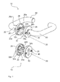
- the Fig. 1 and 4 show first embodiments of fitting devices 10. These are the same for both the cover of a cylinder lock, as well as for the covering of a handle 60 on both sides of the door leaf.
- two rosette bodies 20 are provided, which are designed to rest on two different sides of a door leaf.
- These rosette bodies 20 are equipped with a main body 26, which has an outwardly directed decor section 26b and an inwardly directed abutment section 26a.
- a connecting device 30 is provided here for both fitting devices 10.
- This connecting device 30 has in each case two connecting elements 34a and 34b.
- Each of these connecting elements 34a and 34b which are laterally spaced apart, has an end portion 32a at the first end and an end portion 32b at the second end. All end portions 32a and 32b are in overlapping manner within connecting portions 22a and 22b of the two rosette bodies 20. If a mechanical interference from the outside of the rosette body 20 occurs in assembled manner, the applied force can be applied to the two via the individual connecting members 34a and 34b Rosette body 20 are distributed, and in particular be supported on the door leaf. Thus, the described invention increase the resistance can be ensured.
- Fig. 1 and the Fig. 4 can be further seen, an attachment of the individual fasteners 34a and 34b by screw means 40 from the outside of the rosette body 20 can take place.
- the two connecting elements 34a and 34b each have a thread 36 in the form of an internal thread into which the screw means 40 can be screwed.
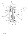
- Fig. 2 an alternative solution of the fitting devices 10 is shown, which differs from the embodiment of the Fig. 1 and 4 distinguished by the geometric design of the rosette body 20.
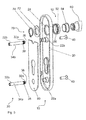
- Fig. 3 and 5 moreover, show a solution in which the fitting device 10 can be used for a cylinder lock, as well as for the handle 60 in a common manner.
- a backup plate 80 is inserted, which is able to provide protection against drilling. Again, however, the same increase in the resistance is given in accordance with the invention.
- Fig. 6 is a variation of the solution Fig. 1 and 4 shown in which the handle 60 is designed only on the right side for opening and closing the door.
- the handle 60 on the left side is a non-openable knob in this embodiment.
- the Fig. 7 shows a possibility of a screw 40 with a screw 42 with a locking pin, which avoids that an unwanted, unauthorized dismantling of the fitting device 10 is possible.
- Fig. 8 shows in schematic cross section a backup option of the handle 60, as in the embodiment of the Fig. 5 can be seen.
- the handle 60 is inserted into a guide 50, which is formed here by a receiving socket 52 and a guide bushing 54.
- the receiving socket 52 extends into the rosette body 20 inserted, so that on the opposite side of the securing device 70 can be attached with a retaining ring 74 and a counter-ring 72. In the axial tensile test, this leads to the deformation of the counter-ring 72 and thus by this plastic deformation to a backup against this axial tensile test.
Landscapes
- Lock And Its Accessories (AREA)
- Mutual Connection Of Rods And Tubes (AREA)
- Securing Of Glass Panes Or The Like (AREA)
Applications Claiming Priority (1)
| Application Number | Priority Date | Filing Date | Title |
|---|---|---|---|
| DE102014105333.8A DE102014105333A1 (de) | 2014-04-15 | 2014-04-15 | Beschlagvorrichtung für ein Türblatt einer Tür |
Publications (1)
| Publication Number | Publication Date |
|---|---|
| EP2933403A1 true EP2933403A1 (fr) | 2015-10-21 |
Family
ID=52813994
Family Applications (1)
| Application Number | Title | Priority Date | Filing Date |
|---|---|---|---|
| EP15162686.8A Withdrawn EP2933403A1 (fr) | 2014-04-15 | 2015-04-07 | Dispositif d'armature pour un vantail d'une porte |
Country Status (3)
| Country | Link |
|---|---|
| EP (1) | EP2933403A1 (fr) |
| CN (1) | CN105041041A (fr) |
| DE (1) | DE102014105333A1 (fr) |
Families Citing this family (1)
| Publication number | Priority date | Publication date | Assignee | Title |
|---|---|---|---|---|
| DE102022104487A1 (de) | 2022-02-24 | 2023-08-24 | Hermat-Metallwaren B. Porst GmbH | Rosettenanordnung zur Befestigung an einem Fenster oder einer Tür, Drückergarnitur mit Rosettenanordnung und Tür oder Fenster mit Drückergarnitur |
Citations (9)
| Publication number | Priority date | Publication date | Assignee | Title |
|---|---|---|---|---|
| DE29723740U1 (de) * | 1997-11-13 | 1999-01-07 | Evva Werke | Schutzbeschlag mit einem Schließzylinder |
| US20040100105A1 (en) * | 2002-11-25 | 2004-05-27 | Shen Mu-Lin | Cylindrical lock with improved resistance to torque |
| EP1455035A2 (fr) * | 2003-03-07 | 2004-09-08 | Zamet S.R.L. | Dispositif de couverture et mécanisme pour poignées de porte |
| DE202007014563U1 (de) * | 2007-10-16 | 2007-12-13 | Franz Schneider Brakel Gmbh & Co. Kg | Tür- oder Fensterbeschlag |
| DE202009008754U1 (de) * | 2009-06-24 | 2009-12-03 | Frascio Deutschland Gmbh | Rosettenanordnung |
| DE202009005997U1 (de) * | 2009-04-24 | 2011-06-28 | HOPPE AG, Bozen | Rosettenanordnung |
| WO2011079972A1 (fr) * | 2009-12-30 | 2011-07-07 | Franz Schneider Brakel Gmbh & Co. Kg | Armature pour portes ou fenêtres |
| GB2488002A (en) * | 2010-12-10 | 2012-08-15 | Hoppe Uk Ltd | A back plate with at least one fixing sleeve |
| EP2682543A2 (fr) * | 2012-07-05 | 2014-01-08 | HEWI Heinrich Wilke GmbH | Agencement d'armatures |
-
2014
- 2014-04-15 DE DE102014105333.8A patent/DE102014105333A1/de active Pending
-
2015
- 2015-04-07 EP EP15162686.8A patent/EP2933403A1/fr not_active Withdrawn
- 2015-04-14 CN CN201510176787.1A patent/CN105041041A/zh active Pending
Patent Citations (9)
| Publication number | Priority date | Publication date | Assignee | Title |
|---|---|---|---|---|
| DE29723740U1 (de) * | 1997-11-13 | 1999-01-07 | Evva Werke | Schutzbeschlag mit einem Schließzylinder |
| US20040100105A1 (en) * | 2002-11-25 | 2004-05-27 | Shen Mu-Lin | Cylindrical lock with improved resistance to torque |
| EP1455035A2 (fr) * | 2003-03-07 | 2004-09-08 | Zamet S.R.L. | Dispositif de couverture et mécanisme pour poignées de porte |
| DE202007014563U1 (de) * | 2007-10-16 | 2007-12-13 | Franz Schneider Brakel Gmbh & Co. Kg | Tür- oder Fensterbeschlag |
| DE202009005997U1 (de) * | 2009-04-24 | 2011-06-28 | HOPPE AG, Bozen | Rosettenanordnung |
| DE202009008754U1 (de) * | 2009-06-24 | 2009-12-03 | Frascio Deutschland Gmbh | Rosettenanordnung |
| WO2011079972A1 (fr) * | 2009-12-30 | 2011-07-07 | Franz Schneider Brakel Gmbh & Co. Kg | Armature pour portes ou fenêtres |
| GB2488002A (en) * | 2010-12-10 | 2012-08-15 | Hoppe Uk Ltd | A back plate with at least one fixing sleeve |
| EP2682543A2 (fr) * | 2012-07-05 | 2014-01-08 | HEWI Heinrich Wilke GmbH | Agencement d'armatures |
Also Published As
| Publication number | Publication date |
|---|---|
| DE102014105333A1 (de) | 2015-10-15 |
| CN105041041A (zh) | 2015-11-11 |
Similar Documents
| Publication | Publication Date | Title |
|---|---|---|
| EP2147221B1 (fr) | Élément de vissage à sécurité antivol | |
| DE69909218T2 (de) | Türfallenanschlag | |
| EP1961976B1 (fr) | Dispositif de fixation | |
| EP3025066B1 (fr) | Écrou à sertir en aveugle pour le raccordement de deux éléments | |
| DE102013109036A1 (de) | Verfahren zum Verbinden von Bauteilen sowie Baugruppe | |
| WO2002038897A1 (fr) | Douille pour fixer un element de ferrures sur un profile creux pourvu d'une partie profilee saillante | |
| DE102007036554B4 (de) | Deckel-Lager-Anordnung und Verfahren zum Montieren einer Aktuatorwelle | |
| DE202007003675U1 (de) | Vorrichtung zur Befestigung von Beschlagteilen an Hohlprofilen | |
| EP2265785B1 (fr) | Charnière pour une fenêtre ou une porte | |
| EP2565351B1 (fr) | Agencement de poignée | |
| EP3205794A1 (fr) | Système de poignée et procédé de montage | |
| DE102008001381B3 (de) | Baueinheit | |
| EP2933403A1 (fr) | Dispositif d'armature pour un vantail d'une porte | |
| DE102007029448A1 (de) | Werkzeug | |
| EP2141310B1 (fr) | Raccord de montage doté d'un élément de ressort pour poignée | |
| EP3363969A1 (fr) | Poignée d'actionnement | |
| DE102015012641B3 (de) | Gelenkverbindung | |
| WO2014048989A1 (fr) | Vis de montage destinée à la fixation de ferrures sur des profilés creux, kit de vis de montage et agencement constitué d'un profilé à plusieurs chambres et d'une vis de montage | |
| DE60107178T2 (de) | Elastisches Gelenk für einen Stossdämpfer and Stossdämpfer mit einem solchen Gelenk | |
| EP2581536A2 (fr) | Palier d'angle | |
| DE102011112049B4 (de) | Gurtschlossbaugruppe | |
| EP1808562A2 (fr) | Charnière pour fenêtres ou portes tout comme procédé destiné à l'installation d'un pivot de charnière nécessaire au réglage dans une tête de charnière | |
| EP3808927A1 (fr) | Agencement doté de cadre et d'un battant appliqué au cadre à l'aide de charnières | |
| DE102016103877B4 (de) | Motorlagerschild | |
| DE102006041076A1 (de) | Getriebeanordnung mit axialer Sicherung |
Legal Events
| Date | Code | Title | Description |
|---|---|---|---|
| PUAI | Public reference made under article 153(3) epc to a published international application that has entered the european phase |
Free format text: ORIGINAL CODE: 0009012 |
|
| AK | Designated contracting states |
Kind code of ref document: A1 Designated state(s): AL AT BE BG CH CY CZ DE DK EE ES FI FR GB GR HR HU IE IS IT LI LT LU LV MC MK MT NL NO PL PT RO RS SE SI SK SM TR |
|
| AX | Request for extension of the european patent |
Extension state: BA ME |
|
| 17P | Request for examination filed |
Effective date: 20160404 |
|
| RBV | Designated contracting states (corrected) |
Designated state(s): AL AT BE BG CH CY CZ DE DK EE ES FI FR GB GR HR HU IE IS IT LI LT LU LV MC MK MT NL NO PL PT RO RS SE SI SK SM TR |
|
| STAA | Information on the status of an ep patent application or granted ep patent |
Free format text: STATUS: THE APPLICATION IS DEEMED TO BE WITHDRAWN |
|
| 18D | Application deemed to be withdrawn |
Effective date: 20160702 |