EP2929971A1 - Funkenerosionsmaschine mit drehtisch - Google Patents
Funkenerosionsmaschine mit drehtisch Download PDFInfo
- Publication number
- EP2929971A1 EP2929971A1 EP15160862.7A EP15160862A EP2929971A1 EP 2929971 A1 EP2929971 A1 EP 2929971A1 EP 15160862 A EP15160862 A EP 15160862A EP 2929971 A1 EP2929971 A1 EP 2929971A1
- Authority
- EP
- European Patent Office
- Prior art keywords
- power unit
- face plate
- speed reducer
- rotary table
- shaft
- Prior art date
- Legal status (The legal status is an assumption and is not a legal conclusion. Google has not performed a legal analysis and makes no representation as to the accuracy of the status listed.)
- Granted
Links
Images


Classifications
-
- B—PERFORMING OPERATIONS; TRANSPORTING
- B23—MACHINE TOOLS; METAL-WORKING NOT OTHERWISE PROVIDED FOR
- B23H—WORKING OF METAL BY THE ACTION OF A HIGH CONCENTRATION OF ELECTRIC CURRENT ON A WORKPIECE USING AN ELECTRODE WHICH TAKES THE PLACE OF A TOOL; SUCH WORKING COMBINED WITH OTHER FORMS OF WORKING OF METAL
- B23H11/00—Auxiliary apparatus or details, not otherwise provided for
- B23H11/003—Mounting of workpieces, e.g. working-tables
-
- B—PERFORMING OPERATIONS; TRANSPORTING
- B23—MACHINE TOOLS; METAL-WORKING NOT OTHERWISE PROVIDED FOR
- B23H—WORKING OF METAL BY THE ACTION OF A HIGH CONCENTRATION OF ELECTRIC CURRENT ON A WORKPIECE USING AN ELECTRODE WHICH TAKES THE PLACE OF A TOOL; SUCH WORKING COMBINED WITH OTHER FORMS OF WORKING OF METAL
- B23H1/00—Electrical discharge machining, i.e. removing metal with a series of rapidly recurring electrical discharges between an electrode and a workpiece in the presence of a fluid dielectric
-
- B—PERFORMING OPERATIONS; TRANSPORTING
- B23—MACHINE TOOLS; METAL-WORKING NOT OTHERWISE PROVIDED FOR
- B23H—WORKING OF METAL BY THE ACTION OF A HIGH CONCENTRATION OF ELECTRIC CURRENT ON A WORKPIECE USING AN ELECTRODE WHICH TAKES THE PLACE OF A TOOL; SUCH WORKING COMBINED WITH OTHER FORMS OF WORKING OF METAL
- B23H7/00—Processes or apparatus applicable to both electrical discharge machining and electrochemical machining
- B23H7/26—Apparatus for moving or positioning electrode relatively to workpiece; Mounting of electrode
Definitions
- the present invention relates to an electric discharge machine with a rotary table.
- a rotary table used in an electric discharge machine is disposed on a workpiece table in a machining tank that is filled with a machining fluid, and a workpiece as an object of electric discharge machining is fixed on a face plate of the rotary table. Since the machining tank in which the rotary table is placed is limited in size, the rotary table should be as compact as possible. Since the workpiece is sometimes secured directly to the workpiece table in the machining tank, moreover, the rotary table should also be lightweight so that an operator can easily attach and remove it.
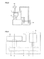
- a power unit 2, first pulley 3, and second pulley 4 are set in a rotary table 1.
- the power unit 2 and the first pulley 3 are disposed on the same axis (C-axis 7) and can rotate synchronously.
- a belt 5 is stretched between the first and second pulleys 3 and 4 such that the rotation of the power unit 2 can be transmitted to the second pulley 4 through the first pulley 3.
- a face plate 6 for securing a workpiece (not shown) is mounted outside the rotary table 1.
- the face plate 6 and the second pulley 4 are disposed on the same axis (D-axis 8) and can rotate synchronously.
- the power unit 2 and the face plate 6 can rotate synchronously.
- Japanese Patent No. 3862956 (corresponding to WO2000/024541 ) discloses a technique on a spindle device of a die-sinking electric discharge machine, capable of minimizing the parts count by disposing units ranging from a power unit to a mounting unit (equivalent to a face plate) on the same straight line.
- the rotary table disclosed in Japanese Patent Application Laid-Open No. 2003-25154 shown in FIG. 4 has the two axes, the C- and D-axes 7 and 8, which require the use of two bearings (not shown) and a space for securing the bearings. Thus, it is difficult to construct a compact, lightweight rotary table.
- the object of the present invention is to provide a compact, lightweight rotary table device, in which components of a rotary table are arranged differently from their conventional counterparts, and an electric discharge machine with the rotary table device.
- the rotary table comprises a face plate which is disposed in a machining tank and on which a workpiece is placed, and the electric discharge machine comprises a controller configured to control the rotary table to perform electric discharge machining.
- the rotary table further comprises a power unit configured to generate a driving force for rotating the face plate, a speed reducer connected to the power unit and configured to reduce the rotational speed of the power unit, a shaft to which the face plate is secured and which is connected to the speed reducer, a bearing that supports the shaft and/or the face plate, a rotation detector secured to the shaft and configured to detect a rotational position of the face plate, and a housing that accommodates therein the power unit, the speed reducer, the shaft, the bearing, and the rotation detector.
- the respective centers of rotation of the power unit and the speed reducer are disposed on one and the same axis, and the rotation detector is disposed in a space defined by an outer peripheral portion of the speed reducer and an inner wall of the housing.
- the rotary table comprises a face plate, which is disposed in a machining tank and on which a workpiece is placed, and the electric discharge machine comprises a controller configured to control the rotary table to perform electric discharge machining.
- the rotary table further comprises a power unit configured to generate a driving force for rotating the face plate, a speed reducer connected with the face plate, connected to the power unit, and configured to reduce the rotational speed of the power unit, a bearing supporting the face plate, a shaft secured to the bearing, a rotation detector secured to the shaft and configured to detect a rotational position of the face plate, and a housing that accommodates therein the power unit, the speed reducer, the shaft, the bearing, and the rotation detector.
- the respective centers of rotation of the power unit and the speed reducer are disposed on one and the same axis, and the rotation detector is disposed in a space defined by an outer peripheral portion of the speed reducer and an inner wall of the housing.
- a first aspect of a rotary table device for rotating a workpiece comprises a face plate on which the workpiece is placed, a power unit configured to generate a driving force for rotating the face plate, a speed reducer connected to the power unit and configured to reduce the rotational speed of the power unit, a shaft to which the face plate is secured and which is connected to the speed reducer, a bearing that supports the shaft and/or the face plate, a rotation detector secured to the shaft and configured to detect a rotational position of the face plate, and a housing that accommodates therein the power unit, the speed reducer, the shaft, the bearing, and the rotation detector.
- the respective centers of rotation of the power unit and the speed reducer are disposed on one and the same axis, and the rotation detector is disposed in a space defined by an outer peripheral portion of the speed reducer and an inner wall of the housing.
- a second aspect of the rotary table device for rotating a workpiece comprises a face plate on which the workpiece is placed, a power unit configured to generate a driving force for rotating the face plate, a speed reducer connected with the face plate, connected to the power unit, and configured to reduce the rotational speed of the power unit, a bearing supporting the face plate, a shaft secured to the bearing, a rotation detector secured to the shaft and configured to detect a rotational position of the face plate, and a housing that accommodates therein the power unit, the speed reducer, the shaft, the bearing, and the rotation detector.
- the respective centers of rotation of the power unit and the speed reducer are disposed on one and the same axis, and the rotation detector is disposed in a space defined by an outer peripheral portion of the speed reducer and an inner wall of the housing.
- a compact, lightweight rotary table device in which components of a rotary table are arranged differently from their conventional counterparts, and an electric discharge machine with the rotary table device.
- FIG. 1 A first example of a rotary table of an electric discharge machine according to the present invention will first be described with reference to FIG. 1 .
- a housing 18 of a rotary table 1 accommodates a power unit 2, speed reducer 10, fixing member 15, shaft 11, bearing 13, face plate 6, and rotation detector 14.
- the face plate 6 serves to fix a workpiece or a jig to which the workpiece is secured.
- a sealing mechanism 16 formed of a seal member 17 is disposed in a gap between the housing 18 and the face plate 6.
- the power unit 2 comprises, for example, an electric motor.
- the fixing member 15 is secured to the housing 18, and the power unit 2 and the speed reducer 10 are attached to the fixing member 15.
- the speed reducer 10 is connected to the power unit 2 and the speed-reduction side of the speed reducer 10 is connected to the shaft 11. Further, the face plate 6 is secured to the shaft 11. Thus, the rotary driving force of the power unit 2 is transmitted to the face plate 6 through the speed reducer 10 and the shaft 11.
- the speed reducer 10 connected to the power unit 2 reduces the rotational speed of the power unit 2.
- the power unit 2 and the speed reducer 10 are disposed in the housing 18 so that their respective centers of rotation are aligned on the same axis (E-axis 9).
- a bearing support portion 12 is provided on one end side of the housing 18 of the rotary table 1.
- the bearing 13 has an annular structure and is supported for rotation about the central axis (E-axis 9) by the bearing support portion 12.
- the shaft 11 is secured to the bearing 13.
- the face plate 6 may be configured to be secured to the bearing 13.
- the shaft 11 comprises a central portion 11a including the center of rotation and an outer peripheral portion 11b around the central portion 11a.
- the shaft 11 is shaped so that its outer peripheral portion 11b projects from the central portion 11a toward the power unit 2, thereby covering the speed reducer 10.
- the rotation detector 14 is mounted on an end portion 11c of the outer peripheral portion 11b of the shaft 11.
- the rotation detector 14 is a conventional one in which a read head (not shown) is secured to the housing 18 and an object to be detected (rotation detector 14) is secured to the shaft 11 during use.
- the shaft 11, face plate 6, and rotation detector 14 can rotate synchronously with the speed reducer 10. As this is done, the angular position of the face plate 6 can be accurately detected by the rotation detector 14.
- the face plate 6 can be positioned with high precision by feedback-controlling the power unit 2 based on an angular position signal output from the read head that detects the rotational state of the rotation detector 14.
- the rotation detector 14 By shaping the shaft 11, on which the rotation detector 14 is mounted, so as to cover the speed reducer 10, as described above, the rotation detector 14 can be disposed in a space between the outer peripheral portion (side surface) of the speed reducer 10 and the inner wall of the housing 18.
- an increase in the dimension of the rotary table 1 along the E-axis 9 can be suppressed, so that a compact, lightweight rotary table can be obtained at low cost.
- a face plate 6 is secured directly to a bearing 13.
- a speed reducer 10 is secured directly to the central part of the face plate 6. Since the bearing 13 has an annular structure, the speed reducer 10 can be moved toward and disposed in the bearing 13.
- a shaft 19 is attached to a side surface of the bearing 13 and a rotation detector 14 is secured to a rear end portion 19a of the shaft 19.
- the speed reducer 10 is connected to a power unit 2 and the speed-reduction side of the speed reducer 10 is connected to the face plate 6.
- the dimension of the rotary table 1 along an E-axis 9 is smaller than in the first example shown in FIG. 1 , so that a more compact rotary table can be obtained.
- the electric discharge machine comprises a controller 20, machining tank 21, and clean water tank 22.
- the controller 20 controls the entire electric discharge machine including the rotary table 1 shown in FIG. 1 or 2 .
- the controller 20 can receive a rotational position signal from the rotation detector 14 on the rotary table 1 and feedback-control the power unit 2 of the rotary table 1, thereby positioning the face plate 6 with high precision.
- the rotary table 1 (rotary table device) is disposed in the machining tank 21 in such a manner that the E-axis 9 extends in a vertical direction, horizontal direction, or some other direction.
- the workpiece is fixed on the face plate 6 of the rotary table 1 and subjected to electric discharge machining with the machining tank 21 filled with the machining fluid.
Landscapes
- Engineering & Computer Science (AREA)
- Mechanical Engineering (AREA)
- Electrical Discharge Machining, Electrochemical Machining, And Combined Machining (AREA)
- Machine Tool Units (AREA)
- Chemical & Material Sciences (AREA)
- Chemical Kinetics & Catalysis (AREA)
- Electrochemistry (AREA)
- General Details Of Gearings (AREA)
Applications Claiming Priority (1)
| Application Number | Priority Date | Filing Date | Title |
|---|---|---|---|
| JP2014080157A JP5887376B2 (ja) | 2014-04-09 | 2014-04-09 | 回転軸を有する放電加工機 |
Publications (2)
| Publication Number | Publication Date |
|---|---|
| EP2929971A1 true EP2929971A1 (de) | 2015-10-14 |
| EP2929971B1 EP2929971B1 (de) | 2019-05-22 |
Family
ID=54264314
Family Applications (1)
| Application Number | Title | Priority Date | Filing Date |
|---|---|---|---|
| EP15160862.7A Active EP2929971B1 (de) | 2014-04-09 | 2015-03-25 | Funkenerosionsmaschine mit drehtisch |
Country Status (4)
| Country | Link |
|---|---|
| US (1) | US10052704B2 (de) |
| EP (1) | EP2929971B1 (de) |
| JP (1) | JP5887376B2 (de) |
| CN (1) | CN104972184B (de) |
Families Citing this family (5)
| Publication number | Priority date | Publication date | Assignee | Title |
|---|---|---|---|---|
| JP6370767B2 (ja) * | 2015-11-25 | 2018-08-08 | ファナック株式会社 | 放電加工機用の回転テーブル装置 |
| US10272510B2 (en) * | 2016-01-14 | 2019-04-30 | United Technologies Corporation | Electrical discharge machining apparatus |
| KR102610650B1 (ko) | 2019-03-28 | 2023-12-05 | 써던 밀즈, 인코포레이티드 | 방염 직물 |
| US11891731B2 (en) | 2021-08-10 | 2024-02-06 | Southern Mills, Inc. | Flame resistant fabrics |
| US12176798B2 (en) * | 2022-01-07 | 2024-12-24 | Hiwin Technologies Corp. | Rotary table with leakage detection function |
Citations (4)
| Publication number | Priority date | Publication date | Assignee | Title |
|---|---|---|---|---|
| US4899998A (en) * | 1987-11-10 | 1990-02-13 | Hiroshi Teramachi | Rotational positioning device |
| WO2000024541A1 (fr) | 1998-10-27 | 2000-05-04 | Sodick Co., Ltd. | Systeme de broche pour machine d'usinage par etincelage servant a effectuer l'alesage |
| JP2003025154A (ja) | 2001-07-16 | 2003-01-29 | Amada Co Ltd | ワイヤカット放電加工機 |
| CN102581408A (zh) * | 2012-03-21 | 2012-07-18 | 苏州电加工机床研究所有限公司 | 电加工机床全浸式数控回转工作台密封结构及密封方法 |
Family Cites Families (14)
| Publication number | Priority date | Publication date | Assignee | Title |
|---|---|---|---|---|
| JPS6315038Y2 (de) * | 1981-01-21 | 1988-04-26 | ||
| US4469993A (en) * | 1981-03-03 | 1984-09-04 | Swanson Systems, Inc. | Programmable multiple position machine |
| JPH0297524U (de) * | 1988-08-31 | 1990-08-03 | ||
| JP2569067Y2 (ja) * | 1989-07-03 | 1998-04-22 | 帝人製機株式会社 | クランプ装置 |
| US5656229A (en) * | 1990-02-20 | 1997-08-12 | Nikon Corporation | Method for removing a thin film layer |
| JP3126366B2 (ja) * | 1990-04-13 | 2001-01-22 | 日本精工株式会社 | 直接駆動型回転割出装置 |
| JPH09248785A (ja) * | 1996-03-08 | 1997-09-22 | Nippon Thompson Co Ltd | 位置決め装置 |
| JP3940863B2 (ja) * | 1997-12-25 | 2007-07-04 | Smc株式会社 | インデックス装置 |
| CN1232801C (zh) | 2003-11-28 | 2005-12-21 | 清华大学 | 高精度超低速双轴伺服测试用的测试转台 |
| JP2008213098A (ja) | 2007-03-06 | 2008-09-18 | Mitsubishi Heavy Ind Ltd | 割り出しテーブル |
| CN201644962U (zh) * | 2010-01-19 | 2010-11-24 | 群基精密工业(苏州)有限公司 | 立式轮胎模具放电加工机 |
| CN102009201A (zh) * | 2010-11-05 | 2011-04-13 | 林颖 | 多工位可调速数控钻床 |
| CN103143846B (zh) | 2013-03-20 | 2014-12-03 | 江苏扬力数控机床有限公司 | 一种激光切割机转塔式喷嘴自动更换装置 |
| JP5684346B2 (ja) | 2013-08-26 | 2015-03-11 | ファナック株式会社 | 回転軸を有する放電加工機 |
-
2014
- 2014-04-09 JP JP2014080157A patent/JP5887376B2/ja active Active
-
2015
- 2015-03-25 EP EP15160862.7A patent/EP2929971B1/de active Active
- 2015-04-08 US US14/681,950 patent/US10052704B2/en active Active
- 2015-04-08 CN CN201510163265.8A patent/CN104972184B/zh active Active
Patent Citations (5)
| Publication number | Priority date | Publication date | Assignee | Title |
|---|---|---|---|---|
| US4899998A (en) * | 1987-11-10 | 1990-02-13 | Hiroshi Teramachi | Rotational positioning device |
| WO2000024541A1 (fr) | 1998-10-27 | 2000-05-04 | Sodick Co., Ltd. | Systeme de broche pour machine d'usinage par etincelage servant a effectuer l'alesage |
| JP3862956B2 (ja) | 1998-10-27 | 2006-12-27 | 株式会社ソディック | 形彫放電加工装置の主軸装置 |
| JP2003025154A (ja) | 2001-07-16 | 2003-01-29 | Amada Co Ltd | ワイヤカット放電加工機 |
| CN102581408A (zh) * | 2012-03-21 | 2012-07-18 | 苏州电加工机床研究所有限公司 | 电加工机床全浸式数控回转工作台密封结构及密封方法 |
Also Published As
| Publication number | Publication date |
|---|---|
| JP2015199172A (ja) | 2015-11-12 |
| CN104972184B (zh) | 2018-10-12 |
| US10052704B2 (en) | 2018-08-21 |
| EP2929971B1 (de) | 2019-05-22 |
| US20150290734A1 (en) | 2015-10-15 |
| CN104972184A (zh) | 2015-10-14 |
| JP5887376B2 (ja) | 2016-03-16 |
Similar Documents
| Publication | Publication Date | Title |
|---|---|---|
| US10052704B2 (en) | Electric discharge machine with rotary table | |
| JP5201681B2 (ja) | 工作機械用の角度割出し装置 | |
| TWI666079B (zh) | 轉塔刀具台及具備該轉塔刀具台的工具機 | |
| JP7397999B2 (ja) | ベルト伝動式アングルアタッチメントヘッド | |
| JP2008213098A (ja) | 割り出しテーブル | |
| KR101714054B1 (ko) | 직접 구동식 로터리 테이블 장치 | |
| JP2008155337A (ja) | 割出装置 | |
| CN205110896U (zh) | 一种多功能动力头 | |
| JP5608493B2 (ja) | サーボモータを用いた電動加工装置 | |
| KR101342928B1 (ko) | 이축 자동선회 헤드장치 | |
| KR20090079792A (ko) | 공작기계용 회전 인덱스 장치 | |
| JP6132695B2 (ja) | 工作機械用テーブル装置 | |
| JP2009285777A (ja) | スピンドル装置 | |
| KR101485559B1 (ko) | 수직형 nc 선반 | |
| RU2013154338A (ru) | Устройство для обработки деталей на фрезерном станке с чпу | |
| CN102248210B (zh) | 起重机回转支承平面加工专用工具 | |
| KR20090099272A (ko) | Cnc선반용 공구대의 터렛처짐 방지장치 | |
| JP2008023683A (ja) | 工作機械 | |
| CN104907859A (zh) | 一种小角度旋转定位夹紧装置 | |
| JP6607637B2 (ja) | 工作機械 | |
| KR101633741B1 (ko) | 부하직결형 모터(DD motor)를 사용한 로터리 테이블 | |
| KR20220004418A (ko) | 각도조절이 용이한 공작 기계용 유니버설 헤드 유닛 | |
| CN219232789U (zh) | 一种喷涂转台 | |
| CN110553841A (zh) | 音环检测机 | |
| JP2018075645A (ja) | 工具径可変主軸装置 |
Legal Events
| Date | Code | Title | Description |
|---|---|---|---|
| PUAI | Public reference made under article 153(3) epc to a published international application that has entered the european phase |
Free format text: ORIGINAL CODE: 0009012 |
|
| AK | Designated contracting states |
Kind code of ref document: A1 Designated state(s): AL AT BE BG CH CY CZ DE DK EE ES FI FR GB GR HR HU IE IS IT LI LT LU LV MC MK MT NL NO PL PT RO RS SE SI SK SM TR |
|
| AX | Request for extension of the european patent |
Extension state: BA ME |
|
| 17P | Request for examination filed |
Effective date: 20160406 |
|
| RBV | Designated contracting states (corrected) |
Designated state(s): AL AT BE BG CH CY CZ DE DK EE ES FI FR GB GR HR HU IE IS IT LI LT LU LV MC MK MT NL NO PL PT RO RS SE SI SK SM TR |
|
| STAA | Information on the status of an ep patent application or granted ep patent |
Free format text: STATUS: EXAMINATION IS IN PROGRESS |
|
| 17Q | First examination report despatched |
Effective date: 20180613 |
|
| GRAP | Despatch of communication of intention to grant a patent |
Free format text: ORIGINAL CODE: EPIDOSNIGR1 |
|
| STAA | Information on the status of an ep patent application or granted ep patent |
Free format text: STATUS: GRANT OF PATENT IS INTENDED |
|
| INTG | Intention to grant announced |
Effective date: 20190117 |
|
| GRAS | Grant fee paid |
Free format text: ORIGINAL CODE: EPIDOSNIGR3 |
|
| GRAA | (expected) grant |
Free format text: ORIGINAL CODE: 0009210 |
|
| STAA | Information on the status of an ep patent application or granted ep patent |
Free format text: STATUS: THE PATENT HAS BEEN GRANTED |
|
| AK | Designated contracting states |
Kind code of ref document: B1 Designated state(s): AL AT BE BG CH CY CZ DE DK EE ES FI FR GB GR HR HU IE IS IT LI LT LU LV MC MK MT NL NO PL PT RO RS SE SI SK SM TR |
|
| REG | Reference to a national code |
Ref country code: GB Ref legal event code: FG4D |
|
| REG | Reference to a national code |
Ref country code: CH Ref legal event code: EP |
|
| REG | Reference to a national code |
Ref country code: IE Ref legal event code: FG4D |
|
| REG | Reference to a national code |
Ref country code: DE Ref legal event code: R096 Ref document number: 602015030608 Country of ref document: DE |
|
| REG | Reference to a national code |
Ref country code: AT Ref legal event code: REF Ref document number: 1135509 Country of ref document: AT Kind code of ref document: T Effective date: 20190615 |
|
| REG | Reference to a national code |
Ref country code: NL Ref legal event code: MP Effective date: 20190522 |
|
| REG | Reference to a national code |
Ref country code: LT Ref legal event code: MG4D |
|
| PG25 | Lapsed in a contracting state [announced via postgrant information from national office to epo] |
Ref country code: FI Free format text: LAPSE BECAUSE OF FAILURE TO SUBMIT A TRANSLATION OF THE DESCRIPTION OR TO PAY THE FEE WITHIN THE PRESCRIBED TIME-LIMIT Effective date: 20190522 Ref country code: NO Free format text: LAPSE BECAUSE OF FAILURE TO SUBMIT A TRANSLATION OF THE DESCRIPTION OR TO PAY THE FEE WITHIN THE PRESCRIBED TIME-LIMIT Effective date: 20190822 Ref country code: ES Free format text: LAPSE BECAUSE OF FAILURE TO SUBMIT A TRANSLATION OF THE DESCRIPTION OR TO PAY THE FEE WITHIN THE PRESCRIBED TIME-LIMIT Effective date: 20190522 Ref country code: AL Free format text: LAPSE BECAUSE OF FAILURE TO SUBMIT A TRANSLATION OF THE DESCRIPTION OR TO PAY THE FEE WITHIN THE PRESCRIBED TIME-LIMIT Effective date: 20190522 Ref country code: PT Free format text: LAPSE BECAUSE OF FAILURE TO SUBMIT A TRANSLATION OF THE DESCRIPTION OR TO PAY THE FEE WITHIN THE PRESCRIBED TIME-LIMIT Effective date: 20190922 Ref country code: SE Free format text: LAPSE BECAUSE OF FAILURE TO SUBMIT A TRANSLATION OF THE DESCRIPTION OR TO PAY THE FEE WITHIN THE PRESCRIBED TIME-LIMIT Effective date: 20190522 Ref country code: LT Free format text: LAPSE BECAUSE OF FAILURE TO SUBMIT A TRANSLATION OF THE DESCRIPTION OR TO PAY THE FEE WITHIN THE PRESCRIBED TIME-LIMIT Effective date: 20190522 Ref country code: NL Free format text: LAPSE BECAUSE OF FAILURE TO SUBMIT A TRANSLATION OF THE DESCRIPTION OR TO PAY THE FEE WITHIN THE PRESCRIBED TIME-LIMIT Effective date: 20190522 Ref country code: HR Free format text: LAPSE BECAUSE OF FAILURE TO SUBMIT A TRANSLATION OF THE DESCRIPTION OR TO PAY THE FEE WITHIN THE PRESCRIBED TIME-LIMIT Effective date: 20190522 |
|
| PG25 | Lapsed in a contracting state [announced via postgrant information from national office to epo] |
Ref country code: RS Free format text: LAPSE BECAUSE OF FAILURE TO SUBMIT A TRANSLATION OF THE DESCRIPTION OR TO PAY THE FEE WITHIN THE PRESCRIBED TIME-LIMIT Effective date: 20190522 Ref country code: BG Free format text: LAPSE BECAUSE OF FAILURE TO SUBMIT A TRANSLATION OF THE DESCRIPTION OR TO PAY THE FEE WITHIN THE PRESCRIBED TIME-LIMIT Effective date: 20190822 Ref country code: GR Free format text: LAPSE BECAUSE OF FAILURE TO SUBMIT A TRANSLATION OF THE DESCRIPTION OR TO PAY THE FEE WITHIN THE PRESCRIBED TIME-LIMIT Effective date: 20190823 Ref country code: LV Free format text: LAPSE BECAUSE OF FAILURE TO SUBMIT A TRANSLATION OF THE DESCRIPTION OR TO PAY THE FEE WITHIN THE PRESCRIBED TIME-LIMIT Effective date: 20190522 |
|
| REG | Reference to a national code |
Ref country code: AT Ref legal event code: MK05 Ref document number: 1135509 Country of ref document: AT Kind code of ref document: T Effective date: 20190522 |
|
| PG25 | Lapsed in a contracting state [announced via postgrant information from national office to epo] |
Ref country code: SK Free format text: LAPSE BECAUSE OF FAILURE TO SUBMIT A TRANSLATION OF THE DESCRIPTION OR TO PAY THE FEE WITHIN THE PRESCRIBED TIME-LIMIT Effective date: 20190522 Ref country code: RO Free format text: LAPSE BECAUSE OF FAILURE TO SUBMIT A TRANSLATION OF THE DESCRIPTION OR TO PAY THE FEE WITHIN THE PRESCRIBED TIME-LIMIT Effective date: 20190522 Ref country code: CZ Free format text: LAPSE BECAUSE OF FAILURE TO SUBMIT A TRANSLATION OF THE DESCRIPTION OR TO PAY THE FEE WITHIN THE PRESCRIBED TIME-LIMIT Effective date: 20190522 Ref country code: EE Free format text: LAPSE BECAUSE OF FAILURE TO SUBMIT A TRANSLATION OF THE DESCRIPTION OR TO PAY THE FEE WITHIN THE PRESCRIBED TIME-LIMIT Effective date: 20190522 Ref country code: AT Free format text: LAPSE BECAUSE OF FAILURE TO SUBMIT A TRANSLATION OF THE DESCRIPTION OR TO PAY THE FEE WITHIN THE PRESCRIBED TIME-LIMIT Effective date: 20190522 Ref country code: DK Free format text: LAPSE BECAUSE OF FAILURE TO SUBMIT A TRANSLATION OF THE DESCRIPTION OR TO PAY THE FEE WITHIN THE PRESCRIBED TIME-LIMIT Effective date: 20190522 |
|
| REG | Reference to a national code |
Ref country code: DE Ref legal event code: R097 Ref document number: 602015030608 Country of ref document: DE |
|
| PG25 | Lapsed in a contracting state [announced via postgrant information from national office to epo] |
Ref country code: IT Free format text: LAPSE BECAUSE OF FAILURE TO SUBMIT A TRANSLATION OF THE DESCRIPTION OR TO PAY THE FEE WITHIN THE PRESCRIBED TIME-LIMIT Effective date: 20190522 Ref country code: SM Free format text: LAPSE BECAUSE OF FAILURE TO SUBMIT A TRANSLATION OF THE DESCRIPTION OR TO PAY THE FEE WITHIN THE PRESCRIBED TIME-LIMIT Effective date: 20190522 |
|
| PLBE | No opposition filed within time limit |
Free format text: ORIGINAL CODE: 0009261 |
|
| STAA | Information on the status of an ep patent application or granted ep patent |
Free format text: STATUS: NO OPPOSITION FILED WITHIN TIME LIMIT |
|
| PG25 | Lapsed in a contracting state [announced via postgrant information from national office to epo] |
Ref country code: TR Free format text: LAPSE BECAUSE OF FAILURE TO SUBMIT A TRANSLATION OF THE DESCRIPTION OR TO PAY THE FEE WITHIN THE PRESCRIBED TIME-LIMIT Effective date: 20190522 |
|
| 26N | No opposition filed |
Effective date: 20200225 |
|
| PG25 | Lapsed in a contracting state [announced via postgrant information from national office to epo] |
Ref country code: PL Free format text: LAPSE BECAUSE OF FAILURE TO SUBMIT A TRANSLATION OF THE DESCRIPTION OR TO PAY THE FEE WITHIN THE PRESCRIBED TIME-LIMIT Effective date: 20190522 |
|
| PG25 | Lapsed in a contracting state [announced via postgrant information from national office to epo] |
Ref country code: SI Free format text: LAPSE BECAUSE OF FAILURE TO SUBMIT A TRANSLATION OF THE DESCRIPTION OR TO PAY THE FEE WITHIN THE PRESCRIBED TIME-LIMIT Effective date: 20190522 |
|
| PG25 | Lapsed in a contracting state [announced via postgrant information from national office to epo] |
Ref country code: MC Free format text: LAPSE BECAUSE OF FAILURE TO SUBMIT A TRANSLATION OF THE DESCRIPTION OR TO PAY THE FEE WITHIN THE PRESCRIBED TIME-LIMIT Effective date: 20190522 |
|
| REG | Reference to a national code |
Ref country code: BE Ref legal event code: MM Effective date: 20200331 |
|
| PG25 | Lapsed in a contracting state [announced via postgrant information from national office to epo] |
Ref country code: LU Free format text: LAPSE BECAUSE OF NON-PAYMENT OF DUE FEES Effective date: 20200325 |
|
| REG | Reference to a national code |
Ref country code: DE Ref legal event code: R082 Ref document number: 602015030608 Country of ref document: DE Representative=s name: HL KEMPNER PATENTANWAELTE, SOLICITORS (ENGLAND, DE Ref country code: DE Ref legal event code: R082 Ref document number: 602015030608 Country of ref document: DE Representative=s name: HL KEMPNER PATENTANWALT, RECHTSANWALT, SOLICIT, DE Ref country code: DE Ref legal event code: R082 Ref document number: 602015030608 Country of ref document: DE Representative=s name: HL KEMPNER PARTG MBB, DE |
|
| PG25 | Lapsed in a contracting state [announced via postgrant information from national office to epo] |
Ref country code: IE Free format text: LAPSE BECAUSE OF NON-PAYMENT OF DUE FEES Effective date: 20200325 Ref country code: FR Free format text: LAPSE BECAUSE OF NON-PAYMENT OF DUE FEES Effective date: 20200331 |
|
| PG25 | Lapsed in a contracting state [announced via postgrant information from national office to epo] |
Ref country code: BE Free format text: LAPSE BECAUSE OF NON-PAYMENT OF DUE FEES Effective date: 20200331 |
|
| GBPC | Gb: european patent ceased through non-payment of renewal fee |
Effective date: 20200325 |
|
| PG25 | Lapsed in a contracting state [announced via postgrant information from national office to epo] |
Ref country code: GB Free format text: LAPSE BECAUSE OF NON-PAYMENT OF DUE FEES Effective date: 20200325 |
|
| PG25 | Lapsed in a contracting state [announced via postgrant information from national office to epo] |
Ref country code: MT Free format text: LAPSE BECAUSE OF FAILURE TO SUBMIT A TRANSLATION OF THE DESCRIPTION OR TO PAY THE FEE WITHIN THE PRESCRIBED TIME-LIMIT Effective date: 20190522 Ref country code: CY Free format text: LAPSE BECAUSE OF FAILURE TO SUBMIT A TRANSLATION OF THE DESCRIPTION OR TO PAY THE FEE WITHIN THE PRESCRIBED TIME-LIMIT Effective date: 20190522 |
|
| PG25 | Lapsed in a contracting state [announced via postgrant information from national office to epo] |
Ref country code: MK Free format text: LAPSE BECAUSE OF FAILURE TO SUBMIT A TRANSLATION OF THE DESCRIPTION OR TO PAY THE FEE WITHIN THE PRESCRIBED TIME-LIMIT Effective date: 20190522 Ref country code: IS Free format text: LAPSE BECAUSE OF FAILURE TO SUBMIT A TRANSLATION OF THE DESCRIPTION OR TO PAY THE FEE WITHIN THE PRESCRIBED TIME-LIMIT Effective date: 20190922 |
|
| PGFP | Annual fee paid to national office [announced via postgrant information from national office to epo] |
Ref country code: CH Payment date: 20250401 Year of fee payment: 11 |
|
| REG | Reference to a national code |
Ref country code: CH Ref legal event code: U11 Free format text: ST27 STATUS EVENT CODE: U-0-0-U10-U11 (AS PROVIDED BY THE NATIONAL OFFICE) Effective date: 20260401 |
|
| PGFP | Annual fee paid to national office [announced via postgrant information from national office to epo] |
Ref country code: DE Payment date: 20260219 Year of fee payment: 12 |