EP2927995B1 - Positive elektrodenleitung und alkalische sekundärbatterie - Google Patents
Positive elektrodenleitung und alkalische sekundärbatterie Download PDFInfo
- Publication number
- EP2927995B1 EP2927995B1 EP13858165.7A EP13858165A EP2927995B1 EP 2927995 B1 EP2927995 B1 EP 2927995B1 EP 13858165 A EP13858165 A EP 13858165A EP 2927995 B1 EP2927995 B1 EP 2927995B1
- Authority
- EP
- European Patent Office
- Prior art keywords
- lead
- half body
- positive electrode
- bent
- lead half
- Prior art date
- Legal status (The legal status is an assumption and is not a legal conclusion. Google has not performed a legal analysis and makes no representation as to the accuracy of the status listed.)
- Not-in-force
Links
Images




Classifications
-
- H—ELECTRICITY
- H01—ELECTRIC ELEMENTS
- H01M—PROCESSES OR MEANS, e.g. BATTERIES, FOR THE DIRECT CONVERSION OF CHEMICAL ENERGY INTO ELECTRICAL ENERGY
- H01M50/00—Constructional details or processes of manufacture of the non-active parts of electrochemical cells other than fuel cells, e.g. hybrid cells
- H01M50/50—Current conducting connections for cells or batteries
- H01M50/528—Fixed electrical connections, i.e. not intended for disconnection
-
- H—ELECTRICITY
- H01—ELECTRIC ELEMENTS
- H01M—PROCESSES OR MEANS, e.g. BATTERIES, FOR THE DIRECT CONVERSION OF CHEMICAL ENERGY INTO ELECTRICAL ENERGY
- H01M10/00—Secondary cells; Manufacture thereof
- H01M10/24—Alkaline accumulators
- H01M10/28—Construction or manufacture
-
- H—ELECTRICITY
- H01—ELECTRIC ELEMENTS
- H01M—PROCESSES OR MEANS, e.g. BATTERIES, FOR THE DIRECT CONVERSION OF CHEMICAL ENERGY INTO ELECTRICAL ENERGY
- H01M50/00—Constructional details or processes of manufacture of the non-active parts of electrochemical cells other than fuel cells, e.g. hybrid cells
- H01M50/50—Current conducting connections for cells or batteries
- H01M50/572—Means for preventing undesired use or discharge
- H01M50/574—Devices or arrangements for the interruption of current
- H01M50/581—Devices or arrangements for the interruption of current in response to temperature
-
- H—ELECTRICITY
- H01—ELECTRIC ELEMENTS
- H01M—PROCESSES OR MEANS, e.g. BATTERIES, FOR THE DIRECT CONVERSION OF CHEMICAL ENERGY INTO ELECTRICAL ENERGY
- H01M10/00—Secondary cells; Manufacture thereof
- H01M10/24—Alkaline accumulators
- H01M10/30—Nickel accumulators
-
- H—ELECTRICITY
- H01—ELECTRIC ELEMENTS
- H01M—PROCESSES OR MEANS, e.g. BATTERIES, FOR THE DIRECT CONVERSION OF CHEMICAL ENERGY INTO ELECTRICAL ENERGY
- H01M10/00—Secondary cells; Manufacture thereof
- H01M10/34—Gastight accumulators
- H01M10/345—Gastight metal hydride accumulators
-
- H—ELECTRICITY
- H01—ELECTRIC ELEMENTS
- H01M—PROCESSES OR MEANS, e.g. BATTERIES, FOR THE DIRECT CONVERSION OF CHEMICAL ENERGY INTO ELECTRICAL ENERGY
- H01M2200/00—Safety devices for primary or secondary batteries
- H01M2200/10—Temperature sensitive devices
- H01M2200/106—PTC
-
- Y—GENERAL TAGGING OF NEW TECHNOLOGICAL DEVELOPMENTS; GENERAL TAGGING OF CROSS-SECTIONAL TECHNOLOGIES SPANNING OVER SEVERAL SECTIONS OF THE IPC; TECHNICAL SUBJECTS COVERED BY FORMER USPC CROSS-REFERENCE ART COLLECTIONS [XRACs] AND DIGESTS
- Y02—TECHNOLOGIES OR APPLICATIONS FOR MITIGATION OR ADAPTATION AGAINST CLIMATE CHANGE
- Y02E—REDUCTION OF GREENHOUSE GAS [GHG] EMISSIONS, RELATED TO ENERGY GENERATION, TRANSMISSION OR DISTRIBUTION
- Y02E60/00—Enabling technologies; Technologies with a potential or indirect contribution to GHG emissions mitigation
- Y02E60/10—Energy storage using batteries
-
- Y—GENERAL TAGGING OF NEW TECHNOLOGICAL DEVELOPMENTS; GENERAL TAGGING OF CROSS-SECTIONAL TECHNOLOGIES SPANNING OVER SEVERAL SECTIONS OF THE IPC; TECHNICAL SUBJECTS COVERED BY FORMER USPC CROSS-REFERENCE ART COLLECTIONS [XRACs] AND DIGESTS
- Y02—TECHNOLOGIES OR APPLICATIONS FOR MITIGATION OR ADAPTATION AGAINST CLIMATE CHANGE
- Y02P—CLIMATE CHANGE MITIGATION TECHNOLOGIES IN THE PRODUCTION OR PROCESSING OF GOODS
- Y02P70/00—Climate change mitigation technologies in the production process for final industrial or consumer products
- Y02P70/50—Manufacturing or production processes characterised by the final manufactured product
Definitions
- the present invention relates to a positive electrode lead of an alkaline secondary battery.
- a commonly-known alkaline secondary battery such as a nickel-hydrogen secondary battery, if short-circuited due to, for example, external short-circuiting, may become heated to a high temperature for reasons of the low internal resistance and the amount of high internal energy of the battery.
- a commonly-known alkaline secondary battery includes a PTC (positive temperature coefficient) thermistor built in a positive electrode lead for electrically connecting the positive electrodes and the positive electrode terminal of an electrode group inside the battery for the purpose of ensuring safety in case of external short-circuiting (see, for example, Patent Document 1).
- This PTC thermistor is an electronic component composed of electrically-conductive particles.
- the PTC thermistor is low in electrical resistance value under normal conditions, and therefore, exhibits superior electrical conductivity.
- the PTC thermistor has characteristics in which the electrical resistance value of the thermistor increases drastically when the temperature thereof rises to a predetermined value.
- an excess current flows in the PTC thermistor built in the positive electrode lead if external short-circuiting occurs in the alkaline secondary battery for some reason, and therefore, the temperature of the battery rises.
- the electrical resistance value of the PTC thermistor increases, thereby suppressing a current flowing from the electrode group to the positive electrode terminal at the PTC thermistor-mounted portion of the positive electrode lead.
- the excess current flowing within the alkaline secondary battery is thus suppressed, thereby preventing the alkaline secondary battery from becoming heated if external short-circuiting occurs.
- the positive electrode lead including the PTC thermistor built therein is configured by, for example, disposing two metallic strip-shaped bodies in series, partially overlapping the leading ends of the strip-shaped bodies with each other, and solder-joining the PTC thermistor between the separate and opposed leading ends of the strip-shaped bodies.
- the portion where the PTC thermistor is solder-joined is covered and protected with, for example, a protective member composed of alkali-resistant epoxy resin or the like. This is for the purpose of preventing the deterioration or the like of the PTC thermistor due to high-pressure oxygen generated inside the alkaline secondary battery and the deterioration or the like of soldered portions due to an alkaline ambient atmosphere inside the alkaline secondary battery.
- Patent Document 1 Japanese Patent Laid-Open No. 06-243856
- US 2006/044728 A1 describes a secondary protective element for a secondary battery.
- the secondary protective element includes: a functional element; a lead plate arranged on least one of upper and lower surfaces of the functional element; and at least one bending section arranged on a predetermined portion of the lead plate.
- WO 2011/138959 A1 describes a battery pack comprising a PTC device and a lead of which at least a part is placed on each of the metal electrodes in the PTC element and which is connected to the metal electrodes through an electrically conductive material, wherein an exposed part of the electrically conductive material is covered with a protective member.
- the metallic strip-shaped bodies need to be disposed in a limited narrow space between the positive electrode terminal and the electrode group inside the alkaline secondary battery, while bending parts of the metallic strip-shaped bodies, in a process for manufacturing the alkaline secondary battery. If at that time, the metallic strip-shaped bodies are bent at a portion where the protective member covering the solder-joined portion of the PTC thermistor is disposed, the protective member becomes broken. The solder-joined portion of the PTC thermistor therefore becomes exposed. This exposure may impair functions for protecting the PTC thermistor with the protective member. Even if the metallic strip-shaped bodies are bent on the outer side the portion where the protective member is disposed, the protective member may also become broken in some cases due to bending stress thus applied.
- An object of the present invention which has been accomplished in view of such circumstances as described above, is to provide a positive electrode lead of an alkaline secondary battery in which functions for protecting a PTC thermistor with a protective member are less likely to be impaired.
- a first aspect of the present invention is a positive electrode lead of an alkaline secondary battery comprising an exterior can the upper end of which is open; an electrode group formed by stacking positive electrodes and negative electrodes with separators interposed thereamong and housed in the exterior can along with an alkaline electrolytic solution; and a sealing body fixed to the open end of the exterior can while being insulated and including a cap plate for sealing the opening and a positive electrode terminal electrically connected to the cap plate, the positive electrode lead being disposed between the electrode group and the sealing body to electrically connect the positive electrodes of the electrode group and the sealing body and comprising a strip-shaped first lead half body electrically connected to the sealing body; a strip-shaped second lead half body electrically connected to the positive electrode; a PTC thermistor joined between the first lead half body and the second lead half body; and a protective member covering a portion of the positive electrode lead where the PTC thermistor is joined, wherein the second lead half body is provided with a portion to be bent when the second lead half body is
- Recessed grooves are formed in the portion of the second lead half body where the protective member is disposed.
- Each recessed groove has a shape elongated in a direction intersecting with a bend line of the portion to be bent, and therefore, the portion is improved in rigidity more than other portions. Accordingly, it is possible to reduce the possibility of the protective member becoming broken due to bending stress acting on the second lead half body in a process for manufacturing the alkaline secondary battery.
- the second lead half body where the protective member is disposed being improved in rigidity against bending more than other portions, it is possible to reduce the possibility of the second lead half body becoming bent at the portion where the protective member is disposed. Accordingly, the second lead half body securely bends at the portion where the second lead half body should bend in a process for manufacturing the alkaline secondary battery. It is therefore possible to reduce the possibility of the protective member becoming broken in a process for manufacturing the alkaline secondary battery.
- a second aspect of the present invention is a positive electrode lead, wherein in the above-described first aspect of the present invention, a plurality of the recessed grooves are provided in a line in the portion of the second lead half body covered with the protective member in a direction along the bend line.
- the portion of the second lead half body where the protective member is disposed can be improved in rigidity against bending even more than other portions. It is therefore possible to further reduce the possibility of the protective member becoming broken in a process for manufacturing an alkaline secondary battery. Consequently, according to the second aspect of present invention, it is possible to further reduce the possibility of functions for protecting the PTC thermistor with the protective member being impaired.
- a third aspect of the present invention is a positive electrode lead, wherein in the above-described first or second aspect of the present invention, a fold is previously formed in the portion of the second lead half body to be bent.
- the portion of the second lead half body to be bent bends more easily than other portions.
- the second lead half body bends more securely at the portion to be bent. Accordingly, it is possible to further reduce the possibility of the protective member becoming broken in a process for manufacturing an alkaline secondary battery. Consequently, according to the third aspect of the present invention, it is possible to further reduce the possibility of functions for protecting the PTC thermistor with the protective member being impaired.
- a fourth aspect of the present invention is a positive electrode lead, wherein in the above-described third aspect of the present invention, the second lead half body includes a step, in the portion thereof to be bent, formed of two folds formed by bending the second lead half body in the opposite bending direction.
- the positive electrode lead of the lead half body has a shape different from a shape that the lead half body has had conventionally. Accordingly, there may arise the need for process changes, equipment modifications and the like in a process for manufacturing an alkaline secondary battery.
- the second lead half body is bent at the portion thereof where the second lead half body should bend to form a fold in the portion and then the second lead half body is straightened back, it is possible to form the positive electrode lead into the same shape that the positive electrode lead has had conventionally. Since the portion where the fold is formed is once again bent, however, in a process for manufacturing an alkaline secondary battery, cracks or breakages may be produced at that time in the portion where the second lead half body is bent.
- a step formed of two folds formed by bending the second lead half body in the opposing bending direction is provided in the portion of the second lead half body to be bent.
- the second lead half body is maintained in the original straight state thereof, i.e., in substantially the same shape that the second lead half body has had conventionally. Accordingly, there arises no need for process changes, equipment modifications and the like in a process for manufacturing an alkaline secondary battery.
- the portion in which folds are formed by bending need not be brought back to the original straight state thereof when the second lead half body is straightened back to the original state thereof. Consequently, when the second lead half body is bent at the portion in which the folds are formed in a process for manufacturing an alkaline secondary battery, it is possible to reduce the possibility of cracks or breakages being produced in the bent portion.
- a fifth aspect of the present invention is a positive electrode lead, wherein in the above-described fourth aspect of the present invention, notches are additionally formed in the portion of the second lead half body to be bent.
- the notches enable the portion of the second lead half body to be bent to become more easily bendable.
- a sixth aspect of the present invention is a positive electrode lead, wherein in the above-described fifth aspect of the present invention, the notches of the second lead half body are formed on both side edges of the portion to be bent.
- the portion of the second lead half body to be bent on both side edges of which the notches are formed is easiest to bend. That is, the second lead half body is most easily bendable with a straight line connecting the notches on both side edges serving as a bend line. Consequently, the portion of the second lead half body to be bent can be more precisely bent along a desired bend line in a process for manufacturing an alkaline secondary battery.
- a seventh aspect of the present invention is a positive electrode lead, wherein in any one of the above-described first to sixth aspects of the present invention, notches are formed on both edges of the portion to be bent when the first lead half body is disposed between the electrode group and the sealing body.
- the portion of the first lead half body to be bent on both side edges of which the notches are formed is easiest to bend. That is, the first lead half body is most easily bendable with a straight line connecting the notches on the both side edges serving as a bend line. Consequently, the portion of the first lead half body to be bent can be more precisely bent along a desired bend line in a process for manufacturing an alkaline secondary battery. It is therefore possible to reduce the possibility of the protective member becoming broken.
- An eighth aspect of the present invention is a positive electrode lead, wherein in the above-described seventh aspect of the present invention, the first lead half body is provided with portions to be bent in a plurality of places, and notches are formed on both edges of each of the plurality of portions to be bent.
- the bending position and shape of the first lead half body can be flexibly adjusted accordingly in a process for manufacturing an alkaline secondary battery. Consequently, it is possible to further reduce the possibility of the protective member becoming broken in the process for manufacturing an alkaline secondary battery.
- a ninth aspect of the present invention is a positive electrode lead, wherein in the above-described seventh aspect of the present invention, the first lead half body is provided with portions to be bent in a plurality of places, and notches are formed on both edges of a region encompassing the plurality of portions to be bent.
- the bending position and shape of the first lead half body can be flexibly adjusted accordingly in a process for manufacturing an alkaline secondary battery. Consequently, it is possible to further reduce the possibility of the protective member becoming broken in the process for manufacturing an alkaline secondary battery.
- a tenth aspect of the present invention is a positive electrode lead, wherein in any one of the above-described first to ninth aspects of the present invention, the portion of the first lead half body or the second lead half body covered with the protective member is formed so as to be larger in plate thickness than portions outside the portion.
- the first lead half body or the second lead half body is more easily bendable on the outer side of the portion covered with the protective member. Consequently, it is possible to further reduce the possibility of the protective member becoming broken in a process for manufacturing an alkaline secondary battery.
- An eleventh aspect of the present invention is an alkaline secondary battery comprising an exterior can the upper end of which is open; an electrode group formed by stacking positive electrodes and negative electrodes with separators interposed thereamong and housed in the exterior can along with an alkaline electrolytic solution; a sealing body fixed to the open end of the exterior can while being insulated and including a cap plate for sealing the opening and a positive electrode terminal electrically connected to the cap plate; and a positive electrode lead according to any one of the above-described first to tenth aspects of the present invention
- the eleventh aspect of the present invention it is possible to obtain the working effect of any one of the above-described first to tenth aspects of the present invention in the alkaline secondary battery.
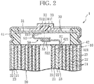
- the configuration of the nickel-hydrogen secondary battery 1 serving as an "alkaline secondary battery” will be described while referring to FIGS. 1 and 2 .
- FIG. 1 is a perspective view taken by partially cutting away the nickel-hydrogen secondary battery 1.
- FIG. 2 is a cross-sectional view illustrating an upper cross-section of the nickel-hydrogen secondary battery 1.
- the nickel-hydrogen secondary battery 1 is provided with an exterior can 10, an electrode group 20, a sealing body 30, and a positive electrode lead 50.
- the exterior can 10 is formed from a material having electrical conductivity and has a bottomed cylindrical shape the upper end of which is open, and a bottom wall 11 of the exterior can 10 functions as a negative electrode terminal.
- the electrode group 20 is housed in the exterior can 10 along with an alkaline electrolytic solution and includes positive electrodes 21, negative electrodes 22 and separators 23 all of which have a belt-like shape.
- the electrode group 20 is constructed by spirally winding the positive electrodes 21 and the negative electrodes 22 with the positive and negative electrodes alternately stacked with the separators interposed thereamong.
- the outermost periphery of the electrode group 20 is formed of part (outermost peripheral portion) of a negative electrode 22 and has contact with the inner peripheral wall of the exterior can 10. Accordingly, the exterior can 10 is electrically connected to the negative electrodes 22 of the electrode group 20.
- a circular insulating member 42 is disposed between the electrode group 20 and the cover plate 31, in order to prevent internal short-circuiting.
- a circular insulating member 43 is likewise disposed between the electrode group 20 and a bottom wall 11 of the exterior can 10, in order to prevent internal short-circuiting.
- the sealing body 30 is a structure fixed to an open end of the exterior can 10, while being insulated, to seal up the exterior can 10.
- the sealing body 30 includes the cover plate 31, a valve element 32 and a positive electrode terminal 33.
- the cover plate 31 is a circular plate-shaped member having electrical conductivity.
- a central through-hole 311 is formed in the center of the cover plate 31, and the valve element 32 for closing the central through-hole 311 is disposed on an outer surface of the cover plate 31.
- the valve element 32 is a member formed from an elastic material, such as rubber.
- the positive electrode terminal 33 is a flanged cylindrical-shaped member.
- the positive electrode terminal 33 is formed from a material having electrical conductivity and is provided with an unillustrated gas vent hole.
- the positive electrode terminal 33 is fixed to the upper surface of the cover plate 31, so as to cover the valve element 32, and is electrically connected to the cover plate 31, while pressing the valve element 32 against the cover plate 31.
- the cover plate 31 and a ring-shaped insulating gasket 41 surrounding this cover plate 31 are disposed inside the opening of the exterior can 10.
- the insulating gasket 41 is fixed to the open end 12 of the exterior can 10 by swaging the open end 12. That is, the cover plate 31 and the insulating gasket 41 airtightly plug up the opening of the exterior can 10 in conjunction with each other.
- the central through-hole 311 of the cover plate 31 is airtightly closed by the valve element 32. If a gas is generated inside the exterior can 10 and the internal pressure thereof rises, the valve element 32 is compressed by the internal pressure to open the central through-hole 311.
- the gas generated inside the exterior can 10 is released to the outside from the exterior can 10 through the central through-hole 311 and the gas vent hole of the positive electrode terminal 33. That is, the central through-hole 311 of the cover plate 31, the valve element 32 and the positive electrode terminal 33 constitute a safety valve that operates if a gas is generated inside the exterior can 10 and the internal pressure thereof rises.
- the positive electrode lead 50 is a structure disposed between the electrode group 20 and the sealing body 30 to electrically connect the positive electrodes 21 of the electrode group 20 and the positive electrode terminal 33 of the sealing body 30.
- the positive electrode lead 50 includes a first lead half body 51, a second lead half body 52, and a PTC thermistor 53.
- the first lead half body 51 and the second lead half body 52 are strip-shaped members composed of a material having electrical conductivity.
- the first lead half body 51 includes a cover plate connection end 511 electrically connected to the cover plate 31 of the sealing body 30, and a widened rectangular thermistor connection end 512 to which the PTC thermistor 53 is solder-joined.
- the second lead half body 52 includes a positive electrode connection end 521 electrically connected to the positive electrodes 21 of the electrode group 20 through a slit 421 provided in the insulating member 42, and a widened rectangular thermistor connection end 522 to which the PTC thermistor 53 is solder-joined.
- the PTC thermistor 53 is solder-joined between the thermistor connection end 512 of the first lead half body 51 and the thermistor connection end 522 of the second lead half body 52.
- the PTC thermistor 53 is composed of, for example, an insulating polymer in which electrically-conductive particles are dispersed. Since the electrically-conductive particles of such a PTC thermistor 53 have contact with one another under normal conditions, the PTC thermistor 53 has a low electrical resistance value and exhibits superior electrical conductivity. On the other hand, if external short-circuiting occurs in the nickel-hydrogen secondary battery 1, a large current flows in the PTC thermistor 53 and the thermistor becomes heated. Accordingly, the insulating polymer as a whole expands due to this heat. Consequently, electrically-conductive particles having contact with one another decrease in number, and therefore, the electrical resistance value increases drastically.
- the PTC thermistor 53 By taking advantage of such characteristics of the PTC thermistor 53, it is possible to prevent overcurrents generated when external short-circuiting occurs.
- the PTC thermistor 53 when freed from heat generation and cooled down, reverts to the original state of being low in electrical resistance value since the insulating polymer contracts.
- the operating temperature of the PTC thermistor 53 is preferably set to the range from 80°C to 100°C. The reason for this is that since a temperature difference arises between the interior and the external surface of the nickel-hydrogen secondary battery 1, the external surface temperature of the battery can be suppressed to 70°C or lower even if the operating temperature of the PTC thermistor 53 is set to the range from 80°C to 100°C.
- the surface temperature of the nickel-hydrogen secondary battery 1 is approximately 50°C to 55°C even if the PTC thermistor 53 of the nickel-hydrogen secondary battery 1 become heated and the temperature of the thermistor rises to 80°C to 100°C.
- a first embodiment of the positive electrode lead 50 according to the present invention will be described while referring to FIGS. 3 to 5 .
- FIGS. 3 to 5 illustrate the positive electrode lead 50 as a component before being built into the nickel-hydrogen secondary battery 1.
- FIG. 3 is a plan view of the positive electrode lead 50 of the first embodiment.
- FIG. 4 is a side view of the positive electrode lead 50 of the first embodiment.
- FIG. 5 is a cross-sectional view illustrating the I-I cross-section of FIG. 3 .
- the positive electrode lead 50 comprises a protective member 54 (not illustrated in FIGS. 1 and 2 ) for covering the portions of the first lead half body 51 and the second lead half body 52 where the PTC thermistor 53 is solder-joined.
- the protective member 54 is incorporated in order to prevent the deterioration or the like of the PTC thermistor 53 due to high-pressure oxygen generated inside the nickel-hydrogen secondary battery 1 and the deterioration or the like of soldered portions due to an alkaline ambient atmosphere inside the nickel-hydrogen secondary battery 1.
- the protective member 54 is composed of, for example, alkali-resistant epoxy resin.
- a portion to be bent (bend line A) when the positive electrode lead 50 is placed between the electrode group 20 and the sealing body 30 is disposed on the outer side of the portion covered with the protective member 54.
- a notch 513 is formed on each of both side edges of the portion to be bent.
- the second lead half body 52 includes a concave portion 523 formed in the thermistor connection end 522.
- the PTC thermistor 53 is placed in the concave portion 523.
- the concave portion 523 enables the area of the PTC thermistor 53 exposed between the thermistor connection end 512 of the first lead half body 51 and the thermistor connection end 522 of the second lead half body 52 to be decreased as much as possible.
- a portion to be bent (bend line B) when the positive electrode lead 50 is placed between the electrode group 20 and the sealing body 30 is disposed on the outer side of the portion covered with the protective member 54.
- three recessed grooves 524 are formed in the portion of the second lead half body 52 covered with the protective member 54.
- the three recessed grooves 524 have a shape elongated in a direction intersecting with the bend line B of the portion to be bent. These three recessed grooves 524 are formed by means of a drawing process and provided in a line in a direction along the bend line B.
- the portion of the second lead half body 52 where the protective member 54 is disposed is improved in rigidity against bending more than other portions, as the result of the recessed grooves 524 being formed in the portion. Accordingly, it is possible to reduce the possibility of the protective member 54 becoming broken due to bending stress acting on the second lead half body 52 in a process for manufacturing the nickel-hydrogen secondary battery 1. It is therefore possible to reduce the possibility of functions for protecting the PTC thermistor 53 with the protective member 54 being impaired.
- the portion of the second lead half body 52 where the protective member 54 is disposed is improved in rigidity against bending more than other portions, it is possible to reduce the possibility of the second lead half body 52 becoming bent at the portion where the protective member 54 is disposed. Accordingly, the second lead half body 52 securely bends at the portion (bend line B) where the second lead half body 52 should bend in a process for manufacturing the nickel-hydrogen secondary battery 1.
- the number of recessed grooves 524 is not limited in particular to 3. Needless to say, even only one recessed groove 524, for example, has effect. Increasing the number of recessed grooves 524 enables the portion of the second lead half body 52 where the protective member 54 is disposed to be further improved in rigidity against bending more than other portions and is, therefore, preferable.
- two folds 526 are previously formed in the portion (bend line B) of the second lead half body 52 to be bent. These folds are not essential constituent elements of the present invention, but make the portion of the second lead half body 52 to be bent more easily bendable than other portions. Accordingly, the second lead half body 52 more securely bends at the portion where the second lead half body 52 should bend.
- the protective member 54 becomes broken in a process for manufacturing the nickel-hydrogen secondary battery 1. It is therefore possible to further reduce the possibility of functions for protecting the PTC thermistor 53 with the protective member 54 being impaired.
- the two folds 526 are formed by bending the second lead half body 52 in the opposing bending direction, and a step 525 is formed of the folds 526.
- This step 525 is not an essential constituent element of the present invention.
- the second lead half body 52 is maintained in the original straight state thereof, i.e., in substantially the same shape that the second lead half body 52 has had conventionally. Accordingly, there arises no need for process changes, equipment modifications and the like in the process for manufacturing the nickel-hydrogen secondary battery 1.
- the portion in which folds 526 are formed by bending need not be brought back to the original straight state thereof when the second lead half body 52 is straightened back to the original state thereof. Consequently, when the second lead half body 52 is bent at the step 525 in the process for manufacturing the nickel-hydrogen secondary battery 1, it is possible to reduce the possibility of cracks or breakages being produced in the bent portion.
- a notch 527 is further formed on each of both side edges of the portion of the second lead half body 52 to be bent.
- These notches 527 are not essential constituent elements of the present invention, but make the portion of the second lead half body 52 on both side edges of which the notches 527 are formed most easily bendable. That is, the second lead half body 52 is most easily bendable with a straight line connecting the notches 527 on the both side edges serving as a bend line B. Consequently, the portion of the second lead half body 52 to be bent can be more precisely bent along a desired bend line B in the process for manufacturing the nickel-hydrogen secondary battery 1.
- the present invention it is possible to provide the positive electrode lead 50 of an alkaline secondary battery in which functions for protecting the PTC thermistor 53 with the protective member 54 are less likely impaired.
- recessed grooves 524, step 525, folds 526, and notches 527 of the second lead half body 52 may be provided in the first lead half body 51 instead, or in both the first lead half body 51 and the second lead half body 52.
- a second embodiment of the positive electrode lead 50 according to the present invention will be described while referring to FIGS. 6 and 7 .
- FIG. 6 illustrates the positive electrode lead 50 as a component before being built into the nickel-hydrogen secondary battery 1 and is a plan view of the positive electrode lead 50 of the second embodiment.
- FIG. 7 illustrates the positive electrode lead 50 of the second embodiment after having been built into the nickel-hydrogen secondary battery 1 and is a cross-sectional side view of a principal part of the nickel-hydrogen secondary battery 1.
- portions to be bent (bend lines A and C) when the positive electrode lead 50 is placed between the electrode group 20 and the sealing body 30 are disposed in a plurality of places on the outer side of the portion of the first lead half body 51 covered with the protective member 54.
- notches 513 and 514 are formed on both edges of each of the plurality of portions to be bent. More specifically, in the positive electrode lead 50 of the second embodiment, a notch 513 is formed on each of both side edges of the portion to be bent shown by the bend line A, and a notch 514 is likewise formed on each of both side edges of the portion to be bent shown by the bend line C.
- the bending position and shape of the first lead half body 51 can be flexibly adjusted accordingly in a process for manufacturing the nickel-hydrogen secondary battery 1. Consequently, it is possible to further reduce the possibility of the protective member 54 becoming broken in the process for manufacturing the nickel-hydrogen secondary battery 1.
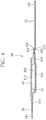
- a third embodiment of the positive electrode lead 50 according to the present invention will be described while referring to FIG 8 .
- FIG. 8 illustrates the positive electrode lead 50 as a component before being built into the nickel-hydrogen secondary battery 1 and is a plan view of the positive electrode lead 50 of the third embodiment.
- portions to be bent (bend lines A and C) when the positive electrode lead 50 is placed between the electrode group 20 and the sealing body 30 are disposed in a plurality of places on the outer side of the portion of the first lead half body 51 covered with the protective member 54.
- notches 515 are formed on both edges of a region encompassing the plurality of portions to be bent. More specifically, each notch 513 has a shape having a width of length L1 encompassing the plurality of portions to be bent and a depth of length L2 shorter than L1.
- the bending position and shape of the first lead half body 51 can be flexibly adjusted accordingly in a process for manufacturing the nickel-hydrogen secondary battery 1, as in the second embodiment. Consequently, it is possible to further reduce the possibility of the protective member 54 becoming broken in the process for manufacturing the nickel-hydrogen secondary battery 1.
- a fourth embodiment of the positive electrode lead 50 according to the present invention will be described while referring to FIG 9 .
- FIG. 9 illustrates the positive electrode lead 50 as a component before being built into the nickel-hydrogen secondary battery 1 and is a side view of the positive electrode lead 50 of the fourth embodiment.
- the portions of the first lead half body 51 and the second lead half body 52 covered with the protective member 54 are formed so as to be larger in plate thickness than portions outside those portions. According to the fourth embodiment of the positive electrode lead 50 configured as described above, the first lead half body 51 and the second lead half body 52 are more easily bendable on the outer side of the portions covered with the protective member 54. Consequently, it is possible to further reduce the possibility of the protective member 54 becoming broken in a process for manufacturing the nickel-hydrogen secondary battery 1.
- the portion of only the first lead half body 51 or the second lead half body 52 covered with the protective member 54 may be formed so as to be larger in plate thickness than other portions.
Landscapes
- Chemical & Material Sciences (AREA)
- Chemical Kinetics & Catalysis (AREA)
- Electrochemistry (AREA)
- General Chemical & Material Sciences (AREA)
- Engineering & Computer Science (AREA)
- Manufacturing & Machinery (AREA)
- Connection Of Batteries Or Terminals (AREA)
Claims (11)
- Positive Elektrodenleitung (50) für eine alkalische Sekundärbatterie, aufweisend eine Außenhülse (10), deren oberes Ende offen ist; eine Elektrodengruppe (20), die durch Aufeinanderschichten von positiven Elektroden (21) und negativen Elektroden (22) mit dazwischenliegenden Separatoren (23) gebildet wird und zusammen mit einer alkalischen Elektrolytlösung in der Außenhülse(10) aufgenommen ist; und einen Dichtungskörper (30), der an dem offenen Ende der Außenhülse (10) befestigt ist und gleichzeitig isoliert wird und eine Deckelplatte zum Verschließen der Öffnung und einen positiven Elektrodenanschluss umfasst, der mit der Deckelplatte elektrisch verbunden ist, wobei die positive Elektrodenleitung (50) zwischen der Elektrodengruppe (20) und dem Dichtungskörper (30) angeordnet werden kann, um die positiven Elektroden (21) der Elektrodengruppe (20) und den Dichtungskörper (30) elektrisch zu verbinden, die positive Elektrodenleitung (50) aufweisend:einen streifenförmigen, ersten Leitungs-Halbkörper (51), der mit dem Dichtungskörper (30) elektrisch verbindbar ist;einen streifenförmigen, zweiten Leitungs-Halbkörper (52), der mit der positiven Elektrode elektrisch verbindbar ist;einen Kaltleiter (53), der zwischen dem ersten Leitungs-Halbkörper (51) und dem zweiten Leitungs-Halbkörper (52) eingebracht ist;ein Schutzglied (54), das einen Abschnitt der positiven Elektrodenleitung (50) bedeckt, an den der Kaltleiter (53) anschließt;wobei der zweite Leitungs-Halbkörper (52) mit einem zu biegenden Abschnitt versehen ist, wenn der zweite Leitungs-Halbkörper (52) zwischen der Elektrodengruppe (20) und dem Dichtungskörper (30) an der Außenseite des mit dem Schutzglied (54) bedeckten Abschnitts angeordnet ist,
dadurch gekennzeichnet, dasseine vertiefte Nut (524) in dem Abschnitt des mit dem Schutzglied (54) bedeckten zweiten Leitungs-Halbkörpers gebildet ist, und die vertiefte Nut (524) eine Form hat, die in einer sich mit einer Biegelinie überschneidenden Richtung (B) des zu biegenden Abschnitts länglich ist. - Positive Elektrodenleitung nach Anspruch 1, wobei eine Vielzahl von vertieften Nuten (524) in dem Abschnitt des mit dem Schutzglied (54) bedeckten zweiten Leitungs-Halbkörpers (52) in einer Linie in einer Richtung entlang der Biegelinie (B) vorgesehen sind.
- Positive Elektrodenleitung nach Anspruch 1 oder 2, wobei in dem Abschnitt des zu biegenden, zweiten Leitungs-Halbkörpers (52) vorab ein Falz (526) gebildet wird.
- Positive Elektrodenleitung nach Anspruch 3, wobei der zweite Leitungs-Halbkörper (52) in seinem zu biegenden Abschnitt eine Stufe (525) umfasst, die aus zwei Falzen (526) gebildet ist, die gebildet werden, indem der zweite Leitungs-Halbkörper (52) in der entgegengesetzten Biegerichtung gebogen wird.
- Positive Elektrodenleitung nach Anspruch 4, wobei zusätzlich Kerben (527) in dem Abschnitt des zu biegenden zweiten Leitungs-Halbkörpers (52) gebildet sind.
- Positive Elektrodenleitung nach Anspruch 5, wobei die Kerben (527) des zweiten Leitungs-Halbkörpers (52) an beiden Seitenkanten des zu biegenden Abschnitts gebildet sind.
- Positive Elektrodenleitung nach einem der Ansprüche 1 bis 6, wobei Kerben (513) an beiden Kanten des zu biegenden Abschnitts gebildet sind, wenn der erste Leitungs-Halbkörper (51) zwischen der Elektrodengruppe (20) und dem Dichtungskörper (30) angeordnet ist.
- Positive Elektrodenleitung nach Anspruch 7, wobei der erste Leitungs-Halbkörper (51) an einer Vielzahl von Stellen mit zu biegenden Abschnitten versehen ist, und Kerben (513; 514) an beiden Kanten von jedem der Vielzahl von zu biegenden Abschnitten gebildet sind.
- Positive Elektrodenleitung nach Anspruch 7, wobei der erste Leitungs-Halbkörper (51) an einer Vielzahl von Stellen mit zu biegenden Abschnitten versehen ist, und Kerben (513; 514) an beiden Kanten eines die Vielzahl von zu biegenden Abschnitten umgebenden Bereichs gebildet sind.
- Positive Elektrodenleitung nach einem der Ansprüche 1 bis 9, wobei der Abschnitt des ersten Leitungs-Halbkörpers (51) oder des zweiten Leitungs-Halbkörpers (52), der mit dem Schutzglied (54) bedeckt ist, derart gebildet ist, dass er eine größere Plattendicke als Abschnitte außerhalb des Abschnitts hat.
- Alkalische Sekundärbatterie, aufweisend:eine Außenhülse (10), deren oberes Ende offen ist;eine Elektrodengruppe (20), die durch Aufeinanderschichten von positiven Elektroden (21) und negativen Elektroden (22) mit dazwischenliegenden Separatoren (23) gebildet wird und zusammen mit einer alkalischen Elektrolytlösung in der Außenhülse (10) aufgenommen wird;einen Dichtungskörper (30), der an dem offenen Ende der Außenhülse (10) befestigt ist und gleichzeitig isoliert wird und eine Deckelplatte zum Verschließen der Öffnung und einen positiven Elektrodenanschluss (33) umfasst, der mit der Deckelplatte elektrisch verbunden ist; undeine positive Elektrodenleitung (50) nach einem der Ansprüche 1 bis 10.
Applications Claiming Priority (2)
| Application Number | Priority Date | Filing Date | Title |
|---|---|---|---|
| JP2012261984 | 2012-11-30 | ||
| PCT/JP2013/081758 WO2014084203A1 (ja) | 2012-11-30 | 2013-11-26 | 正極リード、アルカリ二次電池 |
Publications (4)
| Publication Number | Publication Date |
|---|---|
| EP2927995A1 EP2927995A1 (de) | 2015-10-07 |
| EP2927995A4 EP2927995A4 (de) | 2016-08-10 |
| EP2927995B1 true EP2927995B1 (de) | 2018-05-30 |
| EP2927995B8 EP2927995B8 (de) | 2018-11-21 |
Family
ID=50827839
Family Applications (1)
| Application Number | Title | Priority Date | Filing Date |
|---|---|---|---|
| EP13858165.7A Not-in-force EP2927995B8 (de) | 2012-11-30 | 2013-11-26 | Positive elektrodenleitung und alkalische sekundärbatterie |
Country Status (5)
| Country | Link |
|---|---|
| US (1) | US9935307B2 (de) |
| EP (1) | EP2927995B8 (de) |
| JP (1) | JP6193261B2 (de) |
| CN (1) | CN104838521B (de) |
| WO (1) | WO2014084203A1 (de) |
Families Citing this family (6)
| Publication number | Priority date | Publication date | Assignee | Title |
|---|---|---|---|---|
| JP6395484B2 (ja) * | 2014-07-15 | 2018-09-26 | Fdk株式会社 | 正極リード、アルカリ二次電池 |
| RU2643733C2 (ru) * | 2016-05-04 | 2018-02-05 | Федеральное государственное бюджетное учреждение науки Институт физики металлов имени М.Н. Михеева Уральского отделения Российской академии наук (ИФМ УрО РАН) | СПОСОБ ИЗГОТОВЛЕНИЯ РЕЗИСТИВНОГО МАТЕРИАЛА ИЗ УПОРЯДОЧИВАЮЩЕГОСЯ СПЛАВА НА ОСНОВЕ Cu-Pd |
| JP7093199B2 (ja) * | 2018-02-16 | 2022-06-29 | Fdk株式会社 | 封口体及び電池 |
| JP7128666B2 (ja) * | 2018-06-11 | 2022-08-31 | Fdk株式会社 | 二次電池 |
| CN212625970U (zh) * | 2020-05-12 | 2021-02-26 | 路华置富电子(深圳)有限公司 | 极耳及使用该极耳的电池结构 |
| WO2025159107A1 (ja) * | 2024-01-25 | 2025-07-31 | パナソニックIpマネジメント株式会社 | 円筒形電池 |
Citations (1)
| Publication number | Priority date | Publication date | Assignee | Title |
|---|---|---|---|---|
| WO2011138959A1 (ja) * | 2010-05-06 | 2011-11-10 | タイコエレクトロニクスジャパン合同会社 | Ptcデバイスおよびそれを有する2次電池 |
Family Cites Families (11)
| Publication number | Priority date | Publication date | Assignee | Title |
|---|---|---|---|---|
| JPH06243856A (ja) | 1993-02-15 | 1994-09-02 | Japan Storage Battery Co Ltd | 蓄電素子 |
| US20030026053A1 (en) * | 2001-08-06 | 2003-02-06 | James Toth | Circuit protection device |
| JP4923379B2 (ja) | 2003-10-27 | 2012-04-25 | ソニー株式会社 | 二次電池および電池パック |
| KR100601533B1 (ko) * | 2004-07-28 | 2006-07-19 | 삼성에스디아이 주식회사 | 이차전지용 이차보호소자 |
| CN103996883B (zh) * | 2004-08-26 | 2017-01-11 | 株式会社杰士汤浅国际 | 密闭型镍氢电池 |
| JP4530169B2 (ja) * | 2005-12-09 | 2010-08-25 | Tdk株式会社 | サーミスタ装置、及び、サーミスタ装置の製造方法 |
| JP4997819B2 (ja) * | 2006-04-28 | 2012-08-08 | トヨタ自動車株式会社 | 電池モジュール |
| EP2506338B1 (de) * | 2007-11-29 | 2013-11-13 | LG Chem, Ltd. | PCM-verwendendes Batteriepack mit Sicherheitselement |
| US8399116B2 (en) * | 2007-12-25 | 2013-03-19 | Byd Co. Ltd. | Optimized dimensional relationships for an electrochemical cell having a coiled core |
| ES2532968T3 (es) * | 2010-09-01 | 2015-04-06 | Fdk Corporation | Pila |
| JP2012054099A (ja) * | 2010-09-01 | 2012-03-15 | Fdk Twicell Co Ltd | 電池 |
-
2013
- 2013-11-26 JP JP2014550194A patent/JP6193261B2/ja not_active Expired - Fee Related
- 2013-11-26 WO PCT/JP2013/081758 patent/WO2014084203A1/ja not_active Ceased
- 2013-11-26 US US14/647,820 patent/US9935307B2/en not_active Expired - Fee Related
- 2013-11-26 EP EP13858165.7A patent/EP2927995B8/de not_active Not-in-force
- 2013-11-26 CN CN201380062530.2A patent/CN104838521B/zh not_active Expired - Fee Related
Patent Citations (2)
| Publication number | Priority date | Publication date | Assignee | Title |
|---|---|---|---|---|
| WO2011138959A1 (ja) * | 2010-05-06 | 2011-11-10 | タイコエレクトロニクスジャパン合同会社 | Ptcデバイスおよびそれを有する2次電池 |
| US20130202917A1 (en) * | 2010-05-06 | 2013-08-08 | Fdk Twicell Co., Ltd. | PTC Device and Secondary Battery Equipped with Same |
Also Published As
| Publication number | Publication date |
|---|---|
| EP2927995B8 (de) | 2018-11-21 |
| US20150303445A1 (en) | 2015-10-22 |
| JPWO2014084203A1 (ja) | 2017-01-05 |
| CN104838521B (zh) | 2017-04-12 |
| EP2927995A4 (de) | 2016-08-10 |
| US9935307B2 (en) | 2018-04-03 |
| CN104838521A (zh) | 2015-08-12 |
| EP2927995A1 (de) | 2015-10-07 |
| WO2014084203A1 (ja) | 2014-06-05 |
| JP6193261B2 (ja) | 2017-09-06 |
Similar Documents
| Publication | Publication Date | Title |
|---|---|---|
| US9478774B2 (en) | Rechargeable battery | |
| US9935307B2 (en) | Positive electrode lead and alkaline secondary battery | |
| JP5517974B2 (ja) | 二次電池 | |
| US9685650B2 (en) | Electric storage device including current interruption device | |
| EP2479830B1 (de) | Sekundärbatterie mit einem flexiblen Stromsammler | |
| EP3046160B1 (de) | Wiederaufladbare batterie und packung dafür | |
| CN105789493B (zh) | 可再充电电池和可再充电电池组 | |
| CN102208594B (zh) | 二次电池 | |
| US8871378B2 (en) | Secondary battery including a cap assembly having a protection circuit assembly | |
| EP2325924B1 (de) | Sekundärbatterie mit Kurzschlussvorrichtung | |
| JP2009224325A (ja) | 円筒型二次電池 | |
| CN103247817A (zh) | 可再充电电池 | |
| BRPI0820355B1 (pt) | pacote de bateria secundária de estrutura compacta | |
| CN109417151B (zh) | 应用汇流条的电池单元 | |
| US20150024262A1 (en) | Rechargeable battery | |
| US20120070697A1 (en) | Prismatic secondary battery | |
| KR101093401B1 (ko) | 캡 업 플레이트 및 이를 구비하는 원통형 이차전지 | |
| EP2424007B1 (de) | Wiederaufladbare Batterie | |
| US9728764B2 (en) | Alkaline storage battery | |
| KR101613499B1 (ko) | 벤딩된 연결부를 구비한 이차 전지 팩 | |
| KR20160100673A (ko) | 배터리 팩 | |
| JP6395484B2 (ja) | 正極リード、アルカリ二次電池 |
Legal Events
| Date | Code | Title | Description |
|---|---|---|---|
| PUAI | Public reference made under article 153(3) epc to a published international application that has entered the european phase |
Free format text: ORIGINAL CODE: 0009012 |
|
| 17P | Request for examination filed |
Effective date: 20150527 |
|
| AK | Designated contracting states |
Kind code of ref document: A1 Designated state(s): AL AT BE BG CH CY CZ DE DK EE ES FI FR GB GR HR HU IE IS IT LI LT LU LV MC MK MT NL NO PL PT RO RS SE SI SK SM TR |
|
| AX | Request for extension of the european patent |
Extension state: BA ME |
|
| DAX | Request for extension of the european patent (deleted) | ||
| RA4 | Supplementary search report drawn up and despatched (corrected) |
Effective date: 20160711 |
|
| RIC1 | Information provided on ipc code assigned before grant |
Ipc: H01M 10/30 20060101ALN20160705BHEP Ipc: H01M 10/34 20060101ALN20160705BHEP Ipc: H01M 2/22 20060101ALI20160705BHEP Ipc: H01M 2/34 20060101AFI20160705BHEP |
|
| RAP1 | Party data changed (applicant data changed or rights of an application transferred) |
Owner name: FDK CORPORATION Owner name: LITTELFUSE JAPAN G.K. |
|
| GRAP | Despatch of communication of intention to grant a patent |
Free format text: ORIGINAL CODE: EPIDOSNIGR1 |
|
| RIC1 | Information provided on ipc code assigned before grant |
Ipc: H01M 2/34 20060101AFI20171027BHEP Ipc: H01M 10/34 20060101ALN20171027BHEP Ipc: H01M 10/30 20060101ALN20171027BHEP Ipc: H01M 2/22 20060101ALI20171027BHEP |
|
| INTG | Intention to grant announced |
Effective date: 20171204 |
|
| RIN1 | Information on inventor provided before grant (corrected) |
Inventor name: WADA, SATOSHI Inventor name: MIZUKAMI, YOHEI Inventor name: IDO, ERIKA Inventor name: IZUMI, KOJI Inventor name: KITAZUME, HIDEAKI Inventor name: YAMAOKA, TOSHIKAZU Inventor name: SAKAMOTO, MASATOSHI |
|
| GRAS | Grant fee paid |
Free format text: ORIGINAL CODE: EPIDOSNIGR3 |
|
| GRAA | (expected) grant |
Free format text: ORIGINAL CODE: 0009210 |
|
| AK | Designated contracting states |
Kind code of ref document: B1 Designated state(s): AL AT BE BG CH CY CZ DE DK EE ES FI FR GB GR HR HU IE IS IT LI LT LU LV MC MK MT NL NO PL PT RO RS SE SI SK SM TR |
|
| REG | Reference to a national code |
Ref country code: GB Ref legal event code: FG4D |
|
| REG | Reference to a national code |
Ref country code: CH Ref legal event code: EP |
|
| REG | Reference to a national code |
Ref country code: AT Ref legal event code: REF Ref document number: 1004520 Country of ref document: AT Kind code of ref document: T Effective date: 20180615 |
|
| REG | Reference to a national code |
Ref country code: IE Ref legal event code: FG4D |
|
| REG | Reference to a national code |
Ref country code: DE Ref legal event code: R096 Ref document number: 602013038400 Country of ref document: DE |
|
| REG | Reference to a national code |
Ref country code: NL Ref legal event code: MP Effective date: 20180530 |
|
| REG | Reference to a national code |
Ref country code: LT Ref legal event code: MG4D |
|
| PG25 | Lapsed in a contracting state [announced via postgrant information from national office to epo] |
Ref country code: ES Free format text: LAPSE BECAUSE OF FAILURE TO SUBMIT A TRANSLATION OF THE DESCRIPTION OR TO PAY THE FEE WITHIN THE PRESCRIBED TIME-LIMIT Effective date: 20180530 Ref country code: SE Free format text: LAPSE BECAUSE OF FAILURE TO SUBMIT A TRANSLATION OF THE DESCRIPTION OR TO PAY THE FEE WITHIN THE PRESCRIBED TIME-LIMIT Effective date: 20180530 Ref country code: NO Free format text: LAPSE BECAUSE OF FAILURE TO SUBMIT A TRANSLATION OF THE DESCRIPTION OR TO PAY THE FEE WITHIN THE PRESCRIBED TIME-LIMIT Effective date: 20180830 Ref country code: FI Free format text: LAPSE BECAUSE OF FAILURE TO SUBMIT A TRANSLATION OF THE DESCRIPTION OR TO PAY THE FEE WITHIN THE PRESCRIBED TIME-LIMIT Effective date: 20180530 Ref country code: BG Free format text: LAPSE BECAUSE OF FAILURE TO SUBMIT A TRANSLATION OF THE DESCRIPTION OR TO PAY THE FEE WITHIN THE PRESCRIBED TIME-LIMIT Effective date: 20180830 Ref country code: LT Free format text: LAPSE BECAUSE OF FAILURE TO SUBMIT A TRANSLATION OF THE DESCRIPTION OR TO PAY THE FEE WITHIN THE PRESCRIBED TIME-LIMIT Effective date: 20180530 Ref country code: CY Free format text: LAPSE BECAUSE OF FAILURE TO SUBMIT A TRANSLATION OF THE DESCRIPTION OR TO PAY THE FEE WITHIN THE PRESCRIBED TIME-LIMIT Effective date: 20180530 |
|
| RAP2 | Party data changed (patent owner data changed or rights of a patent transferred) |
Owner name: FDK CORPORATION |
|
| REG | Reference to a national code |
Ref country code: CH Ref legal event code: PK Free format text: BERICHTIGUNG B8 |
|
| REG | Reference to a national code |
Ref country code: DE Ref legal event code: R081 Ref document number: 602013038400 Country of ref document: DE Owner name: FDK CORPORATION, JP Free format text: FORMER OWNERS: FDK CORPORATION, TOKYO, JP; LITTELFUSE JAPAN G.K., TOKYO, JP |
|
| PG25 | Lapsed in a contracting state [announced via postgrant information from national office to epo] |
Ref country code: GR Free format text: LAPSE BECAUSE OF FAILURE TO SUBMIT A TRANSLATION OF THE DESCRIPTION OR TO PAY THE FEE WITHIN THE PRESCRIBED TIME-LIMIT Effective date: 20180831 Ref country code: RS Free format text: LAPSE BECAUSE OF FAILURE TO SUBMIT A TRANSLATION OF THE DESCRIPTION OR TO PAY THE FEE WITHIN THE PRESCRIBED TIME-LIMIT Effective date: 20180530 Ref country code: HR Free format text: LAPSE BECAUSE OF FAILURE TO SUBMIT A TRANSLATION OF THE DESCRIPTION OR TO PAY THE FEE WITHIN THE PRESCRIBED TIME-LIMIT Effective date: 20180530 Ref country code: LV Free format text: LAPSE BECAUSE OF FAILURE TO SUBMIT A TRANSLATION OF THE DESCRIPTION OR TO PAY THE FEE WITHIN THE PRESCRIBED TIME-LIMIT Effective date: 20180530 |
|
| REG | Reference to a national code |
Ref country code: AT Ref legal event code: MK05 Ref document number: 1004520 Country of ref document: AT Kind code of ref document: T Effective date: 20180530 |
|
| PG25 | Lapsed in a contracting state [announced via postgrant information from national office to epo] |
Ref country code: NL Free format text: LAPSE BECAUSE OF FAILURE TO SUBMIT A TRANSLATION OF THE DESCRIPTION OR TO PAY THE FEE WITHIN THE PRESCRIBED TIME-LIMIT Effective date: 20180530 |
|
| PG25 | Lapsed in a contracting state [announced via postgrant information from national office to epo] |
Ref country code: CZ Free format text: LAPSE BECAUSE OF FAILURE TO SUBMIT A TRANSLATION OF THE DESCRIPTION OR TO PAY THE FEE WITHIN THE PRESCRIBED TIME-LIMIT Effective date: 20180530 Ref country code: RO Free format text: LAPSE BECAUSE OF FAILURE TO SUBMIT A TRANSLATION OF THE DESCRIPTION OR TO PAY THE FEE WITHIN THE PRESCRIBED TIME-LIMIT Effective date: 20180530 Ref country code: DK Free format text: LAPSE BECAUSE OF FAILURE TO SUBMIT A TRANSLATION OF THE DESCRIPTION OR TO PAY THE FEE WITHIN THE PRESCRIBED TIME-LIMIT Effective date: 20180530 Ref country code: AT Free format text: LAPSE BECAUSE OF FAILURE TO SUBMIT A TRANSLATION OF THE DESCRIPTION OR TO PAY THE FEE WITHIN THE PRESCRIBED TIME-LIMIT Effective date: 20180530 Ref country code: EE Free format text: LAPSE BECAUSE OF FAILURE TO SUBMIT A TRANSLATION OF THE DESCRIPTION OR TO PAY THE FEE WITHIN THE PRESCRIBED TIME-LIMIT Effective date: 20180530 Ref country code: SK Free format text: LAPSE BECAUSE OF FAILURE TO SUBMIT A TRANSLATION OF THE DESCRIPTION OR TO PAY THE FEE WITHIN THE PRESCRIBED TIME-LIMIT Effective date: 20180530 Ref country code: PL Free format text: LAPSE BECAUSE OF FAILURE TO SUBMIT A TRANSLATION OF THE DESCRIPTION OR TO PAY THE FEE WITHIN THE PRESCRIBED TIME-LIMIT Effective date: 20180530 |
|
| PG25 | Lapsed in a contracting state [announced via postgrant information from national office to epo] |
Ref country code: IT Free format text: LAPSE BECAUSE OF FAILURE TO SUBMIT A TRANSLATION OF THE DESCRIPTION OR TO PAY THE FEE WITHIN THE PRESCRIBED TIME-LIMIT Effective date: 20180530 Ref country code: SM Free format text: LAPSE BECAUSE OF FAILURE TO SUBMIT A TRANSLATION OF THE DESCRIPTION OR TO PAY THE FEE WITHIN THE PRESCRIBED TIME-LIMIT Effective date: 20180530 |
|
| REG | Reference to a national code |
Ref country code: DE Ref legal event code: R097 Ref document number: 602013038400 Country of ref document: DE |
|
| PLBE | No opposition filed within time limit |
Free format text: ORIGINAL CODE: 0009261 |
|
| STAA | Information on the status of an ep patent application or granted ep patent |
Free format text: STATUS: NO OPPOSITION FILED WITHIN TIME LIMIT |
|
| 26N | No opposition filed |
Effective date: 20190301 |
|
| PG25 | Lapsed in a contracting state [announced via postgrant information from national office to epo] |
Ref country code: SI Free format text: LAPSE BECAUSE OF FAILURE TO SUBMIT A TRANSLATION OF THE DESCRIPTION OR TO PAY THE FEE WITHIN THE PRESCRIBED TIME-LIMIT Effective date: 20180530 |
|
| REG | Reference to a national code |
Ref country code: CH Ref legal event code: PL |
|
| PG25 | Lapsed in a contracting state [announced via postgrant information from national office to epo] |
Ref country code: LU Free format text: LAPSE BECAUSE OF NON-PAYMENT OF DUE FEES Effective date: 20181126 Ref country code: MC Free format text: LAPSE BECAUSE OF FAILURE TO SUBMIT A TRANSLATION OF THE DESCRIPTION OR TO PAY THE FEE WITHIN THE PRESCRIBED TIME-LIMIT Effective date: 20180530 |
|
| REG | Reference to a national code |
Ref country code: BE Ref legal event code: MM Effective date: 20181130 |
|
| REG | Reference to a national code |
Ref country code: IE Ref legal event code: MM4A |
|
| PG25 | Lapsed in a contracting state [announced via postgrant information from national office to epo] |
Ref country code: LI Free format text: LAPSE BECAUSE OF NON-PAYMENT OF DUE FEES Effective date: 20181130 Ref country code: CH Free format text: LAPSE BECAUSE OF NON-PAYMENT OF DUE FEES Effective date: 20181130 |
|
| PG25 | Lapsed in a contracting state [announced via postgrant information from national office to epo] |
Ref country code: IE Free format text: LAPSE BECAUSE OF NON-PAYMENT OF DUE FEES Effective date: 20181126 |
|
| PG25 | Lapsed in a contracting state [announced via postgrant information from national office to epo] |
Ref country code: AL Free format text: LAPSE BECAUSE OF FAILURE TO SUBMIT A TRANSLATION OF THE DESCRIPTION OR TO PAY THE FEE WITHIN THE PRESCRIBED TIME-LIMIT Effective date: 20180530 Ref country code: BE Free format text: LAPSE BECAUSE OF NON-PAYMENT OF DUE FEES Effective date: 20181130 |
|
| PG25 | Lapsed in a contracting state [announced via postgrant information from national office to epo] |
Ref country code: MT Free format text: LAPSE BECAUSE OF NON-PAYMENT OF DUE FEES Effective date: 20181126 |
|
| PGFP | Annual fee paid to national office [announced via postgrant information from national office to epo] |
Ref country code: DE Payment date: 20191112 Year of fee payment: 7 |
|
| PGFP | Annual fee paid to national office [announced via postgrant information from national office to epo] |
Ref country code: FR Payment date: 20191014 Year of fee payment: 7 |
|
| PG25 | Lapsed in a contracting state [announced via postgrant information from national office to epo] |
Ref country code: TR Free format text: LAPSE BECAUSE OF FAILURE TO SUBMIT A TRANSLATION OF THE DESCRIPTION OR TO PAY THE FEE WITHIN THE PRESCRIBED TIME-LIMIT Effective date: 20180530 |
|
| PGFP | Annual fee paid to national office [announced via postgrant information from national office to epo] |
Ref country code: GB Payment date: 20191122 Year of fee payment: 7 |
|
| PG25 | Lapsed in a contracting state [announced via postgrant information from national office to epo] |
Ref country code: PT Free format text: LAPSE BECAUSE OF FAILURE TO SUBMIT A TRANSLATION OF THE DESCRIPTION OR TO PAY THE FEE WITHIN THE PRESCRIBED TIME-LIMIT Effective date: 20180530 |
|
| PG25 | Lapsed in a contracting state [announced via postgrant information from national office to epo] |
Ref country code: MK Free format text: LAPSE BECAUSE OF NON-PAYMENT OF DUE FEES Effective date: 20180530 Ref country code: HU Free format text: LAPSE BECAUSE OF FAILURE TO SUBMIT A TRANSLATION OF THE DESCRIPTION OR TO PAY THE FEE WITHIN THE PRESCRIBED TIME-LIMIT; INVALID AB INITIO Effective date: 20131126 |
|
| PG25 | Lapsed in a contracting state [announced via postgrant information from national office to epo] |
Ref country code: IS Free format text: LAPSE BECAUSE OF FAILURE TO SUBMIT A TRANSLATION OF THE DESCRIPTION OR TO PAY THE FEE WITHIN THE PRESCRIBED TIME-LIMIT Effective date: 20180930 |
|
| REG | Reference to a national code |
Ref country code: DE Ref legal event code: R079 Ref document number: 602013038400 Country of ref document: DE Free format text: PREVIOUS MAIN CLASS: H01M0002340000 Ipc: H01M0050572000 |
|
| REG | Reference to a national code |
Ref country code: DE Ref legal event code: R119 Ref document number: 602013038400 Country of ref document: DE |
|
| GBPC | Gb: european patent ceased through non-payment of renewal fee |
Effective date: 20201126 |
|
| PG25 | Lapsed in a contracting state [announced via postgrant information from national office to epo] |
Ref country code: FR Free format text: LAPSE BECAUSE OF NON-PAYMENT OF DUE FEES Effective date: 20201130 |
|
| PG25 | Lapsed in a contracting state [announced via postgrant information from national office to epo] |
Ref country code: GB Free format text: LAPSE BECAUSE OF NON-PAYMENT OF DUE FEES Effective date: 20201126 Ref country code: DE Free format text: LAPSE BECAUSE OF NON-PAYMENT OF DUE FEES Effective date: 20210601 |