EP2924898A2 - Signalverarbeitungsvorrichtung und computerprogramm für signalverarbeitung - Google Patents
Signalverarbeitungsvorrichtung und computerprogramm für signalverarbeitung Download PDFInfo
- Publication number
- EP2924898A2 EP2924898A2 EP15160450.1A EP15160450A EP2924898A2 EP 2924898 A2 EP2924898 A2 EP 2924898A2 EP 15160450 A EP15160450 A EP 15160450A EP 2924898 A2 EP2924898 A2 EP 2924898A2
- Authority
- EP
- European Patent Office
- Prior art keywords
- category
- level
- display
- signal
- range
- Prior art date
- Legal status (The legal status is an assumption and is not a legal conclusion. Google has not performed a legal analysis and makes no representation as to the accuracy of the status listed.)
- Granted
Links
Images



Classifications
-
- G—PHYSICS
- G06—COMPUTING OR CALCULATING; COUNTING
- G06F—ELECTRIC DIGITAL DATA PROCESSING
- G06F3/00—Input arrangements for transferring data to be processed into a form capable of being handled by the computer; Output arrangements for transferring data from processing unit to output unit, e.g. interface arrangements
- G06F3/16—Sound input; Sound output
- G06F3/165—Management of the audio stream, e.g. setting of volume, audio stream path
-
- H—ELECTRICITY
- H04—ELECTRIC COMMUNICATION TECHNIQUE
- H04H—BROADCAST COMMUNICATION
- H04H60/00—Arrangements for broadcast applications with a direct linking to broadcast information or broadcast space-time; Broadcast-related systems
- H04H60/02—Arrangements for generating broadcast information; Arrangements for generating broadcast-related information with a direct linking to broadcast information or to broadcast space-time; Arrangements for simultaneous generation of broadcast information and broadcast-related information
- H04H60/04—Studio equipment; Interconnection of studios
-
- H—ELECTRICITY
- H03—ELECTRONIC CIRCUITRY
- H03G—CONTROL OF AMPLIFICATION
- H03G3/00—Gain control in amplifiers or frequency changers
- H03G3/02—Manually-operated control
-
- H—ELECTRICITY
- H03—ELECTRONIC CIRCUITRY
- H03G—CONTROL OF AMPLIFICATION
- H03G7/00—Volume compression or expansion in amplifiers
- H03G7/002—Volume compression or expansion in amplifiers in untuned or low-frequency amplifiers, e.g. audio amplifiers
Definitions
- the invention relates to a signal processing device capable of performing gain adjustment of a signal properly and easily, and a computer program for enabling a computer to realize the gain adjustment.
- an audio signal processing device such as a mixer that inputs an audio signal and performs various processes such as mixing on the inputted signal to output the processed signal.
- an audio signal processing device such as a mixer that inputs an audio signal and performs various processes such as mixing on the inputted signal to output the processed signal.
- a signal processing device there is one provided with a function in which at an input stage of a signal, gain control is performed and thereby the level of the signal is adjusted to fall within a range proper for performing signal processing.
- a head amplifier is provided at an input stage of an input channel (ch) for processing an audio signal (see the description of a head amplifier in NPL1).
- the head amplifier is an amplifier for adjusting a level of an input signal to fall within a range proper for performing signal processing (for example, an equalizer, a compressor, or the like) in an input channel.
- a user of the mixer adjusts the gain to be a possible higher level in a range where a level indicated by a meter does not become OVER.
- the present invention has an object to provide a signal processing device that enables even a beginner to perform gain adjustment of a signal properly and easily.
- a signal processing device of he invention is a signal processing device, including: a range information storing portion configured to store a range with respect to a level of a signal for each category representing a signal type; a gain setting portion configured to set a gain used for adjusting a level of an input signal according to an operation by a user; a category setting portion configured to set the category; and a meter portion configured to display a level of the input signal after a level adjustment according to the gain, based on the range for the category set by the category setting portion.
- the meter portion exhibits the range for the category set by the category setting portion in a manner to correspond to the display of the level.
- the meter portion adjusts the display of the level such that a lower limit of the display of the level corresponds to a minimum value of the range for the category set by the category setting portion, and an upper limit of the display of the level corresponds to a maximum value of the range for the category set by the category setting portion.
- the meter portion receives the input signal after the level adjustment, decreases a change rate of decay of the received signal to generate a meter value which changes gradually, and displays the meter value as the level of the input signal.
- a computer program is a computer program configured to enable a computer to function as a signal processing device including: a range information storing portion configured to store a range with respect to a level of a signal for each category representing a signal type; a gain setting portion configured to set a gain used for adjusting a level of an input signal according to an operation by a user; a category setting portion configured to set the category; and a meter portion configured to display a level of the input signal after a level adjustment according to the gain, based on the range for the category set by the category setting portion.
- the meter portion exhibits the range for the category set by the category setting portion in a manner to correspond to the display of the level.
- the meter portion adjusts the display of the level such that a lower limit of the display of the level corresponds to a minimum value of the range for the category set by the category setting portion, and an upper limit of the display of the level corresponds to a maximum value of the range for the category set by the category setting portion.
- Fig. 1 is a block diagram illustrating a hardware structure of a mixer 100 to which a signal processing device of one embodiment of the present invention is applied.
- a CPU 101 is a processing device to control the entire operation of the mixer.
- a memory 102 is a storage device in which various programs for processes executed by the CPU 101 and explained by using a later-described flowchart, and the like, various data exemplified in the following explanation, and the like are stored, and is constituted by appropriately combining storage devices such as a RAM, a ROM, a flash memory, and a hard disk.
- a display 103 is a display provided on a control panel of the mixer 100 and used for displaying various information thereon.
- the display 103 is a touch panel in this embodiment and can detect touch controls.
- Controls 104 include various controls (moving faders, rotary encoders, switches, buttons, and the like) for a user to operate, which are provided on the control panel of the mixer 100.
- a signal processing unit 105 is, for example, a DSP (a digital signal processing device) and executes various signal processing programs based on instructions by the CPU 101, to thereby perform a mixing process, an effect adding process, and a volume level control process, and the like on audio signals inputted via a waveform I/O 106, and outputs the processed audio signals via the waveform I/O 106.
- An other I/O 107 is an interface used for connecting to various external devices such as a PC, for example.
- a bus 108 is a bus line connecting these portions, and is a general name referring to a control bus, a data bus, and an address bus. 110 denotes a component to fabricate the signal processing device according to the present invention.
- Fig. 2A is a block diagram illustrating a functional constitution of mixing processing achieved by the mixer in this embodiment.
- An analog audio signal inputted from various audio signal supply sources such as a microphone is converted into a digital audio signal in a not-illustrated input port and is inputted to one of plural input channels in an input channel section 201 according to specification of the user.
- the input channels of the input channel section 201 each perform a characteristic adjustment process with regard to amplitude characteristic, frequency characteristic, and the like on the inputted audio signal based on an instruction by the CPU 101. Audio signals outputted from these input channels are mixed in a MIX section 202 according to an instruction by the CPU 101, and the mixed signal is outputted to one of plural output channels in an output channel section 203.
- Audio signals outputted from these output channels are converted into analog signals to be outputted in not-illustrated output ports.
- These blocks 201 to 203 are realized by the signal processing unit 105 to execute signal processing programs set by the CPU 101 and the CPU 101 to control the signal processing unit 105.
- the input and output of the analog audio signal has been explained as an example here, but input and output of a digital audio signal may also be applied.
- Fig. 2B is a block diagram illustrating a schematic constitution of a single input channel in the input channel section 201.
- a head amplifier (HA) 211 is a preamplifier to adjust a sound volume level of an audio signal inputted to the input channel according to a given gain value (GAIN).
- a meter 212 is a meter to display a level of the inputted audio signal level-adjusted in the HA 211.
- the user can adjust the gain value to be given to the HA 211 by a predetermined control while viewing the meter 212.
- this embodiment is provided with a mechanism enabling the user to easily adjust the gain value to an appropriate value, and this mechanism will be described later.
- An equalizer (EQ) 213 is a module to perform adjustment of frequency characteristic.
- a level (Level) 214 is a level adjusting unit to adjust a transmission level of a signal.
- the constitution of the input channel illustrated here is one example, and additionally, a high-pass filter, a gate, a compressor, a delay, a pan, and modules to perform other various processes on an audio signal may also be provided.
- Fig. 3 illustrates an example of a channel name setting screen of the mixer in this embodiment.
- the mixer 100 displays a channel name setting screen 301.
- 302 denotes a close button
- 303 denotes an icon and name display area
- 304 denotes a candidate icon display area.
- the icon and name display area 303 a channel number display 331 of a channel to be subjected to a channel name setting process, a selected icon display 332, and a channel name setting area 333 are provided.
- the candidate icon display area 304 plural icons 341, 342, ⁇ being selectable candidates are displayed.
- the icons 341, 342, ⁇ in the candidate icon display area 304 each indicate one category and roughly represent a concept of a musical instrument type or the like.
- "Kick" of the icon 341 is a category representing musical instruments of a bass drum group
- "Snare” of the icon 342 indicates a category representing musical instruments of a snare drum group.
- the icons are each illustrated in a rectangle and in a character string such as "Kick” here, but designs corresponding to the categories may also be displayed practically.
- the user can touch and select one of these icons 341, 342 ⁇ , and specifie a rough concept of a musical instrument type of a signal to be processed in the channel being a target of the channel name setting process.
- the categories in the present invention indicate ones in which inputted signals are classified into groups according to various aspects of characteristic, condition, environment, and the like.
- the categories are a musical instrument type (type, name, and the like of percussion musical instruments, stringed musical instruments, and the like), a voice type (male voice, female voice, and the like), a range (soprano, alto, and the like), a name and a band name of performers or a performance environment of halls, studios, and the like, and a genre of performances (plays, rock, pop, and the like).
- the user can set a category to the specified channel by using the channel name setting screen 301.
- Such a function of setting a category (and a channel name) to each channel has been provided also in conventional mixers, but this function has been used merely to help a user easily understand a setting condition and an operation condition of each channel by displaying a category and a channel name with the setting condition and the operation condition of each channel.
- information useful for gain setting is provided in each category and a category is set to a channel, thereby making it possible to exhibit useful information to the user on the occasion of performing gain setting in the HA 211 of the channel.
- Fig. 4 illustrates a constitution example of category information provided in the memory 102 of the mixer in this embodiment.
- the category information is provided for every plural categories.
- a piece of category information 400 includes signal processing information 401 and display information 402.
- the display information 402 includes icon information 421 being image data of an icon representing the category, and the like.
- the display information 402 may also include various data regarding display in addition to the icon information 421.
- the signal processing information 401 is provided with gain information 411, meter information 413, and the like.
- a decay (Decay) value 416 of the meter information 413 will be described later with reference to Fig. 7 .
- the category information may also include various information such as, for example, setting information of the EQ to be recommended for the category in addition to the above described information.
- the gain information 411 includes a recommended minimum value 414 and a recommended maximum value 415 in the category.
- the category roughly indicates a musical instrument type or the like
- the recommended minimum value 414 indicates the minimum value of a dynamic range according to the musical instrument type of the category
- the recommended maximum value 415 indicates the maximum value of the dynamic range according to the musical instrument type of the category. For example, with regard to musical sound signals of a musical instrument of a percussion musical instrument group, a ratio of a level of the signal when strongly played to a level of the signal when weakly played will be large, resulting in a wide dynamic range.
- a ratio of a level of the signal when strongly played to a level of the signal when weakly played will be small, resulting in a narrow dynamic range.
- an average signal level varies depending on each musical instrument type, so that depending on the musical instrument type, the dynamic range may shift to large level or to small level.
- the device of this embodiment is a digital mixer and expresses signals in digital data.
- the lower limit of the signal level (the level minimum value) is -96 dBFS and the upper limit of the signal level (the level maximum value) is 0 dBFS.
- the level minimum value is -144 dBFS and the level maximum value is 0 dBFS.
- a dynamic range of a musical sound signal of the musical instrument type (namely the range of the recommended minimum value 414 to the recommended maximum value 415) is positioned with respect to each musical instrument type (category).
- Fig. 5 is a view illustrating an example of a recommended range of a level in each category.
- 501 denotes the level minimum value that can be expressed by the device of this embodiment
- 502 denotes the level maximum value that can be expressed by the device of this embodiment.
- the unit of the value is dBFS.
- a dynamic range of a signal of a musical instrument type of each category is positioned.
- the dynamic range of the category of Vocal is a range denoted by 510
- the dynamic range of the category of Synth is a range denoted by 520
- the dynamic range of the category of Kick is a range denoted by 530.
- 511 and 512 respectively denote the recommended minimum value and the recommended maximum value of the dynamic range of Vocal.
- 521 and 522 respectively denote the recommended minimum value and the recommended maximum value of the dynamic range of Synth.
- the category information of Vocal explained in Fig. 4 in the item of the recommended minimum value 414, the value of the recommended minimum value 511 is set and in the item of the recommended maximum value 415, the value of the recommended maximum value 512 is set.
- the category information of Synth in the item of the recommended minimum value 414, the value of the recommended minimum value 521 is set and in the item of the recommended maximum value 415, the value of the recommended maximum value 522 is set. The same is applied also to the category information of the other categories.
- the dynamic ranges 510, 520, 530, ⁇ of these categories each indicate such dynamic range that if the level of a musical sound signal of a musical instrument type of the category generally fluctuates within the range, the sound signal can be estimated to be proper.
- the level of the musical sound signal is adjusted properly, when a musical sound signal of a musical instrument type of a certain category is inputted and the gain is controlled so that the signal level can fall within the above-described dynamic range of the category by adjusting gain of the HA 211.
- a category can be set to each of the channels on the channel name setting screen 301, and the recommended minimum value 414 and the recommended maximum value 415 are included in the category information 400.
- gain setting in the HA 211 of each channel is performed, the recommended minimum value 414 and the recommended maximum value 415 of the category information 400 of the category set to the channel are read out to be exhibited to the user.
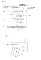
- Fig. 6 illustrates an example of a gain setting screen.
- the digital mixer 100 displays a screen 601 in Fig. 6 .
- the screen 601 where gain setting of three channels ch1 to ch3 is performed is taken as an example.
- the left area of the screen 601 is a gain setting screen for ch1
- 611 is an index display indicating that Vocal is set to ch1 as a category. The similar index is displayed also for each of ch2 and ch3.
- 612 denotes a recommended range
- 613 denotes a meter display
- 614 denotes a display of a knob (a knob control as a GUI, for example) to be touched when gain setting is performed.
- the user desires to perform gain setting of ch1
- the user first touches the knob display 614 to bring ch1 into a selected state and operates a knob (provided on the control panel) being a physical control corresponding to the knob display 614, to thereby perform setting of a gain of the HA 211 of ch1.
- a gesture input to operate the knob display 614 on the gain setting screen is given to the touch panel, and thereby setting of a gain of the HA 211 of ch1 is performed.
- the meter display 613 is a meter to display the level of a signal obtained after level adjustment in the HA 211 of ch1.
- the lower end 641 of a vertically long rectangle corresponds to the level minimum value 501 in Fig. 5 and the upper end 642 thereof corresponds to the level maximum value 502.
- An upper end of a portion painted in gray indicates a present level value (to be called a "meter value").
- the recommended range 612 is a rectangular display indicating the dynamic range corresponding to the musical instrument type of the category set for ch1.
- the lower end 651 corresponds to the position of the recommended minimum value 511 in Fig. 5 and the upper end 652 corresponds to the position of the recommended maximum value 512 in Fig. 5 .
- the digital mixer 100 reads out the recommended minimum value 414 and the recommended maximum value 415 of the category information 400 of Vocal, and based on a scale from the minimum value 641 to the maximum value 642 of the meter display 613, determines the position of the lower end 651 and the position of the upper end 652 according to the values of the recommended minimum value 414 and the recommended maximum value 415, displays the rectangle of the recommended range 612.
- a recommended range 622 representing the range of the dynamic range 520 of the category of Synth is displayed
- a recommended range 632 representing the range of the dynamic range 530 of the category of Kick is displayed.
- the mixer 100 meter-displays the level of a level-adjusted signal based on the recommended range of the level in the category set for each of the channels.
- Fig. 7 is a graph illustrating a display image of the meter (for example, 641) on the gain setting screen.
- the horizontal axis indicates time and the vertical axis indicates a signal level.
- the user can select a mode in which a level value of an actual input signal itself is displayed as a meter value, which is called decay mode off, or a mode in which a level value of an actual input signal is decayed to be displayed as a meter value, which is called decay mode on.
- An operation for the above selection is arbitrary.
- a dotted line 701 is a graph illustrating a change in the level value of the actual input signal.
- the level value of the dotted line 701 itself is displayed as a meter value.
- the meter value also fluctuates suddenly with the change.
- the user sometimes has difficulty in viewing a fluctuation amplitude of the meter value.
- decay mode on is to be applied.
- a solid line 702 is a graph illustrating a change in the meter value in the case of decay mode on.
- Fig. 8 and Fig. 9 illustrate a different example of the meter display.
- This example is an example where only the recommended range of the level of each category is scaled to be meter-displayed.
- the rectangles of Vocal, Synth, and Kick in Fig. 8 indicate the recommended ranges of the individual categories, and are the same ones as those in Fig. 5 .
- the same numbers are added to the same ones in Fig. 5 and in Fig. 8 .
- dynamic ranges 510, 520, 530, ⁇ being the recommended ranges of the individual categories are scaled (mapped) and when each signal level falls within these ranges, the meter display is performed.
- each of the dynamic ranges is scaled to a predetermined number of segments and a light/lights of the segment/segments according to the signal level is/are turned on.
- the segment is a single small rectangular area capable of lighting display (one simulated a lighting LED) and light-out display (one simulated an unlighted LED).
- the dynamic range 510 is equally divided into five divided sections and the individual divided sections are made to correspond to five segments 801 in order.
- the dynamic range 520 and the range of the dynamic range 530 are each equally divided into five divided sections, and the individual divided sections are made to correspond to five segments in order.
- Fig. 9 illustrates an example of the gain setting screen of the case when scaling is performed as illustrated in Fig. 8 .
- a screen 901 is displayed according to a predetermined operation of the user.
- the screen for the single channel ch1 is illustrated.
- screens for a plurality of channels may also be displayed.
- 903 is the same display as the index display 611 in Fig. 6 .
- 905 is a display of a knob, which is the same as the knob display 614 in Fig. 6 , to be touched to select a channel whose gain setting is performed.
- the dynamic range 510 is equally divided into five sections, and the individual divided sections correspond to the five segments 904-1 to 904-5 in order respectively.
- the signal level obtained after level adjustment in the HA 211 is in the head divided section 510-1 of the dynamic range 510, for example, a light of the corresponding segment 904-1 is turned on and lights of the other segments are turned off.
- the signal level obtained after level adjustment in the HA 211 is in the second divided section 510-2
- a light of the corresponding segment 904-2 is turned on and lights of the other segments are turned off.
- lights of all the five segments 904 are turned off.
- the mixer 100 meter-displays the level of a level-adjusted signal based on the recommended range of the level in the category set for each of the channels.
- the recommended ranges are scaled into the same number of segments, and thereby there is an advantage that the user can perform gain adjustment in any category in the same sense.
- the level value of an input signal is decayed to be meter-displayed as has been explained in Fig. 7 .
- Fig. 10 is a flowchart of a gain setting process executed by the CPU 101. This processing is started in response to a user's predetermined operation to give an instruction of gain setting. It is assumed that a channel to be subjected to the gain setting process and a category set for the channel are already specified when this processing is started.
- the CPU 101 obtains the category information 400 of the category set for the channel being a processing target, and at step 1002, obtains the recommended minimum value 414 and the recommended maximum value 415 from the category information 400.
- the CPU 101 determines whether to apply the screen illustrated in Fig. 9 where scaling is performed or the screen illustrated in Fig. 6 where scaling is not performed. It is assumed that which screen to apply is specified by the user beforehand. In the case when scaling is not performed, at step 1004, the CPU displays the gain setting screen such as Fig. 6 (including objects other than the recommended ranges and the meter displays). Next, at step 1005, the CPU 101 displays the recommended range (612 in Fig. 6 or the like) according to the recommended minimum value 414 and the recommended maximum value 415 obtained at step 1002. At step 1006, the CPU 101 sets the meter area (613 in Fig. 6 or the like). When scaling is performed at step 1003, at step 1007, the CPU 101 displays the gain setting screen such as Fig. 9 (including objects other than the meter display). At step 1008, the CPU 101 scales set the meter area (904 in Fig. 9 ) scaled according to the recommended minimum value 414 and the recommended maximum value 415 obtained at step 1002.
- the CPU 101 determines whether or not to make decay reflected on the meter display. It is assumed that whether or not to decay a meter value is specified by the user beforehand. When the meter value is not to be decayed, the CPU 101 applies the decay mode off at step 1010, and when a meter value is to be decayed, the CPU 101 applies the decay mode on at step 1011.
- Steps 1012 to 1015 are loop processing for repeatedly performing the meter display on the gain setting screen.
- this loop processing ends.
- a process of detecting an operation to a knob to perform gain setting of a channel being a processing target and supplying a gain value according to the detected operation to the HA 211 is executed repeatedly.
- a the CPU 101 obtains level value of a metering point of the channel being a processing target. Level value of the signal after level adjustment in the HA 211 is obtained here.
- the CPU 101 updates the meter display according to the level value. Incidentally, in the case of decay mode on, the CPU 101 decays the meter value according to the decay value 416 in the category information 400 obtained at step 1001.
- the meter display and the recommended range are displayed in rectangles different from each other, but it is also possible that the recommended range is displayed on the meter display itself with a different display color.
- the meter, display and the recommended range are each displayed with a rectangle long in the vertical direction, but they may also be positioned in the lateral direction.
- the meter display is expressed by the five segments aligned in the lateral direction, but the number of segments is not limited to this, and further the alignment direction may also be the vertical direction.
- the decay value 416 is provided in each category, but a single decay value common to all the categories may also be used.
- the gain information 411 in the category information 400 may be factory preset beforehand, or may also be changed by the user.
- whether or not to perform scaling may be fixedly determined beforehand.
- the processing at step 1003 may be omitted and either the process of step 1004 to step 1006 or the process of step 1007 and step 1008 should be executed.
- whether or not the decay is to be effective may also be fixedly determined beforehand.
- the process of steps 1009, 1010, and 1011 may be omitted and at step 1014, the display of the meter area may be updated in the decay mode determined beforehand.
- This embodiment is one in which the present invention is applied to the digital mixer 100, but the embodiment of the present invention is not limited to this and is applicable to various embodiments without departing from the technical idea of the present invention.
- software realizing the present invention is installed in a general-purpose information terminal (a PC, a smartphone, or the like) and the software is executed, to thereby enable the information terminal to function as the signal processing device of the present invention.
- software realizing the present invention is provided as an online service and a general-purpose information terminal accesses the service, to thereby function as the signal processing device of the present invention as a whole.
Landscapes
- Engineering & Computer Science (AREA)
- Multimedia (AREA)
- Theoretical Computer Science (AREA)
- Signal Processing (AREA)
- Human Computer Interaction (AREA)
- General Health & Medical Sciences (AREA)
- Audiology, Speech & Language Pathology (AREA)
- Physics & Mathematics (AREA)
- General Engineering & Computer Science (AREA)
- General Physics & Mathematics (AREA)
- Health & Medical Sciences (AREA)
- Circuit For Audible Band Transducer (AREA)
- Control Of Amplification And Gain Control (AREA)
- Indication And Recording Devices For Special Purposes And Tariff Metering Devices (AREA)
- Circuits Of Receivers In General (AREA)
Applications Claiming Priority (1)
| Application Number | Priority Date | Filing Date | Title |
|---|---|---|---|
| JP2014060924A JP6319653B2 (ja) | 2014-03-24 | 2014-03-24 | 信号処理装置およびプログラム |
Publications (3)
| Publication Number | Publication Date |
|---|---|
| EP2924898A2 true EP2924898A2 (de) | 2015-09-30 |
| EP2924898A3 EP2924898A3 (de) | 2015-11-04 |
| EP2924898B1 EP2924898B1 (de) | 2022-05-04 |
Family
ID=53175247
Family Applications (1)
| Application Number | Title | Priority Date | Filing Date |
|---|---|---|---|
| EP15160450.1A Active EP2924898B1 (de) | 2014-03-24 | 2015-03-24 | Signalverarbeitungsvorrichtung und computerprogramm für signalverarbeitung |
Country Status (3)
| Country | Link |
|---|---|
| US (1) | US9858035B2 (de) |
| EP (1) | EP2924898B1 (de) |
| JP (1) | JP6319653B2 (de) |
Families Citing this family (2)
| Publication number | Priority date | Publication date | Assignee | Title |
|---|---|---|---|---|
| CN109889890A (zh) * | 2019-03-15 | 2019-06-14 | 青岛海信电器股份有限公司 | 音频数据的处理方法和装置 |
| JP2021132350A (ja) * | 2020-02-21 | 2021-09-09 | ヤマハ株式会社 | 音響処理方法、パラメータ設定装置及び音響処理プログラム |
Family Cites Families (14)
| Publication number | Priority date | Publication date | Assignee | Title |
|---|---|---|---|---|
| JPH05275945A (ja) * | 1992-03-25 | 1993-10-22 | Sony Corp | デジタルオーディオ信号のレベル表示装置 |
| JPH08125466A (ja) * | 1994-10-27 | 1996-05-17 | Toa Corp | オーディオミキサー |
| JP3821243B2 (ja) * | 1995-11-13 | 2006-09-13 | 株式会社タムラ製作所 | ミキシングコンソールのパラメータ再現装置 |
| US6804827B1 (en) | 1998-09-18 | 2004-10-12 | Sony Corporation | Transmission system and method signal adjusting apparatus and method and routing apparatus |
| JP3823631B2 (ja) * | 1999-09-01 | 2006-09-20 | ヤマハ株式会社 | ディジタルミキサー装置 |
| JP3951655B2 (ja) * | 2001-09-21 | 2007-08-01 | ヤマハ株式会社 | 操作子の表示装置 |
| JP3812837B2 (ja) | 2003-02-26 | 2006-08-23 | ソニー株式会社 | 音量調節装置、音量調節方法及びテレビジョン装置 |
| JP2005070545A (ja) * | 2003-08-26 | 2005-03-17 | Sony Corp | 記録媒体、情報処理方法、情報処理プログラムおよび情報機器 |
| US7725826B2 (en) | 2004-03-26 | 2010-05-25 | Harman International Industries, Incorporated | Audio-related system node instantiation |
| US7694230B2 (en) * | 2005-09-09 | 2010-04-06 | Yamaha Corporation | Digital mixer and program |
| KR101137361B1 (ko) * | 2009-01-28 | 2012-04-26 | 엘지전자 주식회사 | 오디오 신호 처리 방법 및 장치 |
| WO2010087631A2 (en) * | 2009-01-28 | 2010-08-05 | Lg Electronics Inc. | A method and an apparatus for decoding an audio signal |
| JP5434784B2 (ja) * | 2010-05-06 | 2014-03-05 | ヤマハ株式会社 | ミキシング装置 |
| US8989406B2 (en) * | 2011-03-11 | 2015-03-24 | Sony Corporation | User profile based audio adjustment techniques |
-
2014
- 2014-03-24 JP JP2014060924A patent/JP6319653B2/ja active Active
-
2015
- 2015-03-17 US US14/660,788 patent/US9858035B2/en active Active
- 2015-03-24 EP EP15160450.1A patent/EP2924898B1/de active Active
Non-Patent Citations (1)
| Title |
|---|
| "DIGITAL MIXING CONSOLE M7CL, User's manual", 2005, YAMAHA CORPORATION |
Also Published As
| Publication number | Publication date |
|---|---|
| JP2015186046A (ja) | 2015-10-22 |
| US20150268923A1 (en) | 2015-09-24 |
| US9858035B2 (en) | 2018-01-02 |
| JP6319653B2 (ja) | 2018-05-09 |
| EP2924898B1 (de) | 2022-05-04 |
| EP2924898A3 (de) | 2015-11-04 |
Similar Documents
| Publication | Publication Date | Title |
|---|---|---|
| CN107562402B (zh) | 控制音频信号参数 | |
| US11195501B2 (en) | Systems and methods for generating musical tempo gridlines on an electronic drum module display | |
| US9160294B2 (en) | Virtual pre-amplifier and effects system and methods for customizing and using the same in live performances | |
| US20140149911A1 (en) | Electronic musical instrument and application for same | |
| CN113286231A (zh) | 音频信号处理装置、音频系统和音频信号处理方法 | |
| US9858035B2 (en) | Signal processing device and storage medium | |
| US9573049B2 (en) | Strum pad | |
| US11211039B2 (en) | Musical instrument tuning | |
| KR101605496B1 (ko) | 악기 튜닝 기능을 구비한 음악 반주 장치 | |
| JP6520162B2 (ja) | 伴奏教習装置および伴奏教習プログラム | |
| US20160274858A1 (en) | Displaying attenuating audio signal level in delayed fashion | |
| US20160299677A1 (en) | Equalizer setting device, equalizer setting method, medium storing equalizer setting program | |
| JP6634687B2 (ja) | レベル制御装置 | |
| JP2011239019A (ja) | ミキシング装置 | |
| JP2016174257A (ja) | レベル制御装置 | |
| CN100381988C (zh) | 用于调节控制参数的组合的系统 | |
| CN110874171B (zh) | 音频信息处理方法及装置 | |
| JP2017073631A (ja) | 音信号処理装置用設定プログラム | |
| JP5035090B2 (ja) | 制御装置 | |
| JP5135930B2 (ja) | 楽曲加工装置およびプログラム | |
| CN116645940A (zh) | 输入装置及电子乐器 | |
| JP6784588B2 (ja) | 楽譜表示・演奏プログラム | |
| WO2019026262A1 (ja) | 楽譜表示装置、楽譜表示方法および楽譜表示プログラム | |
| JP2015049470A (ja) | 信号処理装置及びそのプログラム | |
| US20240185820A1 (en) | Electronic tempo trainer |
Legal Events
| Date | Code | Title | Description |
|---|---|---|---|
| PUAI | Public reference made under article 153(3) epc to a published international application that has entered the european phase |
Free format text: ORIGINAL CODE: 0009012 |
|
| AK | Designated contracting states |
Kind code of ref document: A2 Designated state(s): AL AT BE BG CH CY CZ DE DK EE ES FI FR GB GR HR HU IE IS IT LI LT LU LV MC MK MT NL NO PL PT RO RS SE SI SK SM TR |
|
| AX | Request for extension of the european patent |
Extension state: BA ME |
|
| PUAL | Search report despatched |
Free format text: ORIGINAL CODE: 0009013 |
|
| AK | Designated contracting states |
Kind code of ref document: A3 Designated state(s): AL AT BE BG CH CY CZ DE DK EE ES FI FR GB GR HR HU IE IS IT LI LT LU LV MC MK MT NL NO PL PT RO RS SE SI SK SM TR |
|
| AX | Request for extension of the european patent |
Extension state: BA ME |
|
| RIC1 | Information provided on ipc code assigned before grant |
Ipc: H04H 60/04 20080101AFI20150930BHEP |
|
| 17P | Request for examination filed |
Effective date: 20160504 |
|
| RBV | Designated contracting states (corrected) |
Designated state(s): AL AT BE BG CH CY CZ DE DK EE ES FI FR GB GR HR HU IE IS IT LI LT LU LV MC MK MT NL NO PL PT RO RS SE SI SK SM TR |
|
| STAA | Information on the status of an ep patent application or granted ep patent |
Free format text: STATUS: EXAMINATION IS IN PROGRESS |
|
| 17Q | First examination report despatched |
Effective date: 20190214 |
|
| GRAP | Despatch of communication of intention to grant a patent |
Free format text: ORIGINAL CODE: EPIDOSNIGR1 |
|
| STAA | Information on the status of an ep patent application or granted ep patent |
Free format text: STATUS: GRANT OF PATENT IS INTENDED |
|
| INTG | Intention to grant announced |
Effective date: 20220105 |
|
| GRAS | Grant fee paid |
Free format text: ORIGINAL CODE: EPIDOSNIGR3 |
|
| GRAA | (expected) grant |
Free format text: ORIGINAL CODE: 0009210 |
|
| STAA | Information on the status of an ep patent application or granted ep patent |
Free format text: STATUS: THE PATENT HAS BEEN GRANTED |
|
| AK | Designated contracting states |
Kind code of ref document: B1 Designated state(s): AL AT BE BG CH CY CZ DE DK EE ES FI FR GB GR HR HU IE IS IT LI LT LU LV MC MK MT NL NO PL PT RO RS SE SI SK SM TR |
|
| REG | Reference to a national code |
Ref country code: GB Ref legal event code: FG4D |
|
| REG | Reference to a national code |
Ref country code: CH Ref legal event code: EP |
|
| REG | Reference to a national code |
Ref country code: AT Ref legal event code: REF Ref document number: 1490260 Country of ref document: AT Kind code of ref document: T Effective date: 20220515 |
|
| REG | Reference to a national code |
Ref country code: IE Ref legal event code: FG4D Ref country code: DE Ref legal event code: R096 Ref document number: 602015078623 Country of ref document: DE |
|
| REG | Reference to a national code |
Ref country code: LT Ref legal event code: MG9D |
|
| REG | Reference to a national code |
Ref country code: NL Ref legal event code: MP Effective date: 20220504 |
|
| REG | Reference to a national code |
Ref country code: AT Ref legal event code: MK05 Ref document number: 1490260 Country of ref document: AT Kind code of ref document: T Effective date: 20220504 |
|
| PG25 | Lapsed in a contracting state [announced via postgrant information from national office to epo] |
Ref country code: SE Free format text: LAPSE BECAUSE OF FAILURE TO SUBMIT A TRANSLATION OF THE DESCRIPTION OR TO PAY THE FEE WITHIN THE PRESCRIBED TIME-LIMIT Effective date: 20220504 Ref country code: PT Free format text: LAPSE BECAUSE OF FAILURE TO SUBMIT A TRANSLATION OF THE DESCRIPTION OR TO PAY THE FEE WITHIN THE PRESCRIBED TIME-LIMIT Effective date: 20220905 Ref country code: NO Free format text: LAPSE BECAUSE OF FAILURE TO SUBMIT A TRANSLATION OF THE DESCRIPTION OR TO PAY THE FEE WITHIN THE PRESCRIBED TIME-LIMIT Effective date: 20220804 Ref country code: NL Free format text: LAPSE BECAUSE OF FAILURE TO SUBMIT A TRANSLATION OF THE DESCRIPTION OR TO PAY THE FEE WITHIN THE PRESCRIBED TIME-LIMIT Effective date: 20220504 Ref country code: LT Free format text: LAPSE BECAUSE OF FAILURE TO SUBMIT A TRANSLATION OF THE DESCRIPTION OR TO PAY THE FEE WITHIN THE PRESCRIBED TIME-LIMIT Effective date: 20220504 Ref country code: HR Free format text: LAPSE BECAUSE OF FAILURE TO SUBMIT A TRANSLATION OF THE DESCRIPTION OR TO PAY THE FEE WITHIN THE PRESCRIBED TIME-LIMIT Effective date: 20220504 Ref country code: GR Free format text: LAPSE BECAUSE OF FAILURE TO SUBMIT A TRANSLATION OF THE DESCRIPTION OR TO PAY THE FEE WITHIN THE PRESCRIBED TIME-LIMIT Effective date: 20220805 Ref country code: FI Free format text: LAPSE BECAUSE OF FAILURE TO SUBMIT A TRANSLATION OF THE DESCRIPTION OR TO PAY THE FEE WITHIN THE PRESCRIBED TIME-LIMIT Effective date: 20220504 Ref country code: ES Free format text: LAPSE BECAUSE OF FAILURE TO SUBMIT A TRANSLATION OF THE DESCRIPTION OR TO PAY THE FEE WITHIN THE PRESCRIBED TIME-LIMIT Effective date: 20220504 Ref country code: BG Free format text: LAPSE BECAUSE OF FAILURE TO SUBMIT A TRANSLATION OF THE DESCRIPTION OR TO PAY THE FEE WITHIN THE PRESCRIBED TIME-LIMIT Effective date: 20220804 Ref country code: AT Free format text: LAPSE BECAUSE OF FAILURE TO SUBMIT A TRANSLATION OF THE DESCRIPTION OR TO PAY THE FEE WITHIN THE PRESCRIBED TIME-LIMIT Effective date: 20220504 |
|
| PG25 | Lapsed in a contracting state [announced via postgrant information from national office to epo] |
Ref country code: RS Free format text: LAPSE BECAUSE OF FAILURE TO SUBMIT A TRANSLATION OF THE DESCRIPTION OR TO PAY THE FEE WITHIN THE PRESCRIBED TIME-LIMIT Effective date: 20220504 Ref country code: PL Free format text: LAPSE BECAUSE OF FAILURE TO SUBMIT A TRANSLATION OF THE DESCRIPTION OR TO PAY THE FEE WITHIN THE PRESCRIBED TIME-LIMIT Effective date: 20220504 Ref country code: LV Free format text: LAPSE BECAUSE OF FAILURE TO SUBMIT A TRANSLATION OF THE DESCRIPTION OR TO PAY THE FEE WITHIN THE PRESCRIBED TIME-LIMIT Effective date: 20220504 Ref country code: IS Free format text: LAPSE BECAUSE OF FAILURE TO SUBMIT A TRANSLATION OF THE DESCRIPTION OR TO PAY THE FEE WITHIN THE PRESCRIBED TIME-LIMIT Effective date: 20220904 |
|
| PG25 | Lapsed in a contracting state [announced via postgrant information from national office to epo] |
Ref country code: SM Free format text: LAPSE BECAUSE OF FAILURE TO SUBMIT A TRANSLATION OF THE DESCRIPTION OR TO PAY THE FEE WITHIN THE PRESCRIBED TIME-LIMIT Effective date: 20220504 Ref country code: SK Free format text: LAPSE BECAUSE OF FAILURE TO SUBMIT A TRANSLATION OF THE DESCRIPTION OR TO PAY THE FEE WITHIN THE PRESCRIBED TIME-LIMIT Effective date: 20220504 Ref country code: RO Free format text: LAPSE BECAUSE OF FAILURE TO SUBMIT A TRANSLATION OF THE DESCRIPTION OR TO PAY THE FEE WITHIN THE PRESCRIBED TIME-LIMIT Effective date: 20220504 Ref country code: EE Free format text: LAPSE BECAUSE OF FAILURE TO SUBMIT A TRANSLATION OF THE DESCRIPTION OR TO PAY THE FEE WITHIN THE PRESCRIBED TIME-LIMIT Effective date: 20220504 Ref country code: DK Free format text: LAPSE BECAUSE OF FAILURE TO SUBMIT A TRANSLATION OF THE DESCRIPTION OR TO PAY THE FEE WITHIN THE PRESCRIBED TIME-LIMIT Effective date: 20220504 Ref country code: CZ Free format text: LAPSE BECAUSE OF FAILURE TO SUBMIT A TRANSLATION OF THE DESCRIPTION OR TO PAY THE FEE WITHIN THE PRESCRIBED TIME-LIMIT Effective date: 20220504 |
|
| REG | Reference to a national code |
Ref country code: DE Ref legal event code: R097 Ref document number: 602015078623 Country of ref document: DE |
|
| PLBE | No opposition filed within time limit |
Free format text: ORIGINAL CODE: 0009261 |
|
| STAA | Information on the status of an ep patent application or granted ep patent |
Free format text: STATUS: NO OPPOSITION FILED WITHIN TIME LIMIT |
|
| PG25 | Lapsed in a contracting state [announced via postgrant information from national office to epo] |
Ref country code: AL Free format text: LAPSE BECAUSE OF FAILURE TO SUBMIT A TRANSLATION OF THE DESCRIPTION OR TO PAY THE FEE WITHIN THE PRESCRIBED TIME-LIMIT Effective date: 20220504 |
|
| 26N | No opposition filed |
Effective date: 20230207 |
|
| PG25 | Lapsed in a contracting state [announced via postgrant information from national office to epo] |
Ref country code: SI Free format text: LAPSE BECAUSE OF FAILURE TO SUBMIT A TRANSLATION OF THE DESCRIPTION OR TO PAY THE FEE WITHIN THE PRESCRIBED TIME-LIMIT Effective date: 20220504 |
|
| PG25 | Lapsed in a contracting state [announced via postgrant information from national office to epo] |
Ref country code: MC Free format text: LAPSE BECAUSE OF FAILURE TO SUBMIT A TRANSLATION OF THE DESCRIPTION OR TO PAY THE FEE WITHIN THE PRESCRIBED TIME-LIMIT Effective date: 20220504 |
|
| REG | Reference to a national code |
Ref country code: CH Ref legal event code: PL |
|
| GBPC | Gb: european patent ceased through non-payment of renewal fee |
Effective date: 20230324 |
|
| REG | Reference to a national code |
Ref country code: BE Ref legal event code: MM Effective date: 20230331 |
|
| PG25 | Lapsed in a contracting state [announced via postgrant information from national office to epo] |
Ref country code: LU Free format text: LAPSE BECAUSE OF NON-PAYMENT OF DUE FEES Effective date: 20230324 |
|
| REG | Reference to a national code |
Ref country code: IE Ref legal event code: MM4A |
|
| PG25 | Lapsed in a contracting state [announced via postgrant information from national office to epo] |
Ref country code: GB Free format text: LAPSE BECAUSE OF NON-PAYMENT OF DUE FEES Effective date: 20230324 |
|
| PG25 | Lapsed in a contracting state [announced via postgrant information from national office to epo] |
Ref country code: LI Free format text: LAPSE BECAUSE OF NON-PAYMENT OF DUE FEES Effective date: 20230331 Ref country code: IT Free format text: LAPSE BECAUSE OF FAILURE TO SUBMIT A TRANSLATION OF THE DESCRIPTION OR TO PAY THE FEE WITHIN THE PRESCRIBED TIME-LIMIT Effective date: 20220504 Ref country code: IE Free format text: LAPSE BECAUSE OF NON-PAYMENT OF DUE FEES Effective date: 20230324 Ref country code: GB Free format text: LAPSE BECAUSE OF NON-PAYMENT OF DUE FEES Effective date: 20230324 Ref country code: FR Free format text: LAPSE BECAUSE OF NON-PAYMENT OF DUE FEES Effective date: 20230331 Ref country code: CH Free format text: LAPSE BECAUSE OF NON-PAYMENT OF DUE FEES Effective date: 20230331 |
|
| PG25 | Lapsed in a contracting state [announced via postgrant information from national office to epo] |
Ref country code: BE Free format text: LAPSE BECAUSE OF NON-PAYMENT OF DUE FEES Effective date: 20230331 |
|
| PG25 | Lapsed in a contracting state [announced via postgrant information from national office to epo] |
Ref country code: BG Free format text: LAPSE BECAUSE OF FAILURE TO SUBMIT A TRANSLATION OF THE DESCRIPTION OR TO PAY THE FEE WITHIN THE PRESCRIBED TIME-LIMIT Effective date: 20220504 |
|
| PG25 | Lapsed in a contracting state [announced via postgrant information from national office to epo] |
Ref country code: BG Free format text: LAPSE BECAUSE OF FAILURE TO SUBMIT A TRANSLATION OF THE DESCRIPTION OR TO PAY THE FEE WITHIN THE PRESCRIBED TIME-LIMIT Effective date: 20220504 |
|
| PG25 | Lapsed in a contracting state [announced via postgrant information from national office to epo] |
Ref country code: CY Free format text: LAPSE BECAUSE OF FAILURE TO SUBMIT A TRANSLATION OF THE DESCRIPTION OR TO PAY THE FEE WITHIN THE PRESCRIBED TIME-LIMIT; INVALID AB INITIO Effective date: 20150324 |
|
| PG25 | Lapsed in a contracting state [announced via postgrant information from national office to epo] |
Ref country code: HU Free format text: LAPSE BECAUSE OF FAILURE TO SUBMIT A TRANSLATION OF THE DESCRIPTION OR TO PAY THE FEE WITHIN THE PRESCRIBED TIME-LIMIT; INVALID AB INITIO Effective date: 20150324 |
|
| PG25 | Lapsed in a contracting state [announced via postgrant information from national office to epo] |
Ref country code: TR Free format text: LAPSE BECAUSE OF FAILURE TO SUBMIT A TRANSLATION OF THE DESCRIPTION OR TO PAY THE FEE WITHIN THE PRESCRIBED TIME-LIMIT Effective date: 20220504 |
|
| PGFP | Annual fee paid to national office [announced via postgrant information from national office to epo] |
Ref country code: DE Payment date: 20260319 Year of fee payment: 12 |