EP2924409B1 - Drucksensor mit Überdruckschutz - Google Patents
Drucksensor mit Überdruckschutz Download PDFInfo
- Publication number
- EP2924409B1 EP2924409B1 EP15158319.2A EP15158319A EP2924409B1 EP 2924409 B1 EP2924409 B1 EP 2924409B1 EP 15158319 A EP15158319 A EP 15158319A EP 2924409 B1 EP2924409 B1 EP 2924409B1
- Authority
- EP
- European Patent Office
- Prior art keywords
- diaphragm
- sense
- stop
- pressure sensor
- projections
- Prior art date
- Legal status (The legal status is an assumption and is not a legal conclusion. Google has not performed a legal analysis and makes no representation as to the accuracy of the status listed.)
- Active
Links
Images





Classifications
-
- G—PHYSICS
- G01—MEASURING; TESTING
- G01L—MEASURING FORCE, STRESS, TORQUE, WORK, MECHANICAL POWER, MECHANICAL EFFICIENCY, OR FLUID PRESSURE
- G01L7/00—Measuring the steady or quasi-steady pressure of a fluid or a fluent solid material by mechanical or fluid pressure-sensitive elements
- G01L7/02—Measuring the steady or quasi-steady pressure of a fluid or a fluent solid material by mechanical or fluid pressure-sensitive elements in the form of elastically-deformable gauges
- G01L7/08—Measuring the steady or quasi-steady pressure of a fluid or a fluent solid material by mechanical or fluid pressure-sensitive elements in the form of elastically-deformable gauges of the flexible-diaphragm type
-
- G—PHYSICS
- G01—MEASURING; TESTING
- G01L—MEASURING FORCE, STRESS, TORQUE, WORK, MECHANICAL POWER, MECHANICAL EFFICIENCY, OR FLUID PRESSURE
- G01L13/00—Devices or apparatus for measuring differences of two or more fluid pressure values
- G01L13/02—Devices or apparatus for measuring differences of two or more fluid pressure values using elastically-deformable members or pistons as sensing elements
- G01L13/025—Devices or apparatus for measuring differences of two or more fluid pressure values using elastically-deformable members or pistons as sensing elements using diaphragms
-
- G—PHYSICS
- G01—MEASURING; TESTING
- G01L—MEASURING FORCE, STRESS, TORQUE, WORK, MECHANICAL POWER, MECHANICAL EFFICIENCY, OR FLUID PRESSURE
- G01L19/00—Details of, or accessories for, apparatus for measuring steady or quasi-steady pressure of a fluent medium insofar as such details or accessories are not special to particular types of pressure gauges
- G01L19/06—Means for preventing overload or deleterious influence of the measured medium on the measuring device or vice versa
- G01L19/0618—Overload protection
-
- G—PHYSICS
- G01—MEASURING; TESTING
- G01L—MEASURING FORCE, STRESS, TORQUE, WORK, MECHANICAL POWER, MECHANICAL EFFICIENCY, OR FLUID PRESSURE
- G01L9/00—Measuring steady of quasi-steady pressure of fluid or fluent solid material by electric or magnetic pressure-sensitive elements; Transmitting or indicating the displacement of mechanical pressure-sensitive elements, used to measure the steady or quasi-steady pressure of a fluid or fluent solid material, by electric or magnetic means
- G01L9/0041—Transmitting or indicating the displacement of flexible diaphragms
- G01L9/0042—Constructional details associated with semiconductive diaphragm sensors, e.g. etching, or constructional details of non-semiconductive diaphragms
- G01L9/0045—Diaphragm associated with a buried cavity
-
- G—PHYSICS
- G01—MEASURING; TESTING
- G01L—MEASURING FORCE, STRESS, TORQUE, WORK, MECHANICAL POWER, MECHANICAL EFFICIENCY, OR FLUID PRESSURE
- G01L9/00—Measuring steady of quasi-steady pressure of fluid or fluent solid material by electric or magnetic pressure-sensitive elements; Transmitting or indicating the displacement of mechanical pressure-sensitive elements, used to measure the steady or quasi-steady pressure of a fluid or fluent solid material, by electric or magnetic means
- G01L9/0041—Transmitting or indicating the displacement of flexible diaphragms
- G01L9/0051—Transmitting or indicating the displacement of flexible diaphragms using variations in ohmic resistance
Definitions
- the present disclosure relates generally to sensors, and more particularly, to pressure sensors.
- Pressure sensors often include a pressure sense element that is configured to detect a pressure of a media to be sensed by converting mechanical stress caused by the incoming pressure of the media into an electrical output signal. Pressure measurements are typically taken in the context of absolute, gauge, or differential (or relative) pressure measurements.
- An absolute pressure sensor represents a specific type of sensing device, which measures a pressure relative to a vacuum (or a sealed reference).
- a gauge sensor measures a pressure relative to atmospheric pressure.
- a differential pressure sensor measures a pressure difference between two input pressures.
- Patent document number US2006/272422A1 describes a pressure sensor device having a laminated diaphragm in which a strain resistance gauge is formed in a surface and a stopper member including a concave portion forming a curved surface parallel to a surface formed by displacement of the diaphragm. The concave portion is disposed to face the diaphragm.
- Patent document number WO2013/060697A1 describes a micromechanical structure for measuring or detecting a mechanical quantity or a dynamic quantity, including a deformable membrane and a supporting substrate.
- the membrane includes a first portion and a second portion surrounded by the first portion. The second portion has a thickness that is less than the thickness of the first portion.
- the membrane is suspended above the supporting substrate and thus defines a free space.
- the micromechanical structure comprises in addition a lower abutment for limiting the deformations of the membrane.
- the lower abutment is arranged above the supporting substrate and extends into the free space from the supporting substrate toward the membrane.
- the lower abutment comprises islets that extend into the free space toward the membrane from a flat surface of the lower abutment.
- the islets form a relief structure in such a manner that, in the case of contact between the islets and the fine portion of the membrane, the contact surface between the islets and the fine portion of the membrane is small with respect to the dimensions of the fine portion of the
- Patent document number US2012/105385A1 describes systems, methods, and apparatus for producing roughness in an electromechanical device by nucleation under plasma CVD conditions.
- a substrate and at least a first layer are provided.
- the disclosure further provides gas phase nucleating particles under plasma CVD conditions and depositing a first layer, where the particles are incorporated into the first layer to create roughness in the first layer.
- the roughness may be transferred to a second layer by conformal deposition of the second layer over the first layer.
- the roughness of the second layer corresponds to the roughness of the first layer, where the first layer has a roughness greater than or equal to about 20 not a root mean square (RMS).
- RMS root mean square
- This disclosure relates generally to sensors, and more particularly, to sensors that may be exposed to overpressure during use.
- sensor assemblies are known to exist, there is need for improvement to such sensor assemblies.
- a pressure sensor may include an input for receiving an input pressure and a sense die having a sense diaphragm that is exposed to the input pressure and is configured to deflect in response to the input pressure.
- One or more sense elements may be operatively coupled to the sense diaphragm in order to sense deflection of the sense diagram.
- a first diaphragm stop may be positioned adjacent to a first side of the sense diaphragm to limit deflection of the sense diaphragm towards the first diaphragm stop.
- the first diaphragm stop may include a first diaphragm stop surface facing the first side of the sense diaphragm, the first diaphragm stop including a plurality of defined projections.
- a pressure sensor may include an input for receiving an input pressure and a sense die having a first major surface and an opposing second major surface.
- a recess may be provided in the first major surface to form a recessed first surface, wherein a sense diaphragm is defined between the recessed first surface and the second major surface of the sense die.
- the sense diaphragm may be exposed to an input pressure, and may deflect in response to the input pressure.
- One or more sense elements may be operatively coupled to the sense diaphragm to sense the deflection of the sense diaphragm.
- a first substrate may be secured relative to the first major surface of the sense die.
- the first substrate may have a first diaphragm stop that extends away from the substrate and into the recess in the sense die and adjacent to the recessed first surface of the sense diaphragm to limit deflection of the sense diaphragm towards the first diaphragm stop.
- a second substrate may be secured relative to the second major surface of the sense die.
- the second substrate may have a second diaphragm stop that extends adjacent to the second major surface of the sense diaphragm to limit deflection of the sense diaphragm towards the second diaphragm stop.
- a pressure sensor may include an input for receiving an input pressure, and a sense diaphragm exposed to the input pressure and configured to deflect in response to the input pressure.
- One or more sense elements may be operatively coupled to the sense diaphragm to sense the deflection of the sense diaphragm.
- a diaphragm stop may be positioned adjacent to the sense diaphragm to limit deflection of the sense diaphragm.
- the diaphragm stop may have a diaphragm stop surface for engaging the sense diaphragm when the sense diaphragm has deflected by a predefined amount due to the input pressure.
- the diaphragm stop surface may have a topography that is configured to reduce static friction (e.g. stiction) between the diaphragm stop surface and the sense diaphragm relative to a smooth diaphragm stop surface.
- static friction e.g. stiction
- FIG. 1 is a schematic cross-sectional view of an illustrative pressure sensor 10.
- Pressure sensor 10 may include a sense die 12, a base layer 14 and a top layer 16.
- layer here is intended to include any suitable layer(s) or layer combination, including integral layers or separately formed layers such as separately formed substrate(s), die(s), and/or other element(s).
- Sense die 12 may include a sense diaphragm 18 that in some embodiments is defined by a portion of sense die 12 that is thinner than other portions of sense die 12. It will be appreciated that in some embodiments, pressure sensor 10 may include additional layers and/or elements not expressly shown in FIG. 1 . Generally speaking, pressure sensor 10 may be any type of pressure sensor. In one example, pressure sensor 10 may be a pressure sensor such as an absolute pressure sensor, a gauge pressure sensor, a differential pressure sensor, or other pressure sensor as desired. Example pressure sensors may include, but are not limited to, those described in U.S.
- top layer 16 may include a cavity 20 that is constructed with a particular reference pressure. Cavity 20 may include a fluid that is pressurized at the particular reference pressure. Top layer 16 may also include a stop 22 which, as will be discussed in greater detail, can limit upward (in the illustrated orientation) travel of sense diaphragm 18.
- Base layer 14 may include a fluid path 24 that functions as an input port for receiving an input pressure. An input pressure, such as a pressurized fluid media (e.g. liquid or gas), can travel through fluid path 24 and exert a force on sense diaphragm 18.
- a pressurized fluid media e.g. liquid or gas
- sense diaphragm 18 will flex or bend in an upward (in the illustrated orientation) direction. It will be appreciated that reference herein to particular directions such as up and down are illustrative only, as pressure sensor 10 may be used in a variety of different spatial orientations.
- pressure sensor 10 may include one or more sense elements 26 that may be disposed about sense diaphragm 18.
- Sense elements 26 may be any elements that are configured to convert mechanical movement, stress and/or deflection of sense diaphragm 18 into an electrical signal.
- sense elements 26 may be piezo-resistors.
- sense elements 26 may, for example, be arranged in a Wheatstone bridge (e.g. half or full bridge) in order to provide an electrical signal that is indicative of the mechanical deflection of sense diaphragm 18. While two sense elements 26 are shown in the illustrated cross-section of FIG. 1 , it will be appreciated that pressure sensor 10 may include any desired number of sense elements 26. In some embodiments, a total of four sense elements 26 may be arranged in a Full Wheatstone bridge configuration.
- sense diaphragm 18 may be considered as having a perimeter that defines a cross-sectional surface area of sense diaphragm 18.
- Stop 22 may be considered as having a stop surface 23 having a perimeter that defines a cross-sectional area of stop surface 23.
- the cross-sectional area defined by the perimeter of stop surface 23 is between about 10 and 95 percent of the cross-sectional surface area defined by the perimeter of sense diaphragm 18.
- the cross-sectional area defined by the perimeter of stop surface 23 is between 60 and 90 percent of the cross-sectional area defined by the perimeter of sense diaphragm 18.
- the cross-sectional area defined by the perimeter of stop surface 23 is between 60 and 75 percent of the cross-sectional area defined by the perimeter of sense diaphragm 18.
- the elements forming pressure sensor 10 may be formed from any desired and appropriate material.
- sense die 12 may be formed from a silicon material, a material including at least some silicon (e.g., a silicon blend), GaAs, metal, and/or any other material having similar or dissimilar properties.
- Sense diaphragm 18 maybe formed in sense die 12 by, for example, etching, machining, or any other forming technique configured to form sense diaphragm 18 within sense die 12.
- sense elements 26 may be piezoresistive elements made from or include a piezoelectric material and/or one or more other materials that may be configured to change or modify its electrical or other properties in response to a mechanical stress or movement.
- Base layer 14 and top layer 16 may be formed of any suitable material.
- base layer 14 and/or top layer 16 may be at least partially made from a metal material (e.g., a metal material including aluminum, stainless steel, a nickel-cobalt ferrous alloy such as KOVAR®, any other metal material, and/or any combination of metal materials).
- a metal material e.g., a metal material including aluminum, stainless steel, a nickel-cobalt ferrous alloy such as KOVAR®, any other metal material, and/or any combination of metal materials.
- base layer 14 and/or top layer 16 may be entirely made from a metal material, while in other cases, base layer 14 and/or top layer 16 may be coated with a metal material.
- base layer 14 and/or top layer 16 may be at least partially formed of a glass material (e.g., borosilicate glass, such as PYREX®, BOROFLOAT® 33, HOYA SD-2, and/or other borosilicate glass materials, etc.).
- base layer 14 and/or top layer 16 may be at least partially formed of a ceramic material.
- the materials used to form each of sense die 12, base layer 14 and top layer 16 may be selected to be thermally compatible.
- base layer 14 and/or top layer 16 may include two or more distinct layers, each layer being the same material or a different material. Each layer, if present, may be joined using any suitable technique.
- Sense die 12, base layer 14 and top layer 16 may be joined together to form pressure sensor 10 using any desired method or technique. For example, in some embodiments, sense die 12, base layer 14 and top layer 16 may be joined together using anodic bonding, frit bonding, fusing, welding, soldering, an adhesive, or any other suitable bonding, connecting or sealing technique, as desired.
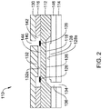
- FIG. 2 provides another illustrative but non-limiting example of pressure sensor 110.
- Pressure sensor 110 is a differential pressure sensor and may include a sense die 112, a base layer 114 and a top layer 116.
- Sense die 112 may include a sense diaphragm 118, which in some embodiments is defined by a portion of sense die 112 that is thinner than other portions of sense die 112. It will be appreciated that in some embodiments, pressure sensor 110 includes additional layers and elements not expressly shown in FIG. 2 .
- pressure sensor 110 may include a constraint layer 146 including a constraint layer stop 128.
- Constraint layer stop 128 may be formed as a raised portion of constraint layer 146 and may extend upward (in the illustrated orientation) towards sense diaphragm 118. As will be discussed, constraint layer stop 128 may limit downward flexing, bending or other movement of sense diaphragm 118.
- the constraint layer stop 128 is formed integral with the constraint layer 146, while in other cases the constraint layer stop 128 is formed separate from the constraint layer 146 and attached to the constraint layer 146.
- the constraint layer stop 128 is formed from or includes a different material than the constraint layer 146.
- Pressure sensor 110 may also include a stop layer 130 including a top stop 132.
- Top stop 132 may be formed as a projection extending downward (in the illustrated orientation) towards sense diaphragm 118. As will be discussed, top stop 132 may limit upward flexing, bending or other movement of sense diaphragm 118.
- the top stop 132 is formed integral with the stop layer 130, while in other cases the top stop 132 is formed separate from the stop layer 130 and attached to the stop layer 130. In some instances, the top stop 132 is formed from or includes a different material than the stop layer 130.
- pressure sensor 110 includes several fluid paths that may be configured to provide a first pressure input and a second pressure input, and thus pressure sensor 110 can measure a relative difference between the first and second pressure inputs, or a differential pressure.
- Base layer 114 includes a fluid path 134 and constraint layer 146 includes a fluid path 136 that is fluidly coupled to fluid path 134 such that fluid path 134 and fluid path 136 in combination provide an input port to a first side 138 of the sense diaphragm 118.
- stop layer 130 includes a fluid path 140 that extends through stop layer 130 and is fluidly coupled with a fluid path 142 such that fluid path 140 and fluid path 142 in combination provide an input port to a second side 144 of the sense diaphragm 118.
- sense diaphragm 118 may bend, flex, deform, or otherwise move in an upward (in the illustrated orientation) direction if an input pressure impinging on first side 138 of sense diaphragm 118 is higher than an input pressure impinging on second side 144 of sense diaphragm 118. If sense diaphragm 118 moves far enough, sense diaphragm 118 will contact a stop surface 132a of top stop 132 such that top stop 132 limits movement of sense diaphragm 118 to help prevent possible damage to sense diaphragm 118 that could otherwise result from excessive movement (e.g. from overpressure).
- sense diaphragm 118 may bend, flex, deform or otherwise move in a downward (in the illustrated orientation) direction if an input pressure impinging on second side 144 of sense diaphragm 118 is higher than an input pressure impinging on first side 138 of sense diaphragm 118. If sense diaphragm 118 moves far enough, sense diaphragm 118 will contact a stop surface 128a of constraint layer stop 128 such that constraint layer stop 128 limits movement of sense diaphragm 118 to help prevent possible damage to sense diaphragm 118 that could otherwise result from excessive movement.
- pressure sensor 110 may include one or more sense elements 126 that may be disposed about sense diaphragm 118.
- Sense elements 126 may be any elements that are configured to convert mechanical movement, stress and/or deflection of sense diaphragm 118 into an electrical signal.
- sense elements 126 may be piezo-resistors.
- sense elements 126 may, for example, be arranged in a Wheatstone bridge (e.g. Full or half bridge configuration) in order to provide an electrical signal that is indicative of the mechanical movement, stress and/or deflection of sense diaphragm 118.
- FIG. 3 provides an illustrative but non-limiting example of another differential pressure sensor 210.
- Pressure sensor 210 may include a sense die 212, a base layer 214 and a top layer 216.
- Sense die 212 may include a sense diaphragm 218 that in some embodiments is defined by a portion of sense die 212 that is thinner than other portions of sense die 212.
- Pressure sensor 210 may include a constraint layer 246 including a constraint layer stop 228.
- Constraint layer stop 228 may be formed as a raised portion of constraint layer 246 and may extend upward (in the illustrated orientation) towards sense diaphragm 218.
- constraint layer stop 228 may be formed separately from the constraint layer 246 and subsequently secured to the constraint layer 246.
- constraint layer stop 228 may limit downward flexing, bending or other movement of sense diaphragm 218.
- Pressure sensor 210 may also include a stop layer 230 including a top stop 232.
- Top stop 232 may be a projection extending downward (in the illustrated orientation) towards sense diaphragm 218. As will be discussed, top stop 232 may limit upward flexing, bending or other movement of sense diaphragm 218.
- pressure sensor 210 includes several fluid paths that may be configured to provide a first pressure input and a second pressure input, and thus pressure sensor 210 can measure a relative difference between the first and second pressure inputs, or a differential pressure.
- Base layer 214 includes a fluid path 234 and constraint layer 246 includes a fluid path 236a that is fluidly coupled to fluid path 234 and fluidly coupled to a fluid path 262 that, in combination, provides an input port to a first side 238 of sense diaphragm 218.
- a fluid path 240 extends through top layer 216 and is fluidly coupled to a fluid path 252.
- fluid path 252 may be defined by an O-ring or other sealing structure disposed between top layer 216 and stop layer 230.
- a fluid path 254a and a fluid path 254b are shown fluidly coupled to fluid path 252 and extend through stop layer 230 such that fluid path 254a and fluid path 254b are fluidly coupled to a fluid path 260 in order to provide an input pressure to a second side 244 of sense diaphragm 218.
- sense diaphragm 218 may bend, flex or otherwise move in an upward (in the illustrated orientation) direction if an input pressure impinging on first side 238 of sense diaphragm 218 is higher than an input pressure impinging on second side 244 of sense diaphragm 218. If sense diaphragm 218 moves far enough, sense diaphragm 218 will contact a stop surface 232a of top stop 232 such that top stop 232 limits movement of sense diaphragm 218 to help prevent possible damage to sense diaphragm 218 that could otherwise result from excessive movement.
- sense diaphragm 218 may bend, flex or otherwise move in a downward (in the illustrated orientation) direction if an input pressure impinging on second side 244 of sense diaphragm 218 is higher than an input pressure impinging on first side 238 of sense diaphragm 118. If sense diaphragm 218 moves far enough, sense diaphragm 218 will contact a stop surface 228a of constraint layer stop 228 such that constraint layer stop 228 limits movement of sense diaphragm 218 to help prevent possible damage to sense diaphragm 218 that could otherwise result from excessive movement.
- pressure sensor 210 may include one or more sense elements 226 that may be disposed about sense diaphragm 218.
- Sense elements 226 may be any elements that are configured to convert a mechanical movement, stress and/or deflection of sense diaphragm 218 into an electrical signal.
- sense elements 226 may be piezo-resistors.
- sense elements 226 may, for example, be arranged in a Wheatstone bridge (full or half bridge configuration) in order to provide an electrical signal that is indicative of the mechanical movement, stress and/or deflection of sense diaphragm 218.
- the stops described herein may help prevent excessive movement of sense diaphragm 18, 118, 218 that could otherwise cause damage as a result of a sufficiently large input pressure.
- FIGS. 1-10 provide illustrative but non-limiting examples of stop configurations that may be employed in pressure sensors such as pressure sensor 10, 110, 210 in order to help limit or reduce stiction.
- the stop may has a surface facing the sense diaphragm that includes a plurality of defined projections. These projections may be regular or irregular, patterned or random.
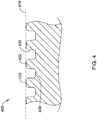
- FIG. 4 provides a schematic cross-section of a portion of a stop 400.
- stop 400 can represent any of the stops described in FIGS. 1-3 , such as stop 22, top stop 132, 232 or constraint layer stop 128, 228.
- Stop 400 may be considered as generally defining a surface 410, indicated by dashed lines.
- a number of recesses 430 may be formed in surface 410, thereby defining a number of projections 420.
- stop 400 may alternatively be considered as including a number of projections extending from a surface, with recesses defined between the projections.
- recesses 430 are etched into stop 400.
- the projections 420 may have front facing surfaces 422 that have rounded edges.
- each of the projections 420 have a front facing surface 422, and a combined surface area of all of the front facing surfaces 422 of the projections 420 may be between about 5 and 60 percent of the cross-sectional area defined by the overall cross-sectional area defined by the perimeter of the stop 400.
- the recesses 430 may be etched into stop 400 using an anisotropic etch, which may produce relatively sharp edges around the perimeter of the front facing surface 422 and down the etched side walls 432 of each of the projections 420.
- the anisotropic etch may be a Reactive Ion Etch, or any other suitable etch as desired. Thereafter, the sharp edges produced by the anisotropic etch may be rounded off by applying an isotropic etch. The length of time spend in the isotropic etch may dictate the relative degree to which the edges are rounded. In some instances, between 10-100% of the front facing surface 422 of the projections is rounded, with remainder (if any) being relatively flat and planer with respect to surface 410.
- the projections 420 may be formed by mechanically grinding, cutting, sandblasting, or otherwise mechanically manipulating a front facing surface of a stop, as desired.
- FIG. 5 is a top view of stop 400, illustrating an embodiment in which projections 420 are arranged in a regular pattern, in rows and columns.
- flow channels 440 may be defined between adjacent projections, and/or between adjacent rows and columns of projections 420.
- Flow channels 440 may be formed, for example, via etching.
- At least some of projections 420 may have an average height that is at least about 100 microns.
- FIGS. 4 and 5 illustrate a stop 400 having a planar profile.
- a suitable stop may have a curved or otherwise non-planar profile in order to reduce stiction, such as shown in FIG. 6 .
- FIG. 6 provides a schematic cross-section of a portion of a stop 600.
- stop 600 can represent any of the stops described in FIGS. 1-3 , such as stop 22, top stop 132, 232 or constraint layer stop 128, 228.
- Stop 600 may be considered as defining a surface 610, indicated by dashed lines. Unlike FIGS. 4 and 5 , which show a planar surface 410, surface 610 is curved. In some instances, a number of recesses 630 may be formed in surface 610, thereby defining a number of projections 620, 622, 624, 626, 628.
- surface 610 includes a first projection 620 that extends to a first height, a second projection 622 that extends to a second height, a third projection 624 that extends to a third height, a fourth projection 626 that extends to a fourth height and a fifth projection 628 that extends to a fifth height.
- the number of projections shown is illustrative only, and that stop 600 may have a larger number of projections. It can be seen that stop 600 is configured such that the projections closer to a periphery of stop 600 extend to a height that is less than projections that are closer to a center of stop 600, although this is not required.
- FIG. 6 is not to scale, as in some embodiments there may be a 5 to 15 micron difference in projection height between projections near the periphery of stop 600 relative to projections near the center of stop 600.
- projections 620, 622, 624, 626, 628 may be arranged in a regular pattern, such as projections 420 shown in FIG. 4 and 5 .
- surface 610 may be considered as defining a simple curve. In some embodiments, it is contemplated that surface 610 may not represent a simple curve, but rather may have a shape better described by an oscillating or sinusoidal curve. In some embodiments, surface 610 may be considered as being convex. In some embodiments, surface 610 may instead be concave.
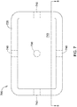
- FIG. 7 provides a top plan view of another illustrative stop 700.
- FIG. 8 provides a schematic cross-sectional view of the illustrative stop of FIG. 7 taken along line 8-8.
- stop 700 can represent any of the stops described in FIGS. 1-3 , such as stop 22, top stop 132, 232 or constraint layer stop 128, 228.
- Illustrative stop 700 includes a surface 710 and a raised perimeter 720 that extends above (in the illustrated orientation) surface 710. If an overpressure causes a sense diaphragm to contact stop 700, the sense diaphragm may only contact raised perimeter 720.
- stop 700 may also include one or more raised projections 730 that are located within surface 710.
- stop 700 may include any number of raised projections 730, arranged in any desired pattern on surface 710.
- raised perimeter 720 may include one or more cutouts 740. Cutouts 740, if present, may help the sense diaphragm move away from stop 700 by permitting fluid flow (e.g. air) between the sense diaphragm and surface 710 during movement of the sense diaphragm.
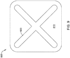
- FIG. 9 provides a top plan view of yet another illustrative stop 800.
- stop 800 can represent any of the stops described in FIGS. 1-3 , such as stop 22, top stop 132, 232 or constraint layer stop 128, 228.
- Illustrative stop 800 includes a surface 810 and a raised pattern 820.
- raised pattern 820 is in the shape of a large X, which may be in registration with an adjacent sense diaphragm (not shown). A variety of different shapes are contemplated.
- raised pattern 820 may be in the form of an asterisk.
- Raised pattern 820 may be in the form of a number sign, or hashtag.
- stop 800 may include a single raised pattern 820, as shown, or may include several relatively smaller raised patterns dispersed around surface 810.
Landscapes
- Physics & Mathematics (AREA)
- General Physics & Mathematics (AREA)
- Chemical & Material Sciences (AREA)
- Analytical Chemistry (AREA)
- Measuring Fluid Pressure (AREA)
Claims (14)
- Drucksensor (10) zum Abtasten eines Eingabedrucks, der Drucksensor Folgendes umfassend:eine Eingabe (24) zum Erhalten eines Eingabedrucks;einen Abtast-Chip (12) mit einer Abtastmembran (18), wobei die Abtastmembran dem Eingabedruck exponiert ist und konfiguriert ist, als Reaktion auf den Eingabedruck auszulenken;ein oder mehrere Abtastelemente (26), die wirksam mit der Abtastmembran verbunden sind, um eine Auslenkung der Abtastmembran abzutasten; undeinen ersten Membrananschlag (22), der einer ersten Seite der Abtastmembran benachbart angeordnet ist, um eine Auslenkung der Abtastmembran in Richtung auf den ersten Membrananschlag zu begrenzen, wobei der erste Membrananschlag eine erste Membrananschlagfläche (23) umfasst, die der ersten Seite der Abtastmembran gegenüber steht, wobei die erste Membrananschlagfläche konfiguriert ist, mit der Abtastmembran zusammenzuwirken, wenn die Abtastmembran aufgrund des Eingabedrucks um einen vordefinierten Betrag ausgelenkt wurde, wobei die erste Membrananschlagfläche mehrere definierte Vorsprünge umfasst, wobei die mehreren Vorsprünge auf der ersten Membrananschlagfläche Vertiefungen aufweisen, die dazwischen ausgebildet sind, wobei jeder der mehreren definierten Vorsprünge eine nach vorne stehende Oberfläche aufweist, die einen Teil der ersten Membrananschlagfläche definiert, und wobei die nach vorne stehende Oberfläche jeder der mehreren definierten Vorsprünge gerundete Kanten aufweist.
- Drucksensor nach Anspruch 1, wobei die mehreren definierten Vorsprünge in einem vordefinierten Muster angeordnet sind.
- Drucksensor nach den Ansprüchen 1 bis 2, wobei die mehreren definierten Vorsprünge einen oder mehrere Strömungskanäle zwischen den mehreren definierten Vorsprüngen umfassen.
- Drucksensor nach Anspruch 3, wobei der eine oder die mehreren Strömungskanäle geätzt sind und geätzte Seitenwände aufweisen.
- Drucksensor nach den Ansprüchen 1 bis 4, wobei mindestens einige der mehreren definierten Vorsprünge eine Höhe von mindestens 100 Mikron aufweisen.
- Drucksensor nach den Ansprüchen 1 bis 5, wobei sich jeder der mehreren definierten Vorsprünge auf eine Höhe erstreckt und wobei sich mindestens einige der mehreren definierten Vorsprünge, die näher an einem Außenrand der ersten Membrananschlagfläche angeordnet sind, auf eine Höhe erstrecken, die kleiner ist als die von mindestens einem der mehreren definierten Vorsprünge, die näher an einer Mitte der ersten Membrananschlagfläche angeordnet sind.
- Drucksensor nach den Ansprüchen 1 bis 6, wobei:ein erster Außenrand der Abtastmembran einen ersten Querschnittsflächenbereich definiert;ein zweiter Außenrand der ersten Membrananschlagfläche eine zweite Querschnittsfläche definiert, wobei die zweite Querschnittsfläche, die durch den zweiten Außenrand der ersten Membrananschlagfläche definiert ist, zwischen 10 und 95 Prozent der ersten Querschnittsfläche ist, die durch den ersten Außenrand der Abtastmembran definiert ist.
- Drucksensor nach Anspruch 7, wobei die zweite Querschnittsfläche, die durch den zweiten Außenrand der ersten Membrananschlagfläche definiert ist, zwischen 60 und 90 Prozent der ersten Querschnittsfläche ist, die durch den ersten Außenrand der Abtastmembran definiert ist.
- Drucksensor nach Anspruch 8, wobei jeder der mehreren definierten Vorsprünge eine nach vorne stehende Oberfläche aufweist und wobei die nach vorne stehenden Oberflächen aller der mehreren definierten Vorsprünge zusammen zwischen 5 und 60 Prozent der zweiten Querschnittsfläche sind, die durch den zweiten Außenrand der ersten Membrananschlagfläche definiert ist.
- Drucksensor nach den Ansprüchen 1 bis 9 wobei die Eingabe einen ersten Eingabeport zum Erhalten eines ersten Differenzdrucks und einen zweiten Eingabeport zum Erhalten eines zweiten Differenzdrucks umfasst, wobei die erste Seite der Abtastmembran dem ersten Differenzdruck exponiert ist und eine zweite Seite der Abtastmembran dem zweiten Differenzdruck exponiert ist.
- Drucksensor nach den Ansprüchen 1 bis 10, weiterhin Folgendes umfassend:
einen zweiten Membrananschlag, der benachbart der zweiten Seite der Abtastmembran angeordnet ist, um eine Auslenkung der Abtastmembran in Richtung auf den zweiten Membrananschlag zu begrenzen, wobei der zweite Membrananschlag eine Membrananschlagfläche umfasst, die der zweiten Seite der Abtastmembran gegenüber steht, wobei die Membrananschlagfläche mehrere definierte Vorsprünge umfasst. - Drucksensor nach Anspruch 1,
wobei der Abtast-Chip eine erste Hauptoberfläche und eine gegenüberliegende zweite Hauptoberfläche mit einer Vertiefung in der ersten Hauptoberfläche aufweist, um eine vertiefte erste Oberfläche auszubilden, wobei die Abtastmembran zwischen der vertieften ersten Oberfläche und der zweiten Hauptoberfläche des Abtast-Chips definiert ist, bei dem die erste Hauptoberfläche auf der ersten Seite der Abtastmembran ist;
wobei der Drucksensor weiterhin Folgendes umfasst:ein erstes Substrat, das hinsichtlich der ersten Hauptoberfläche des Abtast-Chips befestigt ist, wobei das erste Substrat den ersten Membrananschlag aufweist, der sich von dem ersten Substrat weg und in die Vertiefung in dem Abtast-Chip und benachbart der vertieften ersten Oberfläche der Abtastmembran erstreckt, um eine Auslenkung der Abtastmembran in Richtung auf den ersten Membrananschlag zu begrenzen; undein zweites Substrat hinsichtlich der zweiten Hauptoberfläche des Abtast-Chips befestigt ist. - Verfahren zum Abtasten eines Drucks, das Verfahren Folgendes umfassend:Erhalten eines Eingabedrucks an einem Abtast-Chip (12) mit einer Abtastmembran (18);Auslenken der Abtastmembran als Reaktion auf den Eingabedruck;Detektieren der Auslenkung der Abtastmembran unter Verwendung eines oder mehrerer Abtastelemente (26), die wirksam mit der Abtastmembran verbunden sind;Zusammenwirken der Abtastmembran mit einem ersten Membrananschlag (22) bei Auslenkung der Abtastmembran um einen vordefinierten Betrag;Begrenzen der Auslenkung der Abtastmembran als Reaktion auf das Zusammenwirken der Abtastmembran mit dem ersten Membrananschlag, wobei die erste Membrananschlagfläche mehrere definierte Vorsprünge umfasst, wobei die mehreren definierten Vorsprünge auf der ersten Membrananschlagfläche Vertiefungen aufweisen, die dazwischen ausgebildet sind, wobei jeder der mehreren definierten Vorsprünge eine nach vorne stehende Oberfläche aufweist, die einen Teil der ersten Membrananschlagfläche definiert, und wobei die nach vorne stehende Oberfläche jeder der mehreren definierten Vorsprünge gerundete Kanten aufweist.
- Verfahren nach Anspruch 13, wobei sich jeder der mehreren definierten Vorsprünge auf eine Höhe erstreckt und wobei sich mindestens einige der mehreren definierten Vorsprünge, die näher an einem Außenrand der ersten Membrananschlagfläche angeordnet sind, auf eine Höhe erstrecken, die kleiner ist als die von mindestens einem der mehreren definierten Vorsprünge, die näher an einer Mitte der ersten Membrananschlagfläche angeordnet sind.
Applications Claiming Priority (1)
| Application Number | Priority Date | Filing Date | Title |
|---|---|---|---|
| US14/225,059 US9410861B2 (en) | 2014-03-25 | 2014-03-25 | Pressure sensor with overpressure protection |
Publications (3)
| Publication Number | Publication Date |
|---|---|
| EP2924409A2 EP2924409A2 (de) | 2015-09-30 |
| EP2924409A3 EP2924409A3 (de) | 2016-01-27 |
| EP2924409B1 true EP2924409B1 (de) | 2019-05-15 |
Family
ID=52627139
Family Applications (1)
| Application Number | Title | Priority Date | Filing Date |
|---|---|---|---|
| EP15158319.2A Active EP2924409B1 (de) | 2014-03-25 | 2015-03-09 | Drucksensor mit Überdruckschutz |
Country Status (3)
| Country | Link |
|---|---|
| US (1) | US9410861B2 (de) |
| EP (1) | EP2924409B1 (de) |
| CN (3) | CN104949787B (de) |
Families Citing this family (10)
| Publication number | Priority date | Publication date | Assignee | Title |
|---|---|---|---|---|
| JP6424780B2 (ja) * | 2015-09-14 | 2018-11-21 | 株式会社デンソー | 力学量センサ |
| US9963340B2 (en) | 2015-12-03 | 2018-05-08 | Honeywell International Inc. | Pressure sensor die over pressure protection for high over pressure to operating span ratios |
| US10197462B2 (en) * | 2016-05-25 | 2019-02-05 | Honeywell International Inc. | Differential pressure sensor full overpressure protection device |
| US10571348B2 (en) * | 2016-08-30 | 2020-02-25 | Honeywell International Inc. | Overforce control through sense die design |
| US10203258B2 (en) * | 2016-09-26 | 2019-02-12 | Rosemount Inc. | Pressure sensor diaphragm with overpressure protection |
| CN110383028B (zh) * | 2017-03-10 | 2021-07-30 | 霍尼韦尔国际公司 | 输出误差减小的具有过压保护的压力传感器 |
| WO2020108718A1 (en) * | 2018-11-27 | 2020-06-04 | Grundfos Holding A/S | A cover for a pressure sensor |
| RU2706447C1 (ru) * | 2019-03-19 | 2019-11-19 | Российская Федерация, от имени которой выступает Государственная корпорация по атомной энергии "Росатом" (Госкорпорация "Росатом") | Микроэлектромеханический датчик давления |
| US11118992B2 (en) * | 2019-06-06 | 2021-09-14 | Measurement Specialties, Inc. | Pressure sensor assemblies with protective pressure feature |
| US11193842B2 (en) * | 2019-06-06 | 2021-12-07 | Te Connectivity Solutions Gmbh | Pressure sensor assemblies with protective pressure feature of a pressure mitigation element |
Family Cites Families (44)
| Publication number | Priority date | Publication date | Assignee | Title |
|---|---|---|---|---|
| DE4142001A1 (de) | 1991-12-19 | 1993-06-24 | Microparts Gmbh | Verfahren zum herstellen gestufter formeinsaetze, gestufte formeinsaetze und damit abgeformte mikrostrukturkoerper |
| GB1540716A (en) * | 1975-03-18 | 1979-02-14 | Bell & Howell Ltd | Pressure or force transducers |
| US4592238A (en) * | 1985-04-15 | 1986-06-03 | Gould Inc. | Laser-recrystallized diaphragm pressure sensor and method of making |
| US4852408A (en) | 1987-09-03 | 1989-08-01 | Scott Fetzer Company | Stop for integrated circuit diaphragm |
| US5062302A (en) | 1988-04-29 | 1991-11-05 | Schlumberger Industries, Inc. | Laminated semiconductor sensor with overpressure protection |
| US4905575A (en) | 1988-10-20 | 1990-03-06 | Rosemount Inc. | Solid state differential pressure sensor with overpressure stop and free edge construction |
| US5157973A (en) * | 1989-03-16 | 1992-10-27 | Process Automation Business, Inc. | Pressure sensor with integral overpressure protection |
| JPH03223638A (ja) * | 1989-11-16 | 1991-10-02 | Fuji Electric Co Ltd | 差圧検出装置 |
| US5220838A (en) | 1991-03-28 | 1993-06-22 | The Foxboro Company | Overpressure-protected, differential pressure sensor and method of making the same |
| US5333504A (en) * | 1992-09-01 | 1994-08-02 | Rosemount Inc. | High overpressure low range pressure sensor |
| US5381299A (en) * | 1994-01-28 | 1995-01-10 | United Technologies Corporation | Capacitive pressure sensor having a substrate with a curved mesa |
| US5880530A (en) | 1996-03-29 | 1999-03-09 | Intel Corporation | Multiregion solder interconnection structure |
| US6330829B1 (en) | 2000-03-16 | 2001-12-18 | Kulite Semiconductor Products Inc. | Oil-filled pressure transducer |
| JP2002340718A (ja) | 2001-05-16 | 2002-11-27 | Yokogawa Electric Corp | 圧力計 |
| US20030167851A1 (en) | 2002-01-30 | 2003-09-11 | Parker Gregory D. | Absolute micromachined silicon pressure sensor with backside hermetic cover and method of making the same |
| DE10235046A1 (de) * | 2002-07-31 | 2004-02-12 | Endress + Hauser Gmbh + Co. Kg | Kapazitiver Drucksensor |
| US6877380B2 (en) | 2002-10-01 | 2005-04-12 | Honeywell International Inc. | Diaphragm for bonded element sensor |
| US7082835B2 (en) | 2003-06-18 | 2006-08-01 | Honeywell International Inc. | Pressure sensor apparatus and method |
| JP3847281B2 (ja) * | 2003-08-20 | 2006-11-22 | 株式会社山武 | 圧力センサ装置 |
| FR2859281B1 (fr) * | 2003-09-02 | 2005-12-23 | Auxitrol Sa | Protection d'une membrane deformable contre de fortes deformations dans une structure micromecanique |
| US20050081638A1 (en) | 2003-09-05 | 2005-04-21 | Couch Philip R. | Sensing diaphragm for a differential pressure sensor with over-pressure protection and methods |
| US6923069B1 (en) | 2004-10-18 | 2005-08-02 | Honeywell International Inc. | Top side reference cavity for absolute pressure sensor |
| US7635077B2 (en) | 2005-09-27 | 2009-12-22 | Honeywell International Inc. | Method of flip chip mounting pressure sensor dies to substrates and pressure sensors formed thereby |
| US7260994B2 (en) | 2005-11-03 | 2007-08-28 | Honeywell International Inc. | Low cost high-pressure sensor |
| US7216547B1 (en) | 2006-01-06 | 2007-05-15 | Honeywell International Inc. | Pressure sensor with silicon frit bonded cap |
| US7503221B2 (en) * | 2006-11-08 | 2009-03-17 | Honeywell International Inc. | Dual span absolute pressure sense die |
| US7493822B2 (en) | 2007-07-05 | 2009-02-24 | Honeywell International Inc. | Small gauge pressure sensor using wafer bonding and electrochemical etch stopping |
| US7930944B2 (en) | 2008-05-14 | 2011-04-26 | Honeywell International Inc. | ASIC compensated pressure sensor with soldered sense die attach |
| JP5357469B2 (ja) * | 2008-05-23 | 2013-12-04 | アルプス電気株式会社 | 半導体圧力センサ |
| ITTO20080484A1 (it) * | 2008-06-19 | 2009-12-20 | Eltek Spa | Dispositivo sensore di pressione |
| US7647842B1 (en) | 2008-07-25 | 2010-01-19 | Honeywell International Inc. | Pressure-based fluid flow sensor |
| US8230745B2 (en) | 2008-11-19 | 2012-07-31 | Honeywell International Inc. | Wet/wet differential pressure sensor based on microelectronic packaging process |
| US8024978B2 (en) | 2009-01-21 | 2011-09-27 | Honeywell International Inc. | Media isolated pressure transducer having boss comprising single metal diaphragm |
| JP5092167B2 (ja) * | 2009-03-24 | 2012-12-05 | 三菱電機株式会社 | 半導体圧力センサおよびその製造方法 |
| EP2264399B1 (de) * | 2009-06-19 | 2012-05-30 | The Swatch Group Research and Development Ltd. | Drucksensor mit Membran und Tiefenmessgerät, das einen solchen Sensor umfasst |
| JP2013526083A (ja) | 2010-05-03 | 2013-06-20 | エス3シー インコーポレイテッド | ウエハ上のmemsダイ分離時のチッピングを最小にする方法 |
| CN102261979B (zh) * | 2010-05-26 | 2013-03-27 | 苏州敏芯微电子技术有限公司 | 用于真空测量的低量程压阻式压力传感器的制造方法 |
| US20120105385A1 (en) * | 2010-11-02 | 2012-05-03 | Qualcomm Mems Technologies, Inc. | Electromechanical systems apparatuses and methods for providing rough surfaces |
| US8671766B2 (en) * | 2011-05-19 | 2014-03-18 | Infineon Technologies Ag | Integrated pressure sensor seal |
| US20120313189A1 (en) * | 2011-06-08 | 2012-12-13 | Invensense, Inc. | Method of preventing stiction of mems devices |
| FR2982023B1 (fr) * | 2011-10-26 | 2015-03-06 | Auxitrol Sa | Structure micromecanique a membrane deformable et a protection contre de fortes deformations |
| US8516897B1 (en) | 2012-02-21 | 2013-08-27 | Honeywell International Inc. | Pressure sensor |
| JP5897940B2 (ja) * | 2012-03-14 | 2016-04-06 | アズビル株式会社 | 圧力センサチップ |
| JP5997570B2 (ja) * | 2012-10-15 | 2016-09-28 | アズビル株式会社 | 圧力センサチップ |
-
2014
- 2014-03-25 US US14/225,059 patent/US9410861B2/en active Active
-
2015
- 2015-03-09 EP EP15158319.2A patent/EP2924409B1/de active Active
- 2015-03-24 CN CN201510129398.3A patent/CN104949787B/zh not_active Expired - Fee Related
- 2015-03-24 CN CN202010300014.0A patent/CN111397792B/zh active Active
- 2015-03-24 CN CN202010300625.5A patent/CN111397793B/zh active Active
Non-Patent Citations (1)
| Title |
|---|
| None * |
Also Published As
| Publication number | Publication date |
|---|---|
| CN104949787A (zh) | 2015-09-30 |
| CN111397793A (zh) | 2020-07-10 |
| CN111397792A (zh) | 2020-07-10 |
| CN111397792B (zh) | 2022-03-15 |
| EP2924409A3 (de) | 2016-01-27 |
| EP2924409A2 (de) | 2015-09-30 |
| US9410861B2 (en) | 2016-08-09 |
| CN104949787B (zh) | 2020-05-05 |
| US20150276526A1 (en) | 2015-10-01 |
| CN111397793B (zh) | 2022-04-12 |
Similar Documents
| Publication | Publication Date | Title |
|---|---|---|
| EP2924409B1 (de) | Drucksensor mit Überdruckschutz | |
| US7992443B2 (en) | Sensor element for capacitive differential-pressure sensing | |
| RU2464467C1 (ru) | Передатчик давления и манометр | |
| EP2474820B1 (de) | Drucksensor mit kostengünstiger Verpackung | |
| CN102782324B (zh) | 制造至少一变形膜微泵的方法及变形膜微泵 | |
| JP6022587B2 (ja) | 変形可能な膜と強い変形に対する保護とを有する微小機械構造 | |
| CN107894294B (zh) | 带有扩展浅多边形腔的带腔绝缘体上硅mems压力传感装置 | |
| CN108458829B (zh) | 静电电容型压力传感器 | |
| CN103308245A (zh) | 差压传感器 | |
| EP2993455A1 (de) | Sensor, dehnungssensor und drucksensor | |
| CN107209077A (zh) | 具有改进的凹部或者空腔结构的微型机械装置 | |
| CN104204755B (zh) | 微机械的压力传感器 | |
| US9395259B2 (en) | Piezoresistive transducer with low thermal noise | |
| CN106164638A (zh) | 压力传感器芯片 | |
| US9010200B2 (en) | Device for measuring forces and method of making the same | |
| US20170176277A1 (en) | Pressure sensor chip | |
| EP3196617A1 (de) | Mems-drucksensor mit modifiziertem hohlraum zur verbesserung des berstdrucks | |
| CN104181331A (zh) | 一种压阻式加速度传感器及其制造方法 | |
| JP7113487B2 (ja) | 脈波センサ | |
| CN107421663A (zh) | 用于模收缩和高灵敏度的具有锚定件的压力传感器装置 | |
| Arjunan et al. | Modeling and analysis of a multi bossed beam membrane sensor for environmental applications | |
| JP7736425B2 (ja) | 圧力センサ素子および圧力センサ | |
| JP7736508B2 (ja) | 圧力センサ素子および圧力センサ | |
| KR100625358B1 (ko) | 압력 센서 및 그 제조 방법 | |
| JP2012233708A (ja) | 圧力測定器の製造方法 |
Legal Events
| Date | Code | Title | Description |
|---|---|---|---|
| PUAI | Public reference made under article 153(3) epc to a published international application that has entered the european phase |
Free format text: ORIGINAL CODE: 0009012 |
|
| 17P | Request for examination filed |
Effective date: 20150309 |
|
| AK | Designated contracting states |
Kind code of ref document: A2 Designated state(s): AL AT BE BG CH CY CZ DE DK EE ES FI FR GB GR HR HU IE IS IT LI LT LU LV MC MK MT NL NO PL PT RO RS SE SI SK SM TR |
|
| AX | Request for extension of the european patent |
Extension state: BA ME |
|
| RAP1 | Party data changed (applicant data changed or rights of an application transferred) |
Owner name: HONEYWELL INTERNATIONAL INC. |
|
| PUAL | Search report despatched |
Free format text: ORIGINAL CODE: 0009013 |
|
| AK | Designated contracting states |
Kind code of ref document: A3 Designated state(s): AL AT BE BG CH CY CZ DE DK EE ES FI FR GB GR HR HU IE IS IT LI LT LU LV MC MK MT NL NO PL PT RO RS SE SI SK SM TR |
|
| AX | Request for extension of the european patent |
Extension state: BA ME |
|
| RIC1 | Information provided on ipc code assigned before grant |
Ipc: G01L 13/02 20060101ALI20151222BHEP Ipc: G01L 19/06 20060101ALI20151222BHEP Ipc: G01L 9/00 20060101AFI20151222BHEP |
|
| GRAP | Despatch of communication of intention to grant a patent |
Free format text: ORIGINAL CODE: EPIDOSNIGR1 |
|
| STAA | Information on the status of an ep patent application or granted ep patent |
Free format text: STATUS: GRANT OF PATENT IS INTENDED |
|
| INTG | Intention to grant announced |
Effective date: 20181130 |
|
| GRAS | Grant fee paid |
Free format text: ORIGINAL CODE: EPIDOSNIGR3 |
|
| GRAJ | Information related to disapproval of communication of intention to grant by the applicant or resumption of examination proceedings by the epo deleted |
Free format text: ORIGINAL CODE: EPIDOSDIGR1 |
|
| GRAL | Information related to payment of fee for publishing/printing deleted |
Free format text: ORIGINAL CODE: EPIDOSDIGR3 |
|
| STAA | Information on the status of an ep patent application or granted ep patent |
Free format text: STATUS: REQUEST FOR EXAMINATION WAS MADE |
|
| GRAP | Despatch of communication of intention to grant a patent |
Free format text: ORIGINAL CODE: EPIDOSNIGR1 |
|
| STAA | Information on the status of an ep patent application or granted ep patent |
Free format text: STATUS: GRANT OF PATENT IS INTENDED |
|
| GRAA | (expected) grant |
Free format text: ORIGINAL CODE: 0009210 |
|
| STAA | Information on the status of an ep patent application or granted ep patent |
Free format text: STATUS: THE PATENT HAS BEEN GRANTED |
|
| INTC | Intention to grant announced (deleted) | ||
| INTG | Intention to grant announced |
Effective date: 20190401 |
|
| AK | Designated contracting states |
Kind code of ref document: B1 Designated state(s): AL AT BE BG CH CY CZ DE DK EE ES FI FR GB GR HR HU IE IS IT LI LT LU LV MC MK MT NL NO PL PT RO RS SE SI SK SM TR |
|
| REG | Reference to a national code |
Ref country code: CH Ref legal event code: EP |
|
| REG | Reference to a national code |
Ref country code: DE Ref legal event code: R096 Ref document number: 602015030211 Country of ref document: DE |
|
| REG | Reference to a national code |
Ref country code: IE Ref legal event code: FG4D |
|
| REG | Reference to a national code |
Ref country code: NL Ref legal event code: MP Effective date: 20190515 |
|
| REG | Reference to a national code |
Ref country code: LT Ref legal event code: MG4D |
|
| PG25 | Lapsed in a contracting state [announced via postgrant information from national office to epo] |
Ref country code: HR Free format text: LAPSE BECAUSE OF FAILURE TO SUBMIT A TRANSLATION OF THE DESCRIPTION OR TO PAY THE FEE WITHIN THE PRESCRIBED TIME-LIMIT Effective date: 20190515 Ref country code: NL Free format text: LAPSE BECAUSE OF FAILURE TO SUBMIT A TRANSLATION OF THE DESCRIPTION OR TO PAY THE FEE WITHIN THE PRESCRIBED TIME-LIMIT Effective date: 20190515 Ref country code: FI Free format text: LAPSE BECAUSE OF FAILURE TO SUBMIT A TRANSLATION OF THE DESCRIPTION OR TO PAY THE FEE WITHIN THE PRESCRIBED TIME-LIMIT Effective date: 20190515 Ref country code: LT Free format text: LAPSE BECAUSE OF FAILURE TO SUBMIT A TRANSLATION OF THE DESCRIPTION OR TO PAY THE FEE WITHIN THE PRESCRIBED TIME-LIMIT Effective date: 20190515 Ref country code: PT Free format text: LAPSE BECAUSE OF FAILURE TO SUBMIT A TRANSLATION OF THE DESCRIPTION OR TO PAY THE FEE WITHIN THE PRESCRIBED TIME-LIMIT Effective date: 20190915 Ref country code: SE Free format text: LAPSE BECAUSE OF FAILURE TO SUBMIT A TRANSLATION OF THE DESCRIPTION OR TO PAY THE FEE WITHIN THE PRESCRIBED TIME-LIMIT Effective date: 20190515 Ref country code: NO Free format text: LAPSE BECAUSE OF FAILURE TO SUBMIT A TRANSLATION OF THE DESCRIPTION OR TO PAY THE FEE WITHIN THE PRESCRIBED TIME-LIMIT Effective date: 20190815 Ref country code: AL Free format text: LAPSE BECAUSE OF FAILURE TO SUBMIT A TRANSLATION OF THE DESCRIPTION OR TO PAY THE FEE WITHIN THE PRESCRIBED TIME-LIMIT Effective date: 20190515 Ref country code: ES Free format text: LAPSE BECAUSE OF FAILURE TO SUBMIT A TRANSLATION OF THE DESCRIPTION OR TO PAY THE FEE WITHIN THE PRESCRIBED TIME-LIMIT Effective date: 20190515 |
|
| PG25 | Lapsed in a contracting state [announced via postgrant information from national office to epo] |
Ref country code: GR Free format text: LAPSE BECAUSE OF FAILURE TO SUBMIT A TRANSLATION OF THE DESCRIPTION OR TO PAY THE FEE WITHIN THE PRESCRIBED TIME-LIMIT Effective date: 20190816 Ref country code: BG Free format text: LAPSE BECAUSE OF FAILURE TO SUBMIT A TRANSLATION OF THE DESCRIPTION OR TO PAY THE FEE WITHIN THE PRESCRIBED TIME-LIMIT Effective date: 20190815 Ref country code: RS Free format text: LAPSE BECAUSE OF FAILURE TO SUBMIT A TRANSLATION OF THE DESCRIPTION OR TO PAY THE FEE WITHIN THE PRESCRIBED TIME-LIMIT Effective date: 20190515 Ref country code: LV Free format text: LAPSE BECAUSE OF FAILURE TO SUBMIT A TRANSLATION OF THE DESCRIPTION OR TO PAY THE FEE WITHIN THE PRESCRIBED TIME-LIMIT Effective date: 20190515 |
|
| REG | Reference to a national code |
Ref country code: AT Ref legal event code: MK05 Ref document number: 1134001 Country of ref document: AT Kind code of ref document: T Effective date: 20190515 |
|
| PG25 | Lapsed in a contracting state [announced via postgrant information from national office to epo] |
Ref country code: EE Free format text: LAPSE BECAUSE OF FAILURE TO SUBMIT A TRANSLATION OF THE DESCRIPTION OR TO PAY THE FEE WITHIN THE PRESCRIBED TIME-LIMIT Effective date: 20190515 Ref country code: AT Free format text: LAPSE BECAUSE OF FAILURE TO SUBMIT A TRANSLATION OF THE DESCRIPTION OR TO PAY THE FEE WITHIN THE PRESCRIBED TIME-LIMIT Effective date: 20190515 Ref country code: DK Free format text: LAPSE BECAUSE OF FAILURE TO SUBMIT A TRANSLATION OF THE DESCRIPTION OR TO PAY THE FEE WITHIN THE PRESCRIBED TIME-LIMIT Effective date: 20190515 Ref country code: SK Free format text: LAPSE BECAUSE OF FAILURE TO SUBMIT A TRANSLATION OF THE DESCRIPTION OR TO PAY THE FEE WITHIN THE PRESCRIBED TIME-LIMIT Effective date: 20190515 Ref country code: RO Free format text: LAPSE BECAUSE OF FAILURE TO SUBMIT A TRANSLATION OF THE DESCRIPTION OR TO PAY THE FEE WITHIN THE PRESCRIBED TIME-LIMIT Effective date: 20190515 Ref country code: CZ Free format text: LAPSE BECAUSE OF FAILURE TO SUBMIT A TRANSLATION OF THE DESCRIPTION OR TO PAY THE FEE WITHIN THE PRESCRIBED TIME-LIMIT Effective date: 20190515 |
|
| REG | Reference to a national code |
Ref country code: DE Ref legal event code: R097 Ref document number: 602015030211 Country of ref document: DE |
|
| PG25 | Lapsed in a contracting state [announced via postgrant information from national office to epo] |
Ref country code: SM Free format text: LAPSE BECAUSE OF FAILURE TO SUBMIT A TRANSLATION OF THE DESCRIPTION OR TO PAY THE FEE WITHIN THE PRESCRIBED TIME-LIMIT Effective date: 20190515 Ref country code: IT Free format text: LAPSE BECAUSE OF FAILURE TO SUBMIT A TRANSLATION OF THE DESCRIPTION OR TO PAY THE FEE WITHIN THE PRESCRIBED TIME-LIMIT Effective date: 20190515 |
|
| PLBE | No opposition filed within time limit |
Free format text: ORIGINAL CODE: 0009261 |
|
| STAA | Information on the status of an ep patent application or granted ep patent |
Free format text: STATUS: NO OPPOSITION FILED WITHIN TIME LIMIT |
|
| PG25 | Lapsed in a contracting state [announced via postgrant information from national office to epo] |
Ref country code: TR Free format text: LAPSE BECAUSE OF FAILURE TO SUBMIT A TRANSLATION OF THE DESCRIPTION OR TO PAY THE FEE WITHIN THE PRESCRIBED TIME-LIMIT Effective date: 20190515 |
|
| 26N | No opposition filed |
Effective date: 20200218 |
|
| PG25 | Lapsed in a contracting state [announced via postgrant information from national office to epo] |
Ref country code: PL Free format text: LAPSE BECAUSE OF FAILURE TO SUBMIT A TRANSLATION OF THE DESCRIPTION OR TO PAY THE FEE WITHIN THE PRESCRIBED TIME-LIMIT Effective date: 20190515 |
|
| PG25 | Lapsed in a contracting state [announced via postgrant information from national office to epo] |
Ref country code: SI Free format text: LAPSE BECAUSE OF FAILURE TO SUBMIT A TRANSLATION OF THE DESCRIPTION OR TO PAY THE FEE WITHIN THE PRESCRIBED TIME-LIMIT Effective date: 20190515 |
|
| PG25 | Lapsed in a contracting state [announced via postgrant information from national office to epo] |
Ref country code: MC Free format text: LAPSE BECAUSE OF FAILURE TO SUBMIT A TRANSLATION OF THE DESCRIPTION OR TO PAY THE FEE WITHIN THE PRESCRIBED TIME-LIMIT Effective date: 20190515 |
|
| REG | Reference to a national code |
Ref country code: CH Ref legal event code: PL |
|
| REG | Reference to a national code |
Ref country code: BE Ref legal event code: MM Effective date: 20200331 |
|
| PG25 | Lapsed in a contracting state [announced via postgrant information from national office to epo] |
Ref country code: LU Free format text: LAPSE BECAUSE OF NON-PAYMENT OF DUE FEES Effective date: 20200309 |
|
| PG25 | Lapsed in a contracting state [announced via postgrant information from national office to epo] |
Ref country code: LI Free format text: LAPSE BECAUSE OF NON-PAYMENT OF DUE FEES Effective date: 20200331 Ref country code: IE Free format text: LAPSE BECAUSE OF NON-PAYMENT OF DUE FEES Effective date: 20200309 Ref country code: CH Free format text: LAPSE BECAUSE OF NON-PAYMENT OF DUE FEES Effective date: 20200331 |
|
| PG25 | Lapsed in a contracting state [announced via postgrant information from national office to epo] |
Ref country code: BE Free format text: LAPSE BECAUSE OF NON-PAYMENT OF DUE FEES Effective date: 20200331 |
|
| PG25 | Lapsed in a contracting state [announced via postgrant information from national office to epo] |
Ref country code: MT Free format text: LAPSE BECAUSE OF FAILURE TO SUBMIT A TRANSLATION OF THE DESCRIPTION OR TO PAY THE FEE WITHIN THE PRESCRIBED TIME-LIMIT Effective date: 20190515 Ref country code: CY Free format text: LAPSE BECAUSE OF FAILURE TO SUBMIT A TRANSLATION OF THE DESCRIPTION OR TO PAY THE FEE WITHIN THE PRESCRIBED TIME-LIMIT Effective date: 20190515 |
|
| PG25 | Lapsed in a contracting state [announced via postgrant information from national office to epo] |
Ref country code: MK Free format text: LAPSE BECAUSE OF FAILURE TO SUBMIT A TRANSLATION OF THE DESCRIPTION OR TO PAY THE FEE WITHIN THE PRESCRIBED TIME-LIMIT Effective date: 20190515 Ref country code: IS Free format text: LAPSE BECAUSE OF FAILURE TO SUBMIT A TRANSLATION OF THE DESCRIPTION OR TO PAY THE FEE WITHIN THE PRESCRIBED TIME-LIMIT Effective date: 20190915 |
|
| PGFP | Annual fee paid to national office [announced via postgrant information from national office to epo] |
Ref country code: GB Payment date: 20260319 Year of fee payment: 12 |
|
| PGFP | Annual fee paid to national office [announced via postgrant information from national office to epo] |
Ref country code: DE Payment date: 20260320 Year of fee payment: 12 |
|
| PGFP | Annual fee paid to national office [announced via postgrant information from national office to epo] |
Ref country code: FR Payment date: 20260323 Year of fee payment: 12 |