EP2924171B1 - Rammhammer - Google Patents
Rammhammer Download PDFInfo
- Publication number
- EP2924171B1 EP2924171B1 EP14162394.2A EP14162394A EP2924171B1 EP 2924171 B1 EP2924171 B1 EP 2924171B1 EP 14162394 A EP14162394 A EP 14162394A EP 2924171 B1 EP2924171 B1 EP 2924171B1
- Authority
- EP
- European Patent Office
- Prior art keywords
- piston
- pile driving
- driving hammer
- cylinder
- hammer according
- Prior art date
- Legal status (The legal status is an assumption and is not a legal conclusion. Google has not performed a legal analysis and makes no representation as to the accuracy of the status listed.)
- Not-in-force
Links
- 239000002775 capsule Substances 0.000 claims description 11
- 239000000446 fuel Substances 0.000 claims description 11
- 239000000463 material Substances 0.000 claims description 10
- 238000002485 combustion reaction Methods 0.000 claims description 7
- VYPSYNLAJGMNEJ-UHFFFAOYSA-N Silicium dioxide Chemical compound O=[Si]=O VYPSYNLAJGMNEJ-UHFFFAOYSA-N 0.000 claims description 5
- 239000007788 liquid Substances 0.000 claims description 3
- 229910000831 Steel Inorganic materials 0.000 claims description 2
- 229910052782 aluminium Inorganic materials 0.000 claims description 2
- XAGFODPZIPBFFR-UHFFFAOYSA-N aluminium Chemical compound [Al] XAGFODPZIPBFFR-UHFFFAOYSA-N 0.000 claims description 2
- 239000002184 metal Substances 0.000 claims description 2
- 229910052751 metal Inorganic materials 0.000 claims description 2
- 239000002245 particle Substances 0.000 claims description 2
- 239000010959 steel Substances 0.000 claims description 2
- XLYOFNOQVPJJNP-UHFFFAOYSA-N water Substances O XLYOFNOQVPJJNP-UHFFFAOYSA-N 0.000 claims description 2
- 239000011796 hollow space material Substances 0.000 claims 3
- 239000003082 abrasive agent Substances 0.000 claims 2
- 239000004411 aluminium Substances 0.000 claims 1
- 239000011133 lead Substances 0.000 claims 1
- 239000004576 sand Substances 0.000 claims 1
- 239000000377 silicon dioxide Substances 0.000 claims 1
- 238000013016 damping Methods 0.000 description 9
- 238000010521 absorption reaction Methods 0.000 description 6
- 239000000945 filler Substances 0.000 description 4
- 239000000314 lubricant Substances 0.000 description 4
- 238000011161 development Methods 0.000 description 3
- 230000018109 developmental process Effects 0.000 description 3
- 238000002347 injection Methods 0.000 description 3
- 239000007924 injection Substances 0.000 description 3
- 239000006004 Quartz sand Substances 0.000 description 2
- 238000005422 blasting Methods 0.000 description 2
- 239000013590 bulk material Substances 0.000 description 2
- 239000003795 chemical substances by application Substances 0.000 description 2
- 239000002828 fuel tank Substances 0.000 description 2
- 238000007789 sealing Methods 0.000 description 2
- 238000000889 atomisation Methods 0.000 description 1
- 239000000567 combustion gas Substances 0.000 description 1
- 239000002283 diesel fuel Substances 0.000 description 1
- 229920001971 elastomer Polymers 0.000 description 1
- 239000000806 elastomer Substances 0.000 description 1
- 239000002360 explosive Substances 0.000 description 1
- 239000002657 fibrous material Substances 0.000 description 1
- 230000005484 gravity Effects 0.000 description 1
- 238000000034 method Methods 0.000 description 1
- 239000000203 mixture Substances 0.000 description 1
- 239000004745 nonwoven fabric Substances 0.000 description 1
- 230000002093 peripheral effect Effects 0.000 description 1
- 230000001960 triggered effect Effects 0.000 description 1
- 238000003466 welding Methods 0.000 description 1
Images

Classifications
-
- E—FIXED CONSTRUCTIONS
- E02—HYDRAULIC ENGINEERING; FOUNDATIONS; SOIL SHIFTING
- E02D—FOUNDATIONS; EXCAVATIONS; EMBANKMENTS; UNDERGROUND OR UNDERWATER STRUCTURES
- E02D7/00—Methods or apparatus for placing sheet pile bulkheads, piles, mouldpipes, or other moulds
- E02D7/02—Placing by driving
- E02D7/06—Power-driven drivers
- E02D7/12—Drivers with explosion chambers
- E02D7/125—Diesel drivers
Definitions
- the invention relates to a pile hammer, comprising a cylinder, a piston displaceably guided in the cylinder and a striking piece displaceably guided in the cylinder according to the preamble of patent claim 1.
- the invention aims to remedy this situation.
- the invention is based on the object to provide a piling hammer, which allows a ramming of concrete piles without the need for an additional damping package. According to the invention, this object is solved by the features of the characterizing part of patent claim 1.
- a pile hammer which allows a ramming of concrete piles without the requirement of a damping package between hammer and concrete pile.
- the cavity of the piston is closed by a cover detachably connected to the piston.
- a cover detachably connected to the piston.
- the filler is preferably formed from bulk material or from a liquid.
- quartz sand or metal blasting agents in particular steel or aluminum blasting agents, are used as bulk material.
- Suitable liquids are, for example, oil or water.
- the filler is formed from particles having a substantially round geometry.
- a projection for engaging a release device is arranged on the piston at its opposite end of the combustion chamber.
- a capsule hood which can be placed on a concrete pile and has an opening for the passage of the hammer.
- the capsule hood can also be formed fastened to the cylinder of the pile hammer.
- a sound-absorbing sheathing of the impact surface is effected, whereby a reduction of the noise emissions is effected. Since the impact of the hammer on the pile is a main source of noise, this causes a significant reduction in the noise level during the piling process.
- the passage opening surrounding at least one sound absorption element is arranged on the capsule hood.
- more or less homogeneous or fibrous materials whose thickness is defined by the lower frequency at which almost complete absorption of the impinging sound waves can still be achieved are suitable as sound absorption elements.
- a corresponding Absorption can also be achieved by arranging a suitable flow resistance, for example in the form of a nonwoven fabric, that is clamped, for example, on a perforated plate with a perforation in the form of holes or slits that is sufficiently large and as evenly distributed as possible.
- the diesel ram selected as an exemplary embodiment comprises a cylinder 1 which is open on both sides and which can regularly have a length of 3 to 8 meters and a diameter of 0.2 to 1.5 meters.
- a piston 2 is slidably disposed in the cylinder 1 a.
- a coaxial to this impact piece 3 engages slidably in the open lower end of the cylinder 1 a.
- an annular bearing unit 9 is fixed, in which a middle shaft portion 31 of the hammering piece 3 is guided tightly and displaceably, which has a relation to the inner diameter of the cylinder 1 reduced outer diameter.
- the diesel ram is slidably mounted on arranged on the cylinder 1 guide jaws 13 along a Switzerland cartiklers.
- the outwardly directed lower convex boundary surface 33 cooperates in operation with the upper end of a concrete pile 8 to be driven.
- a piston portion 34 is formed with a plurality of circumferential, axially spaced sealing rings which run on the inner circumferential surface 11 of the cylinder 1.
- a combustion chamber 12 is limited together with the underside of the piston 2 and the inner circumferential surface 11 of the cylinder 1.
- the combustion chamber 12 of the cylinder 1 facing end face of the hammer 3 is ground flat with a flat fuel bowl 30.
- a damping ring 91 is arranged between the impact plate 32 of the hammer 3 and the bearing unit 9 of the cylinder 1.
- a further damping ring 92 is arranged adjacent to the position unit 9 between the upper side of the layer unit 9 and the underside of the piston section 34 of the striking piece 3.
- hammer 3 runs in the interior of the cylinder 1 with a circumferential, axially spaced-apart sealing rings 93 provided lower working end 23 of the piston 2.
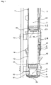
- the lower free, ground flat surface 21 of the piston 2 is offset by a radially circumferential step.
- a mass portion 22 is formed, which extends into the upper portion of the cylinder 1 inside and having a cavity 24 inside.
- the cavity 24 is closed at its end face 21 opposite the end of the piston 2 with a cover 25.
- the lid 25 is fastened in the exemplary embodiment via screws 251 on the piston 2.
- the cover 25 is provided with a threaded bore 252.
- the threaded bore 252 serves to engage a screw anchor, which is not shown, for handling the cover 25.
- a projection 26 is integrally formed on the outside of the piston 2 on the outside. The projection 26 serves to receive the hook 71 of a notching device 7.
- the cavity 24 of the piston 2 is filled in the embodiment with quartz sand.
- an injection device 4 On the peripheral wall of the cylinder 1, an injection device 4 is arranged, which comprises a fuel pump 41 which is connected via a line 43 to the injection nozzle 42. The inlet of the fuel pump 41 is fed via a fuel tank 5 with diesel oil.
- the fuel pump 41 which is connected to the fuel tank 5 via the line 43, has a prestressed pump lever 44 projecting into the interior of the cylinder 1, via which it is driven when the falling piston 2 passes.
- the injection nozzle 42 is designed and aligned such that the discharged fuel is injected in a substantially continuous beam approximately centrally on the end face of the hammer 3.
- a lubricant pump 51 is arranged on the cylinder 1, which is connected to distributed in the circumferential direction of the cylinder 1 lubricant nozzles. Through the lubricant nozzles, the lubricant between the piston 2 and the inner circumferential surface 11 of the cylinder 1 is given.
- FIG. 3 the use of the hammer is shown with a capsule hood 6.
- the capsule hood 6 is formed substantially hollow cylindrical and has at its end facing the hammering hammer on an annularly designed sound absorption element 61, which limits the passage opening 62.
- a pile receptacle 63 is arranged in the capsule hood 6, which is provided on its the pile 8 side facing with an elastomer layer 64.
- the capsule hood 6 is used to reduce the noise emissions during impact of the hammer 3.
- the pile hammer described above operates as follows: in the initial state, the piston 2 is raised via a release device 7 in an upper position. For this purpose, the hook 71 of the notching device 7 engages in the projection 26 of the piston 2 and the piston is subsequently over pulled the hook 71 upwards, which hook is connected thereto with a cable drive 72. After disengaging the hook 71, the piston 2 falls under the action of gravity down, closes the working nozzle 16 and actuates with its end face 21 the pump lever 44 of the injector 4, which is sprayed through the injector 42 fuel to the fuel bowl 30 of the hammer 3. Impact atomization forms an ignitable mixture of fuel droplets and air.
Landscapes
- Engineering & Computer Science (AREA)
- Life Sciences & Earth Sciences (AREA)
- General Life Sciences & Earth Sciences (AREA)
- Mining & Mineral Resources (AREA)
- Paleontology (AREA)
- Civil Engineering (AREA)
- General Engineering & Computer Science (AREA)
- Structural Engineering (AREA)
- Placing Or Removing Of Piles Or Sheet Piles, Or Accessories Thereof (AREA)
Description
- Die Erfindung betrifft einen Rammhammer, umfassend einen Zylinder, einen in dem Zylinder verschiebbar geführten Kolben und einen in dem Zylinder verschiebbar geführten Schlagstück nach dem Oberbegriff des Patentanspruchs 1.
- Beim Rammen vom Betonpfählen besteht regelmäßig die Problematik, dass die geringen maximal zulässigen Druck- bzw. Zugspannungen im Pfahl besondere Maßnahmen erfordern, um eine Beschädigung der Betonpfähle zu vermeiden. Hierzu wird zwischen dem Werkstück der Ramme und dem Pfahl ein Dämpfungspaket angeordnet, um Beschädigungen des Betonpfahls entgegen zu wirken.
- Nachteilig an der vorbekannten Anordnung ist, dass vor dem Rammen eines jeden Betonpfahls jeweils ein Dämpfungspaket angebracht werden muss, wodurch der Aufwand erhöht ist.
- Hier will die Erfindung Abhilfe schaffen. Der Erfindung liegt die Aufgabe zu Grunde, einen Rammhammer bereitzustellen, der ein Rammen von Betonpfählen ohne das Erfordernis eines zusätzlichen Dämpfungspaketes ermöglicht. Gemäß der Erfindung wird diese Aufgabe durch die Merkmale des kennzeichnenden Teil des Patentanspruchs 1 gelöst.
- Mit der Erfindung ist ein Rammhammer bereit gestellt, der ein Rammen von Betonpfählen ohne das Erfordernis eines Dämpfungspaketes zwischen Schlagstück und Betonpfahl ermöglicht. Durch die Ausbildung des Kolbens mit einem Hohlraum, der zumindest teilweise mit einem beweglichen Füllstoff gefüllt ist, wird eine Dämpfung des Schlages erzielt, wodurch einer Beschädigung des Betonpfahls ohne das Erfordernis eines zusätzlichen Dämpfungspaketes entgegengewirkt ist.
- In Weiterbildung der Erfindung ist der Hohlraum des Kolbens über einen lösbar mit dem Kolben verbundenen Deckel verschlossen. Hierdurch ist im Gegensatz zur - ebenfalls möglichen - nicht lösbaren Befestigung, bspw. mittels Schweißen - das Einbringen unterschiedlicher Füllstoffe ermöglicht, wodurch je nach Material des zu rammenden Pfahls eine unterschiedliche Dämpfung einstellbar ist. Bevorzugt ist der Füllstoff aus Schüttgut oder aus einer Flüssigkeit gebildet. Als Schüttgut kommen hier insbesondere Quartzsand oder auch Metallstrahlmittel, insbesondere Stahl- oder Aluminiumstrahlmittel zum Einsatz. Geeignete Flüssigkeit sind beispielsweise Öl oder Wasser.
- In Weiterbildung der Erfindung ist der Füllstoff aus Partikeln mit im Wesentlichen runder Geometrie gebildet. Hierdurch ist eine geringe Setzzeit des Materials erzielt, wodurch ein optimaier Dämpfungsveriauf bewirkt ist.
- In weiterer Ausgestaltung der Erfindung ist an dem Kolben an seinem dem Brennraum gegenüberliegenden Ende ein Vorsprung zum Eingriff einer Ausklinkvorrichtung angeordnet. Hierdurch kann die dem Stand der Technik erforderliche Aufziehnut des Zylinders entfallen, da der Aufziehvorgang vollständig außerhalb des Zylinders erfolgt.
- In weiterer Ausgestaltung der Erfindung ist eine Kapselhaube vorgesehen, welche an einem Betonpfahl aufgesetzt werden kann und eine Öffnung für den Durchtritt des Schlagstücks aufweist. Alternativ kann die Kapselhaube auch an dem Zylinder des Rammhammers befestigbar ausgebildet sein. Hierdurch ist eine schallabsorbierende Ummantelung der Aufschlagfläche bewirkt, wodurch eine Reduktion der Schallemissionen bewirkt ist. Da der Aufschlag des Schlagstücks auf dem Pfahl eine Hauptschallquelle darstellt, ist hierdurch eine signifikante Reduzierung des Lärmpegels beim Rammvorgang bewirkt. Vorteilhaft ist an der Kapselhaube die Durchtrittsöffnung umgebend wenigstens ein Schallabsorptionselement angeordnet. Als Schallabsorptionselemente eignen sich insbesondere mehr oder weniger homogene oder faserige Materialien, deren Dicke durch die untere Frequenz definiert ist, bei der noch nahezu vollständige Absorption der auftreffenden Schallwellen erreichbar ist. Eine dementsprechende Absorption kann auch durch Anordnung eines geeigneten Strömungswiderstandes, beispielsweise in Form eines Faservlieses erzielt werden, dass beispielsweise auf ein Lochblech mit ausreichend großer und möglichst gleichmäßig verteilter Perforation in Form von Löcher oder Schlitzen aufgespannt ist.
- Andere Weiterbildungen und Ausgestaltungen der Erfindung sind in den übrigen Unteransprüchen angegeben. Ein Ausführungsbeispiel der Erfindung ist in den Zeichnungen dargestellt und wird nachfolgend im Einzelnen beschrieben. Es zeigen:
- Figur 1
- die schematische Darstellung eines Rammhammers in Form einer Dieselramme;
- Figur 2
- die Darstellung des Kolbens des Rammhammers aus
Figur 1 ; - Figur 3
- die schematische Darstellung der Anordnung einer Kapselhaube zwischen Rammhammer und Betonpfahl und
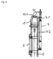
- Figur 4
- die schematische Darstellung des oberen Abschnitts des Rammhammers aus
Figur 1 mit angeordneter Ausklinkvorrichtung. - Die als Ausführungsbeispiel gewählte Dieselramme umfasst einen beidseitig offenen Zylinder 1, der regelmäßig eine Länge von 3 bis 8 Metern und einem Durchmesser von 0,2 bis 1,5 Meter aufweisen kann. In dem Zylinder 1 ist ein Kolben 2 verschiebbar angeordnet. Ein hierzu koaxiales Schlagstück 3 greift verschiebbar in das offene untere Ende des Zylinders 1 ein. An dem unteren Ende des Zylinders 1 ist eine ringförmige Lagereinheit 9 befestigt, in der ein mittlerer Schaftabschnitt 31 des Schlagstücks 3 dicht und verschiebbar geführt ist, der einen gegenüber dem Innendurchmesser des Zylinders 1 verminderten Außendurchmesser aufweist. Die Dieselramme ist über an dem Zylinder 1 angeordnete Führungsbacken 13 entlang eines Mäklers verschiebbar gelagert.
- An dem unteren Ende des Schaftabschnitts 31 ist eine unterhalb des Zylinders 1 liegende Schlagplatte 32 angeformt, deren nach außen gerichtete untere konvexe Begrenzungsfläche 33 im Betrieb mit dem oberen Ende eines einzutreibenden Betonpfahles 8 zusammenwirkt.
- An dem oberen Ende des Schaftabschnitts 31 des Schlagstücks 3 ist ein Kolbenabschnitt 34 mit mehreren umlaufenden, axial beabstandeten Dichtringen angeformt, die auf der Innenmantelfläche 11 des Zylinders 1 laufen. Durch die Oberseite des Kolbenabschnitts 34 des Schlagstücks 3 ist zusammen mit der Unterseite des Kolbens 2 sowie der Innenmantelfläche 11 des Zylinders 1 ein Brennraum 12 begrenzt. Die den Brennraum 12 des Zylinders 1 zugewandte Stirnfläche des Schlagstücks 3 ist plan mit einer flachen Brennstoffmulde 30 geschliffen.
- Zwischen der Schlagplatte 32 des Schlagstücks 3 und der Lagereinheit 9 des Zylinders 1 ist ein Dämpfungsring 91 angeordnet. Ein weiterer Dämpfungsring 92 ist benachbart zur Lageeinheit 9 zwischen der Oberseite der Lageeinheit 9 und der Unterseite des Kolbenabschnitts 34 des Schlagstücks 3 angeordnet.
- Oberhalb des Schlagstücks 3 läuft im Inneren des Zylinders 1 ein mit umlaufenden, axial zueinander beabstandeten Dichtringen 93 versehenes unteres Arbeitsende 23 des Kolbens 2. Die untere freie, plangeschliffene Stirnfläche 21 des Kolbens 2 ist durch eine radial umlaufende Stufe abgesetzt.
- An dem unteren Arbeitsende 23 des Kolbens 2 ist ein Massenabschnitt 22 angeformt, der sich in den oberen Abschnitt des Zylinders 1 hinein erstreckt und der innen einen Hohlraum 24 aufweist. Der Hohlraum 24 ist an seinem der Stirnfläche 21 gegenüberliegenden Ende des Kolbens 2 mit einem Deckel 25 verschlossen. Der Deckel 25 ist im Ausführungsbeispiel über Schrauben 251 an dem Kolben 2 befestigt. Mittig ist der Deckel 25 mit einer Gewindebohrung 252 versehen. Die Gewindebohrung 252 dient dem Eingriff eines -nicht dargestellten- Schraubankers zur Handhabung des Deckels 25. Im Bereich des Deckels 25 ist an dem Kolben 2 endseitig außen umlaufend ein Vorsprung 26 angeformt. Der Vorsprung 26 dient der Aufnahme des Hakens 71 einer Ausklinkvorrichtung 7. Der Hohlraum 24 des Kolbens 2 ist im Ausführungsbeispiel mit Quartzsand befüllt.
- An der Umfangswand des Zylinders 1 ist eine Einspritzvorrichtung 4 angeordnet, die eine Kraftstoffpumpe 41 umfasst, die über eine Leitung 43 mit der Einspritzdüse 42 verbunden ist. Der Einlass der Kraftstoffpumpe 41 wird über einen Kraftstofftank 5 mit Dieselöl gespeist.
- Die über die Leitung 43 mit dem Kraftstofftank 5 verbundene Kraftstoffpumpe 41 weist einen ins Innere des Zylinders 1 ragenden, vorgespannten Pumpenhebel 44 auf, über den sie bei Passieren des fallenden Kolbens 2 angetrieben wird. Die Einspritzdüse 42 ist derart ausgebildet und ausgerichtet, dass der abgegebene Kraftstoff in einen im Wesentlichen zusammenhängenden Strahl etwa mittig auf die Stirnfläche des Schlagstücks 3 gespritzt wird.
- Weiterhin ist an dem Zylinder 1 eine Schmierstoffpumpe 51 angeordnet, die mit in Umfangsrichtung des Zylinders 1 verteilten Schmierstoffdüsen verbunden ist. Durch die Schmierstoffdüsen wird der Schmierstoff zwischen den Kolben 2 und die Innenmantelfläche 11 des Zylinders 1 gegeben.
- In
Figur 3 ist der Einsatz des Rammhammers mit einer Kapselhaube 6 dargestellt. Die Kapselhaube 6 ist im Wesentlichen hohlzylindrisch ausgebildet und weist an ihrem dem Rammhammer zugewandten Ende ein ringförmig ausgebildetes Schallabsorptionselement 61 auf, welches die Durchtrittsöffnung 62 begrenzt. Unterhalb des Schallabsorptionselementes 61 ist in der Kapselhaube 6 eine Pfahlaufnahme 63 angeordnet, die an ihrer dem Pfahl 8 zugewandten Seite mit einer Elastomerschicht 64 versehen ist. Die Kapselhaube 6 dient der Reduktion der Schallemissionen beim Aufschlag des Schlagstücks 3. - Der zuvor beschriebene Rammhammer arbeitet folgendermaßen: im Ausgangszustand ist der Kolben 2 über eine Ausklinkvorrichtung 7 in eine obere Stellung angehoben. Hierzu greift der Haken 71 der Ausklinkvorrichtung 7 in den Vorsprung 26 des Kolbens 2 ein und der Kolben wird nachfolgend über den Haken 71 nach oben gezogen, welcher Haken hierzu mit einem Seiltrieb 72 verbunden ist. Nach Ausklinken des Hakens 71 fällt der Kolben 2 unter Einwirkung der Schwerkraft nach unten, verschließt die Arbeitsstutzen 16 und betätigt mit seiner Stirnfläche 21 den Pumpenhebel 44 der Einspritzvorrichtung 4, wodurch über die Einspritzdüse 42 Kraftstoff auf die Brennstoffmulde 30 des Schlagstücks 3 gespritzt wird. Hier bildet sich durch Schlagzerstäubung ein zündfähiges Gemisch aus Kraftstofftröpfchen und Luft.
- Mit dem Aufschlagen des Kolbens 2 auf das Schlagstück 3 wird durch das Schlagstück 3 und über dieses auf den Betonpfahl 8 eine nach unten gerichtete Kraft ausgeübt, welche den Betonpfahl 8 weiter in das Erdreich treibt. Aufgrund des in dem Hohlraum 24 des Kolbens 2 eingebrachten Quartzsandes wird der Impuls des Kolbens gedämpft, wodurch eine Beschädigung des Betonpfahls beim Aufschlag gegengewirkt wird. Der bei dem Aufschlag des Kolbens 2 auf das Schlagstück 3 und über dieses auf den Betonpfahl 8 emittierte Schall wird dabei durch die Kapselhaube 6 reduziert.
- Bei der anschließend durch die explosionsartige Verbrennung des Kraftstoffs ausgelösten Aufwärtsbewegung des Kolbens 2 gibt dieser die Arbeitsstutzen 16 frei, wodurch sich die Verbrennungsgase entspannen und über die Arbeitsstutzen 16 abströmen. Der Kolben 2 wird nun unter Ansaugen von frischer Luft durch die Arbeitsstutzen 16 weiter nach oben geschleudert, bis er seine obere Endstellung erreicht hat und sich der beschriebene Arbeitszyklus wiederholt.
Claims (9)
- Rammhammer, umfassend einen Zylinder (1), einen in dem Zylinder (1) verschiebbar geführten Kolben (2), ein in dem Zylinder (1) verschiebbar geführtes Schlagstück (3), welches in Betriebsstellung des Rammhammers unterhalb des Kolbens (2) angeordnet ist, einem Brennraum (12), der axial von einer im Inneren des Zylinders (1) liegenden Stirnfläche (30) des Schlagstücks (3) und einer Stirnfläche (21) des Kolbens (2) begrenzt ist, sowie wenigstens einer Kraftstoffzuführeinrichtung, durch die bei jedem Arbeitszyklus eine vorgegebene Menge Kraftstoff in den Brennraum (12) einbringbar ist, dadurch gekennzeichnet, dass der Kolben (2) einen Hohlraum (24) aufweist, der zumindest teilweise mit einem zweiten, vom Kolbenwerkstoff verschiedenen Füllstoff gefüllt ist, wobei der Füllstoff innerhalb des Hohlraums beweglich angeordnet ist.
- Rammhammer nach Anspruch 1, dadurch gekennzeichnet, dass der Hohlraum (24) des Kolbens (2) über einen lösbar mit dem Kolben (2) verbundenen Deckel (25) verschlossen ist.
- Rammhammer nach Anspruch 1 oder 2, dadurch gekennzeichnet, dass der Füllstoff aus Schüttgut und/oder einer Flüssigkeit gebildet ist.
- Rammhammer nach Anspruch 3, dadurch gekennzeichnet, dass der Füllstoff Quarzsand und/oder Metallstrahlmittel, insbesondere Stahl-, Blei- oder Aluminiumstrahlmittel enthält.
- Rammhammer nach Anspruch 4, dadurch gekennzeichnet, dass der Füllstoff aus Partikeln mit im Wesentlichen runder Geometrie gebildet ist.
- Rammhammer nach Anspruch 5, dadurch gekennzeichnet, dass der Füllstoff aus Wasser und/oder Öl gebildet ist.
- Rammhammer nach einem der vorgenannten Ansprüche, dadurch gekennzeichnet, dass an dem Kolben (2) an seinem dem Brennraum (12) gegenüber liegenden Ende ein Vorsprung (26) zum Eingriff einer Ausklinkvorrichtung (7) angeordnet ist.
- Rammhammer nach einem der vorgenannten Ansprüche, dadurch gekennzeichnet, dass eine Kapselhaube (6) vorgesehen ist, welche auf einem Betonpfahl (8) aufsetzbar ist und eine Öffnung (62) für den Durchtritt des Schlagstücks (3) aufweist.
- Rammhammer nach Anspruch 8, dadurch gekennzeichnet, dass an der Kapselhaube (6) die Durchtrittsöffnung (62) umgebend wenigstens ein Schallabsorbtionselement (61) angeordnet ist.
Priority Applications (3)
| Application Number | Priority Date | Filing Date | Title |
|---|---|---|---|
| EP14162394.2A EP2924171B1 (de) | 2014-03-28 | 2014-03-28 | Rammhammer |
| US14/663,549 US20150275458A1 (en) | 2014-03-28 | 2015-03-20 | Pile hammer |
| CN201510138543.4A CN104947667A (zh) | 2014-03-28 | 2015-03-27 | 撞锤 |
Applications Claiming Priority (1)
| Application Number | Priority Date | Filing Date | Title |
|---|---|---|---|
| EP14162394.2A EP2924171B1 (de) | 2014-03-28 | 2014-03-28 | Rammhammer |
Publications (2)
| Publication Number | Publication Date |
|---|---|
| EP2924171A1 EP2924171A1 (de) | 2015-09-30 |
| EP2924171B1 true EP2924171B1 (de) | 2016-07-13 |
Family
ID=50389326
Family Applications (1)
| Application Number | Title | Priority Date | Filing Date |
|---|---|---|---|
| EP14162394.2A Not-in-force EP2924171B1 (de) | 2014-03-28 | 2014-03-28 | Rammhammer |
Country Status (3)
| Country | Link |
|---|---|
| US (1) | US20150275458A1 (de) |
| EP (1) | EP2924171B1 (de) |
| CN (1) | CN104947667A (de) |
Families Citing this family (2)
| Publication number | Priority date | Publication date | Assignee | Title |
|---|---|---|---|---|
| CN105274990B (zh) * | 2015-11-17 | 2017-08-22 | 上海工程机械厂有限公司 | 一种柴油锤的循环水冷却系统 |
| FR3116174B1 (fr) * | 2020-11-16 | 2022-12-02 | Georges Mandrafina | Dispositif attele, pour l'implantation au defile, notamment des piquets, avec compensation de declivite |
Family Cites Families (28)
| Publication number | Priority date | Publication date | Assignee | Title |
|---|---|---|---|---|
| US2723532A (en) * | 1955-11-15 | Pile driving cap block | ||
| US886193A (en) * | 1907-11-12 | 1908-04-28 | Frank L Aymond | Compressed-air-cushion block. |
| US2633832A (en) * | 1949-07-22 | 1953-04-07 | Syntron Co | Diesel hammer |
| US3130762A (en) * | 1961-06-21 | 1964-04-28 | Henry K Kerr | Hammer with detachable striking head faces |
| US3788402A (en) * | 1970-12-29 | 1974-01-29 | Bolt Associates Inc | Automatically self-regulating variable-stroke, variable-rate and quiet-operating pile driver apparatus |
| US3721095A (en) * | 1971-08-23 | 1973-03-20 | Bolt Associates Inc | Controllable force method and system of driving piles |
| SE370099B (de) * | 1971-10-18 | 1974-09-30 | B Ludvigson | |
| US3927722A (en) * | 1974-02-08 | 1975-12-23 | Leonard L Frederick | Pile driving moving cylinder hammer with valved, fixed piston |
| NL148971B (nl) * | 1974-05-20 | 1976-03-15 | Kooten Bv V | Leidgestel voor een heiinrichting. |
| NL7513421A (nl) * | 1975-11-17 | 1977-05-20 | Kooten Bv V | Cilinderstuk voor een heiblok. |
| US4020804A (en) * | 1975-12-08 | 1977-05-03 | Fmc Corporation | Diesel pile hammer with vent for starting |
| DE2557704C3 (de) * | 1975-12-20 | 1982-05-13 | Koehring Gmbh, 2086 Ellerau | Schlagübertragungsvorrichtung für Rammgeräte |
| US4187917A (en) * | 1977-11-30 | 1980-02-12 | Hydroacoustics, Inc. | Pile driver |
| US4473123A (en) * | 1982-08-05 | 1984-09-25 | Raymond International Builders, Inc. | Diesel hammer capable of delivering uplift blows and method of using same |
| US4523647A (en) * | 1983-03-16 | 1985-06-18 | International Construction Equipment, Inc. | Power hammer |
| US4580641A (en) * | 1983-04-28 | 1986-04-08 | Raymond International Builders, Inc. | Method and apparatus for starting diesel type hammers |
| DE3545880A1 (de) * | 1985-12-23 | 1987-06-25 | Lindenmeyer Gmbh & Co Geb | Dieselramme |
| US5117924A (en) * | 1991-01-15 | 1992-06-02 | Berminghammer Corporation Limited | Energy transfer unit for a pile driver |
| DE19529538A1 (de) * | 1995-08-11 | 1997-02-13 | Delmag Maschinenfabrik | Ramme |
| US5727639A (en) * | 1996-03-11 | 1998-03-17 | Lee Matherne | Pile driving hammer improvement |
| US6557647B2 (en) * | 2000-05-30 | 2003-05-06 | American Piledriving Equipment, Inc. | Impact hammer systems and methods |
| DE10115681A1 (de) * | 2001-03-29 | 2002-10-10 | Delmag Gmbh & Co Kg | Dieselbär |
| US6595087B2 (en) * | 2001-11-21 | 2003-07-22 | Snap-On Technologies, Inc. | Encapsulated dead blow hammer with improved skeleton |
| US6942430B1 (en) * | 2004-03-10 | 2005-09-13 | Paul W. Suver | Rotary driver for pipe piling |
| DE102004062043A1 (de) * | 2004-12-23 | 2006-07-13 | Delmag Gmbh & Co. Kg | Dieselhammer |
| US20100303552A1 (en) * | 2009-05-27 | 2010-12-02 | American Piledriving Equipment, Inc. | Helmet adapter for pile drivers |
| US8763719B2 (en) * | 2010-01-06 | 2014-07-01 | American Piledriving Equipment, Inc. | Pile driving systems and methods employing preloaded drop hammer |
| CN102031779B (zh) * | 2010-11-16 | 2012-07-25 | 上海申启星海洋工程有限公司 | 双导内冷柴油打桩锤 |
-
2014
- 2014-03-28 EP EP14162394.2A patent/EP2924171B1/de not_active Not-in-force
-
2015
- 2015-03-20 US US14/663,549 patent/US20150275458A1/en not_active Abandoned
- 2015-03-27 CN CN201510138543.4A patent/CN104947667A/zh active Pending
Also Published As
| Publication number | Publication date |
|---|---|
| US20150275458A1 (en) | 2015-10-01 |
| CN104947667A (zh) | 2015-09-30 |
| EP2924171A1 (de) | 2015-09-30 |
Similar Documents
| Publication | Publication Date | Title |
|---|---|---|
| DE2163933C3 (de) | Vorrichtung zum Rammen eines Pfahles | |
| EP2871286B1 (de) | Rammhammer | |
| DE2250848A1 (de) | Verfahren und vorrichtung zum erzeugen einer druckwelle in einem langgestreckten koerper | |
| DE2641453C3 (de) | Verfahren und Vorrichtung zum Brechen von Gestein | |
| EP2924171B1 (de) | Rammhammer | |
| EP2767636B1 (de) | Dieselramme | |
| DE1292586B (de) | Verfahren und Vorrichtung zum Herstellen eines Betonmantelrohres | |
| EP1828488B1 (de) | Dieselhammer | |
| DE2410360A1 (de) | Rammvorrichtung | |
| DE3390073C2 (de) | Dieselramme | |
| EP3243573B1 (de) | Schwingungserzeuger | |
| DE3028857A1 (de) | Verfahren und vorrichtung zur erzeugung eines kraeftigen abwaertsstosses | |
| EP2871288B1 (de) | Dieselramme | |
| EP3339564B1 (de) | Vorrichtung und verfahren zur entnahme einer probe | |
| DE2159963A1 (de) | Kugel-Behälter und Einrichtung zur Steuerung von Kavitation in Flüssigkeiten | |
| EP2871287B1 (de) | Dieselramme | |
| EP2924170A1 (de) | Rammhammer | |
| EP2924172B1 (de) | Rammhammer | |
| DE102011075817A1 (de) | Bolzenführung für eine Nagelvorrichtung und eine Vorrichtung, welche die Bolzenführung aufweist | |
| EP2995721B1 (de) | Rammhammer | |
| DE1951292A1 (de) | Vorrichtung zum Einrammen und/oder Ausziehen von Pfaehlen | |
| DE102013101550A1 (de) | Dieselramme | |
| DE2120517C3 (de) | Felszerkleinerungs-Kanone | |
| DE1728550A1 (de) | Pneumatischer schlaghammer | |
| DE2913284C2 (de) |
Legal Events
| Date | Code | Title | Description |
|---|---|---|---|
| PUAI | Public reference made under article 153(3) epc to a published international application that has entered the european phase |
Free format text: ORIGINAL CODE: 0009012 |
|
| 17P | Request for examination filed |
Effective date: 20141126 |
|
| AK | Designated contracting states |
Kind code of ref document: A1 Designated state(s): AL AT BE BG CH CY CZ DE DK EE ES FI FR GB GR HR HU IE IS IT LI LT LU LV MC MK MT NL NO PL PT RO RS SE SI SK SM TR |
|
| AX | Request for extension of the european patent |
Extension state: BA ME |
|
| 17Q | First examination report despatched |
Effective date: 20160115 |
|
| GRAP | Despatch of communication of intention to grant a patent |
Free format text: ORIGINAL CODE: EPIDOSNIGR1 |
|
| INTG | Intention to grant announced |
Effective date: 20160316 |
|
| GRAR | Information related to intention to grant a patent recorded |
Free format text: ORIGINAL CODE: EPIDOSNIGR71 |
|
| GRAS | Grant fee paid |
Free format text: ORIGINAL CODE: EPIDOSNIGR3 |
|
| INTG | Intention to grant announced |
Effective date: 20160504 |
|
| GRAA | (expected) grant |
Free format text: ORIGINAL CODE: 0009210 |
|
| AK | Designated contracting states |
Kind code of ref document: B1 Designated state(s): AL AT BE BG CH CY CZ DE DK EE ES FI FR GB GR HR HU IE IS IT LI LT LU LV MC MK MT NL NO PL PT RO RS SE SI SK SM TR |
|
| REG | Reference to a national code |
Ref country code: GB Ref legal event code: FG4D Free format text: NOT ENGLISH |
|
| REG | Reference to a national code |
Ref country code: AT Ref legal event code: REF Ref document number: 812452 Country of ref document: AT Kind code of ref document: T Effective date: 20160715 Ref country code: CH Ref legal event code: EP |
|
| REG | Reference to a national code |
Ref country code: IE Ref legal event code: FG4D Free format text: LANGUAGE OF EP DOCUMENT: GERMAN |
|
| GRAT | Correction requested after decision to grant or after decision to maintain patent in amended form |
Free format text: ORIGINAL CODE: EPIDOSNCDEC |
|
| REG | Reference to a national code |
Ref country code: DE Ref legal event code: R096 Ref document number: 502014001082 Country of ref document: DE |
|
| REG | Reference to a national code |
Ref country code: NL Ref legal event code: FP |
|
| REG | Reference to a national code |
Ref country code: LT Ref legal event code: MG4D |
|
| PG25 | Lapsed in a contracting state [announced via postgrant information from national office to epo] |
Ref country code: NO Free format text: LAPSE BECAUSE OF FAILURE TO SUBMIT A TRANSLATION OF THE DESCRIPTION OR TO PAY THE FEE WITHIN THE PRESCRIBED TIME-LIMIT Effective date: 20161013 Ref country code: IT Free format text: LAPSE BECAUSE OF FAILURE TO SUBMIT A TRANSLATION OF THE DESCRIPTION OR TO PAY THE FEE WITHIN THE PRESCRIBED TIME-LIMIT Effective date: 20160713 Ref country code: IS Free format text: LAPSE BECAUSE OF FAILURE TO SUBMIT A TRANSLATION OF THE DESCRIPTION OR TO PAY THE FEE WITHIN THE PRESCRIBED TIME-LIMIT Effective date: 20161113 Ref country code: FI Free format text: LAPSE BECAUSE OF FAILURE TO SUBMIT A TRANSLATION OF THE DESCRIPTION OR TO PAY THE FEE WITHIN THE PRESCRIBED TIME-LIMIT Effective date: 20160713 Ref country code: RS Free format text: LAPSE BECAUSE OF FAILURE TO SUBMIT A TRANSLATION OF THE DESCRIPTION OR TO PAY THE FEE WITHIN THE PRESCRIBED TIME-LIMIT Effective date: 20160713 Ref country code: HR Free format text: LAPSE BECAUSE OF FAILURE TO SUBMIT A TRANSLATION OF THE DESCRIPTION OR TO PAY THE FEE WITHIN THE PRESCRIBED TIME-LIMIT Effective date: 20160713 Ref country code: LT Free format text: LAPSE BECAUSE OF FAILURE TO SUBMIT A TRANSLATION OF THE DESCRIPTION OR TO PAY THE FEE WITHIN THE PRESCRIBED TIME-LIMIT Effective date: 20160713 |
|
| PG25 | Lapsed in a contracting state [announced via postgrant information from national office to epo] |
Ref country code: LV Free format text: LAPSE BECAUSE OF FAILURE TO SUBMIT A TRANSLATION OF THE DESCRIPTION OR TO PAY THE FEE WITHIN THE PRESCRIBED TIME-LIMIT Effective date: 20160713 Ref country code: GR Free format text: LAPSE BECAUSE OF FAILURE TO SUBMIT A TRANSLATION OF THE DESCRIPTION OR TO PAY THE FEE WITHIN THE PRESCRIBED TIME-LIMIT Effective date: 20161014 Ref country code: ES Free format text: LAPSE BECAUSE OF FAILURE TO SUBMIT A TRANSLATION OF THE DESCRIPTION OR TO PAY THE FEE WITHIN THE PRESCRIBED TIME-LIMIT Effective date: 20160713 Ref country code: PT Free format text: LAPSE BECAUSE OF FAILURE TO SUBMIT A TRANSLATION OF THE DESCRIPTION OR TO PAY THE FEE WITHIN THE PRESCRIBED TIME-LIMIT Effective date: 20161114 Ref country code: PL Free format text: LAPSE BECAUSE OF FAILURE TO SUBMIT A TRANSLATION OF THE DESCRIPTION OR TO PAY THE FEE WITHIN THE PRESCRIBED TIME-LIMIT Effective date: 20160713 Ref country code: SE Free format text: LAPSE BECAUSE OF FAILURE TO SUBMIT A TRANSLATION OF THE DESCRIPTION OR TO PAY THE FEE WITHIN THE PRESCRIBED TIME-LIMIT Effective date: 20160713 |
|
| REG | Reference to a national code |
Ref country code: DE Ref legal event code: R097 Ref document number: 502014001082 Country of ref document: DE |
|
| PG25 | Lapsed in a contracting state [announced via postgrant information from national office to epo] |
Ref country code: EE Free format text: LAPSE BECAUSE OF FAILURE TO SUBMIT A TRANSLATION OF THE DESCRIPTION OR TO PAY THE FEE WITHIN THE PRESCRIBED TIME-LIMIT Effective date: 20160713 Ref country code: RO Free format text: LAPSE BECAUSE OF FAILURE TO SUBMIT A TRANSLATION OF THE DESCRIPTION OR TO PAY THE FEE WITHIN THE PRESCRIBED TIME-LIMIT Effective date: 20160713 |
|
| PLBE | No opposition filed within time limit |
Free format text: ORIGINAL CODE: 0009261 |
|
| STAA | Information on the status of an ep patent application or granted ep patent |
Free format text: STATUS: NO OPPOSITION FILED WITHIN TIME LIMIT |
|
| PG25 | Lapsed in a contracting state [announced via postgrant information from national office to epo] |
Ref country code: CZ Free format text: LAPSE BECAUSE OF FAILURE TO SUBMIT A TRANSLATION OF THE DESCRIPTION OR TO PAY THE FEE WITHIN THE PRESCRIBED TIME-LIMIT Effective date: 20160713 Ref country code: SM Free format text: LAPSE BECAUSE OF FAILURE TO SUBMIT A TRANSLATION OF THE DESCRIPTION OR TO PAY THE FEE WITHIN THE PRESCRIBED TIME-LIMIT Effective date: 20160713 Ref country code: DK Free format text: LAPSE BECAUSE OF FAILURE TO SUBMIT A TRANSLATION OF THE DESCRIPTION OR TO PAY THE FEE WITHIN THE PRESCRIBED TIME-LIMIT Effective date: 20160713 Ref country code: SK Free format text: LAPSE BECAUSE OF FAILURE TO SUBMIT A TRANSLATION OF THE DESCRIPTION OR TO PAY THE FEE WITHIN THE PRESCRIBED TIME-LIMIT Effective date: 20160713 Ref country code: BG Free format text: LAPSE BECAUSE OF FAILURE TO SUBMIT A TRANSLATION OF THE DESCRIPTION OR TO PAY THE FEE WITHIN THE PRESCRIBED TIME-LIMIT Effective date: 20161013 |
|
| 26N | No opposition filed |
Effective date: 20170418 |
|
| PG25 | Lapsed in a contracting state [announced via postgrant information from national office to epo] |
Ref country code: SI Free format text: LAPSE BECAUSE OF FAILURE TO SUBMIT A TRANSLATION OF THE DESCRIPTION OR TO PAY THE FEE WITHIN THE PRESCRIBED TIME-LIMIT Effective date: 20160713 |
|
| REG | Reference to a national code |
Ref country code: CH Ref legal event code: PL |
|
| PG25 | Lapsed in a contracting state [announced via postgrant information from national office to epo] |
Ref country code: MC Free format text: LAPSE BECAUSE OF FAILURE TO SUBMIT A TRANSLATION OF THE DESCRIPTION OR TO PAY THE FEE WITHIN THE PRESCRIBED TIME-LIMIT Effective date: 20160713 |
|
| REG | Reference to a national code |
Ref country code: IE Ref legal event code: MM4A |
|
| REG | Reference to a national code |
Ref country code: FR Ref legal event code: ST Effective date: 20171130 |
|
| PG25 | Lapsed in a contracting state [announced via postgrant information from national office to epo] |
Ref country code: FR Free format text: LAPSE BECAUSE OF NON-PAYMENT OF DUE FEES Effective date: 20170331 Ref country code: LU Free format text: LAPSE BECAUSE OF NON-PAYMENT OF DUE FEES Effective date: 20170328 |
|
| PG25 | Lapsed in a contracting state [announced via postgrant information from national office to epo] |
Ref country code: CH Free format text: LAPSE BECAUSE OF NON-PAYMENT OF DUE FEES Effective date: 20170331 Ref country code: LI Free format text: LAPSE BECAUSE OF NON-PAYMENT OF DUE FEES Effective date: 20170331 Ref country code: IE Free format text: LAPSE BECAUSE OF NON-PAYMENT OF DUE FEES Effective date: 20170328 |
|
| REG | Reference to a national code |
Ref country code: BE Ref legal event code: MM Effective date: 20170331 |
|
| PG25 | Lapsed in a contracting state [announced via postgrant information from national office to epo] |
Ref country code: BE Free format text: LAPSE BECAUSE OF NON-PAYMENT OF DUE FEES Effective date: 20170331 |
|
| PG25 | Lapsed in a contracting state [announced via postgrant information from national office to epo] |
Ref country code: MT Free format text: LAPSE BECAUSE OF FAILURE TO SUBMIT A TRANSLATION OF THE DESCRIPTION OR TO PAY THE FEE WITHIN THE PRESCRIBED TIME-LIMIT Effective date: 20160713 |
|
| PG25 | Lapsed in a contracting state [announced via postgrant information from national office to epo] |
Ref country code: AL Free format text: LAPSE BECAUSE OF FAILURE TO SUBMIT A TRANSLATION OF THE DESCRIPTION OR TO PAY THE FEE WITHIN THE PRESCRIBED TIME-LIMIT Effective date: 20160713 |
|
| GBPC | Gb: european patent ceased through non-payment of renewal fee |
Effective date: 20180328 |
|
| PG25 | Lapsed in a contracting state [announced via postgrant information from national office to epo] |
Ref country code: GB Free format text: LAPSE BECAUSE OF NON-PAYMENT OF DUE FEES Effective date: 20180328 |
|
| PGFP | Annual fee paid to national office [announced via postgrant information from national office to epo] |
Ref country code: NL Payment date: 20190321 Year of fee payment: 6 |
|
| PG25 | Lapsed in a contracting state [announced via postgrant information from national office to epo] |
Ref country code: HU Free format text: LAPSE BECAUSE OF FAILURE TO SUBMIT A TRANSLATION OF THE DESCRIPTION OR TO PAY THE FEE WITHIN THE PRESCRIBED TIME-LIMIT; INVALID AB INITIO Effective date: 20140328 |
|
| PGFP | Annual fee paid to national office [announced via postgrant information from national office to epo] |
Ref country code: DE Payment date: 20190329 Year of fee payment: 6 |
|
| PG25 | Lapsed in a contracting state [announced via postgrant information from national office to epo] |
Ref country code: CY Free format text: LAPSE BECAUSE OF FAILURE TO SUBMIT A TRANSLATION OF THE DESCRIPTION OR TO PAY THE FEE WITHIN THE PRESCRIBED TIME-LIMIT Effective date: 20160713 |
|
| PG25 | Lapsed in a contracting state [announced via postgrant information from national office to epo] |
Ref country code: MK Free format text: LAPSE BECAUSE OF FAILURE TO SUBMIT A TRANSLATION OF THE DESCRIPTION OR TO PAY THE FEE WITHIN THE PRESCRIBED TIME-LIMIT Effective date: 20160713 |
|
| PG25 | Lapsed in a contracting state [announced via postgrant information from national office to epo] |
Ref country code: TR Free format text: LAPSE BECAUSE OF FAILURE TO SUBMIT A TRANSLATION OF THE DESCRIPTION OR TO PAY THE FEE WITHIN THE PRESCRIBED TIME-LIMIT Effective date: 20160713 |
|
| REG | Reference to a national code |
Ref country code: AT Ref legal event code: MM01 Ref document number: 812452 Country of ref document: AT Kind code of ref document: T Effective date: 20190328 |
|
| REG | Reference to a national code |
Ref country code: DE Ref legal event code: R119 Ref document number: 502014001082 Country of ref document: DE |
|
| REG | Reference to a national code |
Ref country code: NL Ref legal event code: MM Effective date: 20200401 |
|
| PG25 | Lapsed in a contracting state [announced via postgrant information from national office to epo] |
Ref country code: AT Free format text: LAPSE BECAUSE OF NON-PAYMENT OF DUE FEES Effective date: 20190328 |
|
| PG25 | Lapsed in a contracting state [announced via postgrant information from national office to epo] |
Ref country code: NL Free format text: LAPSE BECAUSE OF NON-PAYMENT OF DUE FEES Effective date: 20200401 |
|
| PG25 | Lapsed in a contracting state [announced via postgrant information from national office to epo] |
Ref country code: DE Free format text: LAPSE BECAUSE OF NON-PAYMENT OF DUE FEES Effective date: 20201001 |