EP2923955B2 - Vorrichtung zur verarbeitung von lebensmittelprodukten - Google Patents
Vorrichtung zur verarbeitung von lebensmittelprodukten Download PDFInfo
- Publication number
- EP2923955B2 EP2923955B2 EP15161101.9A EP15161101A EP2923955B2 EP 2923955 B2 EP2923955 B2 EP 2923955B2 EP 15161101 A EP15161101 A EP 15161101A EP 2923955 B2 EP2923955 B2 EP 2923955B2
- Authority
- EP
- European Patent Office
- Prior art keywords
- frame
- unit
- conveyor
- work unit
- product conveyor
- Prior art date
- Legal status (The legal status is an assumption and is not a legal conclusion. Google has not performed a legal analysis and makes no representation as to the accuracy of the status listed.)
- Active
Links
Images


Classifications
-
- B—PERFORMING OPERATIONS; TRANSPORTING
- B65—CONVEYING; PACKING; STORING; HANDLING THIN OR FILAMENTARY MATERIAL
- B65G—TRANSPORT OR STORAGE DEVICES, e.g. CONVEYORS FOR LOADING OR TIPPING, SHOP CONVEYOR SYSTEMS OR PNEUMATIC TUBE CONVEYORS
- B65G35/00—Mechanical conveyors not otherwise provided for
-
- B—PERFORMING OPERATIONS; TRANSPORTING
- B65—CONVEYING; PACKING; STORING; HANDLING THIN OR FILAMENTARY MATERIAL
- B65B—MACHINES, APPARATUS OR DEVICES FOR, OR METHODS OF, PACKAGING ARTICLES OR MATERIALS; UNPACKING
- B65B35/00—Supplying, feeding, arranging or orientating articles to be packaged
- B65B35/10—Feeding, e.g. conveying, single articles
- B65B35/24—Feeding, e.g. conveying, single articles by endless belts or chains
-
- B—PERFORMING OPERATIONS; TRANSPORTING
- B29—WORKING OF PLASTICS; WORKING OF SUBSTANCES IN A PLASTIC STATE IN GENERAL
- B29C—SHAPING OR JOINING OF PLASTICS; SHAPING OF MATERIAL IN A PLASTIC STATE, NOT OTHERWISE PROVIDED FOR; AFTER-TREATMENT OF THE SHAPED PRODUCTS, e.g. REPAIRING
- B29C51/00—Shaping by thermoforming, i.e. shaping sheets or sheet like preforms after heating, e.g. shaping sheets in matched moulds or by deep-drawing; Apparatus therefor
- B29C51/26—Component parts, details or accessories; Auxiliary operations
- B29C51/261—Handling means, e.g. transfer means, feeding means
-
- B—PERFORMING OPERATIONS; TRANSPORTING
- B65—CONVEYING; PACKING; STORING; HANDLING THIN OR FILAMENTARY MATERIAL
- B65B—MACHINES, APPARATUS OR DEVICES FOR, OR METHODS OF, PACKAGING ARTICLES OR MATERIALS; UNPACKING
- B65B35/00—Supplying, feeding, arranging or orientating articles to be packaged
- B65B35/30—Arranging and feeding articles in groups
-
- B—PERFORMING OPERATIONS; TRANSPORTING
- B65—CONVEYING; PACKING; STORING; HANDLING THIN OR FILAMENTARY MATERIAL
- B65B—MACHINES, APPARATUS OR DEVICES FOR, OR METHODS OF, PACKAGING ARTICLES OR MATERIALS; UNPACKING
- B65B47/00—Apparatus or devices for forming pockets or receptacles in or from sheets, blanks, or webs, comprising essentially a die into which the material is pressed or a folding die through which the material is moved
- B65B47/04—Apparatus or devices for forming pockets or receptacles in or from sheets, blanks, or webs, comprising essentially a die into which the material is pressed or a folding die through which the material is moved by application of mechanical pressure
-
- B—PERFORMING OPERATIONS; TRANSPORTING
- B65—CONVEYING; PACKING; STORING; HANDLING THIN OR FILAMENTARY MATERIAL
- B65B—MACHINES, APPARATUS OR DEVICES FOR, OR METHODS OF, PACKAGING ARTICLES OR MATERIALS; UNPACKING
- B65B59/00—Arrangements to enable machines to handle articles of different sizes, to produce packages of different sizes, to vary the contents of packages, to handle different types of packaging material, or to give access for cleaning or maintenance purposes
-
- B—PERFORMING OPERATIONS; TRANSPORTING
- B65—CONVEYING; PACKING; STORING; HANDLING THIN OR FILAMENTARY MATERIAL
- B65B—MACHINES, APPARATUS OR DEVICES FOR, OR METHODS OF, PACKAGING ARTICLES OR MATERIALS; UNPACKING
- B65B9/00—Enclosing successive articles, or quantities of material, e.g. liquids or semiliquids, in flat, folded, or tubular webs of flexible sheet material; Subdividing filled flexible tubes to form packages
- B65B9/02—Enclosing successive articles, or quantities of material between opposed webs
- B65B9/04—Enclosing successive articles, or quantities of material between opposed webs one or both webs being formed with pockets for the reception of the articles, or of the quantities of material
-
- B—PERFORMING OPERATIONS; TRANSPORTING
- B65—CONVEYING; PACKING; STORING; HANDLING THIN OR FILAMENTARY MATERIAL
- B65B—MACHINES, APPARATUS OR DEVICES FOR, OR METHODS OF, PACKAGING ARTICLES OR MATERIALS; UNPACKING
- B65B9/00—Enclosing successive articles, or quantities of material, e.g. liquids or semiliquids, in flat, folded, or tubular webs of flexible sheet material; Subdividing filled flexible tubes to form packages
- B65B9/10—Enclosing successive articles, or quantities of material, in preformed tubular webs, or in webs formed into tubes around filling nozzles, e.g. extruded tubular webs
-
- B—PERFORMING OPERATIONS; TRANSPORTING
- B65—CONVEYING; PACKING; STORING; HANDLING THIN OR FILAMENTARY MATERIAL
- B65G—TRANSPORT OR STORAGE DEVICES, e.g. CONVEYORS FOR LOADING OR TIPPING, SHOP CONVEYOR SYSTEMS OR PNEUMATIC TUBE CONVEYORS
- B65G47/00—Article or material-handling devices associated with conveyors; Methods employing such devices
- B65G47/22—Devices influencing the relative position or the attitude of articles during transit by conveyors
- B65G47/26—Devices influencing the relative position or the attitude of articles during transit by conveyors arranging the articles, e.g. varying spacing between individual articles
Definitions
- the present invention relates to an apparatus for processing food products according to claim 1.
- production lines which, in addition to a cutting device such as a high-performance slicer, include several conveyor devices arranged in a row, such as portioning conveyors, line-up conveyors, spreading conveyors, distribution conveyors, buffer conveyors and loading conveyors.
- a packaging machine which uses a deep-drawing process to provide an arrangement of packaging from a plastic film web provided, into which the products or product portions are usually inserted format-wise using an insertion conveyor.
- Such a packaging machine with a thermoforming unit is also referred to in the art as a "thermoformer”.
- the infeed conveyor is often referred to as "insert" for short.
- the insert In order to enable reliable insertion, the insert must be positioned above the thermoformer, which is easily possible if the conveyor unit is arranged so that it cantilevers to the side.
- DE 102 38 482 A1 discloses a device for inserting goods into a packaging machine or the like.
- the device has a conveyor device for the goods. At least part of the conveyor device can be pivoted about a pivot axis.
- a “device for processing food products” within the meaning of the invention should generally be understood to mean any device which serves to process, process and/or handle individual or portioned food products.
- an arrangement of a product conveyor with a laterally projecting conveyor unit and a working unit arranged at least partially under the conveyor unit can be used in a variety of ways in the field of food treatment and processing, i.e. not only in the form of a combination of insert and thermoformer.
- the conveyor units of a feeder must be suitable for conveying format sets by format and therefore have a working width of 40 cm to 80 cm, i.e. project relatively far to the side.
- the construction must also be sufficiently rigid, since during operation vibrations that could interfere with proper alignment of the products or portions are unacceptable. At the same time, good accessibility to all machine areas for cleaning and maintenance work must be guaranteed.
- the relatively large deep-drawing tool must be able to be installed and removed upwards and to the side. Due to the design-related top-heaviness, the frames must also generally have a high level of stability, which is why they are correspondingly heavy - often up to several tons.
- the frame of the product conveyor is supported or held on the working unit via a mechanical connection.
- the frame is also fixed to the working unit.
- the product conveyor is thus integrated into the working unit.
- the mass and the rigidity or stability of the working unit can be used to give the frame of the product conveyor additional stability.
- This enables a lighter and more compact design for the product conveyor.
- the invention is based, among other things, on the knowledge that in many application situations of the type mentioned above it is not necessary to design the working unit and the product conveyor as independent, stable machines, since they are always used together anyway. In contrast, the technical field has hitherto been stuck with the idea of providing completely separate constructions, for example, for deep drawing and inserts.
- the invention is therefore based on the general idea of using a working unit to be arranged under a product conveyor with a laterally projecting conveyor unit in order to construct the product conveyor itself in a more compact and lighter manner.
- the mass, rigidity or stability and/or the enclosed space of the process unit can be used to improve the support of the product conveyor. For this it is necessary to take into account the work unit later to be arranged under the conveyor unit when constructing a product conveyor.
- the frame of the product conveyor can be supported on the working unit in a horizontal and/or in a vertical direction.
- a support in the horizontal and in the vertical direction enables a particularly high stability of the entire device.
- the frame is supported on the working unit with at least one horizontal frame area and/or with at least one vertical frame area.
- a special embodiment of the invention provides that the product conveyor is carried entirely by the working unit. This means a departure from the common principle of always constructing product conveyors as independent devices.
- a working unit with an integrated product conveyor for example a thermoformer with an integrated insert, is provided in the named embodiment.
- the frame of the product conveyor may be attached to the process unit at a distance from a footprint and/or the floor. This means that the product conveyor can be supported exclusively by the working unit on the standing area or on the floor.
- the fact that the product conveyor does not have its own feet enables considerable savings in weight and installation space.
- a food processing machine with few feet is particularly easy to clean.
- the frame of the product conveyor can be supported both on a platform and/or on the floor and on the working unit. This enables a particularly stable overall construction.
- a preferred embodiment of the invention provides that the frame of the product conveyor alone is not sufficient for stable support of the conveyor unit, i.e. the frame only provides sufficient rigidity and stability for supporting and operating the conveyor unit together with the working unit.
- the product conveyor is designed with only a lightweight frame to save weight, cost and space. The desired stability only results from the support on the work unit and the use of its mass and rigidity or stability.
- a further embodiment of the invention provides that the frame of the product conveyor is fixed to a holding frame, in particular a lateral holding frame, of the working unit.
- the frame of the product conveyor can be hung or bolted to a frame of the work unit.
- Many work units have externally accessible frame elements such as profile beams that can be used to attach the frame of the product conveyor.
- the conveyor unit When the conveyor unit is in the raised maintenance position, easy and safe access to the working unit underneath is guaranteed, for example to replace a deep-drawing tool. It is not necessary to move the product conveyor as a whole or to carry out complex assembly work.
- the conveyor unit of the product conveyor can be moved away from the working unit, in particular by pivoting or folding away.
- An articulated connection can be provided between the conveyor unit of the product conveyor and the frame, which allows the conveyor unit to pivot or fold away relative to the frame when the frame is stationary, in particular about a pivot axis running parallel to the conveying direction.
- a further embodiment of the invention provides that a functional unit of the working unit can be moved together with the conveyor unit, with the functional unit preferably being fastened to an underside, in the lower area and/or beneath the conveyor unit.
- the functional unit can be, for example, a protective cover for the working unit, which is to be removed in the event of maintenance. Because such a protective cover can be moved together with the conveyor unit, for example between an operating position and a maintenance position, the user does not have to remove the protective cover separately. In addition, it can be permanently ensured in all operating positions that product residues or cleaning agent drops do not get down into the area of the working unit. The handling of the device can thus be simplified and its cleanliness further improved.
- the functional unit In an operating position, the functional unit preferably provides an operating function of the working unit and at the same time an operating function of the conveyor unit.
- the functional unit can form a protective cover for a thermoformer and at the same time a collecting device for deflecting or collecting particles which fall from the conveyor unit located above.
- a protective cover for a thermoformer In contrast, in the case of a separate construction of deep drawing and depositor, it is generally necessary to provide both the deep drawing with a protective cover and the depositor with a collecting plate or the like in the area below the conveyor unit.
- the working unit includes a device or parts of a device for automatically packaging the conveyed products, for example a so-called thermoformer.
- the working unit can have further devices for treating and processing the conveyed food products.
- the product conveyor is designed to insert the conveyed products into respective packaging units provided by the device for automatic packaging.
- a device designed in this way thus forms a unit consisting of a packaging machine and an associated insertion conveyor.
- Such units are often required in the field of food processing and, according to the invention, due to the modular structure of the product conveyor on the one hand and the working unit on the other hand, need to be created directly on site at the installation site.
- the product conveyor can be designed for grouping products or portions comprising a number of individual products, for forming lines from products or portions comprising a number of individual products, and/or for forming format sets from products or portions comprising a number of individual products.
- positioning means are provided, by means of which the position of the frame, in particular of horizontal and/or vertical frame areas, can be adjusted relative to the working unit, in particular when the frame is supported or held on the working unit, and is kept in a respectively set state , wherein in particular the positioning means are variable in their length defining a distance between the frame and the working unit.
- the product conveyor can be adapted to the work unit or to the given support or holding situation on site in a very simple manner.
- elements or parts of the frame for example horizontally or vertically running frame parts of the product conveyor, can be variable in length in order to adapt the product conveyor to the working unit or to its means for supporting or holding or for fixing the product conveyor.
- the frame reaches under or around the underside of the working unit, in particular a horizontally projecting frame area of the frame extending from one side of the working unit under it to the opposite side and being fixed on this opposite side of the working unit.
- a particularly evenly distributed introduction of force into the frame of the working unit can be implemented.
- additional feet for the product conveyor can be omitted, which makes it easier to clean the floor or the standing area.
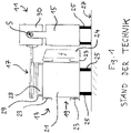
- the prior art device shown for processing food products comprises a product conveyor 11 and a working unit 13 in the form of an automatic packaging machine.
- the product conveyor 11 comprises a base frame or frame 15 and a conveyor unit 17 fixed to the frame 15.
- the conveyor unit 17 comprises one or more band or belt conveyors and is arranged on the frame 15 so as to project laterally as shown.
- the working unit 13 is located below the conveyor unit 17 and also comprises a base frame or frame 19, which is composed here of cross members 21 with profile-like side members 23 attached thereto. at the in 1
- a supply and control unit 24 in the form of a switch cabinet is mounted on the right side of the frame 19 of the working unit 13 . Both the product conveyor 11 and the working unit 13 are supported by feet 25 parked on floor 27.
- the device shown is integrated into a production line for packaged foods and is used to pack product portions that have been sliced by a high-performance slicer (not shown).
- the product conveyor 11 is accordingly intended to convey delivered product portions in a conveying direction running at right angles to the plane of the drawing and to insert them into an arrangement of packaging provided by the working unit 13 .
- the working unit 13 provides an arrangement of packaging trays at a transfer section 28 from a provided plastic film web by means of a deep-drawing process. After the product portions have been inserted, the packaging cavities are sealed with a web of plastic film that is also provided.
- a protective cover 29 is located above the transfer section 28.
- a housing 30 of the conveyor unit 17 is mounted on the frame 15 so that it can pivot about a pivot axis S. It can thus, starting from the in 1 illustrated lowered operating position to the in 2 shown raised maintenance position are pivoted.
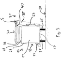
- the product conveyor 31 and the working unit 13 are not designed as machines to be set up separately, but are fused into one unit.
- the frame 35 of the product conveyor 31 is secured to the process unit 13 in spaced relation to the base 27 as shown. That is, the product conveyor 31 is carried entirely by the working unit 13 and is supported thereon in both horizontal and vertical directions.
- the mass and rigidity of the working unit 13 is sufficient to provide stability to the entire unit.
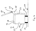
- the conveyor unit 37 of the product conveyor 31 is in Figures 3 to 5 illustrated embodiment of the invention also pivotable between a lowered operating position and a raised maintenance position.
- the conveyor unit 37 is designed here as a tape cassette in which the shafts of the corresponding tape or belt conveyor are mounted. A pivotable housing of the conveyor unit 37 can thus be dispensed with.
- a protective cover 39 is arranged above the transfer section 28 of the process cartridge 13 . If necessary, however, the protective cover 39 can be attached or attachable to the underside 40 of the conveyor unit 37 so that it can be pivoted together with this between the operating position and the maintenance position ( figure 5 ). In the event of maintenance, one work step can be saved.
- the protective cover 39 is used in the in Figures 3 to 5 illustrated device according to the invention additionally as a collecting device for collecting those particles that fall from the conveyor unit 37. The working unit 13 is thus also protected from cleaning fluid if the product conveyor 31 has to be intensively cleaned at regular intervals for reasons of hygiene.
- a variant of this embodiment is in 3 indicated by a dashed line.
- this variant is not shown for the sake of simplicity.
- the frame 35 has an arm 67 designed as a horizontally projecting frame area.
- the arm 67 extends from the vertically extending frame area on one side of the working unit 13, extends along the underside of the working unit 13 to the opposite side and is there fixed.
- the working unit 13 is encompassed by the frame 35, in particular in the manner of a clamp.
- the Figures 6 to 8 show a device not according to the invention for processing food products.
- the device also comprises a product conveyor 41 and a working unit 13, but differs from the embodiment described above in that the frame 45 of the product conveyor 41 is designed as a supporting frame.
- the frame 45 of the product conveyor 41 includes a vertical support section 47 and a horizontal standing section 49.
- the frame 45 therefore has a substantially L-shaped cross section, as can be seen in the figures.
- the width of the standing section 49 is greater than the width of the conveyor unit 37 projecting laterally, so that sufficient stability is ensured for the product conveyor 41 .
- the standing section 49 has only a small overall height, so that it can be arranged reaching into the free space 60 formed between the standing feet 25 of the working unit 13 . So although the product conveyor 41 is stable on its own, the width of the entire device can be compared to that in 1 and 2 shown arrangement can be reduced. If required, the standing section 49 can be attached to the working unit 13 according to the invention for additional stabilization.
- the conveyor unit 37 is designed as a tape cassette and between a lowered operating position ( 6 ) and a raised maintenance position ( 7 and 8th ) pivotable.
- the protective cover 39 can in turn be attached or attachable to the underside 40 of the conveyor unit 37 .
- the frame 55 of the product conveyor 51 is supported both on the floor 27 and on the working unit 13 .
- the frame 55 is fastened to one of the side supports 23 by means of a connecting element 65, for example screwed onto it. Due to this attachment, the frame 55 does not necessarily have to be stable in itself, so that it can be designed to be lighter and smaller accordingly.
- the conveyor unit 37 is designed as a tape cassette and between a lowered operating position ( 9 ) and a raised service position ( 10 ) pivotable.
- the protective cover 39 can in turn be fastened to the underside 40 of the conveyor unit 37 if required, which is 9 and 10 however, is not shown.
- the working unit 13 By including the working unit 13 to be arranged under the conveyor unit 37 in the supporting structure of the frame 35, 45, 55 of the product conveyor 31, 41, 51 - be it in the form of a direct mechanical supporting connection and/or through the targeted use of a free space defined by the working unit 13 - a much lighter and more compact construction can be achieved for the processing device as a whole.
Landscapes
- Engineering & Computer Science (AREA)
- Mechanical Engineering (AREA)
- Branching, Merging, And Special Transfer Between Conveyors (AREA)
- Chain Conveyers (AREA)
- Auxiliary Devices For And Details Of Packaging Control (AREA)
- General Preparation And Processing Of Foods (AREA)
- Intermediate Stations On Conveyors (AREA)
- Manufacturing And Processing Devices For Dough (AREA)
Description
- Die vorliegende Erfindung betrifft eine Vorrichtung zur Verarbeitung von Lebensmittelprodukten gemäß Anspruch 1.
- Bei der industriellen Verarbeitung von Lebensmittelprodukten, wie beispielsweise Fleisch-, Wurst- oder Käseprodukten, kommen häufig sogenannte Produktionslinien zum Einsatz, welche neben einer Schneidvorrichtung wie einem Hochleistungsslicer mehrere aneinander gereihte Fördereinrichtungen wie Portionierförderer, Aufreihförderer, Spreizförderer, Verteilerförderer, Pufferförderer und Einlegeförderer umfassen. Am Ende einer solchen Produktionslinie befindet sich üblicherweise eine Verpackungsmaschine, welche aus einer bereitgestellten Kunststofffolienbahn mittels eines Tiefziehprozesses eine Anordnung von Verpackungen zur Verfügung stellt, in welche die Produkte oder Produktportionen mittels eines Einlegeförderers in der Regel formatsatzweise eingelegt werden. Eine solche Verpackungsmaschine mit Tiefzieh-Einheit wird auf dem Fachgebiet auch als "Tiefzieher" bezeichnet. Ebenso wird der Einlegeförderer häufig verkürzt als "Einleger" bezeichnet. Um ein zuverlässiges Einlegen zu ermöglichen, muss der Einleger oberhalb des Tiefziehers positioniert sein, was bei seitlich auskragender Anordnung der Fördereinheit problemlos möglich ist.
- In der
DE 102 38 482 A1 ist eine Vorrichtung zum Einlegen von Gütern in eine Verpackungsmaschine oder dergleichen offenbart. Die Vorrichtung weist eine Fördervorrichtung für die Güter auf. Zumindest ein Teil der Fördervorrichtung ist um eine Schwenkachse schwenkbar. - Unter einer "Vorrichtung zur Verarbeitung von Lebensmittelprodukten" im Sinne der Erfindung soll allgemein eine beliebige Einrichtung zu verstehen sein, welche einer Verarbeitung, Bearbeitung und/oder Handhabung von einzelnen oder portionierten Lebensmittelprodukten dient. Ferner versteht sich, dass eine Anordnung aus einem Produktförderer mit seitlich auskragender Fördereinheit und einer zumindest teilweise unter der Fördereinheit angeordneten Arbeitseinheit in vielfältiger Weise im Umfeld der Lebensmittelbe- und -verarbeitung eingesetzt werden kann, also nicht nur in Form einer Kombination aus Einleger und Tiefzieher.
- In den meisten praktischen Fällen müssen die Fördereinheiten eines Einlegers für eine formatsatzweise Förderung tauglich sein und daher eine Arbeitsbreite von 40 cm bis 80 cm aufweisen, also relativ stark seitlich auskragen. Die Konstruktion muss ferner ausreichend starr sein, da im Betrieb Schwingungen, die eine ordnungsgemäße Ausrichtung der Produkte oder Portionen beeinträchtigen könnten, nicht akzeptierbar sind. Gleichzeitig muss eine gute Zugänglichkeit aller Maschinenbereiche für Reinigungs- und Wartungsarbeiten gewährleistet sein. Insbesondere das relativ große Tiefziehwerkzeug muss nach oben und zur Seite hin ein - und ausgebaut werden können. Aufgrund der konstruktionsbedingten Kopflastigkeit müssen die Rahmen außerdem im Allgemeinen eine hohe Standfestigkeit aufweisen, weshalb sie dementsprechend schwer sind - häufig bis zu mehreren Tonnen.
- Auf dem Fachgebiet sucht man daher fortlaufend nach Möglichkeiten, Lebensmittelverarbeitungsvorrichtungen kompakter und leichter zu bauen.
- Die Lösung dieser Aufgabe erfolgt durch eine Vorrichtung mit den Merkmalen des Anspruchs 1.
- Erfindungsgemäß ist der Rahmen des Produktförderers über eine mechanische Verbindung an der Arbeitseinheit abgestützt oder gehalten. Insbesondere ist der Rahmen außerdem an der Arbeitseinheit fixiert. In mechanischer Hinsicht wird also der Produktförderer in die Arbeitseinheit integriert. Somit können die Masse und die Steifigkeit bzw. Stabilität der Arbeitseinheit dazu genutzt werden, dem Rahmen des Produktförderers zusätzliche Standfestigkeit zu verleihen. Im Ergebnis ermöglicht dies eine leichtere und kompaktere Bauweise für den Produktförderer. Die Erfindung beruht unter anderem auf der Erkenntnis, dass es in vielen Anwendungssituationen der vorstehend genannten Art nicht erforderlich ist, die Arbeitseinheit und den Produktförderer als eigenständige standfeste Maschinen auszulegen, da sie ohnehin stets gemeinsam verwendet werden. Demgegenüber ist man auf dem Fachgebiet bislang dem Gedanken verhaftet, beispielsweise für Tiefzieher und Einleger völlig separate Konstruktionen vorzusehen.
- Insgesamt liegt der Erfindung also der allgemeine Gedanke zugrunde, eine unter einem Produktförderer mit seitlich auskragender Fördereinheit anzuordnende Arbeitseinheit dazu zu nutzen, den Produktförderer selbst kompakter und leichter zu bauen. Erfindungsgemäß kann die Masse, Steifigkeit oder Stabilität und/oder der umbaute Raum der Arbeitseinheit dazu genutzt werden, die Abstützung des Produktförderers zu verbessern. Hierfür ist es erforderlich, bereits bei der Konstruktion eines Produktförderers die später unter dessen Fördereinheit anzuordnende Arbeitseinheit zu berücksichtigen.
- Je nach Bedarf kann der Rahmen des Produktförderers in horizontaler und/oder in vertikaler Richtung an der Arbeitseinheit abgestützt sein. Eine Abstützung in horizontaler und in vertikaler Richtung ermöglicht eine besonders hohe Stabilität der Gesamtvorrichtung. Insbesondere ist der Rahmen mit zumindest einem horizontalen Rahmenbereich und/oder mit wenigstens einem vertikalen Rahmenbereich an der Arbeitseinheit abgestützt.
- Eine spezielle Ausführungsform der Erfindung sieht vor, dass der Produktförderer vollständig durch die Arbeitseinheit getragen ist. Dies bedeutet eine Abkehr von dem gängigen Prinzip, Produktförderer stets als eigenständige Vorrichtungen zu konstruieren. Letztlich wird bei der genannten Ausgestaltung also eine Arbeitseinheit mit integriertem Produktförderer, also beispielsweise ein Tiefzieher mit einem integrierten Einleger, bereitgestellt.
- Der Rahmen des Produktförderers kann in Beabstandung von einer Standfläche und/oder vom Boden an der Arbeitseinheit befestigt sein. Das heißt der Produktförderer kann ausschließlich über die Arbeitseinheit auf der Standfläche bzw. am Boden abgestützt sein. Der Verzicht auf eigene Standfüße für den Produktförderer ermöglicht eine beträchtliche Einsparung von Gewicht und Bauraum. Außerdem stellt sich eine Lebensmittelverarbeitungsmaschine mit wenigen Standfüßen als besonders reinigungsfreundlich dar.
- Alternativ kann der Rahmen des Produktförderers sowohl an einer Standfläche und/oder am Boden als auch an der Arbeitseinheit abgestützt sein. Dies ermöglicht eine besonders stabile Gesamtkonstruktion.
- Eine bevorzugte Ausgestaltung der Erfindung sieht vor, dass der Rahmen des Produktförderers allein nicht für ein standfestes Tragen der Fördereinheit ausreicht, d.h. dass der Rahmen nur zusammen mit der Arbeitseinheit eine ausreichende Steifigkeit und Standfestigkeit zum Tragen und Betreiben der Fördereinheit bereitstellt. Mit anderen Worten ist der Produktförderer lediglich mit einem leichten Rahmen ausgestattet, um Gewicht, Kosten und Bauraum zu sparen. Die gewünschte Standsicherheit ergibt sich erst durch die Abstützung an der Arbeitseinheit und Ausnutzung von deren Masse und Steifigkeit bzw. Stabilität.
- Eine weitere Ausführungsform der Erfindung sieht vor, dass der Rahmen des Produktförderers an einem, insbesondere seitlichen, Halterahmen der Arbeitseinheit fixiert ist. Beispielsweise kann der Rahmen des Produktförderers an einem Rahmen der Arbeitseinheit eingehängt oder angeschraubt sein. Viele Arbeitseinheiten weisen von außen zugängliche Rahmenelemente wie Profilträger auf, die für eine Anbringung des Rahmens des Produktförderers genutzt werden können.
- Es kann vorgesehen sein, dass die Fördereinheit des Produktförderers in Bezug auf dessen Rahmen zwischen einer abgesenkten Betriebsstellung und einer angehobenen Wartungsstellung bewegbar ist. Wenn sich die Fördereinheit in der angehobenen Wartungsstellung befindet, ist ein leichter und sicherer Zugang zu der darunter befindlichen Arbeitseinheit gewährleistet, beispielsweise zum Auswechseln eines Tiefziehwerkzeugs. Es ist hierbei nicht erforderlich, den Produktförderer als Ganzes beiseite zu schaffen oder aufwändige Montagearbeiten durchzuführen.
- Die Fördereinheit des Produktförderers kann von der Arbeitseinheit, insbesondere durch Verschwenken oder Wegklappen, weg bewegbar sein.
- Zwischen der Fördereinheit des Produktförderers und dem Rahmen kann eine Gelenkverbindung vorgesehen sein, die bei stationärem Rahmen ein Verschwenken oder Wegklappen der Fördereinheit relativ zum Rahmen erlaubt, insbesondere um eine parallel zur Förderrichtung verlaufenden Schwenkachse.
- Eine weitere Ausgestaltung der Erfindung sieht vor, dass eine Funktionseinheit der Arbeitseinheit gemeinsam mit der Fördereinheit bewegbar ist, wobei, bevorzugt, die Funktionseinheit an einer Unterseite, im unteren Bereich und/der unterhalb der Fördereinheit befestigt ist. Bei der Funktionseinheit kann es sich beispielsweise um eine Schutzabdeckung der Arbeitseinheit handeln, welche im Wartungsfall zu entfernen ist. Dadurch dass eine solche Schutzabdeckung gemeinsam mit der Fördereinheit zum Beispiel zwischen einer Betriebsstellung und einer Wartungsstellung bewegbar ist, entfällt für einen Benutzer das separate Entfernen der Schutzabdeckung. Zudem kann hierdurch in allen Betriebsstellungen dauerhaft gewährleistet werden, dass Produktreste oder Reinigungsmitteltropfen nicht nach unten in den Bereich der Arbeitseinheit gelangen. Die Handhabung der Vorrichtung kann somit vereinfacht und deren Sauberkeit weiter verbessert werden.
- Vorzugsweise stellt die Funktionseinheit in einer Betriebsstellung eine Betriebsfunktion der Arbeitseinheit und gleichzeitig eine Betriebsfunktion der Fördereinheit bereit. Beispielsweise kann die Funktionseinheit eine Schutzabdeckung für einen Tiefzieher und gleichzeitig eine Auffangvorrichtung zum Abweisen oder Auffangen von Partikeln bilden, welche von der darüber befindlichen Fördereinheit herabfallen. Demgegenüber ist es bei einer separaten Konstruktion von Tiefzieher und Einleger im Allgemeinen erforderlich, sowohl den Tiefzieher mit einer Schutzabdeckung als auch den Einleger im Bereich unterhalb der Fördereinheit mit einem Auffangblech oder dergleichen zu versehen.
- Wie erwähnt umfasst die Arbeitseinheit eine Einrichtung oder Teile einer Einrichtung zum automatischen Verpacken der geförderten Produkte, beispielsweise einen sogenannten Tiefzieher. Grundsätzlich kann die Arbeitseinheit jedoch weitere Einrichtungen zum Be- und Verarbeiten der geförderten Lebensmittelprodukte aufweisen. Der Produktförderer ist zum Einlegen der geförderten Produkte in jeweilige, durch die Einrichtung zum automatischen Verpacken bereitgestellte Verpackungseinheiten ausgebildet. Eine derart gestaltete Vorrichtung bildet also eine Einheit aus einer Verpackungsmaschine und einem dazugehörigen Einlegeförderer. Derartige Einheiten werden im Umfeld der Lebensmittelverarbeitung häufig benötigt und brauchen erfindungsgemäß aufgrund des modularen Aufbaus aus Produktförderer einerseits und Arbeitseinheit andererseits erst vor Ort direkt am Aufstellort erstellt zu werden. Zusätzlich kann der Produktförderer zum Gruppieren von Produkten oder mehrere Einzelprodukte umfassenden Portionen, zum Bilden von Zeilen aus Produkten oder mehrere Einzelprodukte umfassenden Portionen, und/oder zum Bilden von Formatsätzen aus Produkten oder mehrere Einzelprodukte umfassenden Portionen ausgebildet sein.
- Gemäß einem Ausführungsbeispiel ist vorgesehen, dass Positionierungsmittel vorgesehen sind, mittels welcher die Position des Rahmens, insbesondere von horizontalen und/oder vertikalen Rahmenbereichen, relativ zu der Arbeitseinheit, insbesondere bei an der Arbeitseinheit abgestütztem oder gehaltenem Rahmen einstellbar und in einem jeweils eingestellten Zustand gehalten ist, wobei insbesondere die Positionierungsmittel in ihrer einen Abstand zwischen dem Rahmen und der Arbeitseinheit festlegenden Länge veränderlich sind. Hierdurch kann auf denkbar einfache Weise vor Ort eine Adaption des Produktförderers an die Arbeitseinheit bzw. an die jeweils gegebene Abstütz- bzw. Haltesituation vorgenommen werden. Beispielsweise können Elemente oder Teile des Rahmens, beispielsweise horizontal oder vertikal verlaufende Rahmenteile des Produktförderers in der Länge veränderlich sein, um den Produktförderer an die Arbeitseinheit bzw. an deren Mittel zum Abstützen oder Halten bzw. zum Fixieren des Produktförderers anzupassen.
- Des Weiteren kann vorgesehen sein, dass der Rahmen die Arbeitseinheit untergreift oder unterseitig umgreift, wobei insbesondere ein horizontal auskragender Rahmenbereich des Rahmens sich ausgehend von einer Seite der Arbeitseinheit unter dieser hindurch zur gegenüberliegenden Seite erstreckt und an dieser gegenüberliegenden Seite der Arbeitseinheit fixiert ist. Hierdurch kann eine besonders gleichmäßig verteilte Krafteinleitung in den Rahmen der Arbeitseinheit realisiert werden. Zudem können zusätzliche Standfüße für den Produktförderer entfallen, wodurch eine gute Reinigung des Bodens bzw. der Standfläche erleichtert wird.
- Weiterbildungen der Erfindung sind auch in den abhängigen Ansprüchen, der Beschreibung sowie den beigefügten Zeichnungen angegeben.
- Die Erfindung wird nachfolgend beispielhaft unter Bezugnahme auf die Zeichnungen beschrieben.
- Fig. 1
- zeigt eine gemäß dem Stand der Technik gestaltete Anordnung aus einem Produktförderer und einer Arbeitseinheit, wobei sich eine Fördereinheit des Produktförderers in einer abgesenkten Betriebsstellung befindet.
- Fig. 2
- zeigt die Anordnung gemäß
Fig. 1 , wobei sich die Fördereinheit in einer angehobenen Wartungsstellung befindet. - Fig. 3
- zeigt eine Vorrichtung zur Verarbeitung von Lebensmittelprodukten gemäß einer ersten Ausführungsform der Erfindung, wobei sich eine Fördereinheit eines Produktförderers der Vorrichtung in einer abgesenkten Betriebsstellung befindet.
- Fig. 4
- zeigt die Vorrichtung gemäß
Fig. 3 , wobei sich die Fördereinheit in einer angehobenen Wartungsstellung befindet. - Fig. 5
- zeigt die Vorrichtung gemäß
Fig. 4 , wobei eine Funktionseinheit einer Arbeitseinheit der Vorrichtung gemeinsam mit der Fördereinheit in die angehobene Wartungsstellung bewegt ist. - Fig. 6
- zeigt eine nicht zur Erfindung gehörende Vorrichtung zur Verarbeitung von Lebensmittelprodukten, wobei sich eine Fördereinheit eines Produktförderers der Vorrichtung in einer abgesenkten Betriebsstellung befindet.
- Fig. 7
- zeigt die Vorrichtung gemäß
Fig. 6 , wobei sich die Fördereinheit in einer angehobenen Wartungsstellung befindet. - Fig. 8
- zeigt die Vorrichtung gemäß
Fig. 7 , wobei eine Funktionseinheit einer Arbeitseinheit der Vorrichtung gemeinsam mit der Fördereinheit in die angehobene Wartungsstellung bewegt ist. - Fig. 9
- zeigt eine Vorrichtung zur Verarbeitung von Lebensmittelprodukten gemäß einer zweiten Ausführungsform der Erfindung, wobei sich eine Fördereinheit eines Produktförderers der Vorrichtung in einer abgesenkten Betriebsstellung befindet.
- Fig. 10
- zeigt die Vorrichtung gemäß
Fig. 9 , wobei sich die Fördereinheit in einer angehobenen Wartungsstellung befindet. - Die in
Fig. 1 und2 gezeigte, gemäß dem Stand der Technik gestaltete Vorrichtung zur Verarbeitung von Lebensmittelprodukten umfasst einen Produktförderer 11 und eine Arbeitseinheit 13 in Form einer automatischen Verpackungsmaschine. - Der Produktförderer 11 umfasst ein Grundgestell oder einen Rahmen 15 und eine am Rahmen 15 fixierte Fördereinheit 17. Die Fördereinheit 17 umfasst einen oder mehrere Band- oder Riemenförderer und ist wie dargestellt seitlich auskragend an dem Rahmen 15 angeordnet. Die Arbeitseinheit 13 befindet sich unterhalb der Fördereinheit 17 und umfasst ebenfalls ein Grundgestell oder einen Rahmen 19, welcher hier aus Querträgern 21 mit daran angebrachten, profilartigen Seitenträgern 23 zusammengesetzt ist. An der in
Fig. 1 rechten Seite des Rahmens 19 der Arbeitseinheit 13 ist eine Versorgungs- und Steuereinheit 24 in Form eines Schaltschranks angebracht. Sowohl der Produktförderer 11 als auch die Arbeitseinheit 13 sind mittels Standfüßen 25 auf dem Boden 27 abgestellt. - Die in
Fig. 1 und2 dargestellte Vorrichtung ist in eine Produktionslinie für abgepackte Lebensmittel integriert und dient dazu, von einem nicht dargestellten Hochleistungs-Slicer aufgeschnittene Produktportionen formatsatzweise zu verpacken. Der Produktförderer 11 ist demgemäß dazu vorgesehen, angelieferte Produktportionen in einer rechtwinklig zur Zeichnungsebene verlaufenden Förderrichtung zu fördern und diese in eine Anordnung von durch die Arbeitseinheit 13 bereitgestellten Verpackungen einzulegen. Die Arbeitseinheit 13 stellt an einem Übergabeabschnitt 28 aus einer bereitgestellten Kunststofffolienbahn mittels eines Tiefziehprozesses eine Anordnung von Verpackungsmulden zur Verfügung. Nach dem Einlegen der Produktportionen werden die Verpackungsmulden mit einer ebenfalls bereitgestellten Kunststofffolienbahn verschlossen. Oberhalb des Übergabeabschnitts 28 befindet sich eine Schutzabdeckung 29. - Um bei Umbau-, Reparatur- oder Wartungsarbeiten einen leichten und sicheren Zugang zu der Arbeitseinheit 13 zu gewährleisten, ist ein Gehäuse 30 der Fördereinheit 17 um eine Schwenkachse S verschwenkbar an dem Rahmen 15 gelagert. Sie kann somit ausgehend von der in
Fig. 1 dargestellten abgesenkten Betriebsstellung in die inFig. 2 dargestellte angehobene Wartungsstellung geschwenkt werden. - Bei der in
Fig. 3 bis 5 dargestellten erfindungsgemäßen Vorrichtung zur Verarbeitung von Lebensmittelprodukten sind der Produktförderer 31 sowie die Arbeitseinheit 13 nicht als separat aufzustellende Maschinen konzipiert, sondern zu einer Einheit verschmolzen. Speziell ist der Rahmen 35 des Produktförderers 31 wie dargestellt in Beabstandung von der Standfläche 27 an der Arbeitseinheit 13 befestigt. Das heißt der Produktförderer 31 ist vollständig durch die Arbeitseinheit 13 getragen und sowohl in horizontaler als auch in vertikaler Richtung an dieser abgestützt. Die Masse und die Steifigkeit der Arbeitseinheit 13 ist ausreichend, um der gesamten Einheit Standfestigkeit zu verleihen. Die Fördereinheit 37 des Produktförderers 31 ist bei der inFig. 3 bis 5 dargestellten Ausführungsform der Erfindung ebenfalls zwischen einer abgesenkten Betriebsstellung und einer angehobenen Wartungsstellung verschwenkbar. Die Fördereinheit 37 ist hier jedoch als Bandkassette ausgebildet, in welcher die Wellen des entsprechenden Band- oder Riemenförderers gelagert sind. Somit kann auf ein verschwenkbares Gehäuse der Fördereinheit 37 verzichtet werden. - Wie bei der in
Fig. 1 und2 dargestellten Ausführungsform ist eine Schutzabdeckung 39 oberhalb des Übergabeabschnitts 28 der Arbeitseinheit 13 angeordnet. Bei Bedarf kann die Schutzabdeckung 39 jedoch an der Unterseite 40 der Fördereinheit 37 befestigt oder befestigbar sein, sodass sie gemeinsam mit dieser zwischen der Betriebsstellung und der Wartungsstellung verschwenkbar ist (Fig. 5 ). Im Wartungsfall kann somit ein Arbeitsgang eingespart werden. Die Schutzabdeckung 39 dient bei der inFig. 3 bis 5 dargestellten erfindungsgemäßen Vorrichtung zusätzlich als Auffangvorrichtung zum Auffangen solcher Partikel, die von der Fördereinheit 37 herabfallen. Damit wird die Arbeitseinheit 13 auch vor Reinigungsfluid geschützt, wenn aus Hygienegründen der Produktförderer 31 in regelmäßigen Intervallen intensiv gereinigt werden muss. - Eine Variante dieses Ausführungsbeispiels ist in
Fig. 3 durch eine gestrichelte Linie angedeutet. InFig. 4 und5 ist diese Variante der Einfachheit halber nicht gezeigt. Gemäß dieser Variante besitzt der Rahmen 35 einen als horizontal auskragender Rahmenbereich ausgebildeten Arm 67. Der Arm 67 geht von dem sich vertikal erstreckenden Rahmenbereich an der einen Seite der Arbeitseinheit 13 aus, erstreckt sich an der Unterseite der Arbeitseinheit 13 entlang zur gegenüberliegenden Seite und ist dort fixiert. Auf diese Weise wird die Arbeitseinheit 13 vom Rahmen 35 insbesondere klammerartig umgriffen. Bei dieser Abstützung bzw. Halterung des Produktförderers 31 an der Arbeitseinheit 13 kann in vorteilhafter Weise eine besonders gleichmäßig verteilte Krafteinleitung über den Rahmen 35 des Produktförderers 31 in die Arbeitseinheit 13 erreicht werden. Zusätzliche Standfüße sind auch in dieser Variante nicht erforderlich. - Die
Fig. 6 bis 8 zeigen eine nicht erfindungsgemäße Vorrichtung zur Verarbeitung von Lebensmittelprodukten. Die Vorrichtung umfasst ebenfalls einen Produktförderer 41 sowie eine Arbeitseinheit 13, unterscheidet sich jedoch insofern von der vorstehend beschriebenen Ausführungsform, als der Rahmen 45 des Produktförderers 41 als tragendes Gestell ausgebildet ist. Speziell umfasst der Rahmen 45 des Produktförderers 41 einen vertikalen Tragabschnitt 47 sowie einen horizontalen Standabschnitt 49. Der Rahmen 45 weist also wie in den Figuren erkennbar einen im Wesentlichen L-förmigen Querschnitt auf. Die Breite des Standabschnitts 49 ist größer als die Breite der seitlich auskragenden Fördereinheit 37, sodass für den Produktförderer 41 eine ausreichende Standfestigkeit sichergestellt ist. Der Standabschnitt 49 weist jedoch nur eine geringe Bauhöhe auf, sodass er in den zwischen den Standfüßen 25 der Arbeitseinheit 13 gebildeten Freiraum 60 hineinreichend angeordnet werden kann. Obwohl also der Produktförderer 41 für sich genommen standfest ist, kann die Breite der Gesamtvorrichtung gegenüber der inFig. 1 und2 dargestellten Anordnung verringert werden. Bei Bedarf kann der Standabschnitt 49 zur zusätzlichen Stabilisierung erfindungsgemäß an der Arbeitseinheit 13 befestigt sein. - Wie bei der in
Fig. 3 bis 5 dargestellten Ausführungsform ist auch bei der inFig. 6 bis 8 dargestellten Ausführungsform die Fördereinheit 37 als Bandkassette ausgeführt und zwischen einer abgesenkten Betriebsstellung (Fig. 6 ) sowie einer angehobenen Wartungsstellung (Fig. 7 und8 ) verschwenkbar. GemäßFig. 8 kann die Schutzabdeckung 39 wiederum an der Unterseite 40 der Fördereinheit 37 befestigt oder befestigbar sein. - Bei der in
Fig. 9 und10 dargestellten weiteren Ausführungsform einer erfindungsgemäßen Vorrichtung zur Verarbeitung von Lebensmittelprodukten ist der Rahmen 55 des Produktförderers 51 sowohl am Boden 27 als auch an der Arbeitseinheit 13 abgestützt. Speziell ist der Rahmen 55 mittels eines Verbindungselements 65 an einem der Seitenträger 23 befestigt, beispielsweise an diesem angeschraubt. Aufgrund dieser Befestigung muss der Rahmen 55 nicht zwingend für sich genommen standfest sein, sodass er dementsprechend leichter und kleiner ausgelegt werden kann. Auch bei der inFig. 9 und10 dargestellten Ausführungsform ist die Fördereinheit 37 als Bandkassette ausgeführt und zwischen einer abgesenkten Betriebsstellung (Fig. 9 ) und einer angehobenen Wartungsstellung (Fig. 10 ) verschwenkbar. Die Schutzabdeckung 39 kann wiederum bei Bedarf an der Unterseite 40 der Fördereinheit 37 befestigt sein, was inFig. 9 und10 jedoch nicht dargestellt ist. - Durch das Einbeziehen der unter der Fördereinheit 37 anzuordnenden Arbeitseinheit 13 in die Stützkonstruktion des Rahmens 35, 45, 55 des Produktförderers 31, 41, 51 - sei es in Form einer direkten mechanischen Stützverbindung und/oder durch gezielte Nutzung eines durch die Arbeitseinheit 13 definierten Freiraums-kann eine wesentlich leichtere und kompaktere Bauweise für die Verarbeitungsvorrichtung als Ganzes erzielt werden.
-
- 11
- Produktförderer
- 13
- Arbeitseinheit
- 15
- Rahmen des Produktförderers
- 17
- Fördereinheit
- 19
- Rahmen der Arbeitseinheit
- 21
- Querträger
- 23
- Seitenträger
- 24
- Versorgungs- und Steuereinheit
- 25
- Standfuß
- 27
- Standfläche, Boden
- 28
- Übergabeabschnitt
- 29
- Schutzabdeckung
- 30
- Gehäuse
- 31
- Produktförderer
- 35
- Rahmen des Produktförderers
- 37
- Fördereinheit
- 39
- Schutzabdeckung
- 40
- Unterseite der Fördereinheit
- 41
- Produktförderer
- 45
- Rahmen des Produktförderers
- 47
- Tragabschnitt
- 49
- Standabschnitt
- 51
- Produktförderer
- 55
- Rahmen des Produktförderers
- 60
- Freiraum
- 65
- Verbindungselement
- 67
- Rahmenbereich, Arm
- S
- Schwenkachse
Claims (12)
- Vorrichtung zur Verarbeitung von Lebensmittelprodukten, die umfasst:einen Produktförderer (31, 51) mit einem Rahmen (35, 55) und einer Fördereinheit (37) zum Fördern von Produkten entlang einer Förderrichtung, wobei die Fördereinheit (37) bezüglich der Förderrichtung seitlich auskragend an dem Rahmen (35, 55) angeordnet ist, undeine die Verarbeitung der geförderten Produkte betreffende Arbeitseinheit (13), die zumindest teilweise unter der auskragenden Fördereinheit (37) des Produktförderers (31, 51) angeordnet ist,dadurch gekennzeichnet, dassder Rahmen (35, 55) des Produktförderers (31, 51) über eine mechanische Verbindung an der Arbeitseinheit (13) abgestützt oder gehalten, und insbesondere fixiert, ist,die Arbeitseinheit (13) eine Einrichtung oder Teile einer Einrichtung zum automatischen Verpacken der geförderten Produkte umfasst, undder Produktförderer (31, 51) zum Einlegen der geförderten Produkte in jeweilige, durch die Einrichtung zum automatischen Verpacken bereitgestellte Verpackungseinheiten ausgebildet ist.
- Vorrichtung nach Anspruch 1,
dadurch gekennzeichnet, dass
der Rahmen (35, 55) des Produktförderers (31, 51) in horizontaler und/oder in vertikaler Richtung an der Arbeitseinheit (13) abgestützt ist, wobei insbesondere der Rahmen (35, 55) mit einem horizontalen Rahmenbereich und/oder mit einem vertikalen Rahmenbereich an der Arbeitseinheit (13) fixiert ist. - Vorrichtung nach Anspruch 1 oder 2,
dadurch gekennzeichnet, dass
der Produktförderer (31) vollständig durch die Arbeitseinheit (13) getragen ist, wobei insbesondere der Rahmen (35) des Produktförderers (31) in Beabstandung von einer Standfläche (27) an der Arbeitseinheit (13) befestigt ist. - Vorrichtung nach Anspruch 1 oder 2,
dadurch gekennzeichnet, dass
der Rahmen (55) des Produktförderers (51) sowohl an einer Standfläche (27) als auch an der Arbeitseinheit (13) abgestützt ist, wobei insbesonderedass der Rahmen (55) des Produktförderers (51) nur zusammen mit der Arbeitseinheit (13) eine ausreichende Steifigkeit und Standfestigkeit zum Tragen und Betreiben der Fördereinheit (37) bereitstellt. - Vorrichtung nach einem der vorstehenden Ansprüche,
dadurch gekennzeichnet, dass
der Rahmen (35, 55) des Produktförderers (31, 51) an einem, insbesondere seitlichen, Halterahmen (23) der Arbeitseinheit (13) fixiert ist, und/oder dass die Fördereinheit (37) des Produktförderers (31, 41, 51) in Bezug auf dessen Rahmen (35, 45, 55) zwischen einer abgesenkten Betriebsstellung und einer angehobenen Wartungsstellung bewegbar ist. - Vorrichtung nach einem der vorstehenden Ansprüche,
dadurch gekennzeichnet, dass
die Fördereinheit (37) des Produktförderers (31, 41, 51) von der Arbeitseinheit (13), insbesondere durch Verschwenken oder Wegklappen, weg bewegbar ist. - Vorrichtung nach einem der vorstehenden Ansprüche,
dadurch gekennzeichnet, dass
zwischen der Fördereinheit (37) des Produktförderers (31, 41, 51) und dem Rahmen (35, 45, 55) eine Gelenkverbindung vorgesehen ist, die bei stationärem Rahmen (35, 45, 55) ein Verschwenken oder Wegklappen der Fördereinheit (37) relativ zum Rahmen (35, 45, 55) erlaubt, insbesondere um eine parallel zur Förderrichtung verlaufenden Schwenkachse (S). - Vorrichtung nach einem der Ansprüche 5 bis 7,
dadurch gekennzeichnet, dass
eine Funktionseinheit (39) der Arbeitseinheit (13) gemeinsam mit der Fördereinheit (13) bewegbar ist, wobei, bevorzugt, die Funktionseinheit (39) an einer Unterseite (40), im unteren Bereich und/oder unterhalb der Fördereinheit (37) fixiert ist, und/oder dass die Funktionseinheit (39) in einer Betriebsstellung eine Betriebsfunktion der Arbeitseinheit (13) und gleichzeitig eine Betriebsfunktion der Fördereinheit (37) bereitstellt. - Vorrichtung nach einem der vorstehenden Ansprüche,
dadurch gekennzeichnet, dass
die Arbeitseinheit (13) als Tiefzieheinrichtung oder als ein Bestandteil einer Tiefzieheinrichtung ausgebildet ist. - Vorrichtung nach einem der vorstehenden Ansprüche,
dadurch gekennzeichnet, dass
der Produktförderer (31, 41, 51) zum Gruppieren von Produkten oder mehrere Einzelprodukte umfassenden Portionen, zum Bilden von Zeilen aus Produkten oder mehrere Einzelprodukte umfassenden Portionen und/oder zum Bilden von Formatsätzen aus Produkten oder mehrere Einzelprodukte umfassenden Portionen, ausgebildet ist. - Vorrichtung nach einem der vorstehenden Ansprüche,
dadurch gekennzeichnet, dass
Positionierungsmittel vorgesehen sind, mittels welcher die Position des Rahmens (35, 45, 55), insbesondere von horizontalen und/oder vertikalen Rahmenbereichen, relativ zu der Arbeitseinheit (13), insbesondere bei an der Arbeitseinheit (13) abgestütztem oder gehaltenem Rahmen (35, 45, 55), einstellbar und in einem jeweils eingestellten Zustand gehalten ist, wobei insbesondere die Positionierungsmittel in ihrer einen Abstand zwischen dem Rahmen (35, 45, 55) und der Arbeitseinheit (13) festlegenden Länge veränderlich sind. - Vorrichtung nach einem der vorstehenden Ansprüche,
dadurch gekennzeichnet, dass
der Rahmen (35) die Arbeitseinheit (13) untergreift oder unterseitig umgreift, wobei insbesondere ein horizontal auskragender Rahmenbereich (67) des Rahmens (35) sich ausgehend von einer Seite der Arbeitseinheit (13) unter dieser hindurch zur gegenüberliegenden Seite erstreckt und an dieser gegenüberliegenden Seite der Arbeitseinheit (13) fixiert ist.
Priority Applications (1)
| Application Number | Priority Date | Filing Date | Title |
|---|---|---|---|
| PL15161101.9T PL2923955T5 (pl) | 2014-03-28 | 2015-03-26 | Urządzenie do przetwórstwa produktów spożywczych |
Applications Claiming Priority (1)
| Application Number | Priority Date | Filing Date | Title |
|---|---|---|---|
| DE102014104387.1A DE102014104387A1 (de) | 2014-03-28 | 2014-03-28 | Vorrichtung zur Verarbeitung von Lebensmittelprodukten |
Publications (4)
| Publication Number | Publication Date |
|---|---|
| EP2923955A2 EP2923955A2 (de) | 2015-09-30 |
| EP2923955A3 EP2923955A3 (de) | 2015-12-09 |
| EP2923955B1 EP2923955B1 (de) | 2016-10-19 |
| EP2923955B2 true EP2923955B2 (de) | 2022-11-30 |
Family
ID=52780880
Family Applications (1)
| Application Number | Title | Priority Date | Filing Date |
|---|---|---|---|
| EP15161101.9A Active EP2923955B2 (de) | 2014-03-28 | 2015-03-26 | Vorrichtung zur verarbeitung von lebensmittelprodukten |
Country Status (5)
| Country | Link |
|---|---|
| US (3) | US11383935B2 (de) |
| EP (1) | EP2923955B2 (de) |
| DE (1) | DE102014104387A1 (de) |
| ES (1) | ES2611578T5 (de) |
| PL (1) | PL2923955T5 (de) |
Families Citing this family (3)
| Publication number | Priority date | Publication date | Assignee | Title |
|---|---|---|---|---|
| DE102017106898B4 (de) | 2017-03-30 | 2023-03-02 | Multivac Sepp Haggenmüller Se & Co. Kg | Verpackungsmaschine mit stapelbaren Schutzabdeckungen |
| DE102017108991A1 (de) | 2017-04-26 | 2018-10-31 | Weber Maschinenbau Gmbh Breidenbach | Verpacken von lebensmittelprodukten |
| DE102017125110A1 (de) | 2017-10-26 | 2019-05-02 | Weber Maschinenbau Gmbh Breidenbach | Fördereinrichtung |
Citations (2)
| Publication number | Priority date | Publication date | Assignee | Title |
|---|---|---|---|---|
| EP1854596A1 (de) † | 2006-05-12 | 2007-11-14 | Ermatec | Vorrichtung zum Aufschneiden von Lebensmittelprodukten und daran angebundene Verpackungsmaschine |
| US20120159900A1 (en) † | 2010-12-22 | 2012-06-28 | Giorgio Grasselli | Apparatus for laying sliced foods into containers |
Family Cites Families (28)
| Publication number | Priority date | Publication date | Assignee | Title |
|---|---|---|---|---|
| US3561512A (en) * | 1968-04-15 | 1971-02-09 | Ward Foods Inc | Pineapple-treating apparatus |
| GB1512509A (en) * | 1974-05-23 | 1978-06-01 | Shell Bv | Fungicides |
| US4034536A (en) | 1976-06-11 | 1977-07-12 | Mahaffy & Harder Engineering Company | Packaging apparatus and techniques |
| US4548108A (en) * | 1983-08-08 | 1985-10-22 | Cashin Systems Corporation | Slicing machine |
| CA2051643C (en) * | 1989-04-07 | 1999-12-28 | Andrew James Watters | Continuous feed thermoforming method and apparatus |
| GB2241682B (en) | 1990-03-05 | 1993-11-03 | Arnott Handling Equipment Limi | Conveyor assembly |
| US5271304A (en) * | 1990-07-03 | 1993-12-21 | Carruthers Equipment Co. | Automatic food slicing machine |
| CH683176A5 (de) | 1991-04-25 | 1994-01-31 | Buehler S A R L | Bandförderer. |
| BR9306279A (pt) * | 1992-04-23 | 1998-06-30 | Townsend Engineering Co | Máquina fatiadora de carne e processo para a sua utilização |
| DE4218720A1 (de) * | 1992-06-06 | 1993-12-09 | Bielomatik Leuze & Co | Schließvorrichtung für Packgut-Umhüllungen |
| DE4334238A1 (de) * | 1993-10-04 | 1995-04-06 | Stimpfl Christof | Vorrichtung zum Verpacken von Gegenständen |
| US5444750A (en) * | 1993-11-09 | 1995-08-22 | Bass Gambling Supplies Inc. | Tally punch machine |
| DE4407639A1 (de) | 1994-03-08 | 1995-09-14 | Tetra Laval Convenience Food | Verfahren und Tiefzieheinrichtung zum Herstellen einer Folienschale |
| WO1995029846A1 (de) * | 1994-05-03 | 1995-11-09 | Inauen Maschinen Ag | Vakuum-verpackungsmaschine |
| US5499719A (en) | 1995-02-13 | 1996-03-19 | Formax, Inc. | Takeaway/correction conveyor system for food product machine |
| DE29718630U1 (de) * | 1997-10-21 | 1997-12-11 | RÜHLE GmbH, 79865 Grafenhausen | Würfel- und Streifenschneidemaschine |
| FR2771080B1 (fr) | 1997-11-18 | 2000-01-28 | Sogem Agro | Convoyeur a bande sans fin motorisee |
| DE29801161U1 (de) * | 1998-01-24 | 1998-03-05 | Magurit Gefrierschneider GmbH, 42897 Remscheid | Zerkleinerungsvorrichtung für Nahrungsmittel |
| FR2821833A1 (fr) | 2001-03-06 | 2002-09-13 | Bernard Jean Michel Philippe | Convoyeur a bande |
| US6585477B1 (en) * | 2001-06-22 | 2003-07-01 | Lawrence Equipment | Counter-stacker for flat food products |
| DE10143506A1 (de) | 2001-09-05 | 2003-05-08 | Weber Maschb Gmbh & Co Kg | Verteilervorrichtung |
| DE10201182A1 (de) | 2002-01-14 | 2003-07-24 | Cfs Gmbh Kempten | Positioniersystem |
| DE10238482A1 (de) * | 2002-05-23 | 2003-12-04 | Cfs Kempten Gmbh | Einlegevorrichtung |
| DE102006020368A1 (de) | 2006-02-09 | 2007-08-16 | Cfs Germany Gmbh | Verpackungsmaschine mit einer Kettenreinigung |
| DE102006006523A1 (de) | 2006-02-10 | 2007-08-16 | Cfs Germany Gmbh | Verpackungsmaschine mit zwei hintereinander angeordneten Transportketten |
| DE102008015689A1 (de) * | 2008-03-26 | 2009-10-01 | Multivac Sepp Haggenmüller Gmbh & Co. Kg | Verpackungsmaschine |
| DE102010034676A1 (de) | 2010-08-18 | 2012-02-23 | Weber Maschinenbau Gmbh Breidenbach | Fördern von Gegenständen |
| DE102011101101A1 (de) * | 2011-05-10 | 2014-01-30 | Bizerba Gmbh & Co Kg | Schneidemaschine |
-
2014
- 2014-03-28 DE DE102014104387.1A patent/DE102014104387A1/de active Pending
-
2015
- 2015-03-26 PL PL15161101.9T patent/PL2923955T5/pl unknown
- 2015-03-26 ES ES15161101T patent/ES2611578T5/es active Active
- 2015-03-26 US US14/669,548 patent/US11383935B2/en active Active
- 2015-03-26 EP EP15161101.9A patent/EP2923955B2/de active Active
-
2022
- 2022-02-04 US US17/665,029 patent/US20220153527A1/en not_active Abandoned
-
2025
- 2025-11-21 US US19/396,969 patent/US20260077956A1/en active Pending
Patent Citations (2)
| Publication number | Priority date | Publication date | Assignee | Title |
|---|---|---|---|---|
| EP1854596A1 (de) † | 2006-05-12 | 2007-11-14 | Ermatec | Vorrichtung zum Aufschneiden von Lebensmittelprodukten und daran angebundene Verpackungsmaschine |
| US20120159900A1 (en) † | 2010-12-22 | 2012-06-28 | Giorgio Grasselli | Apparatus for laying sliced foods into containers |
Also Published As
| Publication number | Publication date |
|---|---|
| PL2923955T5 (pl) | 2023-03-27 |
| EP2923955B1 (de) | 2016-10-19 |
| EP2923955A3 (de) | 2015-12-09 |
| US20150274431A1 (en) | 2015-10-01 |
| PL2923955T3 (pl) | 2017-05-31 |
| US20260077956A1 (en) | 2026-03-19 |
| US11383935B2 (en) | 2022-07-12 |
| ES2611578T5 (es) | 2023-02-17 |
| US20220153527A1 (en) | 2022-05-19 |
| DE102014104387A1 (de) | 2015-10-01 |
| EP2923955A2 (de) | 2015-09-30 |
| ES2611578T3 (es) | 2017-05-09 |
Similar Documents
| Publication | Publication Date | Title |
|---|---|---|
| EP3476774B1 (de) | Fördereinrichtung | |
| EP3315423B1 (de) | Tiefziehverpackungsmaschine | |
| EP3578933B1 (de) | Wäge-fördervorrichtung | |
| EP3315420B1 (de) | Tiefziehverpackungsmaschine | |
| WO2016102417A1 (de) | Vorrichtung zum bewegen von objekten | |
| EP2936986B1 (de) | Schaschlikmaschine und verfahren zum herstellen von schaschlikspiessen | |
| EP3025971B1 (de) | Füll- und wechselvorrichtung zum befüllen von behältern mit schüttgut | |
| EP2778079B1 (de) | Tiefziehverpackungsmaschine mit integrierter Produktzuführung | |
| DE2930150C2 (de) | Transportvorrichtung an einer Verpackungsmaschine mit mehreren, in einem Maschinengestell nebeneinander angeordneten Endlosförderern | |
| CH704718A1 (de) | Vorrichtung zum Beschicken einer Förderanlage mit einer grossen Menge von Teilen. | |
| EP2923955B2 (de) | Vorrichtung zur verarbeitung von lebensmittelprodukten | |
| WO2005075293A1 (de) | Verfahren und vorrichtung zum überführen von produkten aus einem vorratsgefäss in die näpfe einer folie | |
| EP3428079A1 (de) | Tiefziehverpackungsmaschine mit flexibler packungsunterstützung | |
| DE102014106740A1 (de) | Vorrichtung zum Fördern von Lebensmittelprodukten | |
| EP3124387B1 (de) | Tiefziehverpackungsmaschine | |
| DE102015210052A1 (de) | Übergabevorrichtung und Verfahren | |
| EP2001747B1 (de) | Transporteinrichtung | |
| WO2016096850A1 (de) | Bewegungsvorrichtung mit abdeckung | |
| DE102013100806B4 (de) | Mehrspurige Fördervorrichtung | |
| DE102012108700A1 (de) | Verfahren zur Korrektur von Portionen in Verpackungsmulden | |
| EP3865432B1 (de) | Bandkörper mit einem eingreifschutz | |
| WO2022184457A1 (de) | Förderanlage zum fördern von fördergut | |
| EP3699118B1 (de) | Zuführeinrichtung für behälterteile zur verwendung an einer vorrichtung zum befüllen von behältern mit flüssigen bis pastösen nahrungsmitteln | |
| EP0483446A1 (de) | Schutzvorrichtung an einer Verpackungsmaschine | |
| EP3395696B1 (de) | Verpacken von lebensmittelprodukten |
Legal Events
| Date | Code | Title | Description |
|---|---|---|---|
| PUAI | Public reference made under article 153(3) epc to a published international application that has entered the european phase |
Free format text: ORIGINAL CODE: 0009012 |
|
| AK | Designated contracting states |
Kind code of ref document: A2 Designated state(s): AL AT BE BG CH CY CZ DE DK EE ES FI FR GB GR HR HU IE IS IT LI LT LU LV MC MK MT NL NO PL PT RO RS SE SI SK SM TR |
|
| AX | Request for extension of the european patent |
Extension state: BA ME |
|
| PUAL | Search report despatched |
Free format text: ORIGINAL CODE: 0009013 |
|
| AK | Designated contracting states |
Kind code of ref document: A3 Designated state(s): AL AT BE BG CH CY CZ DE DK EE ES FI FR GB GR HR HU IE IS IT LI LT LU LV MC MK MT NL NO PL PT RO RS SE SI SK SM TR |
|
| AX | Request for extension of the european patent |
Extension state: BA ME |
|
| RIC1 | Information provided on ipc code assigned before grant |
Ipc: B65B 9/04 20060101ALI20151030BHEP Ipc: B65B 35/24 20060101AFI20151030BHEP |
|
| 17P | Request for examination filed |
Effective date: 20160113 |
|
| RBV | Designated contracting states (corrected) |
Designated state(s): AL AT BE BG CH CY CZ DE DK EE ES FI FR GB GR HR HU IE IS IT LI LT LU LV MC MK MT NL NO PL PT RO RS SE SI SK SM TR |
|
| GRAP | Despatch of communication of intention to grant a patent |
Free format text: ORIGINAL CODE: EPIDOSNIGR1 |
|
| RIC1 | Information provided on ipc code assigned before grant |
Ipc: B65G 47/26 20060101ALI20160413BHEP Ipc: B29C 51/26 20060101ALI20160413BHEP Ipc: B65G 35/00 20060101ALI20160413BHEP Ipc: B65B 9/04 20060101ALI20160413BHEP Ipc: B65B 35/24 20060101AFI20160413BHEP Ipc: B65B 59/00 20060101ALI20160413BHEP |
|
| INTG | Intention to grant announced |
Effective date: 20160502 |
|
| GRAS | Grant fee paid |
Free format text: ORIGINAL CODE: EPIDOSNIGR3 |
|
| GRAA | (expected) grant |
Free format text: ORIGINAL CODE: 0009210 |
|
| AK | Designated contracting states |
Kind code of ref document: B1 Designated state(s): AL AT BE BG CH CY CZ DE DK EE ES FI FR GB GR HR HU IE IS IT LI LT LU LV MC MK MT NL NO PL PT RO RS SE SI SK SM TR |
|
| REG | Reference to a national code |
Ref country code: GB Ref legal event code: FG4D Free format text: NOT ENGLISH |
|
| REG | Reference to a national code |
Ref country code: CH Ref legal event code: EP |
|
| REG | Reference to a national code |
Ref country code: AT Ref legal event code: REF Ref document number: 838089 Country of ref document: AT Kind code of ref document: T Effective date: 20161115 |
|
| REG | Reference to a national code |
Ref country code: IE Ref legal event code: FG4D Free format text: LANGUAGE OF EP DOCUMENT: GERMAN |
|
| REG | Reference to a national code |
Ref country code: DE Ref legal event code: R096 Ref document number: 502015000241 Country of ref document: DE |
|
| REG | Reference to a national code |
Ref country code: NL Ref legal event code: FP |
|
| REG | Reference to a national code |
Ref country code: LT Ref legal event code: MG4D |
|
| PG25 | Lapsed in a contracting state [announced via postgrant information from national office to epo] |
Ref country code: LV Free format text: LAPSE BECAUSE OF FAILURE TO SUBMIT A TRANSLATION OF THE DESCRIPTION OR TO PAY THE FEE WITHIN THE PRESCRIBED TIME-LIMIT Effective date: 20161019 |
|
| REG | Reference to a national code |
Ref country code: FR Ref legal event code: PLFP Year of fee payment: 3 |
|
| PG25 | Lapsed in a contracting state [announced via postgrant information from national office to epo] |
Ref country code: LT Free format text: LAPSE BECAUSE OF FAILURE TO SUBMIT A TRANSLATION OF THE DESCRIPTION OR TO PAY THE FEE WITHIN THE PRESCRIBED TIME-LIMIT Effective date: 20161019 Ref country code: NO Free format text: LAPSE BECAUSE OF FAILURE TO SUBMIT A TRANSLATION OF THE DESCRIPTION OR TO PAY THE FEE WITHIN THE PRESCRIBED TIME-LIMIT Effective date: 20170119 Ref country code: GR Free format text: LAPSE BECAUSE OF FAILURE TO SUBMIT A TRANSLATION OF THE DESCRIPTION OR TO PAY THE FEE WITHIN THE PRESCRIBED TIME-LIMIT Effective date: 20170120 Ref country code: SE Free format text: LAPSE BECAUSE OF FAILURE TO SUBMIT A TRANSLATION OF THE DESCRIPTION OR TO PAY THE FEE WITHIN THE PRESCRIBED TIME-LIMIT Effective date: 20161019 |
|
| REG | Reference to a national code |
Ref country code: ES Ref legal event code: FG2A Ref document number: 2611578 Country of ref document: ES Kind code of ref document: T3 Effective date: 20170509 |
|
| PG25 | Lapsed in a contracting state [announced via postgrant information from national office to epo] |
Ref country code: RS Free format text: LAPSE BECAUSE OF FAILURE TO SUBMIT A TRANSLATION OF THE DESCRIPTION OR TO PAY THE FEE WITHIN THE PRESCRIBED TIME-LIMIT Effective date: 20161019 Ref country code: PT Free format text: LAPSE BECAUSE OF FAILURE TO SUBMIT A TRANSLATION OF THE DESCRIPTION OR TO PAY THE FEE WITHIN THE PRESCRIBED TIME-LIMIT Effective date: 20170220 Ref country code: FI Free format text: LAPSE BECAUSE OF FAILURE TO SUBMIT A TRANSLATION OF THE DESCRIPTION OR TO PAY THE FEE WITHIN THE PRESCRIBED TIME-LIMIT Effective date: 20161019 Ref country code: IS Free format text: LAPSE BECAUSE OF FAILURE TO SUBMIT A TRANSLATION OF THE DESCRIPTION OR TO PAY THE FEE WITHIN THE PRESCRIBED TIME-LIMIT Effective date: 20170219 Ref country code: HR Free format text: LAPSE BECAUSE OF FAILURE TO SUBMIT A TRANSLATION OF THE DESCRIPTION OR TO PAY THE FEE WITHIN THE PRESCRIBED TIME-LIMIT Effective date: 20161019 |
|
| REG | Reference to a national code |
Ref country code: DE Ref legal event code: R026 Ref document number: 502015000241 Country of ref document: DE |
|
| PLBI | Opposition filed |
Free format text: ORIGINAL CODE: 0009260 |
|
| PG25 | Lapsed in a contracting state [announced via postgrant information from national office to epo] |
Ref country code: DK Free format text: LAPSE BECAUSE OF FAILURE TO SUBMIT A TRANSLATION OF THE DESCRIPTION OR TO PAY THE FEE WITHIN THE PRESCRIBED TIME-LIMIT Effective date: 20161019 Ref country code: CZ Free format text: LAPSE BECAUSE OF FAILURE TO SUBMIT A TRANSLATION OF THE DESCRIPTION OR TO PAY THE FEE WITHIN THE PRESCRIBED TIME-LIMIT Effective date: 20161019 Ref country code: SK Free format text: LAPSE BECAUSE OF FAILURE TO SUBMIT A TRANSLATION OF THE DESCRIPTION OR TO PAY THE FEE WITHIN THE PRESCRIBED TIME-LIMIT Effective date: 20161019 Ref country code: RO Free format text: LAPSE BECAUSE OF FAILURE TO SUBMIT A TRANSLATION OF THE DESCRIPTION OR TO PAY THE FEE WITHIN THE PRESCRIBED TIME-LIMIT Effective date: 20161019 Ref country code: EE Free format text: LAPSE BECAUSE OF FAILURE TO SUBMIT A TRANSLATION OF THE DESCRIPTION OR TO PAY THE FEE WITHIN THE PRESCRIBED TIME-LIMIT Effective date: 20161019 |
|
| PLAX | Notice of opposition and request to file observation + time limit sent |
Free format text: ORIGINAL CODE: EPIDOSNOBS2 |
|
| 26 | Opposition filed |
Opponent name: FORMAX, INC. Effective date: 20170717 |
|
| PG25 | Lapsed in a contracting state [announced via postgrant information from national office to epo] |
Ref country code: BG Free format text: LAPSE BECAUSE OF FAILURE TO SUBMIT A TRANSLATION OF THE DESCRIPTION OR TO PAY THE FEE WITHIN THE PRESCRIBED TIME-LIMIT Effective date: 20170119 Ref country code: SM Free format text: LAPSE BECAUSE OF FAILURE TO SUBMIT A TRANSLATION OF THE DESCRIPTION OR TO PAY THE FEE WITHIN THE PRESCRIBED TIME-LIMIT Effective date: 20161019 |
|
| PG25 | Lapsed in a contracting state [announced via postgrant information from national office to epo] |
Ref country code: SI Free format text: LAPSE BECAUSE OF FAILURE TO SUBMIT A TRANSLATION OF THE DESCRIPTION OR TO PAY THE FEE WITHIN THE PRESCRIBED TIME-LIMIT Effective date: 20161019 Ref country code: MC Free format text: LAPSE BECAUSE OF FAILURE TO SUBMIT A TRANSLATION OF THE DESCRIPTION OR TO PAY THE FEE WITHIN THE PRESCRIBED TIME-LIMIT Effective date: 20161019 |
|
| REG | Reference to a national code |
Ref country code: IE Ref legal event code: MM4A |
|
| PG25 | Lapsed in a contracting state [announced via postgrant information from national office to epo] |
Ref country code: LU Free format text: LAPSE BECAUSE OF NON-PAYMENT OF DUE FEES Effective date: 20170326 |
|
| PG25 | Lapsed in a contracting state [announced via postgrant information from national office to epo] |
Ref country code: IE Free format text: LAPSE BECAUSE OF NON-PAYMENT OF DUE FEES Effective date: 20170326 |
|
| REG | Reference to a national code |
Ref country code: BE Ref legal event code: MM Effective date: 20170331 |
|
| REG | Reference to a national code |
Ref country code: FR Ref legal event code: PLFP Year of fee payment: 4 |
|
| PG25 | Lapsed in a contracting state [announced via postgrant information from national office to epo] |
Ref country code: BE Free format text: LAPSE BECAUSE OF NON-PAYMENT OF DUE FEES Effective date: 20170331 |
|
| PG25 | Lapsed in a contracting state [announced via postgrant information from national office to epo] |
Ref country code: MT Free format text: LAPSE BECAUSE OF FAILURE TO SUBMIT A TRANSLATION OF THE DESCRIPTION OR TO PAY THE FEE WITHIN THE PRESCRIBED TIME-LIMIT Effective date: 20161019 |
|
| REG | Reference to a national code |
Ref country code: CH Ref legal event code: PL |
|
| PG25 | Lapsed in a contracting state [announced via postgrant information from national office to epo] |
Ref country code: CH Free format text: LAPSE BECAUSE OF NON-PAYMENT OF DUE FEES Effective date: 20180331 Ref country code: LI Free format text: LAPSE BECAUSE OF NON-PAYMENT OF DUE FEES Effective date: 20180331 |
|
| PLBB | Reply of patent proprietor to notice(s) of opposition received |
Free format text: ORIGINAL CODE: EPIDOSNOBS3 |
|
| APBM | Appeal reference recorded |
Free format text: ORIGINAL CODE: EPIDOSNREFNO |
|
| APBP | Date of receipt of notice of appeal recorded |
Free format text: ORIGINAL CODE: EPIDOSNNOA2O |
|
| APAH | Appeal reference modified |
Free format text: ORIGINAL CODE: EPIDOSCREFNO |
|
| APBM | Appeal reference recorded |
Free format text: ORIGINAL CODE: EPIDOSNREFNO |
|
| APBP | Date of receipt of notice of appeal recorded |
Free format text: ORIGINAL CODE: EPIDOSNNOA2O |
|
| PG25 | Lapsed in a contracting state [announced via postgrant information from national office to epo] |
Ref country code: HU Free format text: LAPSE BECAUSE OF FAILURE TO SUBMIT A TRANSLATION OF THE DESCRIPTION OR TO PAY THE FEE WITHIN THE PRESCRIBED TIME-LIMIT; INVALID AB INITIO Effective date: 20150326 |
|
| APBQ | Date of receipt of statement of grounds of appeal recorded |
Free format text: ORIGINAL CODE: EPIDOSNNOA3O |
|
| APBQ | Date of receipt of statement of grounds of appeal recorded |
Free format text: ORIGINAL CODE: EPIDOSNNOA3O |
|
| PG25 | Lapsed in a contracting state [announced via postgrant information from national office to epo] |
Ref country code: CY Free format text: LAPSE BECAUSE OF FAILURE TO SUBMIT A TRANSLATION OF THE DESCRIPTION OR TO PAY THE FEE WITHIN THE PRESCRIBED TIME-LIMIT Effective date: 20161019 |
|
| PG25 | Lapsed in a contracting state [announced via postgrant information from national office to epo] |
Ref country code: MK Free format text: LAPSE BECAUSE OF FAILURE TO SUBMIT A TRANSLATION OF THE DESCRIPTION OR TO PAY THE FEE WITHIN THE PRESCRIBED TIME-LIMIT Effective date: 20161019 |
|
| PG25 | Lapsed in a contracting state [announced via postgrant information from national office to epo] |
Ref country code: TR Free format text: LAPSE BECAUSE OF FAILURE TO SUBMIT A TRANSLATION OF THE DESCRIPTION OR TO PAY THE FEE WITHIN THE PRESCRIBED TIME-LIMIT Effective date: 20161019 |
|
| PG25 | Lapsed in a contracting state [announced via postgrant information from national office to epo] |
Ref country code: AL Free format text: LAPSE BECAUSE OF FAILURE TO SUBMIT A TRANSLATION OF THE DESCRIPTION OR TO PAY THE FEE WITHIN THE PRESCRIBED TIME-LIMIT Effective date: 20161019 |
|
| REG | Reference to a national code |
Ref country code: AT Ref legal event code: MM01 Ref document number: 838089 Country of ref document: AT Kind code of ref document: T Effective date: 20200326 |
|
| PG25 | Lapsed in a contracting state [announced via postgrant information from national office to epo] |
Ref country code: AT Free format text: LAPSE BECAUSE OF NON-PAYMENT OF DUE FEES Effective date: 20200326 |
|
| APBU | Appeal procedure closed |
Free format text: ORIGINAL CODE: EPIDOSNNOA9O |
|
| PUAH | Patent maintained in amended form |
Free format text: ORIGINAL CODE: 0009272 |
|
| STAA | Information on the status of an ep patent application or granted ep patent |
Free format text: STATUS: PATENT MAINTAINED AS AMENDED |
|
| 27A | Patent maintained in amended form |
Effective date: 20221130 |
|
| AK | Designated contracting states |
Kind code of ref document: B2 Designated state(s): AL AT BE BG CH CY CZ DE DK EE ES FI FR GB GR HR HU IE IS IT LI LT LU LV MC MK MT NL NO PL PT RO RS SE SI SK SM TR |
|
| REG | Reference to a national code |
Ref country code: DE Ref legal event code: R102 Ref document number: 502015000241 Country of ref document: DE |
|
| REG | Reference to a national code |
Ref country code: NL Ref legal event code: FP |
|
| REG | Reference to a national code |
Ref country code: ES Ref legal event code: DC2A Ref document number: 2611578 Country of ref document: ES Kind code of ref document: T5 Effective date: 20230217 |
|
| REG | Reference to a national code |
Ref country code: FR Ref legal event code: PLFP Year of fee payment: 9 |
|
| P01 | Opt-out of the competence of the unified patent court (upc) registered |
Effective date: 20230522 |
|
| PGFP | Annual fee paid to national office [announced via postgrant information from national office to epo] |
Ref country code: PL Payment date: 20250319 Year of fee payment: 11 |
|
| PGFP | Annual fee paid to national office [announced via postgrant information from national office to epo] |
Ref country code: ES Payment date: 20250416 Year of fee payment: 11 |
|
| PGFP | Annual fee paid to national office [announced via postgrant information from national office to epo] |
Ref country code: IT Payment date: 20250331 Year of fee payment: 11 |
|
| PGFP | Annual fee paid to national office [announced via postgrant information from national office to epo] |
Ref country code: GB Payment date: 20260324 Year of fee payment: 12 |
|
| PGFP | Annual fee paid to national office [announced via postgrant information from national office to epo] |
Ref country code: DE Payment date: 20260320 Year of fee payment: 12 |
|
| PGFP | Annual fee paid to national office [announced via postgrant information from national office to epo] |
Ref country code: NL Payment date: 20260323 Year of fee payment: 12 |
|
| PGFP | Annual fee paid to national office [announced via postgrant information from national office to epo] |
Ref country code: FR Payment date: 20260325 Year of fee payment: 12 |