EP2923005B1 - Dämpfungsanordnung - Google Patents
Dämpfungsanordnung Download PDFInfo
- Publication number
- EP2923005B1 EP2923005B1 EP13798303.7A EP13798303A EP2923005B1 EP 2923005 B1 EP2923005 B1 EP 2923005B1 EP 13798303 A EP13798303 A EP 13798303A EP 2923005 B1 EP2923005 B1 EP 2923005B1
- Authority
- EP
- European Patent Office
- Prior art keywords
- studwork
- attachment member
- volume
- resilient
- damping assembly
- Prior art date
- Legal status (The legal status is an assumption and is not a legal conclusion. Google has not performed a legal analysis and makes no representation as to the accuracy of the status listed.)
- Not-in-force
Links
Images



Classifications
-
- E—FIXED CONSTRUCTIONS
- E04—BUILDING
- E04B—GENERAL BUILDING CONSTRUCTIONS; WALLS, e.g. PARTITIONS; ROOFS; FLOORS; CEILINGS; INSULATION OR OTHER PROTECTION OF BUILDINGS
- E04B1/00—Constructions in general; Structures which are not restricted either to walls, e.g. partitions, or floors or ceilings or roofs
- E04B1/99—Room acoustics, i.e. forms of, or arrangements in, rooms for influencing or directing sound
-
- E—FIXED CONSTRUCTIONS
- E04—BUILDING
- E04B—GENERAL BUILDING CONSTRUCTIONS; WALLS, e.g. PARTITIONS; ROOFS; FLOORS; CEILINGS; INSULATION OR OTHER PROTECTION OF BUILDINGS
- E04B2/00—Walls, e.g. partitions, for buildings; Wall construction with regard to insulation; Connections specially adapted to walls
- E04B2/74—Removable non-load-bearing partitions; Partitions with a free upper edge
- E04B2/7407—Removable non-load-bearing partitions; Partitions with a free upper edge assembled using frames with infill panels or coverings only; made-up of panels and a support structure incorporating posts
- E04B2/7409—Removable non-load-bearing partitions; Partitions with a free upper edge assembled using frames with infill panels or coverings only; made-up of panels and a support structure incorporating posts special measures for sound or thermal insulation, including fire protection
-
- E—FIXED CONSTRUCTIONS
- E04—BUILDING
- E04B—GENERAL BUILDING CONSTRUCTIONS; WALLS, e.g. PARTITIONS; ROOFS; FLOORS; CEILINGS; INSULATION OR OTHER PROTECTION OF BUILDINGS
- E04B9/00—Ceilings; Construction of ceilings, e.g. false ceilings; Ceiling construction with regard to insulation
- E04B9/001—Ceilings; Construction of ceilings, e.g. false ceilings; Ceiling construction with regard to insulation characterised by provisions for heat or sound insulation
-
- E—FIXED CONSTRUCTIONS
- E04—BUILDING
- E04B—GENERAL BUILDING CONSTRUCTIONS; WALLS, e.g. PARTITIONS; ROOFS; FLOORS; CEILINGS; INSULATION OR OTHER PROTECTION OF BUILDINGS
- E04B1/00—Constructions in general; Structures which are not restricted either to walls, e.g. partitions, or floors or ceilings or roofs
- E04B1/38—Connections for building structures in general
- E04B1/388—Separate connecting elements
-
- E—FIXED CONSTRUCTIONS
- E04—BUILDING
- E04B—GENERAL BUILDING CONSTRUCTIONS; WALLS, e.g. PARTITIONS; ROOFS; FLOORS; CEILINGS; INSULATION OR OTHER PROTECTION OF BUILDINGS
- E04B2/00—Walls, e.g. partitions, for buildings; Wall construction with regard to insulation; Connections specially adapted to walls
- E04B2/56—Load-bearing walls of framework or pillarwork; Walls incorporating load-bearing elongated members
-
- E—FIXED CONSTRUCTIONS
- E04—BUILDING
- E04B—GENERAL BUILDING CONSTRUCTIONS; WALLS, e.g. PARTITIONS; ROOFS; FLOORS; CEILINGS; INSULATION OR OTHER PROTECTION OF BUILDINGS
- E04B2/00—Walls, e.g. partitions, for buildings; Wall construction with regard to insulation; Connections specially adapted to walls
- E04B2/74—Removable non-load-bearing partitions; Partitions with a free upper edge
- E04B2/7407—Removable non-load-bearing partitions; Partitions with a free upper edge assembled using frames with infill panels or coverings only; made-up of panels and a support structure incorporating posts
- E04B2/7409—Removable non-load-bearing partitions; Partitions with a free upper edge assembled using frames with infill panels or coverings only; made-up of panels and a support structure incorporating posts special measures for sound or thermal insulation, including fire protection
- E04B2/7412—Posts or frame members specially adapted for reduced sound or heat transmission
-
- E—FIXED CONSTRUCTIONS
- E04—BUILDING
- E04B—GENERAL BUILDING CONSTRUCTIONS; WALLS, e.g. PARTITIONS; ROOFS; FLOORS; CEILINGS; INSULATION OR OTHER PROTECTION OF BUILDINGS
- E04B9/00—Ceilings; Construction of ceilings, e.g. false ceilings; Ceiling construction with regard to insulation
- E04B9/22—Connection of slabs, panels, sheets or the like to the supporting construction
-
- E—FIXED CONSTRUCTIONS
- E04—BUILDING
- E04B—GENERAL BUILDING CONSTRUCTIONS; WALLS, e.g. PARTITIONS; ROOFS; FLOORS; CEILINGS; INSULATION OR OTHER PROTECTION OF BUILDINGS
- E04B9/00—Ceilings; Construction of ceilings, e.g. false ceilings; Ceiling construction with regard to insulation
- E04B9/22—Connection of slabs, panels, sheets or the like to the supporting construction
- E04B9/225—Connection of slabs, panels, sheets or the like to the supporting construction with the slabs, panels, sheets or the like hanging at a distance below the supporting construction
-
- E—FIXED CONSTRUCTIONS
- E04—BUILDING
- E04F—FINISHING WORK ON BUILDINGS, e.g. STAIRS, FLOORS
- E04F15/00—Flooring
- E04F15/18—Separately-laid insulating layers; Other additional insulating measures; Floating floors
- E04F15/20—Separately-laid insulating layers; Other additional insulating measures; Floating floors for sound insulation
-
- E—FIXED CONSTRUCTIONS
- E04—BUILDING
- E04B—GENERAL BUILDING CONSTRUCTIONS; WALLS, e.g. PARTITIONS; ROOFS; FLOORS; CEILINGS; INSULATION OR OTHER PROTECTION OF BUILDINGS
- E04B1/00—Constructions in general; Structures which are not restricted either to walls, e.g. partitions, or floors or ceilings or roofs
- E04B1/62—Insulation or other protection; Elements or use of specified material therefor
- E04B1/74—Heat, sound or noise insulation, absorption, or reflection; Other building methods affording favourable thermal or acoustical conditions, e.g. accumulating of heat within walls
- E04B1/82—Heat, sound or noise insulation, absorption, or reflection; Other building methods affording favourable thermal or acoustical conditions, e.g. accumulating of heat within walls specifically with respect to sound only
- E04B1/84—Sound-absorbing elements
-
- E—FIXED CONSTRUCTIONS
- E04—BUILDING
- E04B—GENERAL BUILDING CONSTRUCTIONS; WALLS, e.g. PARTITIONS; ROOFS; FLOORS; CEILINGS; INSULATION OR OTHER PROTECTION OF BUILDINGS
- E04B1/00—Constructions in general; Structures which are not restricted either to walls, e.g. partitions, or floors or ceilings or roofs
- E04B1/62—Insulation or other protection; Elements or use of specified material therefor
- E04B1/74—Heat, sound or noise insulation, absorption, or reflection; Other building methods affording favourable thermal or acoustical conditions, e.g. accumulating of heat within walls
- E04B1/82—Heat, sound or noise insulation, absorption, or reflection; Other building methods affording favourable thermal or acoustical conditions, e.g. accumulating of heat within walls specifically with respect to sound only
- E04B1/84—Sound-absorbing elements
- E04B1/86—Sound-absorbing elements slab-shaped
-
- E—FIXED CONSTRUCTIONS
- E04—BUILDING
- E04B—GENERAL BUILDING CONSTRUCTIONS; WALLS, e.g. PARTITIONS; ROOFS; FLOORS; CEILINGS; INSULATION OR OTHER PROTECTION OF BUILDINGS
- E04B1/00—Constructions in general; Structures which are not restricted either to walls, e.g. partitions, or floors or ceilings or roofs
- E04B1/62—Insulation or other protection; Elements or use of specified material therefor
- E04B1/74—Heat, sound or noise insulation, absorption, or reflection; Other building methods affording favourable thermal or acoustical conditions, e.g. accumulating of heat within walls
- E04B1/82—Heat, sound or noise insulation, absorption, or reflection; Other building methods affording favourable thermal or acoustical conditions, e.g. accumulating of heat within walls specifically with respect to sound only
- E04B2001/8263—Mounting of acoustical elements on supporting structure, e.g. framework or wall surface
- E04B2001/8272—Resiliently mounted wall cladding acting as a diaphragmatic sound damper
-
- E—FIXED CONSTRUCTIONS
- E04—BUILDING
- E04B—GENERAL BUILDING CONSTRUCTIONS; WALLS, e.g. PARTITIONS; ROOFS; FLOORS; CEILINGS; INSULATION OR OTHER PROTECTION OF BUILDINGS
- E04B1/00—Constructions in general; Structures which are not restricted either to walls, e.g. partitions, or floors or ceilings or roofs
- E04B1/62—Insulation or other protection; Elements or use of specified material therefor
- E04B1/74—Heat, sound or noise insulation, absorption, or reflection; Other building methods affording favourable thermal or acoustical conditions, e.g. accumulating of heat within walls
- E04B1/82—Heat, sound or noise insulation, absorption, or reflection; Other building methods affording favourable thermal or acoustical conditions, e.g. accumulating of heat within walls specifically with respect to sound only
- E04B2001/8263—Mounting of acoustical elements on supporting structure, e.g. framework or wall surface
- E04B2001/8281—Flat elements mounted parallel to a supporting surface with an acoustically active air gap between the elements and the mounting surface
-
- E—FIXED CONSTRUCTIONS
- E04—BUILDING
- E04B—GENERAL BUILDING CONSTRUCTIONS; WALLS, e.g. PARTITIONS; ROOFS; FLOORS; CEILINGS; INSULATION OR OTHER PROTECTION OF BUILDINGS
- E04B9/00—Ceilings; Construction of ceilings, e.g. false ceilings; Ceiling construction with regard to insulation
- E04B9/18—Means for suspending the supporting construction
- E04B2009/186—Means for suspending the supporting construction with arrangements for damping vibration
Definitions
- the present invention relates to a damping assembly for reducing vibrations, sound or noise.
- the damping assembly is suitable for reducing vibrations, sound or noise propagating from one room of a building or accommodation to an adjacent room.
- Common measures for sound proofing include increasing the thickness of the separating wall or floor/ceiling, adding an additional amount of sound damping material and increasing the number of composing layers of the separating wall or floor/ceiling.
- Additional measures include the employment of highly specialized damping materials built in or applied to the separating wall or floor/ceiling. However, these solutions are associated with high costs.
- Resilient fastening elements such as e.g. the resilient fixing arrangement of WO 2008/115119 A1
- a resilient fastening element generally comprises a spring means for resiliently retaining the different constructions at a distance from each other, thereby as far as possible preventing mechanical contact between the constructions.
- Improper assembly of such resilient fastening elements with the separate parts and/or in combination with other features of these separate parts may, however, result no or even increased transmission of sound or noise, which is highly undesired. For example, improper assembly may yield an internally resonating wall or floor/ceiling, which is less damping than the corresponding wall or floor/ceiling in which traditional stationary fastening elements have been used.
- an improved damping assembly e.g. damping wall or floor/ceiling, for reduction of vibrations, sound or noise would be advantageous.
- a damping assembly for reducing vibration, sound or noise propagation between at least two structures having the features of claim 1 is provided.
- a damping assembly e.g. a wall or floor/ceiling, which is thinner than a damping wall or floor/ceiling of the prior-art, also allowing for equal or improved sound reduction capability.
- An idea of the invention is to provide an noise reducing assembly for walls or ceilings, wherein the at least two wall sections are resiliently attached to each other, in a way such that a first volume is created between the two wall sections near the position of the resilient attachment, and a second volume being larger than the first volume is created further away from the position of the resilient attachment.
- the first and second volumes act as dampeners which allows for noise reduction.
- a further idea is to allow for a solution of improved noise reduction for an existing wall or ceiling.
- a damping assembly 10 for reducing vibrations, sound or noise propagation between at least two structures.
- the damping assembly comprises a first structure 101, such as an inner ceiling construction.
- the damping assembly comprises at least one studwork structure 102 to which the first structure is to be connected.
- At least one resilient attachment member 103 is provided for resiliently attaching the first structure 101 to the studwork structure 102.
- the at least one resilient attachment member 103 When attached to the first structure and the at least one studwork structure the at least one resilient attachment member 103 creates a space between the first structure and the at least one studwork structure, such that the first structure 101 and the at least one studwork structure 102 are contact with each other only via the resilient attachment member(s) 103.
- a first perpendicular distance L1 from the first structure to the studwork construction defines the space between the two.
- the at least one studwork structure 102 is connected to a second structure 104, 101 oppositely arranged to that of the first structure 101.
- the second structure may e.g. be a wall foundation or another inner wall or ceiling.
- the dimensions of the studwork construction and the placement of the second structure 104, 101 in relation to the studwork structure results in the second structure being at a second perpendicular distance L2 from the first structure 101.
- the first perpendicular distance L1 and a surface area of the at least one studwork structure 102 facing the first structure 101 form a first volume V1.
- Fig. 1 is a two dimensional cross sectional view of the first volume V1 has been indicated for improved understanding. In Fig. 1 it actually relates to an area due to the two-dimensional drawing, however it should be appreciated that the volume extends in along the depth of the damping assembly in reality.
- the second perpendicular distance L2 and a surface area of the second structure 104, 101 facing the first structure 101 form a total volume between the first and second structure. The total volume when subtracted with the first volume V1 and a volume of the studwork structure Vs form a second volume V2.
- the total volume between the first structure and the second structure is made up by the first volume, the second volume and the volume of the studwork structure.
- the present inventors have realized that when the second volume is larger than the first volume, the first perpendicular distance or first volume is greater than zero, and when the second perpendicular distance L2 is larger than the first perpendicular distance L1, an improved noise reduction between the first 101 and second structures 104 is noticeable.
- arranging the assembly in a way that the second volume is larger than the first volume is advantageous.
- propagating sound waves originating from the left side of the first structure 101 will be absorbed by the first structure 101, as well as by the resilient attachment member 103, whereby the first structure 101 will start oscillating in relation to the second structure 104.
- ambient atmospheric gas residing between first structure second structure in use will also act as a dampener for the relative oscillation of the first and second structures, thereby reducing sound transport between the first 101 and second structures 104.
- the mechanical sound transport between the first structure and the second structure is kept to a minimum.
- the first structure 101 may be a plasterboard, Medium Density Fibreboard (MDF) board, High Density Fibreboard (HDF), Plywood, chipboard, Oriented Strand Board (OSB) or being of any other sheet of material suitable for an inner ceiling or wall.
- MDF Medium Density Fibreboard
- HDF High Density Fibreboard
- OSB Oriented Strand Board
- the present damping assembly allows for a thin sound damping wall construction.
- the damping assembly in accordance with the embodiment, shown in Fig. 1 may reduce the sound by 8dB in comparison to a common wall or ceiling in which the first structure is rigidly attached to the studwork construction in such a way that L1 is zero.
- the sound damping of 8dB was observable in the noise frequency range of 50Hz to 5000Hz.
- the present invention dampens sound better with only a single first structure resiliently attached to a studwork structure, than a conventional solution in which two first structures are rigidly attached to the studwork structure. Accordingly, not only does the solution of the present invention dampens the sound to a greater extent, it also saves space while significantly reducing the costs in view of the conventional solutions.
- the studwork structure is normally attached to the floor foundation and ceiling (not shown in the drawings). However, in some cases, e.g. where the second structure 104 constitutes an existing concrete wall, the studwork structure could also be attached to the second structure.
- the studwork structure normally constitutes the floor studwork foundation of the next level of the property.
- the resilient attachment member could be be any commonly known resilient attachment member. However, preferably the resilient attachment member is configured to attach the first structure with the studwork structure in a one-directional manner, e.g. by screwing it in through the first structure to the studwork construction.
- a resilient attachment member mainly comprises three portions.
- a first portion 301 is provided with an outer thread for rigid connection to the first structure 101.
- An intermediate resilient portion 302 of the resilient attachment member connects the first portion to a second portion 303 which is provided with further outer thread for rigid connection to the studwork structure.
- the dimension of the further outer thread is preferably less than the outer thread of the first portion 301, whereby the resilient attachment member may be introduced through a hole in the first structure 101.
- the intermediate resilient portion 302 acts to keep the first and second portion at a distance from each other in a relaxed or idle state. Hence, the intermediate resilient portion 302 returns to its idle or relaxed state when not influenced by any external longitudinal force or sound pressure wave.
- the first portion 301 is provided with a first mating unit (not shown in Fig. 1 ), such as a protrusion or recess, which is configured to receive a second mating unit of the second portion in a compressed state, in which the first 301 and second 303 portions are forced together.
- the first portion and the intermediate resilient member may have a hollow interior shape, through which a mounting tool mating with the second portion 303 may be inserted for screwing the second portion 303 into the second structure 104 independently of the first portion 301.
- the first portion 301 may be configured with an outer recess for mating with a screw driver, thereby allowing for independent attachment of the first portion 301 to the first structure 101.
- such a resilient attachment member 103 allows for relative rotation between the first 301 and second 303 portion in the relaxed state by using a mounting tool, or non-relative rotation between the first 301 and second 303 portion in a compressed state when the first portion 301 and second portion 303 are mated together.
- the resilient attachment member may be configured to attach the two structures involved from one direction.
- the resilient attachment member(s) in Figs. 1 to 4 , 7a , 7b , 8 , and 10 could be mounted from a left to right direction.
- the resilient attachment member(s) on the left hand side of the studwork construction could be mounted from a left to right direction and the resilient attachment member(s) at the right hand side of the studwork construction could be mounted from a right to left direction.
- the resilient attachment member(s) of Figs. 9a , and 9b could be mounted from a right to left direction.
- the mounting tool may be configured with a first member connectable to the first portion 301 of the resilient attachment member 103 and a second member connectable to the second portion 303 of the resilient attachment member 103, whereby upon rotation of the connected mounting tool the first portion 301 is screwed into the first structure 101 and the second portion 303 is screwed into the studwork structure 102.
- the resilient attachment member may also have an extended state, in which the first 301 and second 303 portions are positioned at a maximum longitudinal distance away from each other. Accordingly, the second perpendicular distance L2 between the first structure 101 and second structure 104, 101 is larger in the extended state than that in the compressed state.
- the resilient attachment member 103 is in a state between the extended state and the compressed state when the intermediate resilient portion 302 is in its idle state.
- the first perpendicular distance L1 should always greater than zero, for each state of the resilient attachment member.
- the first perpendicular distance L1 between the surface of the first structure facing the studwork structure, and the surface of the studwork structure facing the first structure is preferably always greater than zero to make sure that the only mechanical sound barrier between the first and second surface is through the resilient attachment member.
- the present inventors have found that an improved sound reduction is achieved when the second perpendicular distance L2 is larger than L1, and that L1 is greater than zero. This implies that even if resilient attachment members are used, in the event that the first perpendicular distance L1 is equal to the second perpendicular distance L2, the sound reduction according to tests performed is relatively poor, compared to if L2 is larger than L1.
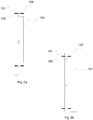
- a damping assembly in which L1 equals L2 is shown in Figs. 2a and 2b .
- the second perpendicular distance L2 is larger than the first perpendicular distance L1.
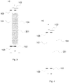
- the second volume is at least partly filled with flexible material structure 201.
- the flexible material structure 201 may be an insulating material, such as rock wool as depicted in Fig. 4 , insulating balls such as plastic insulating balls as depicted in Fig. 3 , glass wool, polystyrene balls, or any other insulating material.
- the flexible material structure 201 may also have sound damping properties, such as a sound damping material. Many insulating materials possess sound damping properties, whereby these kinds of materials are preferred.
- the flexible material structure is preferably porous, allowing for accommodating a volume of atmospheric gas.
- the second volume V2 may be at least partly incorporated as an atmospheric gas within the flexible material structure, and as an atmospheric gas partly exterior to the flexible material structure, in cases where the flexible material structure only partly fills the space between the first structure and second structure, such as in Fig. 10 .
- the space between the spherical insulating balls containing an atmospheric gas may form part of V2.
- the second volume created between the second and first structures may according to some embodiments advantageously be at least partly unobstructed by the flexible material structure, thereby providing at least one unobstructed passage between the second structure and the first structure. This improves the atmospheric gas movement within the second volume, which may allow for improved sound reduction.
- the flexible material structure contains a number of plastic insulating balls
- the flexibility of the flexible material structure should be adapted to allow for absorption of sound pressure waves. Accordingly, the flexible material structure does not pertain to a fully rigid structure, such as a plaster board, MDF or the like, through which the sound waves easily mechanically propagate, as this adversely affect the sound reduction capability. Also a rigid material would create additional direct mechanical contact points between the first structure and second structure. Instead, a flexible and shapeable material is preferred. Expressed in other terms it is preferred that the acoustic impedance of the flexible material structure is lower than both that of the first structure and second structure.
- the flexible material structure preferably has a lower density than that of the first structure 101 and second structure 104, 101.
- Fig. 5 illustrates a damping assembly 10 according to further embodiment, in which the second structure 104 is also resiliently attached to the studwork structure 102 by means of a number of resilient attachment members 103.
- the second structure may be identical to the first structure, thereby pertaining to an inner ceiling or wall.
- a difference in view of Fig. 1 is that the second structure is also resiliently attached to the studwork structure.
- an additional third volume V3 is created in this embodiment, as a third perpendicular distance L3 and a surface area of the at least one studwork structure 102 facing the second structure 104 form a third volume V3.
- the third volume V3 and the first volume V1 may be roughly equal.
- Total volume between the first structure and the second structure is formed by the second perpendicular distance L2 and a surface area of the second structure 104 facing the first structure 101.
- the total volume subtracted by the first volume V1, the third volume V3 and a volume of the studwork Vs forms the second volume in this embodiment.
- this additional volume may be taken into consideration when defining the second volume.
- This embodiment is advantageous for walls when sound proofing is desired from both sides of the wall, e.g. in open-plan office environments, and separating walls in apartments.
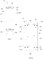
- Fig. 6a illustrates a damping assembly according to an embodiment, similar to that of Fig. 1 , in which a further studwork structure 102 and a further first structure 101 is arranged on the opposite side of the damping assembly of Fig. 1 .
- the further first structure is arranged at a third perpendicular distance L3 from the further studwork structure, and at a fourth perpendicular distance L4 from a surface of the second structure 104 facing the further first structure 101.
- both the second perpendicular distance L2 and the fourth perpendicular distance L4 is preferably greater than the first perpendicular distance L1 and the third perpendicular distance, respectively.
- the fourth perpendicular distance L4 and a surface area of the further first structure 101 facing the second structure 104 form a further total volume between the further first structure and the second structure.
- the total volume when subtracted by the third volume and a volume of the studwork Vs form a fourth volume V4.
- the further first structure may be denoted third structure for sake of clarity in the appended claims.
- the second volume V2 is larger than the first volume V1 and if available the fourth volume V4 is larger than the third volume V3.
- Fig. 6b illustrates a damping assembly according to an embodiment, wherein two inner ceiling or inner wall structures are connected on either side of a studwork structure, without any foundation structure 104 arranged between the two studwork structures 102.
- L2 is greater than L1 and L3, respectively, and that each of L1 and L3 is greater than zero in order to obtain the desired sound damping properties.
- the first L1 or third L3 perpendicular distance is in the range of 0,01 to 20 mm, e.g. 1 to 10, such as 1 to 5 mm, such 3 mm.
- the second L2 or fourth L4 perpendicular distance is in the range of 25 to 500mm, e.g. 50 to 300, such as 50 to 200mm.
- Fig. 7a illustrates an embodiment in which a further first structure or sheet of material 601 has been mounted on top of the first structure 101.
- the further sheet of material may e.g. be an additional plaster board, MDF, HDF or optionally glued onto the first structure 101.
- Fig. 7b illustrates a damping assembly, according to an embodiment, similar to that of Fig. 7a in which the further first structure is rigidly screwed to the first structure by means of conventional screws 701.
- the at least one resilient attachment member is attached to the at least one studwork structure straight through the first structure and the further first structure.
- this embodiment requires a slightly longer resilient attachment member than that required e.g. in view of Fig. 7a .
- the second structure 104, 101 may be rigidly attached to the studwork structure acting as a foundation of a wall, roof or floor of a building or accommodation, whereas the first structure 101 is resiliently suspended in relation to the second structure 104 via the resilient attachment member 103.
- An advantageous effect of the present invention is that it is possible to assemble the damping assembly in a one-directional manner, as the resilient attachment members may be screwed into the structures in essentially in the same way as commonly is performed when mounting plasterboards.
- the only difference is that an adapted mounting tool may be required, in case the resilient attachment member is not adapted to a particular standard.
- the present invention allows for a method of assembling the damping assembly as suggested by the incorporated embodiments.
- Such a method may pertain to a method for assembling a first structure 101 to a studwork structure 102 using at least one resilient attachment member 103.
- the method comprises the steps of simultaneously attaching a first portion 301 of the resilient attachment member 103 to the first structure 101 and a second portion 303 of the resilient attachment member 103 to the studwork structure 102.
- the resilient attachment member 102 is arranged straight through the first structure 101, thereby allowing for assembling the first structure 101 to the studwork structure 102 from one direction.
- the step of simultaneous attachment may be performed using a mounting tool connectable to the resilient attachment member 103 via a through bore provided therein.
- the mounting tool has a first member connectable to the first portion 301 of the resilient attachment member 103 and a second member connectable to the second portion 303 of the resilient attachment member 103, whereby upon rotation of the connected mounting tool the first portion 301 is screwed into the first structure 101 and the second portion 303 is screwed into the studwork structure 102.
- the first construction is resiliently attached to the studwork structure 102, while the second structure may be rigidly attached to the studwork structure opposite the first structure.
- the at least one resilient attachment member 103 is configured to resiliently attaching the at least one studwork structure 102 at a first perpendicular distance from the second structure 104, 101 such that the second structure 104, 101 and the at least one studwork structures 102 are in contact with each other only via the resilient attachment member(s) 103.
- the second structure 104, 101 is located at a second perpendicular distance from the first structure 101.
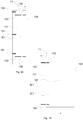
- the resilient attachment member may be provided between the studwork structure 102 and the second structure 104, whereby the first structure and optionally further first structure 601 may be rigidly attached to the studwork structure by means of conventional screws 701. It should be appreciated that the conventional screws 701 securing the further first structure to the first structure may be also attached to the studwork structure (see lower studwork structure).
- the resilient attachment member may be provided straight through the first structure and the studwork structure and then be rigidly attached to the second structure. This optionally requires a longer first portion 301 of the resilient attachment member.
- the damping assembly of Fig. 9a may optionally be used as an inner ceiling damping assembly for an sound proofing an existing ceiling, wherein the second structure is the floor foundation, such as an existing studwork structure of a property, whereas the studwork structure 102 is a further studwork structure, resiliently attached to the existing studwork structure 104, by means of the resilient attachment members.
- Fig. 10 illustrates a damping assembly according to an embodiment being provided with two inner ceiling or two inner wall structures with a resilient attachment member being provided straight through the inner wall or ceiling structures and anchored to the studwork construction.
Landscapes
- Engineering & Computer Science (AREA)
- Architecture (AREA)
- Physics & Mathematics (AREA)
- Civil Engineering (AREA)
- Structural Engineering (AREA)
- Electromagnetism (AREA)
- Acoustics & Sound (AREA)
- Thermal Sciences (AREA)
- Building Environments (AREA)
Claims (11)
- Dämpfungsanordnung (10) zum Reduzieren von Vibration, Schall oder Geräuschausbreitung zwischen mindestens zwei Strukturen, umfassendeine erste Struktur (101), wie zum Beispiel eine innere Deckenkonstruktion,mindestens eine Ständerwerkstruktur (102),mindestens ein elastisches Befestigungselement (103) zum elastischen Befestigen der ersten Struktur (101) in einem ersten senkrechten Abstand (L1) zu der mindestens einen Ständerwerkstruktur (102), derart, dass die erste Struktur (101) und die mindestens eine Ständerwerkstruktur (102) nur über das/die elastische(n) Befestigungselement(e) (103) miteinander in Kontakt sind, wobei das elastische Befestigungselement (103) Folgendes umfasst:einen ersten Abschnitt (301), der mit einem Außengewinde zur starren Verbindung mit der ersten Struktur (101) versehen ist,einen elastischen Zwischenabschnitt (302), der den ersten Abschnitt (301) mit einem zweiten Abschnitt (303) verbindet, der mit einem weiteren Außengewinde zur starren Verbindung mit der Ständerwerkstruktur (102) versehen ist, wobei die Abmessung des weiteren Außengewindes kleiner ist als das Außengewinde des ersten Abschnitts (301), wobei der elastische Zwischenabschnitt (302) dazu dient, den ersten Abschnitt (301) und den zweiten Abschnitt (303) in einem entspannten oder untätigen Zustand in einem Abstand voneinander zu halten,wobei der erste Abschnitt (301) mit einer ersten Passeinheit versehen ist und der zweite Abschnitt (303) mit einer zweiten Passeinheit versehen ist, wobei die erste Passeinheit angeordnet ist, um die zweite Passeinheit in einem komprimierten Zustand des elastischen Befestigungselementes (103) derart aufzunehmen, dass, wenn die beiden passeinheiten verbunden sind, jede relative Drehung zwischen dem ersten Abschnitt (301) und dem zweiten Abschnitt (303) verhindert wird, wodurch ermöglicht wird, dass der erste Abschnitt (301) in die erste Struktur (101) und der zweite Abschnitt (303) gleichzeitig in die Ständerwerkstruktur (102) eingeschraubt wird,wobei der zweite Abschnitt (303) des mindestens einen elastischen Befestigungselements an der mindestens einen Ständerwerksstruktur (102) über ein Loch in der ersten Struktur (101) befestigt ist, ohne die erste Struktur (101), aufgrund der geringeren Abmessung des Außengewindes des zweiten Abschnitts (303), während der Montage zu stören,wobei die mindestens eine Ständerwerkstruktur (102) mit einer zweiten Struktur (104, 101) verbunden ist, die der ersten Struktur (101) gegenüberliegend angeordnet ist, wobei die zweite Struktur (104, 101) in einem zweiten senkrechten Abstand (L2) von der ersten Struktur (101) angeordnet ist,wobei das elastische Element auch einen ausgefahrenen Zustand hat, in dem der erste Abschnitt (301) und der zweite Abschnitt (303) in einem maximalen Längsabstand voneinander entfernt positioniert sind, wobei der zweite senkrechte Abstand (L2) im ausgefahrenen Zustand größer ist als im komprimierten Zustand, wobei sich das elastische Befestigungselement (103) in einem Zustand zwischen dem ausgefahrenen Zustand und dem komprimierten Zustand befindet, wenn sich der elastische Zwischenabschnitt (302) in seinem untätigen zustand befindet.wobei der erste senkrechte Abstand (L1) und ein Oberflächenbereich der mindestens einen Ständerwerkstruktur (102), der der ersten Struktur (101) zugewandt ist, ein erstes Volumen (V1) bilden,wobei der zweite senkrechte Abstand (L2) und ein Oberflächenbereich der zweiten Struktur (104, 101), der der ersten Struktur (101) zugewandt ist, ein Gesamtvolumen zwischen der ersten Struktur (101) und der zweiten Struktur (104, 101) bilden, wobei das Gesamtvolumen, wenn mit dem ersten Volumen (V1) und einem Volumen der Ständerwerkstruktur (Vs) subtrahiert wird, ein zweites Volumen (V2) bildet, undwobei das zweite Volumen (V2) größer ist als das erste Volumen (V1), und wobei der zweite senkrechte Abstand (L2) größer als der erste senkrechte Abstand (L1) ist.
- Dämpfungsanordnung nach Anspruch 1, wobei der erste senkrechte Abstand (L1) größer als null ist.
- Dämpfungsanordnung (10) nach einem der vorhergehenden Ansprüche, wobei das zweite Volumen zumindest teilweise mit einer flexiblen Materialstruktur (201) gefüllt ist.
- Dämpfungsanordnung (10) nach Anspruch 3, wobei die flexible Materialstruktur (201) ein isolierendes Material ist.
- Dämpfungsanordnung (10) nach Anspruch 3, wobei die flexible Materialstruktur (201) ein schalldämpfendes Material ist.
- Dämpfungsanordnung (10) nach Anspruch 3, wobei es mindestens einen ungehinderten Durchgang zwischen der zweiten Struktur und der ersten Struktur gibt.
- Dämpfungsanordnung (10) nach einem der vorhergehenden Ansprüche,wobei der zweite senkrechte Abstand im komprimierten Zustand größer als Null ist und wobei der zweite senkrechte Abstand zwischen der ersten Struktur (101) und der zweiten Struktur (104, 101) im ausgefahrenen Zustand größer ist als der im komprimierten Zustand.wodurch eine Bewegung der ersten Struktur (101) in Bezug auf die zweite Struktur (104, 101) ermöglicht wird.
- Dämpfungsanordnung (10) nach einem der vorhergehenden Ansprüche, wobei ein kürzester Abstand zwischen der ersten Struktur (101) und der zweiten Struktur (104, 101) größer als null ist.
- Dämpfungsanordnung (10) nach einem der vorhergehenden Ansprüche, wobeidie zweite Struktur (104, 101) starr an einem Fundament einer Wand, eines Daches oder eines Bodens eines Gebäudes oder einer Unterkunft befestigt ist, und wobeidie erste Struktur (101) in Bezug auf die zweite Struktur (200) über das elastische Befestigungselement (103) aufgehängt ist.
- Dämpfungsanordnung nach einem der vorhergehenden Ansprüche, umfassend eine dritte Struktur, die durch mindestens ein weiteres elastisches Befestigungselement (103) über mindestens eine weitere Ständerstruktur (102) elastisch an der zweiten Struktur (104, 101) befestigt ist.
- Verfahren zum Anbringen einer ersten Struktur (101) an einer Ständerwerkstruktur (102) unter Verwendung eines elastischen Befestigungselements (103), wobei das Verfahren eine Anordnung nach Anspruch 1 verwendet, indem gleichzeitig ein erster Abschnitt (301) des elastischen Befestigungselements (103) an der ersten Struktur (101) und ein zweiter Abschnitt (303) des elastischen Befestigungselements (103) an der Ständerwerkstruktur (102) befestigt wird, beim Einführen des zweiten Abschnitts (303) durch das Loch in der ersten Struktur in Richtung der Ständerwerksstruktur (102), gefolgt vom Zusammendrücken des elastischen Zwischenabschnitts (302) in seinen komprimierten Zustand, wodurch die erste Passeinheit und die zweite Passeinheit zusammenpassen und eine relative Drehung zwischen dem ersten Abschnitt (301) und dem zweiten Abschnitt (303) verhindert wird, um das Einschrauben des ersten Abschnitts (301) in die erste Struktur (101) und das gleichzeitige Einschrauben des zweiten Abschnitts (303) in die Ständerwerkstruktur (102) ermöglichen, wodurch das elastische Befestigungselement (102) gerade durch die erste Struktur (101) angeordnet wird, wodurch die Montage der ersten Struktur (101) an der Ständerwerkstruktur (102) aus einer Richtung ermöglicht wird.
Applications Claiming Priority (2)
| Application Number | Priority Date | Filing Date | Title |
|---|---|---|---|
| SE1251329A SE542814C2 (sv) | 2012-11-23 | 2012-11-23 | Dämpningsanordning för att minska utbredning av vibrationer, ljud eller buller samt metod för montering med hjälp av dämpningsanordningen |
| PCT/EP2013/074656 WO2014080022A1 (en) | 2012-11-23 | 2013-11-25 | Dampening assembly |
Publications (2)
| Publication Number | Publication Date |
|---|---|
| EP2923005A1 EP2923005A1 (de) | 2015-09-30 |
| EP2923005B1 true EP2923005B1 (de) | 2021-11-10 |
Family
ID=49679511
Family Applications (1)
| Application Number | Title | Priority Date | Filing Date |
|---|---|---|---|
| EP13798303.7A Not-in-force EP2923005B1 (de) | 2012-11-23 | 2013-11-25 | Dämpfungsanordnung |
Country Status (7)
| Country | Link |
|---|---|
| US (1) | US20150275511A1 (de) |
| EP (1) | EP2923005B1 (de) |
| CN (1) | CN105102736A (de) |
| AU (1) | AU2013349613A1 (de) |
| CA (1) | CA2892201A1 (de) |
| SE (1) | SE542814C2 (de) |
| WO (1) | WO2014080022A1 (de) |
Families Citing this family (6)
| Publication number | Priority date | Publication date | Assignee | Title |
|---|---|---|---|---|
| ES2609601B1 (es) * | 2016-09-02 | 2018-01-24 | Dario Alejandro CAFFARATTI GIRO | Sistema constructivo con propiedades de aislamiento acustico |
| LT6519B (lt) | 2016-09-23 | 2018-04-25 | Kraponas Povilas | Tarpbutinės pertvaros garso izoliacinis sluoksnis ir tarpbutinė pertvara |
| LT6520B (lt) | 2016-09-23 | 2018-04-25 | Uab "Mg United" | Tarpbutinės pertvaros garso izoliacinis sluoksnis ir tarpbutinė pertvara |
| GB2577328A (en) * | 2018-09-24 | 2020-03-25 | Saint Gobain Construction Products Uk Ltd | Partitions comprising boards mounted onto upright elongate members and methods for constructing the same |
| SE544883C2 (en) | 2020-11-20 | 2022-12-20 | Akoustos Ab | Resilient fastening arrangement, use thereof and vibration damping assembly |
| US12258755B2 (en) * | 2021-08-20 | 2025-03-25 | Mtec, Llc | Sound isolation assemblies for walls supporting heavy loads |
Family Cites Families (16)
| Publication number | Priority date | Publication date | Assignee | Title |
|---|---|---|---|---|
| US1940933A (en) * | 1932-02-23 | 1933-12-26 | United States Gypsum Co | Wall and ceiling construction |
| US2853746A (en) * | 1953-11-30 | 1958-09-30 | Ultra Tach Co | Insulation mounting |
| US3046620A (en) * | 1956-03-20 | 1962-07-31 | Stephen W Tvorik | Ceiling hanger |
| US3305993A (en) * | 1964-06-10 | 1967-02-28 | United States Gypsum Co | Sound control wall construction |
| US3391508A (en) * | 1965-12-02 | 1968-07-09 | Flintkote Co | Resilient furring strip for gypsum board wall system |
| US3445975A (en) * | 1966-03-18 | 1969-05-27 | United States Gypsum Co | Sound control partition with resilient support studs |
| US3477187A (en) * | 1968-01-19 | 1969-11-11 | Albert A Fruman | Wallboard mounting channel |
| US4227360A (en) * | 1977-05-05 | 1980-10-14 | United States Gypsum Company | Resilient furring member |
| US4394808A (en) * | 1980-11-25 | 1983-07-26 | Robert S. Agar, Inc. | Fastener for attaching panel to stud |
| US6266936B1 (en) * | 1999-06-24 | 2001-07-31 | Johns Manville International, Inc. | Sound attenuating and thermal insulating wall and ceiling assembly |
| CA2391775A1 (en) * | 1999-08-31 | 2001-03-08 | Owens Corning | System for retrofitting a wall to increase sound attenuation |
| DE60126633T2 (de) * | 2000-10-13 | 2007-11-22 | Martinson Group Ab | Vorgefertigtes deckenstrukturelement und verfahren zur herstellung solcher elemente |
| US6668504B2 (en) * | 2002-04-11 | 2003-12-30 | Knight-Celotex, L.L.C. | Sound-deadened wall and wall panel for same |
| SE532372C2 (sv) * | 2007-03-21 | 2009-12-29 | Lars Haakan Wernersson | Fjädrande infästande arrangemang |
| EP2313570A4 (de) * | 2008-05-15 | 2014-12-31 | Saint Gobain Performance Plast | Wand- und deckenschalldämpfungshalterung und -kanäle |
| CN202031204U (zh) * | 2011-01-24 | 2011-11-09 | 中国建筑材料科学研究总院 | 一种高隔声量的轻质复合墙体 |
-
2012
- 2012-11-23 SE SE1251329A patent/SE542814C2/sv not_active IP Right Cessation
-
2013
- 2013-11-25 US US14/646,863 patent/US20150275511A1/en not_active Abandoned
- 2013-11-25 CA CA2892201A patent/CA2892201A1/en not_active Abandoned
- 2013-11-25 CN CN201380071235.3A patent/CN105102736A/zh active Pending
- 2013-11-25 EP EP13798303.7A patent/EP2923005B1/de not_active Not-in-force
- 2013-11-25 WO PCT/EP2013/074656 patent/WO2014080022A1/en not_active Ceased
- 2013-11-25 AU AU2013349613A patent/AU2013349613A1/en not_active Abandoned
Non-Patent Citations (1)
| Title |
|---|
| None * |
Also Published As
| Publication number | Publication date |
|---|---|
| EP2923005A1 (de) | 2015-09-30 |
| AU2013349613A1 (en) | 2015-07-09 |
| WO2014080022A1 (en) | 2014-05-30 |
| CN105102736A (zh) | 2015-11-25 |
| SE542814C2 (sv) | 2020-07-14 |
| US20150275511A1 (en) | 2015-10-01 |
| SE1251329A1 (sv) | 2014-05-24 |
| CA2892201A1 (en) | 2014-05-30 |
Similar Documents
| Publication | Publication Date | Title |
|---|---|---|
| US20150275511A1 (en) | Dampening assembly | |
| US6758305B2 (en) | Combination sound-deadening board | |
| US6715241B2 (en) | Lightweight sound-deadening board | |
| EP3478897A1 (de) | Trockenwandbausystem mit federschiene | |
| JP6456594B2 (ja) | 内装壁の取付構造及び取付方法 | |
| EP0965701A1 (de) | Schallisolierende Platte | |
| JP3182369B2 (ja) | 建築物の防振構造 | |
| KR20200076322A (ko) | 층간소음 저감을 위한 방진패널 및 이를 이용하여 방진구조를 시공하는 방법 | |
| KR200397319Y1 (ko) | 실내 칸막이용 판넬구조 | |
| EP4248097B1 (de) | Elastische befestigungsanordnung, schwingungsdämpfende anordnung und verfahren zum bau einer schwingungsdämpfenden anordnung | |
| US20250027315A1 (en) | Component for producing building parts such as walls and ceilings | |
| JP2011144586A (ja) | 室の防音構造 | |
| JP3365277B2 (ja) | 床構造 | |
| KR100585459B1 (ko) | 칸막이 벽체 구조물 | |
| CN212715583U (zh) | 一种eps石墨浮筑楼板保温隔音板 | |
| CN218522013U (zh) | 一种龙骨降噪隔音墙 | |
| JPH0813640A (ja) | 防音パネル | |
| JP2002227393A (ja) | 二重床 | |
| JP5395390B2 (ja) | ユニット建物及び建物ユニット | |
| CN214941904U (zh) | 一种拼装式隔音装饰墙 | |
| JP2022148459A (ja) | 床材パネル、床材パネル群、床材ユニット及び防音ブース | |
| KR100520719B1 (ko) | 건축용 단열 보드 일체형 내부 마감재 | |
| KR101774413B1 (ko) | 고차음 스터드 구조체 | |
| KR200405617Y1 (ko) | 아파트 등 공동주택의 층간차음재 | |
| CN119553807A (zh) | 一种隔音防火集成装配式隔墙龙骨 |
Legal Events
| Date | Code | Title | Description |
|---|---|---|---|
| PUAI | Public reference made under article 153(3) epc to a published international application that has entered the european phase |
Free format text: ORIGINAL CODE: 0009012 |
|
| 17P | Request for examination filed |
Effective date: 20150622 |
|
| AK | Designated contracting states |
Kind code of ref document: A1 Designated state(s): AL AT BE BG CH CY CZ DE DK EE ES FI FR GB GR HR HU IE IS IT LI LT LU LV MC MK MT NL NO PL PT RO RS SE SI SK SM TR |
|
| AX | Request for extension of the european patent |
Extension state: BA ME |
|
| DAX | Request for extension of the european patent (deleted) | ||
| 17Q | First examination report despatched |
Effective date: 20160512 |
|
| STAA | Information on the status of an ep patent application or granted ep patent |
Free format text: STATUS: EXAMINATION IS IN PROGRESS |
|
| GRAP | Despatch of communication of intention to grant a patent |
Free format text: ORIGINAL CODE: EPIDOSNIGR1 |
|
| STAA | Information on the status of an ep patent application or granted ep patent |
Free format text: STATUS: GRANT OF PATENT IS INTENDED |
|
| INTG | Intention to grant announced |
Effective date: 20210615 |
|
| GRAS | Grant fee paid |
Free format text: ORIGINAL CODE: EPIDOSNIGR3 |
|
| GRAA | (expected) grant |
Free format text: ORIGINAL CODE: 0009210 |
|
| STAA | Information on the status of an ep patent application or granted ep patent |
Free format text: STATUS: THE PATENT HAS BEEN GRANTED |
|
| AK | Designated contracting states |
Kind code of ref document: B1 Designated state(s): AL AT BE BG CH CY CZ DE DK EE ES FI FR GB GR HR HU IE IS IT LI LT LU LV MC MK MT NL NO PL PT RO RS SE SI SK SM TR |
|
| REG | Reference to a national code |
Ref country code: GB Ref legal event code: FG4D |
|
| REG | Reference to a national code |
Ref country code: AT Ref legal event code: REF Ref document number: 1446232 Country of ref document: AT Kind code of ref document: T Effective date: 20211115 Ref country code: CH Ref legal event code: EP |
|
| REG | Reference to a national code |
Ref country code: DE Ref legal event code: R096 Ref document number: 602013079990 Country of ref document: DE |
|
| REG | Reference to a national code |
Ref country code: IE Ref legal event code: FG4D |
|
| REG | Reference to a national code |
Ref country code: NL Ref legal event code: FP |
|
| REG | Reference to a national code |
Ref country code: LT Ref legal event code: MG9D |
|
| REG | Reference to a national code |
Ref country code: AT Ref legal event code: MK05 Ref document number: 1446232 Country of ref document: AT Kind code of ref document: T Effective date: 20211110 |
|
| PG25 | Lapsed in a contracting state [announced via postgrant information from national office to epo] |
Ref country code: RS Free format text: LAPSE BECAUSE OF FAILURE TO SUBMIT A TRANSLATION OF THE DESCRIPTION OR TO PAY THE FEE WITHIN THE PRESCRIBED TIME-LIMIT Effective date: 20211110 Ref country code: LT Free format text: LAPSE BECAUSE OF FAILURE TO SUBMIT A TRANSLATION OF THE DESCRIPTION OR TO PAY THE FEE WITHIN THE PRESCRIBED TIME-LIMIT Effective date: 20211110 Ref country code: FI Free format text: LAPSE BECAUSE OF FAILURE TO SUBMIT A TRANSLATION OF THE DESCRIPTION OR TO PAY THE FEE WITHIN THE PRESCRIBED TIME-LIMIT Effective date: 20211110 Ref country code: BG Free format text: LAPSE BECAUSE OF FAILURE TO SUBMIT A TRANSLATION OF THE DESCRIPTION OR TO PAY THE FEE WITHIN THE PRESCRIBED TIME-LIMIT Effective date: 20220210 Ref country code: AT Free format text: LAPSE BECAUSE OF FAILURE TO SUBMIT A TRANSLATION OF THE DESCRIPTION OR TO PAY THE FEE WITHIN THE PRESCRIBED TIME-LIMIT Effective date: 20211110 |
|
| PG25 | Lapsed in a contracting state [announced via postgrant information from national office to epo] |
Ref country code: IS Free format text: LAPSE BECAUSE OF FAILURE TO SUBMIT A TRANSLATION OF THE DESCRIPTION OR TO PAY THE FEE WITHIN THE PRESCRIBED TIME-LIMIT Effective date: 20220310 Ref country code: SE Free format text: LAPSE BECAUSE OF FAILURE TO SUBMIT A TRANSLATION OF THE DESCRIPTION OR TO PAY THE FEE WITHIN THE PRESCRIBED TIME-LIMIT Effective date: 20211110 Ref country code: PT Free format text: LAPSE BECAUSE OF FAILURE TO SUBMIT A TRANSLATION OF THE DESCRIPTION OR TO PAY THE FEE WITHIN THE PRESCRIBED TIME-LIMIT Effective date: 20220310 Ref country code: PL Free format text: LAPSE BECAUSE OF FAILURE TO SUBMIT A TRANSLATION OF THE DESCRIPTION OR TO PAY THE FEE WITHIN THE PRESCRIBED TIME-LIMIT Effective date: 20211110 Ref country code: NO Free format text: LAPSE BECAUSE OF FAILURE TO SUBMIT A TRANSLATION OF THE DESCRIPTION OR TO PAY THE FEE WITHIN THE PRESCRIBED TIME-LIMIT Effective date: 20220210 Ref country code: LV Free format text: LAPSE BECAUSE OF FAILURE TO SUBMIT A TRANSLATION OF THE DESCRIPTION OR TO PAY THE FEE WITHIN THE PRESCRIBED TIME-LIMIT Effective date: 20211110 Ref country code: HR Free format text: LAPSE BECAUSE OF FAILURE TO SUBMIT A TRANSLATION OF THE DESCRIPTION OR TO PAY THE FEE WITHIN THE PRESCRIBED TIME-LIMIT Effective date: 20211110 Ref country code: GR Free format text: LAPSE BECAUSE OF FAILURE TO SUBMIT A TRANSLATION OF THE DESCRIPTION OR TO PAY THE FEE WITHIN THE PRESCRIBED TIME-LIMIT Effective date: 20220211 Ref country code: ES Free format text: LAPSE BECAUSE OF FAILURE TO SUBMIT A TRANSLATION OF THE DESCRIPTION OR TO PAY THE FEE WITHIN THE PRESCRIBED TIME-LIMIT Effective date: 20211110 |
|
| REG | Reference to a national code |
Ref country code: DE Ref legal event code: R119 Ref document number: 602013079990 Country of ref document: DE |
|
| REG | Reference to a national code |
Ref country code: CH Ref legal event code: PL |
|
| PG25 | Lapsed in a contracting state [announced via postgrant information from national office to epo] |
Ref country code: SM Free format text: LAPSE BECAUSE OF FAILURE TO SUBMIT A TRANSLATION OF THE DESCRIPTION OR TO PAY THE FEE WITHIN THE PRESCRIBED TIME-LIMIT Effective date: 20211110 Ref country code: SK Free format text: LAPSE BECAUSE OF FAILURE TO SUBMIT A TRANSLATION OF THE DESCRIPTION OR TO PAY THE FEE WITHIN THE PRESCRIBED TIME-LIMIT Effective date: 20211110 Ref country code: RO Free format text: LAPSE BECAUSE OF FAILURE TO SUBMIT A TRANSLATION OF THE DESCRIPTION OR TO PAY THE FEE WITHIN THE PRESCRIBED TIME-LIMIT Effective date: 20211110 Ref country code: LU Free format text: LAPSE BECAUSE OF NON-PAYMENT OF DUE FEES Effective date: 20211125 Ref country code: EE Free format text: LAPSE BECAUSE OF FAILURE TO SUBMIT A TRANSLATION OF THE DESCRIPTION OR TO PAY THE FEE WITHIN THE PRESCRIBED TIME-LIMIT Effective date: 20211110 Ref country code: DK Free format text: LAPSE BECAUSE OF FAILURE TO SUBMIT A TRANSLATION OF THE DESCRIPTION OR TO PAY THE FEE WITHIN THE PRESCRIBED TIME-LIMIT Effective date: 20211110 Ref country code: CZ Free format text: LAPSE BECAUSE OF FAILURE TO SUBMIT A TRANSLATION OF THE DESCRIPTION OR TO PAY THE FEE WITHIN THE PRESCRIBED TIME-LIMIT Effective date: 20211110 Ref country code: BE Free format text: LAPSE BECAUSE OF NON-PAYMENT OF DUE FEES Effective date: 20211130 |
|
| REG | Reference to a national code |
Ref country code: BE Ref legal event code: MM Effective date: 20211130 |
|
| PG25 | Lapsed in a contracting state [announced via postgrant information from national office to epo] |
Ref country code: MC Free format text: LAPSE BECAUSE OF FAILURE TO SUBMIT A TRANSLATION OF THE DESCRIPTION OR TO PAY THE FEE WITHIN THE PRESCRIBED TIME-LIMIT Effective date: 20211110 |
|
| PLBE | No opposition filed within time limit |
Free format text: ORIGINAL CODE: 0009261 |
|
| STAA | Information on the status of an ep patent application or granted ep patent |
Free format text: STATUS: NO OPPOSITION FILED WITHIN TIME LIMIT |
|
| 26N | No opposition filed |
Effective date: 20220811 |
|
| PG25 | Lapsed in a contracting state [announced via postgrant information from national office to epo] |
Ref country code: DE Free format text: LAPSE BECAUSE OF NON-PAYMENT OF DUE FEES Effective date: 20220601 Ref country code: AL Free format text: LAPSE BECAUSE OF FAILURE TO SUBMIT A TRANSLATION OF THE DESCRIPTION OR TO PAY THE FEE WITHIN THE PRESCRIBED TIME-LIMIT Effective date: 20211110 |
|
| PG25 | Lapsed in a contracting state [announced via postgrant information from national office to epo] |
Ref country code: SI Free format text: LAPSE BECAUSE OF FAILURE TO SUBMIT A TRANSLATION OF THE DESCRIPTION OR TO PAY THE FEE WITHIN THE PRESCRIBED TIME-LIMIT Effective date: 20211110 Ref country code: FR Free format text: LAPSE BECAUSE OF NON-PAYMENT OF DUE FEES Effective date: 20220110 |
|
| PGFP | Annual fee paid to national office [announced via postgrant information from national office to epo] |
Ref country code: NL Payment date: 20221109 Year of fee payment: 10 Ref country code: IE Payment date: 20221117 Year of fee payment: 10 Ref country code: GB Payment date: 20221117 Year of fee payment: 10 |
|
| PG25 | Lapsed in a contracting state [announced via postgrant information from national office to epo] |
Ref country code: IT Free format text: LAPSE BECAUSE OF FAILURE TO SUBMIT A TRANSLATION OF THE DESCRIPTION OR TO PAY THE FEE WITHIN THE PRESCRIBED TIME-LIMIT Effective date: 20211110 Ref country code: HU Free format text: LAPSE BECAUSE OF FAILURE TO SUBMIT A TRANSLATION OF THE DESCRIPTION OR TO PAY THE FEE WITHIN THE PRESCRIBED TIME-LIMIT; INVALID AB INITIO Effective date: 20131125 |
|
| PG25 | Lapsed in a contracting state [announced via postgrant information from national office to epo] |
Ref country code: CY Free format text: LAPSE BECAUSE OF FAILURE TO SUBMIT A TRANSLATION OF THE DESCRIPTION OR TO PAY THE FEE WITHIN THE PRESCRIBED TIME-LIMIT Effective date: 20211110 |
|
| PG25 | Lapsed in a contracting state [announced via postgrant information from national office to epo] |
Ref country code: LI Free format text: LAPSE BECAUSE OF NON-PAYMENT OF DUE FEES Effective date: 20220630 Ref country code: CH Free format text: LAPSE BECAUSE OF NON-PAYMENT OF DUE FEES Effective date: 20220630 |
|
| PG25 | Lapsed in a contracting state [announced via postgrant information from national office to epo] |
Ref country code: MK Free format text: LAPSE BECAUSE OF FAILURE TO SUBMIT A TRANSLATION OF THE DESCRIPTION OR TO PAY THE FEE WITHIN THE PRESCRIBED TIME-LIMIT Effective date: 20211110 |
|
| PG25 | Lapsed in a contracting state [announced via postgrant information from national office to epo] |
Ref country code: TR Free format text: LAPSE BECAUSE OF FAILURE TO SUBMIT A TRANSLATION OF THE DESCRIPTION OR TO PAY THE FEE WITHIN THE PRESCRIBED TIME-LIMIT Effective date: 20211110 |
|
| REG | Reference to a national code |
Ref country code: NL Ref legal event code: MM Effective date: 20231201 |
|
| GBPC | Gb: european patent ceased through non-payment of renewal fee |
Effective date: 20231125 |
|
| PG25 | Lapsed in a contracting state [announced via postgrant information from national office to epo] |
Ref country code: NL Free format text: LAPSE BECAUSE OF NON-PAYMENT OF DUE FEES Effective date: 20231201 |
|
| REG | Reference to a national code |
Ref country code: IE Ref legal event code: MM4A |
|
| PG25 | Lapsed in a contracting state [announced via postgrant information from national office to epo] |
Ref country code: NL Free format text: LAPSE BECAUSE OF NON-PAYMENT OF DUE FEES Effective date: 20231201 Ref country code: MT Free format text: LAPSE BECAUSE OF FAILURE TO SUBMIT A TRANSLATION OF THE DESCRIPTION OR TO PAY THE FEE WITHIN THE PRESCRIBED TIME-LIMIT Effective date: 20211110 |
|
| PG25 | Lapsed in a contracting state [announced via postgrant information from national office to epo] |
Ref country code: IE Free format text: LAPSE BECAUSE OF NON-PAYMENT OF DUE FEES Effective date: 20231125 |
|
| PG25 | Lapsed in a contracting state [announced via postgrant information from national office to epo] |
Ref country code: GB Free format text: LAPSE BECAUSE OF NON-PAYMENT OF DUE FEES Effective date: 20231125 |
|
| PG25 | Lapsed in a contracting state [announced via postgrant information from national office to epo] |
Ref country code: IE Free format text: LAPSE BECAUSE OF NON-PAYMENT OF DUE FEES Effective date: 20231125 Ref country code: GB Free format text: LAPSE BECAUSE OF NON-PAYMENT OF DUE FEES Effective date: 20231125 |