EP2921597A1 - Betätigungsvorrichtung - Google Patents
Betätigungsvorrichtung Download PDFInfo
- Publication number
- EP2921597A1 EP2921597A1 EP14161161.6A EP14161161A EP2921597A1 EP 2921597 A1 EP2921597 A1 EP 2921597A1 EP 14161161 A EP14161161 A EP 14161161A EP 2921597 A1 EP2921597 A1 EP 2921597A1
- Authority
- EP
- European Patent Office
- Prior art keywords
- actuating device
- receptacle
- optical waveguide
- frame
- light
- Prior art date
- Legal status (The legal status is an assumption and is not a legal conclusion. Google has not performed a legal analysis and makes no representation as to the accuracy of the status listed.)
- Granted
Links
Images


Classifications
-
- E—FIXED CONSTRUCTIONS
- E03—WATER SUPPLY; SEWERAGE
- E03D—WATER-CLOSETS OR URINALS WITH FLUSHING DEVICES; FLUSHING VALVES THEREFOR
- E03D5/00—Special constructions of flushing devices, e.g. closed flushing system
- E03D5/10—Special constructions of flushing devices, e.g. closed flushing system operated electrically, e.g. by a photo-cell; also combined with devices for opening or closing shutters in the bowl outlet and/or with devices for raising/or lowering seat and cover and/or for swiveling the bowl
- E03D5/105—Special constructions of flushing devices, e.g. closed flushing system operated electrically, e.g. by a photo-cell; also combined with devices for opening or closing shutters in the bowl outlet and/or with devices for raising/or lowering seat and cover and/or for swiveling the bowl touchless, e.g. using sensors
Definitions
- the present invention relates to an actuating device for triggering a flushing on a toilet or a urinal with lighting elements according to the preamble of claim 1.
- an actuator which has at least one display element.
- the display elements comprise a light source, which can be perceived by the user on the front side of the plate.
- the lighting means essentially serves to signal the position of the sensors which the user is to actuate for the flushing release.
- the bulbs allow the user to identify in which areas of the plate the hand must be placed so that the flush is triggered.
- the lamps radiate into the room they are formed in practice so that they have a brightness that does not really illuminate the room.
- the choice of greater brightness would also dazzle the user, for example at night, precisely because such panels are typically mounted slightly below eye level. Consequently, it comes from the technical teaching of EP 2 578 758 the disadvantage that the bulbs can not be used as a night light.
- the invention has for its object to provide an actuating device which overcomes the disadvantages of the prior art and in particular can be used as a night light.
- an actuating device for actuating a flushing device of a toilet or a urinal a frame element with a frame wall, which frame wall inside by an inner surface, on the outside by an outer surface, the front by a front end face and back by a rear end surface is delimited, which inner surface delimits a frame opening, a front of the, in particular in contact with the front end face extending at least over the frame opening extending plate, at least one arranged behind the plate lamp and at least one detection element to provide a signal for the flushing.
- the frame element comprises at least one receptacle for the luminous means, wherein the receptacle penetrates the outer surface of the frame element with at least one or exactly one aperture, so that light from the luminous element can be emitted laterally to the frame element through said aperture in the outer surface.
- a gleam of light can be provided, which in the installation position can be emitted laterally from the actuating device.
- the user is not dazzled by the light, but can still be well oriented in the room.
- the luminous means comprises at least one light source, in particular a light-emitting diode, which provides the light via the aperture.
- the luminous means comprises at least one light source, in particular a light emitting diode, and at least one optical waveguide with at least one coupling surface and at least one outcoupling surface, wherein the light source, the light via the coupling surface in the Coupled optical waveguide and decoupled via the decoupling surface of the optical waveguide.
- the decoupling surface preferably extends completely over the opening in the outer surface.
- the actuator is installed in the installed state such that the coupling surface in front of the wall, on or in which the actuator is installed, is located.
- the light source or the light source and the optical waveguide are arranged in said receptacle and thus mounted directly on the frame member.
- At least two light sources are arranged per optical waveguide, which couple in the light via at least two different coupling surfaces.
- the light source in the form of a light-emitting diode is preferably an RGB light-emitting diode with which the light can be provided in different colors.
- At least two or exactly two optical waveguides are arranged per outer surface of the frame element.
- the optical waveguides are preferably designed to have different lengths. As a result, not only can a night light be provided, but the user can also be signaled the position of a first detection element for the partial flush and the position of a second detection element for the full flush.
- the shorter formed optical waveguide is assigned to the first detection element for the partial flushing and the longer formed optical waveguide is associated with the second detection element for the Vollmengen Nursingung. In other words, the optical waveguide is divided on an outer surface.
- the two optical waveguides can be of equal length to each other.
- these are preferably arranged on a common outer surface.
- a single optical waveguide with at least one light source is arranged per outer surface of the frame element.
- the decoupling surface of the optical waveguide is flush with the outer surface. Consequently, the decoupling surface forms over the breakthrough part of the outer surface.
- the breakthrough is closed with a transparent or translucent window, which window is flush with the outer surface. The light can then be emitted by the light source via the window.
- the aperture extends exclusively over a portion of the outer surface.
- the opening is formed directly and immediately adjacent to the front or the rear end face of the frame element.
- the breakthrough may also be enclosed by the outer surface.
- the receptacle extends from the front end face into the frame wall and has a bottom, which is spaced from the front end face and rear end face.
- the receptacle further comprises at least one stop shoulder and opposite the stop shoulder on a rear wall, wherein the stop shoulder and the rear wall provide a stop for the light source, in particular for the optical waveguide.
- the receptacle can also have at least one side wall laterally, which adjoins the rear wall and connects it to the stop shoulder.
- the plate is positively and / or cohesively with the frame member connected and provides a stop for the bulb ready.
- the light source is in direct contact with the plate with the side facing the plate. The distance between the bottom of the receptacle and the plate substantially corresponds to the thickness of the optical waveguide, so that it is clamped between the bottom and the plate.
- the plate protrudes laterally beyond the frame element, in particular over the outer surface.
- the plate therefore has a greater extent than the frame element when viewed in the direction of the surface normal to the plate.
- the illuminant is held positively and / or cohesively in the receptacle.
- the receptacle advantageously has the shape described above.
- the light source is preferably connected via an adhesive connection with the receptacle.
- the optical waveguide is held in a form-fitting manner, while the light-emitting diode is firmly bonded in the receptacle.
- the frame element in the direction of the surface normal to the plate considered a rectangle or a square, wherein in each case a receptacle are arranged on two opposite sides of the rectangle or of the square, or wherein the receptacle is arranged on only one side of the rectangle or the square, or wherein in each case a receptacle is arranged on two opposite sides of the rectangle or of the square and is arranged on at least one further side of the rectangle or of the square, or wherein in each case a receptacle is arranged on all four sides of the rectangle or of the square.
- the luminous means in particular the optical waveguide or the two optical waveguides, extends essentially over the entire length of the corresponding side or outer surface.
- the luminous means in particular the optical waveguide or the two optical waveguides, extends essentially over a length of at least 60% or at least 80% of the length of the corresponding side.
- the detection element is a sensor arranged behind the plate.
- two detection elements one for the initiation of a full-flush and one for the initiation of a sectionmengen Introduceung, arranged.
- the sensing element is a button mounted in the plate and movable relative to the plate.
- the frame element comprises storage sections for supporting a printed circuit board, on which printed circuit board at least one control unit and possibly the detection element, in particular the sensor, is arranged.
- the bulbs are in communication with the control unit and can be supplied via this with energy and / or control signals.
- the control unit itself is connected to a power grid or a battery.
- the largest side length of the plate is smaller than 300 mm and has a maximum thickness of 10 mm.
- An arrangement includes an actuator as described above and a cistern functionally or physically associated with the actuator having a purge valve. About the actuator, a flush valve arranged in the flush valve can be actuated.
- the arrangement further comprises at least one fastening element, which is fastened to a building wall and which provides a receptacle for the actuating device, wherein the frame element is connectable to the receptacle.
- the frame member is connectable for example via a snap connection with the fastening element.
- an actuating device 1 for the operation of a flushing device of a toilet or a urinal is shown.
- the actuator 1 serves to provide a signal for the flushing device, so that it can be triggered.
- the signal can be electronic, pneumatic or mechanical.
- the actuator 1 is in use connected to a wall or directly to the cistern and is in functional contact with the flushing device so that said signal can be transmitted to the flushing device.
- the flushing device is a drain valve in the interior of a flushing cistern, which conducts flushing water into the toilet or urinal.
- the actuating device 1 comprises lighting means 10 which provide a light L.
- the lighting means 10 are arranged such that the light L is laterally deliverable by the actuator.
- the bulbs 10 can be arranged differently or be driven differently.
- the luminous means 10 are arranged or driven in such a way that the light radiates laterally, ie from the left and from the right, from the actuating device 1.
- the emitted light is shown with dots and bears the reference L.
- FIG. 2 a further variant of the actuating device 1 is shown.
- the lighting means 10 are arranged or driven such that a light L is provided around the plate around.
- the light L illuminated around the plate on the other side.
- FIG. 3 Finally, another variant of the actuating device 1 is shown.
- the lighting means 10 are arranged or driven such that the light L is deliverable at the top and bottom of the actuator 1.
- the lighting means 10 can be arranged correspondingly on the respective desired side or it is possible to arrange the lighting means 10 on all four sides of the actuating device 1, and to control them accordingly with a control.
- the light L can have many functions.
- the light L serves to provide a night light, so that the user of a bathroom at night can orient themselves by means of the light L without having to operate the main light.
- the light beam L can also serve to provide information which signals to the user in which state the actuating device 1 is located or where the user must touch the flushing trigger actuating device 1. Further, for example, the glow may be provided only briefly when the purge has been successfully initiated.
- the receptacle 12 extends in each case along the shorter side of the frame element, in which case a light L L can be removed left and right. If a gleam L should also or alternatively be able to be emitted downwards or upwards, a corresponding receptacle has to be arranged along the longer side.
- the actuating device 1 comprises a frame element 2 with a frame wall 3, which frame wall 3 is bounded on the inside by an inner surface 4, on the outside by an outer surface 5, on the front side by a front end surface 6 and on the rear side by a rear end surface 7.
- the inner surface 4 also defines a frame opening 8, which passes completely through the frame element 2.
- the actuating device 1 comprises a plate 9 which is arranged in front of the front end face 6 and extends at least over the frame opening 8.
- the plate 9 is the element which is perceived by the user when installed.
- the actuating device 1 comprises at least one light-emitting means 10 arranged behind the plate 9.
- the actuating device 1 comprises at least one detection element 11 for providing a signal for the flushing device.
- the detection element 11 can also be used to detect a person present in the bathroom.
- the actuating device 1 comprises the frame element 2, the plate 9, the at least one light-emitting means 10 and the at least one detection element 11.
- the frame member 2 comprises at least one receptacle 12 for the lighting means 10.
- the receptacle 12 penetrates with at least one or exactly one opening 13, the outer surface 5 of the frame element 2.
- the outer surface 5 defines the outer side of the frame element 2.
- About the opening 13 is light from Illuminant 10 through the said opening 13 in the outer surface 5 laterally to the frame element 2 can be issued. When installed, this means that the light can be emitted through the opening 10, which is substantially perpendicular to the wall of the bathroom.
- the actuator 1 may therefore, in the arrangement of the receptacle 12, laterally emit a light L light.
- the lighting means 10 can be designed in various ways.
- the lighting means 10 comprises at least one light source 14, in particular in the form of a light emitting diode.
- the light-emitting diode is arranged such that it emits the light through the opening 13 in the outer surface 5 of the frame element 2.
- the luminous means 10 comprises at least one light source 14, in particular a light emitting diode, and at least one optical waveguide 15 with at least one coupling-in surface 16 and at least one coupling-out surface 17.
- the light source 14 couples the light provided by it over the light source Einkoppel constitutional 16 in the optical waveguide 15 and via the coupling-out surface 17, the light is coupled out of the optical waveguide 15.
- two light sources 14 are arranged, which couple the light into the optical waveguide 15 via two coupling surfaces 16.
- only a single outcoupling surface 17 is arranged, via which the light is coupled out again.
- the decoupling surface 17 extends completely over the opening thirteenth
- the light source 14 and the optical waveguide 15, if present, are arranged in said receptacle 12.
- the decoupling surface 17 of the optical waveguide 15 is flush with the outer surface 5 of the frame element 2.
- the decoupling surface 17 is thus in a plane which is spanned by the outer surface 5.
- the decoupling surface 17 provides a part of the outer surface 5 in the region of the opening 13 ready.
- the opening 13 may also be closed with a transparent or translucent window.
- the light source 10, in particular the optical waveguide 15 or the light source 14 are arranged behind this window.
- the window also runs parallel to the outer surface and extends over the opening 13th
- two optical waveguides 15 are arranged separately from one another per outer surface 5 of the frame element 2.
- at least one light source 14 couples light into the respective optical waveguide 15.
- the optical waveguides 15 are preferably formed differently long, so that the user, the position of the detection element 11 for a Vollmengen Introduceung and the position of the detection element 11 can be signaled for a partial flush.
- a single optical waveguide 15 with at least one light source 14 is arranged per outer surface 5 of the frame element 2.
- the optical waveguide 15 extends substantially completely over the respective side of the frame element 2. In this way, a particularly homogeneous light L can be provided.
- the aperture 13 preferably extends exclusively over a portion of the outer surface 5.
- the opening 13 is bounded laterally by parts of the outer surface 5.
- the opening preferably adjoins the front end face 6 of the frame element 2 directly and directly.
- the opening 13 may also be completely enclosed by the outer surface 5.
- the breakthrough is then particularly preferably in the middle in the outer surface 5.
- the opening 13 is arranged such that it is directly adjacent to the rear end face 7.
- the receptacle 12 extends from the front end face 6 into the frame wall and has a bottom 18 spaced from the front face 6 and the rear face 7.
- the bulbs 10 can rest accordingly.
- the plate 9 provides a stop for the illuminant 10. Consequently, therefore, the lighting means 10 is mounted between the bottom 18 and the plate 9, in particular easily clamped. This can be done in the FIG. 6 be well recognized.
- the lighting means 10 is disposed between the bottom 18 and the plate 9 and is in direct contact both with the bottom 18 and preferably also with the plate.
- the receptacle 12 includes, as in the FIG. 4 and 5 shown, at least one stop paragraph 19.
- the stop paragraph 19 provides a stop for the lamp 10, in particular for the light waveguide 15, against movement in the direction of Outside surface 5 ready.
- the stop shoulder 19 is arranged such that it slightly reduces the opening 13 with respect to the receptacle 12 so that it is provided by the opening 13 during the stop against the falling out of the illuminant 10 from the receptacle 12.
- the receptacle 12 has a rear wall 23. Which also acts as a stop for the bulb 10. Laterally, the receptacle 12 is bounded by a side wall 22.
- the luminous means 10 is preferably held in a form-fitting manner by the plate 9, the stop shoulder 19, the rear wall 23 and the base 18 in the frame element 2.
- the light source 14 is in each case arranged in the present embodiment, which couples the light via the coupling surface 16 into the optical waveguide 15.
- the optical waveguide 15 comprises a cutout 24 which is substantially complementary to the stop shoulder 19 and cooperates therewith.
- a cutout 24 are arranged at the top and bottom. In the region of the cutout 24 is also the coupling surface 16th
- the light-emitting means 10 can either lie in a form-fitting manner in the receptacle and be secured in an analogous manner as the optical waveguide 15 through the plate and the receptacle, or the illuminant 10 can also be held in the receptacle 12 with a material fit.
- the frame element 2 is preferably a rectangle in the direction of the surface normal N on the plate 9.
- the receptacle 12 can be arranged on different sides of the rectangle. In a first embodiment, the receptacle 12 is arranged on two opposite sides of the rectangle. The light can be emitted either over the short side of the rectangle or over the long side of the rectangle. So it is a lighting top down or left right possible.
- the receptacle 12 is arranged from only one side of the rectangle.
- the light is synonymous exclusively on one side the rectangle can be delivered.
- the receptacle is arranged on two opposite sides of the rectangle and on at least one further side of the rectangle.
- the light can be delivered over three sides of the rectangle.
- the receptacle 12 is arranged on all four sides of the rectangle and it is a Lichtschein L around the actuator 1 around deliverable.
- the frame member 2 may also have a different shape.
- the frame member 2 may also be a square, wherein the arrangement of the receptacle 12 with respect to the respective sides may be identical to the configuration described above for the rectangular shaped cream element. It would also be conceivable to form the frame element 2 elliptical or round.
- the luminous means 10, in particular the optical waveguide 15, preferably extends substantially over the entire length A of the corresponding side in which the receptacle 12 is arranged.
- the receptacle 12 or the opening 13 also extends substantially over the entire length A.
- the opening 13 is visible except for a small edge 25, here in the area of the stop shoulder 19 over the greater part of the entire length extends.
- the luminous means 10, in particular the optical waveguide 15, extends substantially over a length A of at least 60% or at least 80% of the length of the corresponding side. It would also be conceivable that the optical waveguide with respect to the length A of the corresponding side of the frame member 2 is formed substantially shorter.
- a detection element 11 is arranged behind the plate in the region of the frame opening 8.
- two detection elements 11 are arranged.
- the detection elements 11 are two sensors, which can detect the presence of a user and which trigger at a touch of the plate 9 a corresponding flush.
- the detection element 11 is mounted in the plate 9 and relative to the plate 9 movable button.
- the button acts on push rods, which work together with the drain valve.
- the frame member 2 includes storage portions 20 for supporting a printed circuit board 21.
- the printed circuit board 21 is located in the frame opening 8. On the circuit board 21, the said detection elements 11 are arranged. Furthermore, the printed circuit board also comprises at least one control unit for controlling the lighting means 10, which are electrically connected to the control unit.
- the printed circuit board 21 may extend over the entire cross section of the frame opening 8 or only over a partial cross section of the frame opening 8.
Landscapes
- Engineering & Computer Science (AREA)
- Aviation & Aerospace Engineering (AREA)
- Health & Medical Sciences (AREA)
- Life Sciences & Earth Sciences (AREA)
- Hydrology & Water Resources (AREA)
- Public Health (AREA)
- Water Supply & Treatment (AREA)
- Non-Portable Lighting Devices Or Systems Thereof (AREA)
- Arrangement Of Elements, Cooling, Sealing, Or The Like Of Lighting Devices (AREA)
Abstract
Description
- Die vorliegende Erfindung betrifft eine Betätigungsvorrichtung zur Auslösung einer Spülung an einer Toilette oder einem Urinal mit Beleuchtungselementen nach dem Oberbegriff vom Anspruch 1.
- Aus der
EP 2 578 758 ist ein Betätigungselement bekannt geworden, welches mindestens ein Anzeigeelement aufweist. Die Anzeigeelemente umfassen ein Leuchtmittel, welches vom Benutzer auf der Frontseite der Platte wahrgenommen werden kann. Das Leuchtmittel dient im Wesentlichen der Signalisierung der Position der Sensoren, welche der Benutzer für die Spülauslösung betätigen soll. Durch die Leuchtmittel kann der Benutzer erkennen in welchen Bereichen der Platte, die Hand platziert werden muss, so dass die Spülung ausgelöst wird. - Da die Leuchtmittel in den Raum abstrahlen werden diese in der Praxis derart ausgebildet, dass diese eine Helligkeit aufweisen, welche den Raum nicht wirklich beleuchten. Die Wahl einer grösseren Helligkeit würde den Benutzer, beispielsweise in der Nacht, zudem blenden, gerade weil solche Platten typischerweise leicht unterhalb der Augenhöhe montiert werden. Folglich ergeht aus der technischen Lehre der
EP 2 578 758 der Nachteil, dass die Leuchtmittel nicht als Nachtlicht einsetzbar sind. - Ausgehend von diesem Stand der Technik liegt der Erfindung eine Aufgabe zugrunde, eine Betätigungsvorrichtung anzugeben, welche die Nachteile des Standes der Technik überwindet und insbesondere als Nachtlicht einsetzbar ist.
- Diese Aufgabe löst der Gegenstand von Anspruch 1. Demgemäss umfasst eine Betätigungsvorrichtung für die Betätigung einer Spülvorrichtung einer Toilette oder eines Urinals, ein Rahmenelement mit einer Rahmenwand, welche Rahmenwand innenseitig durch eine Innenfläche, aussenseitig durch eine Aussenfläche, frontseitig durch eine vordere Stirnfläche und rückseitig durch eine hintere Stirnfläche begrenzt ist, welche Innenfläche eine Rahmenöffnung begrenzt, eine vor der, insbesondere in Kontakt mit der, vorderen Stirnfläche angeordnete sich mindestens über die Rahmenöffnung erstreckende Platte, mindestens ein hinter der Platte angeordnetes Leuchtmittel und mindestens ein Erfassungselement zur Bereitstellung eines Signals für die Spülvorrichtung. Weiter umfasst das Rahmenelement mindestens eine Aufnahme für das Leuchtmittel, wobei die Aufnahme mit mindestens einem oder genau einem Durchbruch die Aussenfläche des Rahmenelementes durchdringt, so dass Licht vom Leuchtmittel durch den besagten Durchbruch in der Aussenfläche seitlich zum Rahmenelement abgebbar ist.
- Durch die Lagerung der oder des Leuchtmittels im Rahmen und die Anordnung des Durchbruches in der Aussenfläche des Rahmens, kann ausgehend von der Betätigungsvorrichtung ein Lichtschein bereitgestellt werden, welcher in Einbaulage seitlich von der Betätigungsvorrichtung abgebbar ist. Hierdurch wird der Benutzer vom Licht nicht geblendet, kann sich aber dennoch gut im Raum orientieren.
- Das bevorzugte Leuchtmittel kann verschiedenartig ausgebildet sein. In einer Variante umfasst das Leuchtmittel mindestens eine Lichtquelle, insbesondere eine Leuchtdiode, welche das Licht über den Durchbruch bereitstellt. In einer anderen Variante umfasst das Leuchtmittel mindestens eine Lichtquelle, insbesondere eine Leuchtdiode, und mindestens ein Lichtwellenleiter mit mindestens einer Einkoppelfläche und mindestens einer Auskoppelfläche, wobei die Lichtquelle das Licht über die Einkoppelfläche in den Lichtwellenleiter einkoppelt und über die Auskoppelfläche aus dem Lichtwellenleiter auskoppelt. Die Auskoppelfläche erstreckt sich vorzugweise vollständig über den Durchbruch in der Aussenfläche.
- Die Betätigungsvorrichtung wird im eingebauten Zustand derart eingebaut, dass die Einkoppelfläche vor der Wand, an bzw. in welcher die Betätigungsvorrichtung eingebaut wird, liegt.
- Die Lichtquelle bzw. die Lichtquelle und der Lichtwellenleiter sind in der besagten Aufnahme angeordnet und somit direkt am Rahmenelement gelagert.
- Besonders bevorzugt sind pro Lichtwellenleiter mindestens zwei Lichtquellen, insbesondere Leuchtdioden, angeordnet, welche das Licht über mindestens zwei unterschiedliche Einkoppelflächen einkoppeln.
- Bei der Lichtquelle in der Form einer Leuchtdiode handelt es sich bevorzugt um eine RGB-Leuchtdiode, mit welcher das Licht in unterschiedlicher Farbe bereitgestellt werden kann.
- In einer besonders bevorzugten Ausführungsform sind pro Aussenfläche des Rahmenelementes mindestens zwei oder genau zwei Lichtwellenleiter mit jeweils mindestens einer Lichtquelle angeordnet. Die Lichtwellenleiter sind vorzugsweise unterschiedlich lang ausgebildet. Hierdurch kann nicht nur ein Nachtlicht bereitgestellt werden, sondern es kann dem Benutzer auch die Lage eines ersten Erfassungselementes für die Teilmengenspülung und die Lage eines zweiten Erfassungselementes für die Vollmengenspülung signalisiert werden. Der kürzer ausgebildete Lichtwellenleiter ist dem ersten Erfassungselement für die Teilmengenspülung zugeordnet und der länger ausgebildete Lichtwellenleiter ist dem zweiten Erfassungselement für die Vollmengenspülung zugeordnet. Mit anderen Worten gesagt ist der Lichtwellenleiter auf einer Aussenfläche unterteilt.
- Alternativ können die zwei Lichtwellenleiter gleich lang zueinander ausgebildet sein.
- Wie erwähnt sind bei der Ausführungsform mit den beiden Lichtwellenleitern diese bevorzugt an einer gemeinsamen Aussenfläche angeordnet. In einer anderen Ausführungsform ist pro Aussenfläche des Rahmenelementes ein einziger Lichtwellenleiter mit mindestens einer Lichtquelle angeordnet. Diese beiden Ausführungsformen können auch miteinander kombiniert werden, wobei dann einer ersten Aussenfläche die beiden Lichtwellenleiter zugeordnet sind und einer zweiten Aussenfläche ein einziger Lichtwellenleiter zugeordnet ist.
- Besonders bevorzugt ist die Auskoppelfläche des Lichtwellenleiters bündig mit der Aussenfläche. Folglich bildet die Auskoppelfläche über dem Durchbruch einen Teil der Aussenfläche. Alternativ ist der Durchbruch mit einem transparenten oder transluzenten Fenster verschlossen, welches Fenster bündig zur Aussenfläche verläuft. Das Licht kann vom Leuchtmittel dann über das Fenster abgegeben werden. Unter bündig wir hier verstanden, dass die Auskoppelfläche und das Fenster in der gleichen Ebene wie die Aussenfläche liegt.
- Vorzugsweise erstreckt sich der Durchbruch ausschliesslich über einen Teilbereich der Aussenfläche. Besonders bevorzugt ist der Durchbruch an die vordere oder die hintere Stirnfläche des Rahmenelementes direkt und unmittelbar angrenzend ausgebildet. Alternativ kann der Durchbruch auch von der Aussenfläche umschlossen sein.
- Vorzugsweise erstreckt sich die Aufnahme von der vorderen Stirnfläche in die Rahmenwand hinein und weist einen Boden auf, welcher beabstandet zur vorderen Stirnfläche und hinteren Stirnfläche liegt.
- Vorzugsweise weist die Aufnahme weiter mindestens einen Anschlagsabsatz und gegenüber des Anschlagsabsatzes eine Rückwand auf, wobei der Anschlagsabsatz und die Rückwand einen Anschlag für das Leuchtmittel, insbesondere für den Lichtwellenleiter, bereitstellen. Die Aufnahme kann seitlich zudem noch mindestens eine Seitenwand aufweisen, welche sich der Rückwand anschliesst und diese mit dem Anschlagsabsatz verbindet.
- Vorzugsweise ist die Platte formschlüssig und/oder stoffschlüssig mit dem Rahmenelement verbunden und stellt einen Anschlag für das Leuchtmittel bereit. Vorzugsweise steht das Leuchtmittel mit der zur Platte zugewandten Seite in direktem Kontakt mit der Platte. Der Abstand zwischen dem Boden der Aufnahme und der Platte entspricht im Wesentlichen der Dicke des Lichtwellenleiters, so dass dieser zwischen Boden und Platte geklemmt ist.
- Besonders bevorzugt steht die Platte seitlich über das Rahmenelement, insbesondere über die Aussenfläche, hervor. Die Platte weist also bei Betrachtung in Richtung der Flächenormalen auf die Platte eine grössere Ausdehnung als das Rahmenelement auf.
- Vorzugsweise wird das Leuchtmittel formschlüssig und/oder stoffschlüssig in der Aufnahme gehalten. Für die formschlüssige Lagerung weist die Aufnahme vorteilhafterweise die oben beschriebene Form auf. Für die stoffschlüssige Lagerung wird das Leuchtmittel vorzugsweise über eine Klebeverbindung mit der Aufnahme verbunden. Besonders bevorzugt ist der Lichtwellenleiter formschlüssig gehalten, während die Leuchtdiode stoffschlüssig in der Aufnahme liegt.
- Besonders bevorzugt ist das Rahmenelement in Richtung der Flächennormalen auf die Platte betrachtet ein Rechteck oder ein Quadrat,
wobei jeweils eine Aufnahme an zwei gegenüberliegenden Seiten des Rechteckes bzw. des Quadrates angeordnet sind, oder
wobei die Aufnahme an ausschliesslich einer Seite des Rechteckes bzw. des Quadrates angeordnet ist, oder
wobei jeweils eine Aufnahme an zwei gegenüberliegenden Seiten des Rechteckes bzw. des Quadrates angeordnet ist und an mindestens einer weiteren Seite des Rechteckes bzw. des Quadrates angeordnet ist, oder
wobei jeweils eine Aufnahme an allen vier Seiten des Rechteckes bzw. des Quadrates angeordnet ist. - Vorzugsweise erstreckt sich das Leuchtmittel, insbesondere der Lichtwellenleiter oder die zwei Lichtwellenleiter, sich im Wesentlichen über die gesamte Länge der entsprechenden Seite bzw. Aussenfläche. Alternativ erstreckt sich das Leuchtmittel, insbesondere der Lichtwellenleiter oder die zwei Lichtwellenleiter, sich im Wesentlichen über eine Länge von mindestens 60% oder mindestens 80% der Länge der entsprechenden Seite. Vorzugsweise ist das Erfassungselement ein hinter der Platte angeordneter Sensor. Typischerweise sind zwei Erfassungselemente, eines für die Auslösung einer Vollmengenspülung und eines für die Auslösung einer Teilmengenspülung, angeordnet. Alternativ ist das Erfassungselement eine in der Platte gelagerte und relativ zur Platte bewegbare Taste.
- Vorzugsweise umfasst das Rahmenelement Lagerungsabschnitte zur Lagerung einer Leiterplatte, auf welcher Leiterplatte mindestens eine Steuerungseinheit und ggf. das Erfassungselement, insbesondere der Sensor, angeordnet ist. Die Leuchtmittel stehen dabei mit der Steuerungseinheit in Verbindung und können über diese mit Energie und/oder Steuersignalen versorgt werden. Die Steuerungseinheit selbst steht mit einem Stromnetz oder einer Batterie in Verbindung.
- Vorzugsweise ist die grösste Seitenlänge der Platte kleiner als 300 mm und weist ein Dicke von maximal 10 mm auf.
- Eine Anordnung umfasst eine Betätigungsvorrichtung nach obiger Beschreibung und ein mit der Betätigungsvorrichtung funktional oder physisch in Verbindung stehender Spülkasten mit einem Spülventil. Über die Betätigungsvorrichtung kann ein im Spülkasten angeordnetes Spülventil betätigt werden.
- Besonders vorteilhaft umfasst die Anordnung weiterhin mindestens ein Befestigungselement, welches an eine Gebäudewand befestigbar ist und welches eine Aufnahme für die Betätigungsvorrichtung bereitstellt, wobei das Rahmenelement mit der Aufnahme verbindbar ist. Das Rahmenelement ist beispielsweise über eine Schnappverbindung mit dem Befestigungselement verbindbar.
- Weitere Ausführungsformen sind in den abhängigen Ansprüchen angegeben.
- Bevorzugte Ausführungsformen der Erfindung werden im Folgenden anhand der Zeichnungen beschrieben, die lediglich zur Erläuterung dienen und nicht einschränkend auszulegen sind. In den Zeichnungen zeigen:
- Fig. 1
- eine Ausführungsform der Betätigungsvorrichtung mit Leuchtmitteln nach vorliegender Erfindung, wobei die Leuchtmittel nach dieser Variante links und rechts der Betätigungsvorrichtung einen Lichtschein bereitstellen;
- Fig. 2
- die Ausführungsform nach der
Figur 1 , wobei die Leuchtmittel nach dieser Variante links, rechts, oben und unten der Betätigungsvorrichtung einen Lichtschein bereitstellen; - Fig. 3
- die Ausführungsform nach der
Figur 1 , wobei die Leuchtmittel nach dieser Variante oben und unten der Betätigungsvorrichtung einen Lichtschein bereitstellen; - Fig. 4
- eine perspektivische Ansicht der Betätigungsvorrichtung nach einer der vorhergehenden Figuren ohne die Platte;
- Fig. 5
- eine schematische Frontansicht der Betätigungsvorrichtung nach einer der vorhergehenden Figurenmit teilweise geschnittenere Platte; und
- Fig. 6
- eine Schnittdarstellung entlang der Schnittlinie VI-VI der
Figur 5 . - In den Figuren wird eine Betätigungsvorrichtung 1 für die Betätigung einer Spülvorrichtung einer Toilette oder eines Urinals gezeigt. Die Betätigungsvorrichtung 1 dient der Bereitstellung eines Signals für die Spülvorrichtung, sodass diese ausgelöst werden kann. Das Signal kann elektronisch, pneumatisch oder mechanisch sein. Die Betätigungsvorrichtung 1 wird in Gebrauch mit einer Wand oder direkt mit dem Spülkasten verbunden und steht in funktionalem Kontakt mit der Spülvorrichtung, so dass besagtes Signal an die Spülvorrichtung weitergeleitet werden kann. Die Spülvorrichtung ist ein Ablaufventil im inneren eines Spülkastens, welcher Spülwasser in die Toilette oder das Urinal leitet.
- Die erfindungsgemässe Betätigungsvorrichtung 1 umfasst Leuchtmittel 10 welche einen Lichtschein L bereitstellen. Die Leuchtmittel 10 sind dabei derart angeordnet, dass der Lichtschein L seitlich von der Betätigungsvorrichtung abgebbar ist. Die Leuchtmittel 10 können dabei verschiedenartig angeordnet sein bzw. verschiedenartig angesteuert werden.
- In der in der
Figur 1 gezeigten Variante sind die Leuchtmittel 10 derart angeordnet bzw. angesteuert, dass das Licht seitlich, also von links und von rechts von der Betätigungsvorrichtung 1 abstrahlt. Das abgestrahlte Licht ist mit Punkten dargestellt und trägt das Bezugszeichen L. - In der
Figur 2 wird eine weitere Variante der Betätigungsvorrichtung 1 gezeigt. Hier sind die Leuchtmittel 10 derart angeordnet bzw. angesteuert, dass ein Lichtschein L rund um die Platte herum bereitstellbar ist. Der Lichtschein L beleuchtet um die Platte umseitig. - In der
Figur 3 wird schliesslich eine weitere Variante der Betätigungsvorrichtung 1 gezeigt. Hier sind die Leuchtmittel 10 derart angeordnet bzw. angesteuert, dass der Lichtschein L oben und unten von der Betätigungsvorrichtung 1 abgebbar ist. - Im Zusammenhang mit den
Figuren 1 bis 3 wird klar, dass der Lichtschein L an allen vier Seiten der Platten abgebbar ist. Hierzu können die Leuchtmittel 10 entsprechend an der jeweilig gewünschten Seite angeordnet werden oder es ist möglich die Leuchtmittel 10 an allen vier Seiten der Betätigungsvorrichtung 1 anzuordnen, und diese bei Bedarf mit einer Steuerung entsprechend anzusteuern. - Der Lichtschein L kann vielerlei Funktionen haben. Vorzugsweise dient der Lichtschein L der Bereitstellung eines Nachtlichtes, sodass sich der Benutzer eines Badezimmers in der Nacht anhand des Lichtscheins L orientieren kann, ohne dass er das Hauptlicht betätigen muss. Alternativ oder zusätzlich kann der Lichtschein L auch der Bereitstellung von Informationen dienen, welche dem Benutzer signalisieren, in welchem Zustand sich die Betätigungsvorrichtung 1 befindet oder wo der Benutzer die Betätigungsvorrichtung 1 für die Spülauslösung berühren muss. Weiter kann der Lichtschein beispielsweise nur kurz bereitgestellt werden, wenn die Spülung erfolgreich ausgelöst wurde.
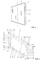
- Unter Bezugnahme auf die
Figuren 4 bis 5 auch mit Blick auf dieFiguren 1 bis 3 wird nun der Aufbau der Betätigungsvorrichtung 1 genauer erläutert. - In den
Figuren 4 bis 5 erstreckt sich die Aufnahme 12 jeweils entlang der kürzeren Seite der Rahmenelementes, wobei hierbei ein Lichtschein L links und rechts abbegbar ist. Sofern ein Lichtschein L auch oder alternativ nach unten bzw. oben abgebbar sein soll, ist eine entsprechende Aufnahme entlang der längeren Seite anzuordnen. - Die Betätigungsvorrichtung 1 umfasst ein Rahmenelement 2 mit einer Rahmenwand 3, welche Rahmenwand 3 Innenseitig durch eine Innenfläche 4, aussenseitig durch eine Aussenfläche 5, frontseitig durch eine vordere Stirnfläche 6 und Rückseitig durch eine hintere Stirnfläche 7 begrenzt ist. Die Innenfläche 4 begrenzt zudem eine Rahmenöffnung 8, welche vollständig durch das Rahmenelement 2 hindurchgeht. Weiter umfasst die Betätigungsvorrichtung 1 eine vor der vorderen Stirnfläche 6 angeordnete und sich mindestens über die Rahmenöffnung 8 erstreckende Platte 9. Die Platte 9 ist das Element, welches vom Benutzer im eingebauten Zustand wahrgenommen wird. Zur Bereitstellung des Lichtscheins L umfasst die Betätigungsvorrichtung 1 mindestens ein hinter der Platte 9 angeordnetes Leuchtmittel 10. Zudem umfasst die Betätigungsvorrichtung 1 mindestens ein Erfassungselement 11 zur Bereitstellung eines Signals für die Spülvorrichtung. Das Erfassungselement 11 kann aber auch zur Erfassung einer im Badezimmer anwesenden Person dienen.
- Zusammenfassend umfasst die Betätigungsvorrichtung 1 das Rahmenelement 2, die Platte 9, das mindestens eine Leuchtmittel 10 und das mindestens eine Erfassungselement 11.
- Das Rahmenelement 2 umfasst mindestens eine Aufnahme 12 für das Leuchtmittel 10. Die Aufnahme 12 durchdringt mit mindestens einem oder genau einem Durchbruch 13 die Aussenfläche 5 des Rahmenelementes 2. Die Aussenfläche 5 definiert dabei die Aussenseite des Rahmenelementes 2. Über den Durchbruch 13 ist Licht vom Leuchtmittel 10 durch den besagten Durchbruch 13 in der Aussenfläche 5 seitlich zum Rahmenelement 2 abgebbar. Im eingebauten Zustand heisst dies, dass das Licht durch den Durchbruch 10, welcher im Wesentlichen rechtwinklig zur Wand des Badezimmers steht, abgebbar ist. Die Betätigungsvorrichtung 1 kann also, in Anordnung der Aufnahme 12, seitlich einen Lichtschein L abgeben.
- Das Leuchtmittel 10 kann verschiedenartig ausgebildet sein. In einer ersten Variante umfasst das Leuchtmittel 10 mindestens eine Lichtquelle 14, insbesondere in der Form einer Leuchtdiode. Die Leuchtdiode ist dabei derart angeordnet, dass diese das Licht durch den Durchbruch 13 in der Aussenfläche 5 des Rahmenelementes 2 abgibt. In einer weiteren, in den Figuren dargestellten Variante, umfasst das Leuchtmittel 10 mindestens eine Lichtquelle 14, insbesondere eine Leuchtdiode, und mindestens ein Lichtwellenleiter 15 mit mindestens einer Einkoppelfläche 16 und mindestens einer Auskoppelfläche 17. Die Lichtquelle 14 koppelt das von ihr bereitgestellte Licht über die Einkoppelfläche 16 in den Lichtwellenleiter 15 ein und über die Auskoppelfläche 17 wird das Licht aus dem Lichtwellenleiter 15 ausgekoppelt. In der hier gezeigten Ausführungsform sind zwei Lichtquellen 14 angeordnet, welche über zwei Einkoppelflächen 16 das Licht in den Lichtwellenleiter 15 einkoppeln. Es ist aber nur eine einzige Auskoppelfläche 17 angeordnet, über welche das Licht wieder ausgekoppelt wird. Die Auskoppelfläche 17 erstreckt sich vollständig über den Durchbruch 13.
- Die Lichtquelle 14 und der Lichtwellenleiter 15, sofern vorhanden, sind in der besagten Aufnahme 12 angeordnet.
- Die Auskoppelfläche 17 des Lichtwellenleiters 15 ist dabei bündig mit der Aussenfläche 5 des Rahmenelementes 2. Die Auskoppelfläche 17 liegt also in einer Ebene, welche durch die Aussenfläche 5 aufgespannt wird. Die Auskoppelfläche 17 stellt dabei einen Teil der Aussenfläche 5 im Bereich des Durchbruches 13 bereit.
- In einer anderen Ausführungsform kann der Durchbruch 13 auch mit einem transparenten oder transluzenten Fenster verschlossen sein. Das Leuchtmittel 10, insbesondere der Lichtwellenleiter 15 oder die Leuchtquelle 14 sind dabei hinter diesem Fenster angeordnet. Das Fenster verläuft ebenfalls parallel zur Aussenfläche und erstreckt sich über den Durchbruch 13.
- In einer besonders bevorzugten Ausführungsform sind pro Aussenfläche 5 des Rahmenelementes 2 jeweils zwei Lichtwellenleiter 15 getrennt voneinander angeordnet. Jeweils mindestens eine Lichtquelle 14 koppelt dabei Licht in den jeweiligen Lichtwellenleiter 15 ein. Die Lichtwellenleiter 15 sind vorzugsweise unterschiedlich lang ausgebildet, sodass dem Benutzer die Position des Erfassungselementes 11 für eine Vollmengenspülung und die Position des Erfassungselementes 11 für eine Teilmengenspülung signalisiert werden kann.
- In einer anderen bevorzugten Ausführungsform, so wie sie beispielsweise in den Figuren gezeigt wird, ist pro Aussenfläche 5 des Rahmenelementes 2 ein einziger Lichtwellenleiter 15 mit mindestens einer Lichtquelle 14 angeordnet. Der Lichtwellenleiter 15 erstreckt sich dabei im Wesentlichen vollständig über die jeweilige Seite des Rahmenelementes 2. Hierdurch kann ein besonders homogener Lichtschein L bereitgestellt werden.
- Der Durchbruch 13 erstreckt sich vorzugsweise ausschliesslich über einen Teilbereich der Aussenfläche 5. Mit anderen Worten gesagt wird der Durchbruch 13 durch Teile der Aussenfläche 5 seitlich begrenzt. Vorzugsweise grenzt der Durchbruch an die vordere Stirnfläche 6 des Rahmenelementes 2 direkt und unmittelbar an. In einer alternativen, hier nicht gezeigten Ausführungsform, kann der Durchbruch 13 auch vollständig von der Aussenfläche 5 umschlossen sein. Der Durchbruch liegt dann besonders bevorzugt mittig in der Aussenfläche 5. In einer weiteren nicht gezeigten Ausführungsform ist der Durchbruch 13 derart angeordnet, dass sich dieser unmittelbar an die hintere Stirnfläche 7 angrenzt.
- Bei der Ausführungsform, bei welcher der Durchbruch 13 an die vordere Stirnfläche 6 angrenzt, erstreckt sich die Aufnahme 12 von der vorderen Stirnfläche 6 in die Rahmenwand hinein und weist einen Boden 18 auf, welcher beabstandet zur vorderen Stirnfläche 6 und zur hinteren Stirnfläche 7 liegt. Auf dem Boden 18 können die Leuchtmittel 10 entsprechend aufliegen. Nach vorne hin stellt die Platte 9 einen Anschlag für das Leuchtmittel 10 bereit. Folglich wird also das Leuchtmittel 10 zwischen dem Boden 18 und der Platte 9 gelagert, insbesondere leicht geklemmt. Dies kann in der
Figur 6 gut erkannt werden. Mit anderen Worten gesagt ist das Leuchtmittel 10 zwischen dem Boden 18 und der Platte 9 angeordnet und steht sowohl mit dem Boden 18 und vorzugsweise auch mit der Platte in direktem Kontakt. - Weiter umfasst die Aufnahme 12, wie in der
Figur 4 und5 gezeigt, mindestens einen Anschlagsabsatz 19. Der Anschlagsabsatz 19 stellt einen Anschlag für das Leuchtmittel 10, insbesondere für den Leuchtwellenleiter 15, gegen eine Bewegung in Richtung der Aussenfläche 5 bereit. Der Anschlagsabsatz 19 ist dabei derart angeordnet, dass dieser bezüglich der Aufnahme 12 den Durchbruch 13 leicht verkleinert, sodass beim Anschlag gegen das Herausfallen des Leuchtmittels 10 aus der Aufnahme 12 durch den Durchbruch 13 bereitgestellt wird. Gegenüber dem Anschlagsabsatz 19 weist die Aufnahme 12 eine Rückwand 23 auf. Welche ebenfalls als Anschlag für das Leuchtmittel 10 wirkt. Seitlich wird die Aufnahme 12 durch eine Seitenwand 22 begrenzt. - Zusammenfassend kann gesagt werden, dass das Leuchtmittel 10 vorzugsweise formschlüssig durch die Platte 9, den Anschlagsabsatz 19, die Rückwand 23 und den Boden 18 im Rahmenelement 2 gehalten wird.
- Im Bereich des Anschlagabsatzes 19 ist in der vorliegenden Ausführungsform jeweils die Lichtquelle 14 angeordnet, welche das Licht über die Einkoppelfläche 16 in den Lichtwellenleiter 15 einkoppelt.
- Der Lichtwellenleiter 15 umfasst einen Ausschnitt 24, welcher im Wesentlichen komplementär zum Anschlagsabsatz 19 ist und mit diesem zusammenarbeitet. In der vorliegenden Ausführungsform sind oben und unten jeweils ein Ausschnitt 24 angeordnet. Im Bereich des Ausschnittes 24 liegt zudem die Einkoppelfläche 16.
- Das Leuchtmittel 10 kann entweder formschlüssig in der Aufnahme liegen und in analoger Weise wie der Lichtwellenleiter 15 durch die Platte und die Aufnahme gesichert sein oder das Leuchtmittel 10 kann auch stoffschlüssig in der Aufnahme 12 gehalten werden.
- Das Rahmenelement 2 ist in Richtung der Flächennormalen N auf die Platte 9 betrachtet vorzugsweise ein Rechteck. Die Aufnahme 12 kann an verschiedenen Seiten des Rechteckes angeordnet sein. In einer ersten Ausführungsform ist die Aufnahme 12 an zwei gegenüberliegenden Seiten des Rechteckes angeordnet. Dabei kann das Licht entweder über die kurze Seite des Rechteckes oder über die lange Seite des Rechteckes abgegeben werden. Es ist also eine Beleuchtung oben unten oder links recht möglich.
- In einer alternativen Ausführungsform ist die Aufnahme 12 von ausschliesslich einer Seite des Rechtecks angeordnet. Somit ist der Lichtschein auch ausschliesslich über eine Seite des Rechteckes abgebbar.
- In einer weiteren Ausführungsform ist die Aufnahme an zwei gegenüberliegenden Seiten des Rechteckes und an mindestens einer weiteren Seite des Rechteckes angeordnet. Somit kann das Licht also über drei Seiten des Rechteckes abgegeben werden.
- In einer weiteren Ausführungsform ist die Aufnahme 12 an allen vier Seiten des Rechteckes angeordnet und es ist ein Lichtschein L rund um die Betätigungsvorrichtung 1 herum abgebbar.
- Das Rahmenelement 2 kann aber auch eine andere Form aufweisen. Beispielsweise kann das Rahmenelement 2 auch ein Quadrat sein, wobei die Anordnung der Aufnahme 12 bezüglich der entsprechenden Seiten identisch zur oben beschriebenen Konfiguration zum rechteckig ausgebildeten Rahmelement sein kann. Ebenfalls wäre es denkbar, das Rahmenelement 2 elliptisch oder rund auszubilden.
- Das Leuchtmittel 10, insbesondere der Lichtwellenleiter 15, erstreckt sich vorzugsweise im Wesentlich über die gesamte Länge A der entsprechenden Seite in welche die Aufnahme 12 angeordnet ist. Somit erstreckt sich auch die Aufnahme 12 beziehungsweise der Durchbruch 13 im Wesentlichen über gesamte Länge A. Im Wesentlichen heisst in diesem Zusammenhang, dass sich der Durchbruch 13 abgesehen von einem kleinen Rand 25, hier im Bereich des Anschlagsabsatzes 19 über dem grössten Teil der gesamten Länge erstreckt.
- In einer besonders bevorzugten Ausführungsform erstreckt sich das Leuchtmittel 10, insbesondere der Lichtwellenleiter 15, im Wesentlichen über eine Länge A von mindestens 60% oder mindestens 80% der Länge der entsprechenden Seite. Auch wäre es denkbar, dass der Lichtwellenleiter bezüglich der Länge A der entsprechenden Seite des Rahmenelementes 2 wesentlich kürzer ausgebildet ist.
- Von den
Figur 4 und5 kann gut erkannt werden, dass ein Erfassungselement 11 hinter der Platte im Bereich der Rahmenöffnung 8 angeordnet ist. Hier sind zwei Erfassungselemente 11 angeordnet. Besonders bevorzugt sind die Erfassungselemente 11 zwei Sensoren, welche die Präsenz eines Benutzers erfassen können und welche bei einer Berührung der Platte 9 eine entsprechende Spülung auslösen. - In einer alternativen, hier nicht gezeigten, Ausführungsform ist das Erfassungselement 11 ein in der Platte 9 gelagerte und relativ zur Platte 9 bewegbare Taste. Die Taste wirkt dabei auf Drückerstangen, welche mit dem Abflussventil zusammenarbeiten.
- Weiter umfasst das Rahmenelement 2 Lagerungsabschnitte 20 zur Lagerung einer Leiterplatte 21. Die Leiterplatte 21 liegt in der Rahmenöffnung 8. Auf der Leiterplatte 21 sind die besagten Erfassungselemente 11 angeordnet. Weiter umfasst die Leiterplatte zudem mindestens eine Steuerungseinheit zur Steuerung der Leuchtmittel 10, welche elektrisch mit der Steuerungseinheit in Verbindung stehen. Die Leiterplatte 21 kann sich dabei über den gesamten Querschnitt der Rahmenöffnung 8 oder nur über einen Teilquerschnitt der Rahmenöffnung 8 erstrecken.
- Bezüglich der Ausdehnung der Platte 9 kann von der
Figur 5 gut erkannt werden, dass sich diese Seitlich über das Rahmenelement 2 erstreckt. Von vorne in Richtung der Flächennormalen N heisst dies, dass sich die Platte 9 auf allen vier Seiten über das Rahmenelement 2, also über die Aussenfläche 5 hinaus, erstreckt. -
- 1
- Betätigungsvorrichtung
- 2
- Rahmenelement
- 3
- Rahmenwand
- 4
- Innenfläche
- 5
- Aussenfläche
- 6
- vordere Stirnfläche
- 7
- hintere Stirnfläche
- 8
- Rahmenöffnung
- 9
- Platte
- 10
- Leuchtmittel
- 11
- Erfassungselement
- 12
- Aufnahme
- 13
- Durchbruch
- 14
- Lichtquelle
- 15
- Lichtwellenleiter
- 16
- Einkoppelfläche
- 17
- Auskoppelfläche
- 18
- Boden
- 19
- Anschlagsabsatz
- 20
- Lagerungsabschnitt
- 21
- Leiterplatte
- 22
- Seitenwand
- 23
- Rückwand
- 24
- Ausschnitt
- 25
- Rand
- L
- Lichtschein
- N
- Flächennormale
- A
- Länge
Claims (16)
- Betätigungsvorrichtung (1) für die Betätigung einer Spülvorrichtung einer Toilette oder eines Urinals, umfassend
ein Rahmenelement (2) mit einer Rahmenwand (3), welche Rahmenwand (3) innenseitig durch eine Innenfläche (4), aussenseitig durch eine Aussenfläche (5), frontseitig durch eine vordere Stirnfläche (6) und rückseitig durch eine hintere Stirnfläche (7) begrenzt ist, welche Innenfläche (4) eine Rahmenöffnung (8) begrenzt,
eine vor der, insbesondere in Kontakt mit der, vorderen Stirnfläche (6) angeordnete sich mindestens über die Rahmenöffnung (8) erstreckende Platte (9),
mindestens ein hinter der Platte (9) angeordnetes Leuchtmittel (10) und mindestens ein Erfassungselement (11) zur Bereitstellung eines Signals für die Spülvorrichtung,
dadurch gekennzeichnet, dass
das Rahmenelement (2) mindestens eine Aufnahme (12) für das Leuchtmittel (10) umfasst, wobei die Aufnahme (12) mit mindestens einem oder genau einem Durchbruch (13) die Aussenfläche (5) des Rahmenelementes (2) durchdringt, so dass Licht vom Leuchtmittel (10) durch den besagten Durchbruch (13) in der Aussenfläche (5) seitlich zum Rahmenelement (2) abgebbar ist. - Betätigungsvorrichtung (1) nach Anspruch 1, dadurch gekennzeichnet, dass das Leuchtmittel (10) mindestens eine Lichtquelle (14), insbesondere eine Leuchtdiode, und vorzugsweise mindestens ein Lichtwellenleiter (15) mit mindestens einer Einkoppelfläche (16) und mindestens einer Auskoppelfläche (17) umfasst, wobei die Lichtquelle (14) das Licht über die Einkoppelfläche (16) in den Lichtwellenleiter (15) einkoppelt und über die Auskoppelfläche (17) aus dem Lichtwellenleiter (15) auskoppelt und wobei der die Lichtquelle (14) und/oder der Lichtwellenleiter (15) in der besagten Aufnahme (12) angeordnet sind.
- Betätigungsvorrichtung (1) nach Anspruch 2, dadurch gekennzeichnet, dass pro Lichtwellenleiter (15) mindestens zwei Lichtquellen (14) angeordnet sind, welche das Licht über mindestens zwei unterschiedliche Einkoppelflächen (16) einkoppeln.
- Betätigungsvorrichtung (1) nach einem der Ansprüche 2 bis 3, dadurch gekennzeichnet, dass pro Aussenfläche (5) des Rahmenelementes (2) mindestens zwei oder genau zwei Lichtwellenleiter (15) mit jeweils mindestens einer Lichtquelle (14) angeordnet sind, wobei die Lichtwellenleiter (15) vorzugsweise unterschiedlich lang oder gleich lang zueinander ausgebildet sind, und/oder dass pro Aussenfläche (5) des Rahmenelementes (2) ein einziger Lichtwellenleiter (15) mit mindestens einer Lichtquelle (14) angeordnet ist.
- Betätigungsvorrichtung (1) nach einem der vorhergehenden Ansprüche, dadurch gekennzeichnet, dass die Auskoppelfläche (17) des Lichtwellenleiters (15) bündig mit der Aussenfläche (5) ist oder dass der Durchbruch (13) mit einem transparenten oder transluzenten Fenster verschlossen ist, welches Fenster bündig zur Aussenfläche (5) verläuft.
- Betätigungsvorrichtung (1) nach einem der vorhergehenden Ansprüche, dadurch gekennzeichnet, dass sich der Durchbruch (13) ausschliesslich über einen Teilbereich der Aussenfläche (5) erstreckt, wobei der Durchbruch (13) vorzugsweise an die vordere Stirnfläche (6) des Rahmenelementes (2) direkt und unmittelbar angrenzend ausgebildet ist, oder wobei der Durchbruch (13) von der Aussenfläche (5) umschlossen ist, oder wobei der Durchbruch (13) vorzugsweise an die hintere Stirnfläche (7) des Rahmenelementes (2) direkt und unmittelbar angrenzend ausgebildet.
- Betätigungsvorrichtung (1) nach einem der vorhergehenden Ansprüche, dadurch gekennzeichnet, dass die Aufnahme (12) sich von der vorderen Stirnfläche (6) in die Rahmenwand (3) hineinerstreckt und einen Boden (18) aufweist, welcher beabstandet zur vorderen Stirnfläche (6) und hinteren Stirnfläche (7) liegt.
- Betätigungsvorrichtung (1) nach einem der vorhergehenden Ansprüche, dadurch gekennzeichnet, dass die Aufnahme (12) mindestens einen Anschlagsabsatz (19) und gegenüber des Anschlagsabsatzes (19) eine Rückwand (23) aufweist, wobei der Anschlagsabsatz (19) und die Rückwand (23) einen Anschlag für das Leuchtmittel (10), insbesondere für den Lichtwellenleiter (15), bereitstellen.
- Betätigungsvorrichtung (1) nach einem der vorhergehenden Ansprüche, dadurch gekennzeichnet, dass die Platte (9) formschlüssig und/oder stoffschlüssig mit dem Rahmenelement (2) verbunden ist und einen Anschlag für das Leuchtmittel (10), insbesondere für den Lichtwellenleiter (15), bereitstellt und/oder dass das Leuchtmittel (10), insbesondere der Lichtwellenleiter (15), mit der zur Platte (9) zugewandten Seite in direktem Kontakt mit der Platte (9) steht.
- Betätigungsvorrichtung (1) nach einem der vorhergehenden Ansprüchen, dadurch gekennzeichnet, dass die Platte (9) seitlich über das Rahmenelement (2), insbesondere über die Aussenfläche (5), hervorsteht.
- Betätigungsvorrichtung (1) nach einem der vorhergehenden Ansprüche, dadurch gekennzeichnet, dass das Leuchtmittel (10) formschlüssig und/oder stoffschlüssig in der Aufnahme (12) gehalten wird.
- Betätigungsvorrichtung (1) nach einem der vorhergehenden Ansprüche, dadurch gekennzeichnet, dass das Rahmenelement (2) in Richtung der Flächennormalen (N) auf die Platte (9) betrachtet ein Rechteck oder ein Quadrat ist,
wobei jeweils eine Aufnahme (12) an zwei gegenüberliegenden Seiten des Rechteckes bzw. des Quadrates angeordnet sind, oder
wobei die Aufnahme (12) an ausschliesslich einer Seite des Rechteckes bzw. des Quadrates angeordnet ist, oder
wobei jeweils eine Aufnahme (12) an zwei gegenüberliegenden Seiten des Rechteckes bzw. des Quadrates angeordnet ist und an mindestens einer weiteren Seite des Rechteckes bzw. des Quadrates angeordnet ist, oder
wobei jeweils eine Aufnahme (12) an allen vier Seiten des Rechteckes bzw. des Quadrates angeordnet ist. - Betätigungsvorrichtung (1) nach einem Ansprüche 12, dadurch gekennzeichnet, dass das Leuchtmittel (10), insbesondere der Lichtwellenleiter (15), sich im Wesentlichen über die gesamte Länge (A) der entsprechenden Seite erstreckt, oder dass sich das Leuchtmittel (10), insbesondere der Lichtwellenleiter (15), sich im Wesentlichen über eine Länge (A) von mindestens 60% oder mindestens 80% der Länge der entsprechenden Seite erstreckt.
- Betätigungsvorrichtung (1) nach einem der vorhergehenden Ansprüche, dadurch gekennzeichnet, dass das Erfassungselement (11) ein hinter der Platte (9) angeordneter Sensor ist, oder dass das Erfassungselement (11) eine in der Platte (9) gelagerte und relativ zur Platte (9) bewegbare Taste ist, und/oder dass das Rahmenelement (2) Lagerungsabschnitte (20) zur Lagerung einer Leiterplatte (21) aufweist, auf welcher Leiterplatte (21) mindestens eine Steuerungseinheit und ggf. das Erfassungselement (11), insbesondere der Sensor, angeordnet ist.
- Anordnung umfassend eine Betätigungsvorrichtung (1) nach einem der vorhergehenden Ansprüche und ein mit der Betätigungsvorrichtung funktional oder physisch in Verbindung stehender Spülkasten.
- Anordnung nach Anspruch 15, dadurch gekennzeichnet, dass die Anordnung weiterhin mindestens ein Befestigungselement umfasst, welches an eine Gebäudewand befestigbar ist und welches eine Aufnahme für die Betätigungsvorrichtung bereitstellt.
Priority Applications (1)
| Application Number | Priority Date | Filing Date | Title |
|---|---|---|---|
| EP14161161.6A EP2921597B1 (de) | 2014-03-21 | 2014-03-21 | Betätigungsvorrichtung |
Applications Claiming Priority (1)
| Application Number | Priority Date | Filing Date | Title |
|---|---|---|---|
| EP14161161.6A EP2921597B1 (de) | 2014-03-21 | 2014-03-21 | Betätigungsvorrichtung |
Publications (2)
| Publication Number | Publication Date |
|---|---|
| EP2921597A1 true EP2921597A1 (de) | 2015-09-23 |
| EP2921597B1 EP2921597B1 (de) | 2020-05-13 |
Family
ID=50336223
Family Applications (1)
| Application Number | Title | Priority Date | Filing Date |
|---|---|---|---|
| EP14161161.6A Active EP2921597B1 (de) | 2014-03-21 | 2014-03-21 | Betätigungsvorrichtung |
Country Status (1)
| Country | Link |
|---|---|
| EP (1) | EP2921597B1 (de) |
Cited By (5)
| Publication number | Priority date | Publication date | Assignee | Title |
|---|---|---|---|---|
| EP3705648A1 (de) * | 2019-03-08 | 2020-09-09 | Viega Technology GmbH & Co. KG | Befestigungsrahmen für eine betätigungsplatte zur betätigung eines ventils einer sanitärinstallation sowie betätigungsvorrichtung mit einem solchen befestigungsrahmen und einer betätigungsplatte |
| DE102019001878A1 (de) * | 2019-03-13 | 2020-09-17 | René Schönig | Vorbauelement |
| IT201900009210A1 (it) * | 2019-06-17 | 2020-12-17 | Kariba Spa | Placca di comando per sanitari da bagno |
| US20210003708A1 (en) * | 2019-07-02 | 2021-01-07 | Geberit International Ag | Actuation device with user recognition |
| EP3875700A1 (de) * | 2020-03-05 | 2021-09-08 | TECE GmbH | Berührungslos betätigbare betätigungsplatte |
Citations (5)
| Publication number | Priority date | Publication date | Assignee | Title |
|---|---|---|---|---|
| JP2010110570A (ja) * | 2008-11-10 | 2010-05-20 | Panasonic Electric Works Co Ltd | 洗面化粧台 |
| US20110155934A1 (en) * | 2002-03-05 | 2011-06-30 | Fatih Guler | Automatic bathroom flushers |
| JP2011152330A (ja) * | 2010-01-28 | 2011-08-11 | Lixil Corp | 照明付き鏡装置 |
| EP2497868A1 (de) * | 2011-03-09 | 2012-09-12 | Geberit International AG | Vorrichtung zur elektrischen Auslösung einer Wasserabgabe |
| EP2578758A2 (de) | 2011-10-06 | 2013-04-10 | Geberit International AG | Verfahren zum Einstellen eines Parameters sowie hierzu verwendetes Betätigungselement |
-
2014
- 2014-03-21 EP EP14161161.6A patent/EP2921597B1/de active Active
Patent Citations (5)
| Publication number | Priority date | Publication date | Assignee | Title |
|---|---|---|---|---|
| US20110155934A1 (en) * | 2002-03-05 | 2011-06-30 | Fatih Guler | Automatic bathroom flushers |
| JP2010110570A (ja) * | 2008-11-10 | 2010-05-20 | Panasonic Electric Works Co Ltd | 洗面化粧台 |
| JP2011152330A (ja) * | 2010-01-28 | 2011-08-11 | Lixil Corp | 照明付き鏡装置 |
| EP2497868A1 (de) * | 2011-03-09 | 2012-09-12 | Geberit International AG | Vorrichtung zur elektrischen Auslösung einer Wasserabgabe |
| EP2578758A2 (de) | 2011-10-06 | 2013-04-10 | Geberit International AG | Verfahren zum Einstellen eines Parameters sowie hierzu verwendetes Betätigungselement |
Cited By (7)
| Publication number | Priority date | Publication date | Assignee | Title |
|---|---|---|---|---|
| EP3705648A1 (de) * | 2019-03-08 | 2020-09-09 | Viega Technology GmbH & Co. KG | Befestigungsrahmen für eine betätigungsplatte zur betätigung eines ventils einer sanitärinstallation sowie betätigungsvorrichtung mit einem solchen befestigungsrahmen und einer betätigungsplatte |
| DE102019001578A1 (de) * | 2019-03-08 | 2020-09-10 | Viega Technology Gmbh & Co. Kg | Befestigungsrahmen für eine Betätigungsgsplatte zur Betätigung eines Ventils einer Sanitärinstallation sowie Betätigungsvorrichtung mit einem solchen Befestigungsrahmen und einer Betätigungsplatte |
| DE102019001878A1 (de) * | 2019-03-13 | 2020-09-17 | René Schönig | Vorbauelement |
| DE102019001878B4 (de) * | 2019-03-13 | 2020-11-05 | René Schönig | Vorbauelement |
| IT201900009210A1 (it) * | 2019-06-17 | 2020-12-17 | Kariba Spa | Placca di comando per sanitari da bagno |
| US20210003708A1 (en) * | 2019-07-02 | 2021-01-07 | Geberit International Ag | Actuation device with user recognition |
| EP3875700A1 (de) * | 2020-03-05 | 2021-09-08 | TECE GmbH | Berührungslos betätigbare betätigungsplatte |
Also Published As
| Publication number | Publication date |
|---|---|
| EP2921597B1 (de) | 2020-05-13 |
Similar Documents
| Publication | Publication Date | Title |
|---|---|---|
| EP2921597B1 (de) | Betätigungsvorrichtung | |
| DE102009004985A1 (de) | Verkleidungsteil mit Sensor | |
| DE102009033538A1 (de) | Bedieneinrichtung für ein Elektrogerät | |
| DE102007010023A1 (de) | Fahrzeugleuchte | |
| EP2322962A1 (de) | Dekorelement mit einem Lichtleiter | |
| DE102014003505A1 (de) | Kraftfahrzeugtürschloss mit Kindersicherung | |
| AT504606B1 (de) | Schalttafel mit wenigstens einem schalter | |
| DE102007054347B3 (de) | Manuell betätigbarer Schalter | |
| EP1383242A2 (de) | Sensitiver Schalter zum Betätigen eines Leuchtmittels | |
| DE10225016B4 (de) | Beleuchtbare Betätigungsknopfanordnung | |
| DE202006003392U1 (de) | Fahrzeugleuchte | |
| DE202008005518U1 (de) | Betätigungsplatte für Sanitärinstallationen | |
| DE202007006772U1 (de) | Ladebordwand | |
| EP3262242B1 (de) | Beleuchtete betätigungsplatte | |
| DE10234300B4 (de) | Sicherungs- und Überwachungsvorrichtung für Türen, Fenster oder dergleichen | |
| DE102015114632A1 (de) | Signalleuchte für Fahrzeuge | |
| DE202013101827U1 (de) | Beleuchtungsanordnung mit länglichem Leuchtengehäuse | |
| EP2770127A1 (de) | Montageeinrichtung für einen Sanitärkörper | |
| EP2631528A1 (de) | LED-Leuchtröhre | |
| EP1662056A2 (de) | Betätigungsvorrichtung für Sanitärarmatur. | |
| WO2022101250A1 (de) | Aufzugskabine und uvc-strahlungseinrichtung für eine aufzugskabine | |
| EP2650606A1 (de) | LED-Leuchte | |
| DE202010000087U1 (de) | Leuchteinheit insbesondere für Griffe u.dgl. | |
| DE10014023A1 (de) | Hinweis-und Sicherheitsleuchte | |
| DE102021105928A1 (de) | Akustisch optische Warneinrichtung, insbesondere für Einsatzfahrzeuge |
Legal Events
| Date | Code | Title | Description |
|---|---|---|---|
| PUAI | Public reference made under article 153(3) epc to a published international application that has entered the european phase |
Free format text: ORIGINAL CODE: 0009012 |
|
| AK | Designated contracting states |
Kind code of ref document: A1 Designated state(s): AL AT BE BG CH CY CZ DE DK EE ES FI FR GB GR HR HU IE IS IT LI LT LU LV MC MK MT NL NO PL PT RO RS SE SI SK SM TR |
|
| AX | Request for extension of the european patent |
Extension state: BA ME |
|
| 17P | Request for examination filed |
Effective date: 20160229 |
|
| RBV | Designated contracting states (corrected) |
Designated state(s): AL AT BE BG CH CY CZ DE DK EE ES FI FR GB GR HR HU IE IS IT LI LT LU LV MC MK MT NL NO PL PT RO RS SE SI SK SM TR |
|
| GRAP | Despatch of communication of intention to grant a patent |
Free format text: ORIGINAL CODE: EPIDOSNIGR1 |
|
| STAA | Information on the status of an ep patent application or granted ep patent |
Free format text: STATUS: GRANT OF PATENT IS INTENDED |
|
| INTG | Intention to grant announced |
Effective date: 20191213 |
|
| GRAS | Grant fee paid |
Free format text: ORIGINAL CODE: EPIDOSNIGR3 |
|
| GRAA | (expected) grant |
Free format text: ORIGINAL CODE: 0009210 |
|
| STAA | Information on the status of an ep patent application or granted ep patent |
Free format text: STATUS: THE PATENT HAS BEEN GRANTED |
|
| AK | Designated contracting states |
Kind code of ref document: B1 Designated state(s): AL AT BE BG CH CY CZ DE DK EE ES FI FR GB GR HR HU IE IS IT LI LT LU LV MC MK MT NL NO PL PT RO RS SE SI SK SM TR |
|
| REG | Reference to a national code |
Ref country code: GB Ref legal event code: FG4D Free format text: NOT ENGLISH |
|
| REG | Reference to a national code |
Ref country code: CH Ref legal event code: EP |
|
| REG | Reference to a national code |
Ref country code: DE Ref legal event code: R096 Ref document number: 502014014167 Country of ref document: DE |
|
| REG | Reference to a national code |
Ref country code: AT Ref legal event code: REF Ref document number: 1270449 Country of ref document: AT Kind code of ref document: T Effective date: 20200615 |
|
| REG | Reference to a national code |
Ref country code: CH Ref legal event code: NV Representative=s name: ISLER AND PEDRAZZINI AG, CH |
|
| REG | Reference to a national code |
Ref country code: NL Ref legal event code: FP |
|
| REG | Reference to a national code |
Ref country code: LT Ref legal event code: MG4D |
|
| PG25 | Lapsed in a contracting state [announced via postgrant information from national office to epo] |
Ref country code: GR Free format text: LAPSE BECAUSE OF FAILURE TO SUBMIT A TRANSLATION OF THE DESCRIPTION OR TO PAY THE FEE WITHIN THE PRESCRIBED TIME-LIMIT Effective date: 20200814 Ref country code: NO Free format text: LAPSE BECAUSE OF FAILURE TO SUBMIT A TRANSLATION OF THE DESCRIPTION OR TO PAY THE FEE WITHIN THE PRESCRIBED TIME-LIMIT Effective date: 20200813 Ref country code: FI Free format text: LAPSE BECAUSE OF FAILURE TO SUBMIT A TRANSLATION OF THE DESCRIPTION OR TO PAY THE FEE WITHIN THE PRESCRIBED TIME-LIMIT Effective date: 20200513 Ref country code: PT Free format text: LAPSE BECAUSE OF FAILURE TO SUBMIT A TRANSLATION OF THE DESCRIPTION OR TO PAY THE FEE WITHIN THE PRESCRIBED TIME-LIMIT Effective date: 20200914 Ref country code: IS Free format text: LAPSE BECAUSE OF FAILURE TO SUBMIT A TRANSLATION OF THE DESCRIPTION OR TO PAY THE FEE WITHIN THE PRESCRIBED TIME-LIMIT Effective date: 20200913 Ref country code: LT Free format text: LAPSE BECAUSE OF FAILURE TO SUBMIT A TRANSLATION OF THE DESCRIPTION OR TO PAY THE FEE WITHIN THE PRESCRIBED TIME-LIMIT Effective date: 20200513 Ref country code: SE Free format text: LAPSE BECAUSE OF FAILURE TO SUBMIT A TRANSLATION OF THE DESCRIPTION OR TO PAY THE FEE WITHIN THE PRESCRIBED TIME-LIMIT Effective date: 20200513 |
|
| PG25 | Lapsed in a contracting state [announced via postgrant information from national office to epo] |
Ref country code: HR Free format text: LAPSE BECAUSE OF FAILURE TO SUBMIT A TRANSLATION OF THE DESCRIPTION OR TO PAY THE FEE WITHIN THE PRESCRIBED TIME-LIMIT Effective date: 20200513 Ref country code: BG Free format text: LAPSE BECAUSE OF FAILURE TO SUBMIT A TRANSLATION OF THE DESCRIPTION OR TO PAY THE FEE WITHIN THE PRESCRIBED TIME-LIMIT Effective date: 20200813 Ref country code: RS Free format text: LAPSE BECAUSE OF FAILURE TO SUBMIT A TRANSLATION OF THE DESCRIPTION OR TO PAY THE FEE WITHIN THE PRESCRIBED TIME-LIMIT Effective date: 20200513 Ref country code: LV Free format text: LAPSE BECAUSE OF FAILURE TO SUBMIT A TRANSLATION OF THE DESCRIPTION OR TO PAY THE FEE WITHIN THE PRESCRIBED TIME-LIMIT Effective date: 20200513 |
|
| PG25 | Lapsed in a contracting state [announced via postgrant information from national office to epo] |
Ref country code: AL Free format text: LAPSE BECAUSE OF FAILURE TO SUBMIT A TRANSLATION OF THE DESCRIPTION OR TO PAY THE FEE WITHIN THE PRESCRIBED TIME-LIMIT Effective date: 20200513 |
|
| PG25 | Lapsed in a contracting state [announced via postgrant information from national office to epo] |
Ref country code: DK Free format text: LAPSE BECAUSE OF FAILURE TO SUBMIT A TRANSLATION OF THE DESCRIPTION OR TO PAY THE FEE WITHIN THE PRESCRIBED TIME-LIMIT Effective date: 20200513 Ref country code: ES Free format text: LAPSE BECAUSE OF FAILURE TO SUBMIT A TRANSLATION OF THE DESCRIPTION OR TO PAY THE FEE WITHIN THE PRESCRIBED TIME-LIMIT Effective date: 20200513 Ref country code: SM Free format text: LAPSE BECAUSE OF FAILURE TO SUBMIT A TRANSLATION OF THE DESCRIPTION OR TO PAY THE FEE WITHIN THE PRESCRIBED TIME-LIMIT Effective date: 20200513 Ref country code: EE Free format text: LAPSE BECAUSE OF FAILURE TO SUBMIT A TRANSLATION OF THE DESCRIPTION OR TO PAY THE FEE WITHIN THE PRESCRIBED TIME-LIMIT Effective date: 20200513 Ref country code: CZ Free format text: LAPSE BECAUSE OF FAILURE TO SUBMIT A TRANSLATION OF THE DESCRIPTION OR TO PAY THE FEE WITHIN THE PRESCRIBED TIME-LIMIT Effective date: 20200513 Ref country code: IT Free format text: LAPSE BECAUSE OF FAILURE TO SUBMIT A TRANSLATION OF THE DESCRIPTION OR TO PAY THE FEE WITHIN THE PRESCRIBED TIME-LIMIT Effective date: 20200513 Ref country code: RO Free format text: LAPSE BECAUSE OF FAILURE TO SUBMIT A TRANSLATION OF THE DESCRIPTION OR TO PAY THE FEE WITHIN THE PRESCRIBED TIME-LIMIT Effective date: 20200513 |
|
| REG | Reference to a national code |
Ref country code: DE Ref legal event code: R097 Ref document number: 502014014167 Country of ref document: DE |
|
| PG25 | Lapsed in a contracting state [announced via postgrant information from national office to epo] |
Ref country code: PL Free format text: LAPSE BECAUSE OF FAILURE TO SUBMIT A TRANSLATION OF THE DESCRIPTION OR TO PAY THE FEE WITHIN THE PRESCRIBED TIME-LIMIT Effective date: 20200513 Ref country code: SK Free format text: LAPSE BECAUSE OF FAILURE TO SUBMIT A TRANSLATION OF THE DESCRIPTION OR TO PAY THE FEE WITHIN THE PRESCRIBED TIME-LIMIT Effective date: 20200513 |
|
| PLBE | No opposition filed within time limit |
Free format text: ORIGINAL CODE: 0009261 |
|
| STAA | Information on the status of an ep patent application or granted ep patent |
Free format text: STATUS: NO OPPOSITION FILED WITHIN TIME LIMIT |
|
| 26N | No opposition filed |
Effective date: 20210216 |
|
| PGFP | Annual fee paid to national office [announced via postgrant information from national office to epo] |
Ref country code: NL Payment date: 20210319 Year of fee payment: 8 Ref country code: CH Payment date: 20210311 Year of fee payment: 8 |
|
| PG25 | Lapsed in a contracting state [announced via postgrant information from national office to epo] |
Ref country code: SI Free format text: LAPSE BECAUSE OF FAILURE TO SUBMIT A TRANSLATION OF THE DESCRIPTION OR TO PAY THE FEE WITHIN THE PRESCRIBED TIME-LIMIT Effective date: 20200513 |
|
| PGFP | Annual fee paid to national office [announced via postgrant information from national office to epo] |
Ref country code: BE Payment date: 20210319 Year of fee payment: 8 Ref country code: AT Payment date: 20210322 Year of fee payment: 8 |
|
| PG25 | Lapsed in a contracting state [announced via postgrant information from national office to epo] |
Ref country code: MC Free format text: LAPSE BECAUSE OF FAILURE TO SUBMIT A TRANSLATION OF THE DESCRIPTION OR TO PAY THE FEE WITHIN THE PRESCRIBED TIME-LIMIT Effective date: 20200513 |
|
| GBPC | Gb: european patent ceased through non-payment of renewal fee |
Effective date: 20210321 |
|
| PG25 | Lapsed in a contracting state [announced via postgrant information from national office to epo] |
Ref country code: LU Free format text: LAPSE BECAUSE OF NON-PAYMENT OF DUE FEES Effective date: 20210321 Ref country code: IE Free format text: LAPSE BECAUSE OF NON-PAYMENT OF DUE FEES Effective date: 20210321 Ref country code: GB Free format text: LAPSE BECAUSE OF NON-PAYMENT OF DUE FEES Effective date: 20210321 Ref country code: FR Free format text: LAPSE BECAUSE OF NON-PAYMENT OF DUE FEES Effective date: 20210331 |
|
| REG | Reference to a national code |
Ref country code: CH Ref legal event code: PL |
|
| REG | Reference to a national code |
Ref country code: NL Ref legal event code: MM Effective date: 20220401 |
|
| REG | Reference to a national code |
Ref country code: AT Ref legal event code: MM01 Ref document number: 1270449 Country of ref document: AT Kind code of ref document: T Effective date: 20220321 |
|
| REG | Reference to a national code |
Ref country code: BE Ref legal event code: MM Effective date: 20220331 |
|
| PG25 | Lapsed in a contracting state [announced via postgrant information from national office to epo] |
Ref country code: NL Free format text: LAPSE BECAUSE OF NON-PAYMENT OF DUE FEES Effective date: 20220401 Ref country code: LI Free format text: LAPSE BECAUSE OF NON-PAYMENT OF DUE FEES Effective date: 20220331 Ref country code: CH Free format text: LAPSE BECAUSE OF NON-PAYMENT OF DUE FEES Effective date: 20220331 Ref country code: AT Free format text: LAPSE BECAUSE OF NON-PAYMENT OF DUE FEES Effective date: 20220321 |
|
| PG25 | Lapsed in a contracting state [announced via postgrant information from national office to epo] |
Ref country code: BE Free format text: LAPSE BECAUSE OF NON-PAYMENT OF DUE FEES Effective date: 20220331 |
|
| PG25 | Lapsed in a contracting state [announced via postgrant information from national office to epo] |
Ref country code: HU Free format text: LAPSE BECAUSE OF FAILURE TO SUBMIT A TRANSLATION OF THE DESCRIPTION OR TO PAY THE FEE WITHIN THE PRESCRIBED TIME-LIMIT; INVALID AB INITIO Effective date: 20140321 |
|
| PG25 | Lapsed in a contracting state [announced via postgrant information from national office to epo] |
Ref country code: CY Free format text: LAPSE BECAUSE OF FAILURE TO SUBMIT A TRANSLATION OF THE DESCRIPTION OR TO PAY THE FEE WITHIN THE PRESCRIBED TIME-LIMIT Effective date: 20200513 |
|
| PG25 | Lapsed in a contracting state [announced via postgrant information from national office to epo] |
Ref country code: MK Free format text: LAPSE BECAUSE OF FAILURE TO SUBMIT A TRANSLATION OF THE DESCRIPTION OR TO PAY THE FEE WITHIN THE PRESCRIBED TIME-LIMIT Effective date: 20200513 |
|
| PG25 | Lapsed in a contracting state [announced via postgrant information from national office to epo] |
Ref country code: MT Free format text: LAPSE BECAUSE OF FAILURE TO SUBMIT A TRANSLATION OF THE DESCRIPTION OR TO PAY THE FEE WITHIN THE PRESCRIBED TIME-LIMIT Effective date: 20200513 |
|
| PG25 | Lapsed in a contracting state [announced via postgrant information from national office to epo] |
Ref country code: TR Free format text: LAPSE BECAUSE OF FAILURE TO SUBMIT A TRANSLATION OF THE DESCRIPTION OR TO PAY THE FEE WITHIN THE PRESCRIBED TIME-LIMIT Effective date: 20200513 |
|
| PGFP | Annual fee paid to national office [announced via postgrant information from national office to epo] |
Ref country code: DE Payment date: 20260319 Year of fee payment: 13 |