EP2921283B1 - Siegelvorrichtung - Google Patents
Siegelvorrichtung Download PDFInfo
- Publication number
- EP2921283B1 EP2921283B1 EP15160391.7A EP15160391A EP2921283B1 EP 2921283 B1 EP2921283 B1 EP 2921283B1 EP 15160391 A EP15160391 A EP 15160391A EP 2921283 B1 EP2921283 B1 EP 2921283B1
- Authority
- EP
- European Patent Office
- Prior art keywords
- sealing
- contact surface
- sealing device
- punch
- sonotrode
- Prior art date
- Legal status (The legal status is an assumption and is not a legal conclusion. Google has not performed a legal analysis and makes no representation as to the accuracy of the status listed.)
- Active
Links
- 238000007789 sealing Methods 0.000 claims description 85
- 239000004033 plastic Substances 0.000 claims description 37
- 238000004080 punching Methods 0.000 claims description 14
- 238000005520 cutting process Methods 0.000 claims description 11
- 239000000725 suspension Substances 0.000 claims description 9
- 239000002699 waste material Substances 0.000 claims description 5
- 238000006073 displacement reaction Methods 0.000 claims description 3
- 238000003466 welding Methods 0.000 description 10
- 238000004519 manufacturing process Methods 0.000 description 9
- 238000002604 ultrasonography Methods 0.000 description 7
- 239000011888 foil Substances 0.000 description 5
- 238000000034 method Methods 0.000 description 5
- 239000012535 impurity Substances 0.000 description 2
- 230000010354 integration Effects 0.000 description 2
- 239000000463 material Substances 0.000 description 2
- 239000002985 plastic film Substances 0.000 description 2
- 229920006255 plastic film Polymers 0.000 description 2
- 230000000007 visual effect Effects 0.000 description 2
- 239000000853 adhesive Substances 0.000 description 1
- 230000001070 adhesive effect Effects 0.000 description 1
- 238000010924 continuous production Methods 0.000 description 1
- 230000000694 effects Effects 0.000 description 1
- 238000010438 heat treatment Methods 0.000 description 1
- 230000010355 oscillation Effects 0.000 description 1
- 238000004806 packaging method and process Methods 0.000 description 1
Images

Classifications
-
- B—PERFORMING OPERATIONS; TRANSPORTING
- B29—WORKING OF PLASTICS; WORKING OF SUBSTANCES IN A PLASTIC STATE IN GENERAL
- B29C—SHAPING OR JOINING OF PLASTICS; SHAPING OF MATERIAL IN A PLASTIC STATE, NOT OTHERWISE PROVIDED FOR; AFTER-TREATMENT OF THE SHAPED PRODUCTS, e.g. REPAIRING
- B29C65/00—Joining or sealing of preformed parts, e.g. welding of plastics materials; Apparatus therefor
- B29C65/02—Joining or sealing of preformed parts, e.g. welding of plastics materials; Apparatus therefor by heating, with or without pressure
- B29C65/08—Joining or sealing of preformed parts, e.g. welding of plastics materials; Apparatus therefor by heating, with or without pressure using ultrasonic vibrations
-
- B—PERFORMING OPERATIONS; TRANSPORTING
- B65—CONVEYING; PACKING; STORING; HANDLING THIN OR FILAMENTARY MATERIAL
- B65B—MACHINES, APPARATUS OR DEVICES FOR, OR METHODS OF, PACKAGING ARTICLES OR MATERIALS; UNPACKING
- B65B51/00—Devices for, or methods of, sealing or securing package folds or closures; Devices for gathering or twisting wrappers, or necks of bags
- B65B51/10—Applying or generating heat or pressure or combinations thereof
-
- B—PERFORMING OPERATIONS; TRANSPORTING
- B29—WORKING OF PLASTICS; WORKING OF SUBSTANCES IN A PLASTIC STATE IN GENERAL
- B29C—SHAPING OR JOINING OF PLASTICS; SHAPING OF MATERIAL IN A PLASTIC STATE, NOT OTHERWISE PROVIDED FOR; AFTER-TREATMENT OF THE SHAPED PRODUCTS, e.g. REPAIRING
- B29C65/00—Joining or sealing of preformed parts, e.g. welding of plastics materials; Apparatus therefor
- B29C65/74—Joining or sealing of preformed parts, e.g. welding of plastics materials; Apparatus therefor by welding and severing, or by joining and severing, the severing being performed in the area to be joined, next to the area to be joined, in the joint area or next to the joint area
- B29C65/743—Joining or sealing of preformed parts, e.g. welding of plastics materials; Apparatus therefor by welding and severing, or by joining and severing, the severing being performed in the area to be joined, next to the area to be joined, in the joint area or next to the joint area using the same tool for both joining and severing, said tool being monobloc or formed by several parts mounted together and forming a monobloc
- B29C65/7437—Joining or sealing of preformed parts, e.g. welding of plastics materials; Apparatus therefor by welding and severing, or by joining and severing, the severing being performed in the area to be joined, next to the area to be joined, in the joint area or next to the joint area using the same tool for both joining and severing, said tool being monobloc or formed by several parts mounted together and forming a monobloc the tool being a perforating tool
-
- B—PERFORMING OPERATIONS; TRANSPORTING
- B29—WORKING OF PLASTICS; WORKING OF SUBSTANCES IN A PLASTIC STATE IN GENERAL
- B29C—SHAPING OR JOINING OF PLASTICS; SHAPING OF MATERIAL IN A PLASTIC STATE, NOT OTHERWISE PROVIDED FOR; AFTER-TREATMENT OF THE SHAPED PRODUCTS, e.g. REPAIRING
- B29C65/00—Joining or sealing of preformed parts, e.g. welding of plastics materials; Apparatus therefor
- B29C65/74—Joining or sealing of preformed parts, e.g. welding of plastics materials; Apparatus therefor by welding and severing, or by joining and severing, the severing being performed in the area to be joined, next to the area to be joined, in the joint area or next to the joint area
- B29C65/743—Joining or sealing of preformed parts, e.g. welding of plastics materials; Apparatus therefor by welding and severing, or by joining and severing, the severing being performed in the area to be joined, next to the area to be joined, in the joint area or next to the joint area using the same tool for both joining and severing, said tool being monobloc or formed by several parts mounted together and forming a monobloc
- B29C65/7441—Joining or sealing of preformed parts, e.g. welding of plastics materials; Apparatus therefor by welding and severing, or by joining and severing, the severing being performed in the area to be joined, next to the area to be joined, in the joint area or next to the joint area using the same tool for both joining and severing, said tool being monobloc or formed by several parts mounted together and forming a monobloc for making welds and cuts of other than simple rectilinear form
-
- B—PERFORMING OPERATIONS; TRANSPORTING
- B29—WORKING OF PLASTICS; WORKING OF SUBSTANCES IN A PLASTIC STATE IN GENERAL
- B29C—SHAPING OR JOINING OF PLASTICS; SHAPING OF MATERIAL IN A PLASTIC STATE, NOT OTHERWISE PROVIDED FOR; AFTER-TREATMENT OF THE SHAPED PRODUCTS, e.g. REPAIRING
- B29C65/00—Joining or sealing of preformed parts, e.g. welding of plastics materials; Apparatus therefor
- B29C65/74—Joining or sealing of preformed parts, e.g. welding of plastics materials; Apparatus therefor by welding and severing, or by joining and severing, the severing being performed in the area to be joined, next to the area to be joined, in the joint area or next to the joint area
- B29C65/743—Joining or sealing of preformed parts, e.g. welding of plastics materials; Apparatus therefor by welding and severing, or by joining and severing, the severing being performed in the area to be joined, next to the area to be joined, in the joint area or next to the joint area using the same tool for both joining and severing, said tool being monobloc or formed by several parts mounted together and forming a monobloc
- B29C65/7443—Joining or sealing of preformed parts, e.g. welding of plastics materials; Apparatus therefor by welding and severing, or by joining and severing, the severing being performed in the area to be joined, next to the area to be joined, in the joint area or next to the joint area using the same tool for both joining and severing, said tool being monobloc or formed by several parts mounted together and forming a monobloc by means of ultrasonic vibrations
-
- B—PERFORMING OPERATIONS; TRANSPORTING
- B29—WORKING OF PLASTICS; WORKING OF SUBSTANCES IN A PLASTIC STATE IN GENERAL
- B29C—SHAPING OR JOINING OF PLASTICS; SHAPING OF MATERIAL IN A PLASTIC STATE, NOT OTHERWISE PROVIDED FOR; AFTER-TREATMENT OF THE SHAPED PRODUCTS, e.g. REPAIRING
- B29C65/00—Joining or sealing of preformed parts, e.g. welding of plastics materials; Apparatus therefor
- B29C65/74—Joining or sealing of preformed parts, e.g. welding of plastics materials; Apparatus therefor by welding and severing, or by joining and severing, the severing being performed in the area to be joined, next to the area to be joined, in the joint area or next to the joint area
- B29C65/749—Removing scrap
-
- B—PERFORMING OPERATIONS; TRANSPORTING
- B29—WORKING OF PLASTICS; WORKING OF SUBSTANCES IN A PLASTIC STATE IN GENERAL
- B29C—SHAPING OR JOINING OF PLASTICS; SHAPING OF MATERIAL IN A PLASTIC STATE, NOT OTHERWISE PROVIDED FOR; AFTER-TREATMENT OF THE SHAPED PRODUCTS, e.g. REPAIRING
- B29C66/00—General aspects of processes or apparatus for joining preformed parts
- B29C66/01—General aspects dealing with the joint area or with the area to be joined
- B29C66/05—Particular design of joint configurations
- B29C66/10—Particular design of joint configurations particular design of the joint cross-sections
- B29C66/11—Joint cross-sections comprising a single joint-segment, i.e. one of the parts to be joined comprising a single joint-segment in the joint cross-section
- B29C66/112—Single lapped joints
- B29C66/1122—Single lap to lap joints, i.e. overlap joints
-
- B—PERFORMING OPERATIONS; TRANSPORTING
- B29—WORKING OF PLASTICS; WORKING OF SUBSTANCES IN A PLASTIC STATE IN GENERAL
- B29C—SHAPING OR JOINING OF PLASTICS; SHAPING OF MATERIAL IN A PLASTIC STATE, NOT OTHERWISE PROVIDED FOR; AFTER-TREATMENT OF THE SHAPED PRODUCTS, e.g. REPAIRING
- B29C66/00—General aspects of processes or apparatus for joining preformed parts
- B29C66/01—General aspects dealing with the joint area or with the area to be joined
- B29C66/05—Particular design of joint configurations
- B29C66/20—Particular design of joint configurations particular design of the joint lines, e.g. of the weld lines
- B29C66/24—Particular design of joint configurations particular design of the joint lines, e.g. of the weld lines said joint lines being closed or non-straight
- B29C66/242—Particular design of joint configurations particular design of the joint lines, e.g. of the weld lines said joint lines being closed or non-straight said joint lines being closed, i.e. forming closed contours
-
- B—PERFORMING OPERATIONS; TRANSPORTING
- B29—WORKING OF PLASTICS; WORKING OF SUBSTANCES IN A PLASTIC STATE IN GENERAL
- B29C—SHAPING OR JOINING OF PLASTICS; SHAPING OF MATERIAL IN A PLASTIC STATE, NOT OTHERWISE PROVIDED FOR; AFTER-TREATMENT OF THE SHAPED PRODUCTS, e.g. REPAIRING
- B29C66/00—General aspects of processes or apparatus for joining preformed parts
- B29C66/40—General aspects of joining substantially flat articles, e.g. plates, sheets or web-like materials; Making flat seams in tubular or hollow articles; Joining single elements to substantially flat surfaces
- B29C66/41—Joining substantially flat articles ; Making flat seams in tubular or hollow articles
- B29C66/43—Joining a relatively small portion of the surface of said articles
- B29C66/431—Joining the articles to themselves
- B29C66/4312—Joining the articles to themselves for making flat seams in tubular or hollow articles, e.g. transversal seams
-
- B—PERFORMING OPERATIONS; TRANSPORTING
- B29—WORKING OF PLASTICS; WORKING OF SUBSTANCES IN A PLASTIC STATE IN GENERAL
- B29C—SHAPING OR JOINING OF PLASTICS; SHAPING OF MATERIAL IN A PLASTIC STATE, NOT OTHERWISE PROVIDED FOR; AFTER-TREATMENT OF THE SHAPED PRODUCTS, e.g. REPAIRING
- B29C66/00—General aspects of processes or apparatus for joining preformed parts
- B29C66/80—General aspects of machine operations or constructions and parts thereof
- B29C66/81—General aspects of the pressing elements, i.e. the elements applying pressure on the parts to be joined in the area to be joined, e.g. the welding jaws or clamps
- B29C66/814—General aspects of the pressing elements, i.e. the elements applying pressure on the parts to be joined in the area to be joined, e.g. the welding jaws or clamps characterised by the design of the pressing elements, e.g. of the welding jaws or clamps
- B29C66/8141—General aspects of the pressing elements, i.e. the elements applying pressure on the parts to be joined in the area to be joined, e.g. the welding jaws or clamps characterised by the design of the pressing elements, e.g. of the welding jaws or clamps characterised by the surface geometry of the part of the pressing elements, e.g. welding jaws or clamps, coming into contact with the parts to be joined
- B29C66/81427—General aspects of the pressing elements, i.e. the elements applying pressure on the parts to be joined in the area to be joined, e.g. the welding jaws or clamps characterised by the design of the pressing elements, e.g. of the welding jaws or clamps characterised by the surface geometry of the part of the pressing elements, e.g. welding jaws or clamps, coming into contact with the parts to be joined comprising a single ridge, e.g. for making a weakening line; comprising a single tooth
-
- B—PERFORMING OPERATIONS; TRANSPORTING
- B29—WORKING OF PLASTICS; WORKING OF SUBSTANCES IN A PLASTIC STATE IN GENERAL
- B29C—SHAPING OR JOINING OF PLASTICS; SHAPING OF MATERIAL IN A PLASTIC STATE, NOT OTHERWISE PROVIDED FOR; AFTER-TREATMENT OF THE SHAPED PRODUCTS, e.g. REPAIRING
- B29C66/00—General aspects of processes or apparatus for joining preformed parts
- B29C66/80—General aspects of machine operations or constructions and parts thereof
- B29C66/83—General aspects of machine operations or constructions and parts thereof characterised by the movement of the joining or pressing tools
- B29C66/832—Reciprocating joining or pressing tools
- B29C66/8322—Joining or pressing tools reciprocating along one axis
-
- B—PERFORMING OPERATIONS; TRANSPORTING
- B29—WORKING OF PLASTICS; WORKING OF SUBSTANCES IN A PLASTIC STATE IN GENERAL
- B29C—SHAPING OR JOINING OF PLASTICS; SHAPING OF MATERIAL IN A PLASTIC STATE, NOT OTHERWISE PROVIDED FOR; AFTER-TREATMENT OF THE SHAPED PRODUCTS, e.g. REPAIRING
- B29C66/00—General aspects of processes or apparatus for joining preformed parts
- B29C66/80—General aspects of machine operations or constructions and parts thereof
- B29C66/84—Specific machine types or machines suitable for specific applications
- B29C66/849—Packaging machines
-
- B—PERFORMING OPERATIONS; TRANSPORTING
- B29—WORKING OF PLASTICS; WORKING OF SUBSTANCES IN A PLASTIC STATE IN GENERAL
- B29C—SHAPING OR JOINING OF PLASTICS; SHAPING OF MATERIAL IN A PLASTIC STATE, NOT OTHERWISE PROVIDED FOR; AFTER-TREATMENT OF THE SHAPED PRODUCTS, e.g. REPAIRING
- B29C66/00—General aspects of processes or apparatus for joining preformed parts
- B29C66/80—General aspects of machine operations or constructions and parts thereof
- B29C66/87—Auxiliary operations or devices
- B29C66/872—Starting or stopping procedures
-
- B—PERFORMING OPERATIONS; TRANSPORTING
- B65—CONVEYING; PACKING; STORING; HANDLING THIN OR FILAMENTARY MATERIAL
- B65B—MACHINES, APPARATUS OR DEVICES FOR, OR METHODS OF, PACKAGING ARTICLES OR MATERIALS; UNPACKING
- B65B51/00—Devices for, or methods of, sealing or securing package folds or closures; Devices for gathering or twisting wrappers, or necks of bags
- B65B51/10—Applying or generating heat or pressure or combinations thereof
- B65B51/14—Applying or generating heat or pressure or combinations thereof by reciprocating or oscillating members
- B65B51/146—Closing bags
-
- B—PERFORMING OPERATIONS; TRANSPORTING
- B65—CONVEYING; PACKING; STORING; HANDLING THIN OR FILAMENTARY MATERIAL
- B65B—MACHINES, APPARATUS OR DEVICES FOR, OR METHODS OF, PACKAGING ARTICLES OR MATERIALS; UNPACKING
- B65B51/00—Devices for, or methods of, sealing or securing package folds or closures; Devices for gathering or twisting wrappers, or necks of bags
- B65B51/10—Applying or generating heat or pressure or combinations thereof
- B65B51/22—Applying or generating heat or pressure or combinations thereof by friction or ultrasonic or high-frequency electrical means, i.e. by friction or ultrasonic or induction welding
- B65B51/225—Applying or generating heat or pressure or combinations thereof by friction or ultrasonic or high-frequency electrical means, i.e. by friction or ultrasonic or induction welding by ultrasonic welding
-
- B—PERFORMING OPERATIONS; TRANSPORTING
- B65—CONVEYING; PACKING; STORING; HANDLING THIN OR FILAMENTARY MATERIAL
- B65B—MACHINES, APPARATUS OR DEVICES FOR, OR METHODS OF, PACKAGING ARTICLES OR MATERIALS; UNPACKING
- B65B61/00—Auxiliary devices, not otherwise provided for, for operating on sheets, blanks, webs, binding material, containers or packages
- B65B61/14—Auxiliary devices, not otherwise provided for, for operating on sheets, blanks, webs, binding material, containers or packages for incorporating, or forming and incorporating, handles or suspension means in packages
- B65B61/16—Forming suspension apertures in packages
-
- B—PERFORMING OPERATIONS; TRANSPORTING
- B29—WORKING OF PLASTICS; WORKING OF SUBSTANCES IN A PLASTIC STATE IN GENERAL
- B29C—SHAPING OR JOINING OF PLASTICS; SHAPING OF MATERIAL IN A PLASTIC STATE, NOT OTHERWISE PROVIDED FOR; AFTER-TREATMENT OF THE SHAPED PRODUCTS, e.g. REPAIRING
- B29C2793/00—Shaping techniques involving a cutting or machining operation
- B29C2793/0045—Perforating
-
- B—PERFORMING OPERATIONS; TRANSPORTING
- B29—WORKING OF PLASTICS; WORKING OF SUBSTANCES IN A PLASTIC STATE IN GENERAL
- B29C—SHAPING OR JOINING OF PLASTICS; SHAPING OF MATERIAL IN A PLASTIC STATE, NOT OTHERWISE PROVIDED FOR; AFTER-TREATMENT OF THE SHAPED PRODUCTS, e.g. REPAIRING
- B29C66/00—General aspects of processes or apparatus for joining preformed parts
- B29C66/80—General aspects of machine operations or constructions and parts thereof
- B29C66/81—General aspects of the pressing elements, i.e. the elements applying pressure on the parts to be joined in the area to be joined, e.g. the welding jaws or clamps
- B29C66/814—General aspects of the pressing elements, i.e. the elements applying pressure on the parts to be joined in the area to be joined, e.g. the welding jaws or clamps characterised by the design of the pressing elements, e.g. of the welding jaws or clamps
- B29C66/8141—General aspects of the pressing elements, i.e. the elements applying pressure on the parts to be joined in the area to be joined, e.g. the welding jaws or clamps characterised by the design of the pressing elements, e.g. of the welding jaws or clamps characterised by the surface geometry of the part of the pressing elements, e.g. welding jaws or clamps, coming into contact with the parts to be joined
- B29C66/81433—General aspects of the pressing elements, i.e. the elements applying pressure on the parts to be joined in the area to be joined, e.g. the welding jaws or clamps characterised by the design of the pressing elements, e.g. of the welding jaws or clamps characterised by the surface geometry of the part of the pressing elements, e.g. welding jaws or clamps, coming into contact with the parts to be joined being toothed, i.e. comprising several teeth or pins, or being patterned
-
- B—PERFORMING OPERATIONS; TRANSPORTING
- B29—WORKING OF PLASTICS; WORKING OF SUBSTANCES IN A PLASTIC STATE IN GENERAL
- B29C—SHAPING OR JOINING OF PLASTICS; SHAPING OF MATERIAL IN A PLASTIC STATE, NOT OTHERWISE PROVIDED FOR; AFTER-TREATMENT OF THE SHAPED PRODUCTS, e.g. REPAIRING
- B29C66/00—General aspects of processes or apparatus for joining preformed parts
- B29C66/90—Measuring or controlling the joining process
- B29C66/92—Measuring or controlling the joining process by measuring or controlling the pressure, the force, the mechanical power or the displacement of the joining tools
- B29C66/924—Measuring or controlling the joining process by measuring or controlling the pressure, the force, the mechanical power or the displacement of the joining tools by controlling or regulating the pressure, the force, the mechanical power or the displacement of the joining tools
- B29C66/9261—Measuring or controlling the joining process by measuring or controlling the pressure, the force, the mechanical power or the displacement of the joining tools by controlling or regulating the pressure, the force, the mechanical power or the displacement of the joining tools by controlling or regulating the displacement of the joining tools
- B29C66/92611—Measuring or controlling the joining process by measuring or controlling the pressure, the force, the mechanical power or the displacement of the joining tools by controlling or regulating the pressure, the force, the mechanical power or the displacement of the joining tools by controlling or regulating the displacement of the joining tools by controlling or regulating the gap between the joining tools
- B29C66/92615—Measuring or controlling the joining process by measuring or controlling the pressure, the force, the mechanical power or the displacement of the joining tools by controlling or regulating the pressure, the force, the mechanical power or the displacement of the joining tools by controlling or regulating the displacement of the joining tools by controlling or regulating the gap between the joining tools the gap being non-constant over time
-
- B—PERFORMING OPERATIONS; TRANSPORTING
- B29—WORKING OF PLASTICS; WORKING OF SUBSTANCES IN A PLASTIC STATE IN GENERAL
- B29C—SHAPING OR JOINING OF PLASTICS; SHAPING OF MATERIAL IN A PLASTIC STATE, NOT OTHERWISE PROVIDED FOR; AFTER-TREATMENT OF THE SHAPED PRODUCTS, e.g. REPAIRING
- B29C66/00—General aspects of processes or apparatus for joining preformed parts
- B29C66/90—Measuring or controlling the joining process
- B29C66/92—Measuring or controlling the joining process by measuring or controlling the pressure, the force, the mechanical power or the displacement of the joining tools
- B29C66/929—Measuring or controlling the joining process by measuring or controlling the pressure, the force, the mechanical power or the displacement of the joining tools characterized by specific pressure, force, mechanical power or displacement values or ranges
-
- B—PERFORMING OPERATIONS; TRANSPORTING
- B29—WORKING OF PLASTICS; WORKING OF SUBSTANCES IN A PLASTIC STATE IN GENERAL
- B29C—SHAPING OR JOINING OF PLASTICS; SHAPING OF MATERIAL IN A PLASTIC STATE, NOT OTHERWISE PROVIDED FOR; AFTER-TREATMENT OF THE SHAPED PRODUCTS, e.g. REPAIRING
- B29C66/00—General aspects of processes or apparatus for joining preformed parts
- B29C66/90—Measuring or controlling the joining process
- B29C66/95—Measuring or controlling the joining process by measuring or controlling specific variables not covered by groups B29C66/91 - B29C66/94
- B29C66/951—Measuring or controlling the joining process by measuring or controlling specific variables not covered by groups B29C66/91 - B29C66/94 by measuring or controlling the vibration frequency and/or the vibration amplitude of vibrating joining tools, e.g. of ultrasonic welding tools
- B29C66/9513—Measuring or controlling the joining process by measuring or controlling specific variables not covered by groups B29C66/91 - B29C66/94 by measuring or controlling the vibration frequency and/or the vibration amplitude of vibrating joining tools, e.g. of ultrasonic welding tools characterised by specific vibration frequency values or ranges
-
- B—PERFORMING OPERATIONS; TRANSPORTING
- B29—WORKING OF PLASTICS; WORKING OF SUBSTANCES IN A PLASTIC STATE IN GENERAL
- B29L—INDEXING SCHEME ASSOCIATED WITH SUBCLASS B29C, RELATING TO PARTICULAR ARTICLES
- B29L2031/00—Other particular articles
- B29L2031/712—Containers; Packaging elements or accessories, Packages
- B29L2031/7128—Bags, sacks, sachets
Definitions
- the invention relates to a sealing device for welding a plastic bag according to the preamble of claim 1.
- plastic bags with a defined suspension opening are made for hanging on sales displays (so-called Euro hole) with a punch.
- the punching process is carried out after a thermal sealing process, which closes the plastic bag by welding. It is inherent in the manufacturing process that the stamped part is not completely removable and remains connected to the plastic bag at one point of the suspension opening. If the stamped part were to be completely punched out, it would stick to the punching tool and be difficult to remove from it. Impurities between the bag parts to be sealed are welded into the sealing surface and, together with the stamped part which is not completely punched out, results in an unsightly outer packaging.
- GB 2470502 A discloses a pair of opposing sealing bars which serve to produce a sealed seam on plastic bags.
- an ejector and two knife guides are provided in one of the two sealing bars.
- a movable blade is received in the knife guides.
- the knife guides are located above and below the punch on the sealing bar.
- the punch punches a hole in the bag where it can be hung.
- the blade above the punch separates two bags made in a continuous process from each other.
- the blade below the punch cuts a perforation line in the bag. Bag making is improved over the manufacture described above in that bag making can be faster.
- the edge of the punched hole is only glued by the adhesive which seals the bag. The edge of the punch hole therefore tends to rise, especially when the bag has an increased weight.
- An ultrasonic sealing device which has a horn with an elongate flat sealing surface and a counter-jaw provided with an effective surface.
- the horn is put into ultrasonic vibration by converters.
- a stop regulates the distance between the sealing surface and the effective surface.
- a method in which a plurality of plastic bags are connected in a block.
- a pin-shaped sonotrope extension is pressed into the stack of bags and welds into the stack.
- a cylindrical welding channel is formed, wherein the welding holds the individual layers together.
- the individual plastic bags are welded into a block and held together.
- the individual plastic bags can be torn off and separated.
- the uppermost layers of plastic bags are additionally welded by two tips, which are formed on the sonotrode. The aim is to produce welds which can be severed as easily as possible and which do not hinder the tearing off of a plastic bag from the bag block.
- an ultrasonic welding apparatus is disclosed, with which bags are weldable, even if their weld seam area is contaminated.
- the welding surfaces and a mold cutting edge for punching a Euro hole are arranged on the anvil.
- the sonotrode has no elevations, depressions or punches on the side facing the anvil.
- the device has a pulsed heater, which allows rapid heating to 250 - 350 ° C.
- a Euro hole profile allows the punching of a Euro hole in the foil bag.
- the object, which is solved by the present invention is to simplify and accelerate the above manufacturing process. Yet another object of the invention is to improve the appearance of the suspension opening and sealing surface in plastic bags.
- the invention relates to a sealing device, in which a punch is integrated in the first or second contact surface, which enables the punching of a suspension opening simultaneously with the welding of the plastic bag.
- the integration of the punch enables the plastic bag to be sealed in a single step and at the same time a suspension opening, for example a Euro hole, to be punched out in the sealed seam. Accordingly, the production of plastic bags with Euroloch can be rapid.
- the object is achieved by a sealing device according to independent claim 1.
- the sonotrode is resonated by introducing ultrasonic vibrations generated by an ultrasonic generator. This can be ultrasonically welded to the first and second contact surface.
- the suspension opening preferably a Euro hole, is simultaneously punched out of the seal. The cutting edge of the Euro hole is sealed by the ultrasound punching, whereby the pull-out forces of the Euro hole are very high.
- a safety clearance is provided in the closed position between the punch and the first contact surface.
- the strong material wear the punch in case of contact with hard materials is prevented by the safety distance.
- the safety distance is between 0 and 10 ⁇ m and preferably between 0 and 5 ⁇ m. This distance allows the punch to penetrate the plastic bag, even if it is very thin, and still not touch the first contact surface. At a touch, the sonotrode is switched off in fractions of a second.
- the safety distance is deliberately chosen as small as possible in order to be able to punch films with a thickness of less than 5 ⁇ m.
- a separating knife or a separating knife opposite edge are formed at the upper edge of the first and second contact surface.
- the sonotrode In the sealing position, the sonotrode not only seals the plastic bags and punched out the Euro hole, but also cuts the plastic tubing provided with sealing seams into plastic bags. The cut edges are welded by the ultrasound and are therefore neither sharp-edged nor frayed.
- the separating knife counter edge is advantageously part of the sonotrode.
- the separating knife counter edge enables a material-saving and exact cutting of the plastic bags. If the separating knife and the separating knife edge touch during operation, it is conceivable that the safety circuit deactivates the sonotrode.
- the first and second contact surfaces between separating knife and upper edges for forming the bottom seal of the plastic bag are formed and formed the first and second contact surfaces between separating knife and lower edges to form the upper seal of the plastic bag. Therefore, it does not take two steps to produce the bottom and top seal for plastic bag production. In a single step, which represents the closing and opening of the sealing bars, a top and bottom seal, a Euro hole and a separating cut are made.
- the sonotrode oscillates at a frequency of 18 to 21 kHz, and preferably from 19 to 20 kHz. This frequency is equally suitable for punching, sealing and cutting with ultrasound.
- the recess is provided with a stamped part remover in the first contact surface.
- the recess serves as a counterpart to the punch in which the Euroloch punched parts are pressed by the punch.
- the stamping remover is used for the controlled removal of the Euro hole punched parts from the recess.
- the sealing device according to the invention is therefore always free from Euroloch stamped parts. As a result, the sealing device works particularly error-free, which production interruptions are almost avoided. In sealing devices of the prior art, Euroloch stamped parts repeatedly jam or come to lie between the sealing bars, where they fail a clean seal.
- the stamped part remover is a plunger, which is linearly displaceable relative to the recess in the direction of displacement of the first sealing bar. This allows Euroloch stamped parts to be pressed out of the recess in a controlled manner. It would also be conceivable that the stamping remover is an air nozzle which blows the Euro hole punched parts out of the recess.
- a chamber for receiving the stamping waste is provided in the sonotrode.
- the plunger can push the Euroloch punched parts directly into the chamber, where they can be collected centrally as waste and nowhere else hinder the sealing process.
- the stamping remover is arranged in the punch and pushes the Euro hole stampings in a chamber in the region of the anvil.
- the chamber is in communication with a channel which is provided in the punch. This allows the plunger to move the Euroloch stamped part in the channel until it is pushed into the chamber.
- the chamber is aspirated. This has the advantage that the Euroloch stampings collected in the chamber are drawn into a central waste container at the latest when the chamber is filled with Euroloch punched parts.
- the FIG. 1 shows a sealing device according to the invention, which is designated overall by the reference numeral 11.
- the sealing device 11 comprises a support 13, which in the FIG. 1 is shown as a track system with two parallel tubes.
- a first and second sealing bars 15,17 are arranged on the support 13, a first and second sealing bars 15,17 are arranged.
- the first sealing bar 15 is displaceable along the support 13 and the second sealing bar 17 is fixed immovably to the support 13.
- the first sealing bar 15 can be moved from an open position in which a longitudinally welded plastic tube between the two sealing bars 15,17, move in a sealing position. If the plastic tube is in the correct longitudinal position, the first sealing bar is moved along the rail system to the sealing position.
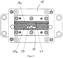
- FIG. 3 shows that the first contact surface 19 comprises a lower and upper region 19a, 19b.
- the lower and upper regions 19a, 19b are separated by a separating knife 21.
- a recess 23 is provided, which has the shape of a Euro hole (Eurolochmatrize).
- a sonotrode 25 is arranged at the second sealing bar 17 .
- the sonotrode is set in high-frequency oscillation by an ultrasonic generator 27.
- a second Contact surface 29 is formed as part of the sonotrode 25 ( FIG. 2 ).
- Also part of the sonotrode 25 is a punch 31, which punched out a Euro hole from a plastic bag.
- a separating knife counter edge 33 divides the second contact surface into an upper and a lower part 29a, 29b.
- first and second sealing bars 15,17 a plastic tube is pulled with a longitudinal seam perpendicular to the sealing bar.
- the plastic tube was prepared in advance on a forming shoulder and by a longitudinal sealing seam of a plastic film. If the plastic tube is in the correct position relative to the sealing bars 15, 17, the first sealing bar 15 is displaced along the support 13 into the sealing position.
- the Euroloch punch 31 punches out of the plastic tube a Euro hole.
- Ultrasonic punching of the suspension hole results in a clean cut at the edges and a complete removal of the stamped part.
- punching with ultrasound causes the cut edges to be welded.
- the pull-out forces of the Euro hole increase considerably compared to Euro holes, which are produced by methods according to the prior art.
- the sealing bars 15,17 are adjusted in the sealing position so that the Eurolochstanze 31 has a distance from the recess 23 of between 0 and 10 microns and preferably between 0 and 5 microns, so that the Euroloch punch 31, the first contact surface 19 on the one hand does not touch and on the other hand, the plastic film, even if it only has a thickness in the single-digit micron range, is completely penetrated by the punch 31.
- a safety circuit is provided which switches off the sonotrode immediately upon contact within fractions of a second.
- the plastic tube is ultrasonically sealed between the first and second contact surfaces 19, 29.
- the seal has a positive visual impression and Impurities in the area to be sealed are displaced from the sealing seam.
- separating knife counter edge 33 Since a separating knife counter edge 33 is integrated into the sonotrode 25, the sealing seam is also cut apart in the sealing position. Because the cut is made with ultrasound, the cut edge is sealed and free from fraying. This creates a bottom bag with a top seal and an upper bag with a bottom seal.
- the separating knife counter edge 33 enables the most material-gentle cutting possible with the separating knife 21.
- the bag production is accordingly fast and visually appealing by the ultrasound application. It leads to a strong seal and a Euro hole with high pull-out forces.
- the sealing device 11 may also be equipped with a stamped part remover.
- the stamped part remover is designed as a plunger 35, which is arranged in the recess 35.
- the plunger 35 is linearly displaceable relative to the recess 23 in the direction of displacement of the first sealing bar.
- the plunger 35 can thereby expel Euroloch punched parts from the recess 23 through the anvil 18 therethrough.
- a chamber is preferably provided for receiving the punched out Euro hole punched parts.
- the chamber is in communication with the channel in which the punch 31 is linearly guided.
- the plunger 35 moves out and moves the Euro hole punching part in the channel 37 in the punch 31 until the Euro hole punched part is pushed or pushed into the chamber ,
- the Euroloch punched parts do not have to be pushed out of the recess 23 during each sealing cycle, but it is also possible for several collected Euro hole punched parts to be pushed out of the recess 23 at the same time. From the chamber, the collected Euroloch stamped parts can be sucked into a foil waste container.
- the sealing device 11 makes it possible, by transferring the sealing bars into the sealing position, in one single step, to produce a top and bottom seal, to punch out a euro hole and to cut it apart two adjacent plastic bag, by contact surface, punching and separating knife or counter blade counter edge are integrated in a sonotrode.
- the cutting, sealing and punching is done very precisely because the cut edges are sealed. Furthermore, the ultrasonic welding is quick and reliable.
Landscapes
- Engineering & Computer Science (AREA)
- Mechanical Engineering (AREA)
- Lining Or Joining Of Plastics Or The Like (AREA)
- Package Closures (AREA)
Description
- Die Erfindung betrifft eine Siegelvorrichtung zum Verschweissen eines Kunststoffbeutels gemäss Oberbegriff des Anspruchs 1.
- Nach dem Stand der Technik werden Kunststoffbeutel mit einer definierten Aufhängungsöffnung zur Aufhängung an Verkaufsdisplays (sogenanntes Euroloch) mit einer Stanze hergestellt. Der Stanzvorgang wird nach einem thermischen Siegelvorgang vorgenommen, welcher die Kunststoffbeutel durch Verschweissen verschliesst. Dem Herstellverfahren ist es zu eigen, dass das Stanzteil nicht vollständig entfernbar ist und an einer Stelle der Aufhängungsöffnung mit dem Kunststoffbeutel verbunden bleibt. Würde das Stanzteil vollständig ausgestanzt werden, so würde es an dem Stanzwerkzeug haften bleiben und schwierig aus diesem zu entfernen sein. Verunreinigungen zwischen den zu verschliessenden Beutelteilen werden in der Siegelfläche eingeschweisst und ergeben zusammen mit dem nicht vollständig ausgestanzten Stanzteil ein unschönes Verpackungsäusseres.
- In der
GB 2470502 A - In der
EP 1 127 794 ist eine Ultraschallsiegelvorrichtung beschrieben, welche ein Horn mit einer länglichen flachen Siegelfläche und einen mit einer Wirkfläche versehenen Gegenbacken aufweist. Das Horn wird durch Konverter in Ultraschallschwingung versetzt. Ein Anschlag regelt den Abstand zwischen der Siegelfläche und der Wirkfläche. - In der
EP 1344 631 A1 ist ein Verfahren beschrieben, bei dem mehrere Kunststoffbeutel zu einem Block verbunden werden. Dazu wird ein stiftförmiger Sonotrodenfortsatz in den Stapel von Beuteln gedrückt und schweisst sich in den Stapel ein. Beim Herausziehen des stiftförmigen Fortsatzes wird ein zylindrischer Schweisskanal gebildet, wobei die Verschweissung die einzelnen Lagen zusammenhält. Durch den Schweisskanal sind die einzelnen Kunststoffbeutel zu einem Block verschweisst und aneinander gehalten. Entlang einer Perforationslinie lassen sich die einzelnen Kunststoffbeutel abreissen und vereinzeln. Die obersten Lagen von Kunststoffbeuteln werden durch zwei Spitzen zusätzlich verschweisst, welche an der Sonotrode ausgeformt sind. Ziel ist es möglichst leicht auftrennbare Schweissstellen zu erzeugen, welche dem Abreissen eines Kunststoffbeutels von dem Beutelblock nicht hinderlich sind. - In der
DE 10 2004 013 050 ist eine Ultraschallschweissvorrichtung offenbart, mit welcher Beutel verschweissbar sind, auch wenn deren Schweissnahtbereich kontaminiert ist. Die Schweissflächen und eine Formschneidkante zur Ausstanzung eines Eurolochs sind an dem Amboss angeordnet. Die Sonotrode weist an der dem Amboss zugewandten Seite keine Erhebungen, Vertiefungen oder Stanzen auf. - In der
EP 2 505 340 ist ein Folienschweissgerät zur Herstellung von Folienbeuteln offenbart. Das Gerät verfügt über eine Impulsheizeinrichtung, welche eine rasche Aufheizung auf 250 - 350 °C ermöglicht. Ein Eurolochprofil ermöglicht das Ausstanzen eines Eurolochs in dem Folienbeutel. - Auch in der
NL 1008645 - Die Aufgabe, die durch die vorliegenden Erfindung gelöst wird, besteht darin, das vorstehende Herstellverfahren zu vereinfachen und zu beschleunigen. Noch ein Ziel der Erfindung ist es das Erscheinungsbild von Aufhängungsöffnung und Siegelfläche bei Kunststoffbeuteln zu verbessern.
- Die Erfindung betrifft eine Siegelvorrichtung, bei der in der ersten oder zweiten Kontaktfläche eine Stanze integriert ist, welche das Ausstanzen einer Aufhängungsöffnung gleichzeitig mit dem Verschweissen des Kunststoffbeutels ermöglicht. Die Integration der Stanze ermöglicht es, dass in einem einzigen Arbeitsschritt der Kunststoffbeutel versiegelt wird und gleichzeitig eine Aufhängungsöffnung, beispielsweise ein Euroloch, in der Siegelnaht ausgestanzt wird. Dementsprechend rasch kann die Herstellung von Kunststoffbeuteln mit Euroloch vor sich gehen.
- Erfindungsgemäss wird die Aufgabe durch eine Siegelvorrichtung gemäß dem unabhängigen Anspruch 1 gelöst. Die Sonotrode wird durch das Einleiten von Ultraschallschwingungen, welche von einem Ultraschallgenerator erzeugt werden, in Resonanzschwingung versetzt. Dadurch kann mit der ersten und zweiten Kontaktfläche ultraschall-geschweisst werden. Neben der Beutelversiegelung mit Ultraschall wird gleichzeitig die Aufhängungsöffnung, bevorzugt ein Euroloch, aus der Versiegelung ausgestanzt. Die Schnittkante des Eurolochs wird durch das Ausstanzen mit Ultraschall versiegelt, wodurch die Ausreisskräfte des Eurolochs sehr hoch sind.
- Zweckmässigerweise sind in der geschlossenen Position zwischen der Stanze und der ersten Kontaktfläche ein Sicherheitsabstand vorgesehen ist. Die starke Materialabnutzung der Stanze im Falle einer Berührung mit harten Materialien ist durch den Sicherheitsabstand verhindert.
- Mit Vorteil beträgt der Sicherheitsabstand zwischen 0 und 10µm und bevorzugt zwischen 0 und 5 µm. Dieser Abstand ermöglicht, dass die Stanze den Kunststoffbeutel durchdringen kann, auch wenn dieser sehr dünn ist, und trotzdem die erste Kontaktfläche nicht berührt. Bei einer Berührung wird die Sonotrode in Sekundenbruchteilen abgeschaltet. Der Sicherheitsabstand wird bewusst so klein wie möglich gewählt, um auch Folien mit einer Dicke unter 5 µm stanzen zu können.
- Als vorteilhaft erweist es sich, wenn eine Sicherheitsschaltung vorgesehen ist, welche die Sonotrode deaktiviert, falls die Stanze die erste Kontaktfläche in der Siegelposition berührt. Die materialzerstörende Wirkung der Berührung der Sonotrode von anderen Werkzeugen ist daher zweifach verhindert.
- In einer weiteren besonders bevorzugten Ausführungsform sind am oberen Rand des ersten und zweiten Kontaktfläche ein Trennmesser bzw. eine Trennmesser-Gegenkante ausgebildet. Die Sonotrode bewirkt in der Siegelposition nicht nur das Versiegeln der Kunststoffbeutel und das Ausstanzen des Eurolochs, sondern schneidet den mit Siegelnähten versehenen Kunststoffschlauch in Kunststoffbeutel. Die Schnittkanten werden durch den Ultraschall verschweisst und sind deshalb weder scharfkantig noch ausgefranst.
- Vorteilhaft ist die Trennmesser-Gegenkante Teil der Sonotrode. Die Trennmesser-Gegenkante ermöglicht ein materialschonendes und exaktes Schneiden der Kunststoffbeutel. Sollte sich Trennmesser und Trennmesser-Gegenkante während des Betriebs berühren, so ist es denkbar dass die Sicherheitsschaltung die Sonotrode deaktiviert.
- Mit Vorteil sind die erste und zweite Kontaktflächen zwischen Trennmesser und oberen Kanten zur Ausbildung der Unterversiegelung des Kunststoffbeutels ausgebildet und die erste und zweite Kontaktflächen zwischen Trennmesser und unteren Kanten zur Ausbildung der Oberversiegelung des Kunststoffbeutels ausgebildet. Es werden zur Kunststoffbeutel-Herstellung daher nicht zwei Arbeitsschritte zur Herstellung der Unter- und Oberversiegelung benötigt. In einem einzigen Arbeitsschritt, welchen das Schliessen und Öffnen der Siegelbalken darstellt, werden eine Ober- und Unterversiegelung, ein Euroloch und ein Trennschnitt hergestellt.
- Zweckmässigerweise schwingt die Sonotrode mit einer Frequenz von 18 bis 21 kHz und bevorzugt von 19 bis 20 kHz . Dies Frequenz ist für Stanzen, Versiegeln und Schneiden mit Ultraschall gleichermassen geeignet.
- Gemäss einer besonders bevorzugten Ausführungsform der Erfindung ist in der ersten Kontaktfläche die Ausnehmung mit einem Stanzteil-Entferner vorgesehen. Die Ausnehmung dient als Gegenstück zu der Stanze in welche die Euroloch-Stanzteile von der Stanze gedrückt werden. Der Stanzteil-Entferner dient der kontrollierten Entfernung der Euroloch-Stanzteile aus der Ausnehmung. Die erfindungsgemässe Siegelvorrichtung ist daher immer frei von Euroloch-Stanzteilen. Dadurch arbeitet die Siegelvorrichtung besonders fehlerfrei, wodurch Produktionsunterbrechungen nahezu vermieden sind. Bei Siegelvorrichtungen des Stands der Technik verklemmen sich Euroloch-Stanzteile immer wieder oder kommen zwischen den Siegelbalken zu liegen, wo sie eine saubere Siegelnaht zu Nichte machen.
- Als besonders voreilhaft erweist es sich, wenn der der Stanzteil-Entferner ein Stössel ist, welcher relativ zur Ausnehmung in Verschieberrichtung des ersten Siegelbalkens linear verschiebbar ist. Hierdurch können Euroloch-Stanzteile kontrolliert aus der Ausnehmung gedrückt werden. Denkbar wäre es auch, dass der Stanzteil-Entferner eine Luftdüse ist, welche die Euroloch-Stanzteile aus der Ausnehmung bläst.
- Vorteilhaft ist in der Sonotrode eine Kammer zur Aufnahme des Stanzabfalls vorgesehen. Der Stössel kann die Euroloch-Stanzteile direkt in die Kammer schieben, in welcher sie zentral als Abfall gesammelt werden können und nirgends sonst den Siegelprozess behindern. Denkbar wäre es auch, dass der Stanzteil-Entferner in der Stanze angeordnet ist und die Euroloch-Stanzteile in eine Kammer im Bereich des Ambosses schiebt.
- Gemäss einem weiteren Ausführungsbeispiel der Erfindung steht die Kammer in Verbindung mit einem Kanal, welcher in der Stanze vorgesehen ist. Hierdurch kann der Stössel das Euroloch-Stanzteil in dem Kanal verschieben, bis es in die Kammergestossen ist.
- Bevorzugter Weise ist die Kammer absaugbar. Dies hat den Vorteil, dass die in der Kammer gesammelten Euroloch-Stanzteile in eine zentralen Abfallbehälter gesaugt werden können, spätestens dann, wenn die Kammer mit Euroloch-Stanzteilen gefüllt ist.
- Weitere Vorteile und Merkmale ergeben sich aus der nachfolgenden Beschreibung eines Ausführungsbeispiels der Erfindung unter Bezugnahme auf die schematischen Darstellungen. Es zeigen in nicht massstabsgetreuer Darstellung:
- Figur 1:
- Axonometrische Darstellung einer erfindungsgemässen Siegelvorrichtung mit zwei Siegelbalken als Sonotrode bzw. Amboss ausgebildet;
- Figur 2:
- eine Frontansicht der Sonotrode und
- Figur 3:
- eine Frontansicht des Amboss.
- Die
Figur 1 zeigt eine erfindungsgemässe Siegelvorrichtung, welche gesamthaft mit dem Bezugszeichen 11 bezeichnet ist. Die Siegelvorrichtung 11 umfasst einen Support 13, welcher in derFigur 1 als ein Schienensystem mit zwei parallelen Rohren gezeigt ist. An dem Support 13 sind ein erster und zweiter Siegelbalken 15,17 angeordnet. Bevorzugt ist der erste Siegelbalken 15 entlang des Supports 13 verschiebbar und der zweite Siegelbalken 17 ist unverschiebbar an dem Support 13 festgelegt. Der erste Siegelbalken 15 lässt sich aus einer Offenposition, in der ein längsverschweisster Kunststoffschlauch zwischen den beiden Siegelbalken 15,17 verschoben wird, in eine Siegelposition verschieben. Befindet sich der Kunststoffschlauch in der richtigen Längsposition, wird der erste Siegelbalken entlang des Schienensystems in die Siegelposition verschoben. - An dem ersten Siegelbalken 15 ist ein Amboss 18 mit einer ersten Kontaktfläche 19 angeordnet.
Figur 3 zeigt, dass die erste Kontaktfläche 19 einen unteren und oberen Bereich 19a,19b umfasst. Der untere und der obere Bereich 19a,19b werden durch ein Trennmesser 21 voneinander getrennt. In dem unteren Bereich 19b ist eine Ausnehmung 23 vorgesehen, welche die Gestalt eines Eurolochs besitzt (Eurolochmatrize). - An dem zweiten Siegelbalken 17 ist eine Sonotrode 25 angeordnet. Die Sonotrode wird durch einen Ultraschallgenerator 27 in hochfrequente Schwingung versetzt. Eine zweite Kontaktfläche 29 ist als Teil der Sonotrode 25 ausgebildet (
Figur 2 ). Ebenfalls Teil der Sonotrode 25 ist eine Stanze 31, welche ein Euroloch aus einem Kunststoffbeutel ausstanzt. Eine Trennmesser-Gegenkante 33 teilt die zweite Kontaktfläche in einen oberen und einen unteren Teil 29a,29b. - Zur Herstellung eines Kunststoffbeutels mit Unter- und Oberversiegelung, sowie mit einem Euroloch wird mit der erfindungsgemässen Siegelvorrichtung lediglich ein einziger Arbeitsschritt benötigt.
- Zwischen dem ersten und zweiten Siegelbalken 15,17 wird ein Kunststoffschlauch mit einer Längsnaht senkrecht zu den Siegelbalken hindurchgezogen. Der Kunststoffschlauch wurde vorab an einer Formschulter und durch eine Längssiegelnaht aus einer Kunststofffolie hergestellt. Befindet sich der Kunststoffschlauch relativ zu den Siegelbalken 15,17 in der richtigen Position, wird der erste Siegelbalken 15 entlang des Supports 13 in die Siegelposition verschoben.
- In der Siegelposition werden 3 Arbeitsschritte gleichzeitig vorgenommen. Zum einen stanzt die Euroloch-Stanze 31 aus dem Kunststoffschlauch ein Euroloch. Das Ausstanzen der Aufhängungsöffnung (Euroloch) mittels Ultraschall bewirkt einen sauberen Schnitt an den Kanten und eine vollständige Entfernung des Stanzteils. Das Ausstanzen mit Ultraschall bewirkt gleichzeitig, dass die Schnittkanten verschweisst werden. Neben dem positiven optischen Eindruck erhöhen sich die Ausreisskräfte des Eurolochs erheblich gegenüber Eurolöchern, welche mit Verfahren gemäss dem Stand der Technik hergestellt werden. Die Siegelbalken 15,17 sind in der Siegelposition so justiert, dass die Eurolochstanze 31 einen Abstand zur Ausnehmung 23 von zwischen 0 und 10 µm und bevorzugt zwischen 0 und 5 µm aufweist, damit die Euroloch-Stanze 31 die erste Kontaktfläche 19 einerseits nicht berührt und andererseits die Kunststofffolie, auch wenn diese nur eine Dicke im einstelligen µm-Bereich besitzt, von der Stanze 31 vollständig durchstossen wird. Um eine Berührung, welche zu sehr starken Abnutzung der Stanze 31 führen würde, noch zusätzlich zu verhindern, ist eine Sicherheitsschaltung vorgesehen, welche die Sonotrode bei Berührung sofort innerhalb von Sekundenbruchteilen abschaltet.
- Der Kunststoffschlauch wird zwischen der ersten und zweiten Kontaktfläche 19,29 ultraschallversiegelt. Die Versiegelung besitzt einen positiven optischen Eindruck und Verunreinigungen in dem zu versiegelnden Bereich werden aus der Siegelnaht verdrängt.
- Da in die Sonotrode 25 auch eine Trennmesser-Gegenkante 33 integriert ist, wird die Siegelnaht in der Siegelposition auch auseinander geschnitten. Da der Schnitt mit Ultraschall hergestellt wird, ist die Schnittkante versiegelt und frei von Ausfransungen. Dadurch entsteht ein unterer Beutel mit einer Oberversiegelung und ein oberer Beutel mit einer Unterversiegelung. Durch die Integration von Siegel-Kontaktfläche 29, Trennmesser-Gegenkante 33 und Euroloch-Stanze 31 werden 3 Arbeitsschritte zur Beutelproduktion in der Siegelposition ausgeführt. Die Trennmesser-Gegenkante 33 ermöglicht ein möglichst materialschonendes Schneiden mit dem Trennmesser 21. Die Beutelproduktion ist dementsprechend rasch und durch die Ultraschall-Anwendung optisch ansprechend. Sie führt zu einer starken Versiegelung und einem Euroloch mit hohen Ausreisskräften.
- Die Siegelvorrichtung 11 kann auch mit einem Stanzteil-Entferner ausgerüstet sein. Der Stanzteil-Entferner ist als ein Stössel 35 ausgebildet, welcher in der Ausnehmung 35 angeordnet ist. Der Stössel 35 ist relativ zur Ausnehmung 23 in Verschieberichtung des ersten Siegelbalkens linear verschiebbar. Der Stössel 35 kann dadurch Euroloch-Stanzteile aus der Ausnehmung 23 durch den Amboss 18 hindurch ausstossen. Bevorzugt ist in der Sonotrode 25 eine Kammer zur Aufnahme der ausgestanzten Euroloch-Stanzteile vorgesehen. Bevorzugt steht die Kammer in Verbindung mit dem Kanal, in welchem die Stanze 31 linear geführt ist. Nachdem die Stanze 31 das Euroloch-Stanzteil ausgestanzt hat und in die Ausnehmung 23 gedrückt hat, fährt der Stössel 35 aus und verschiebt das Euroloch-Stanzteil in den Kanal 37 in der Stanze 31, bis das Euroloch-Stanzteil in die Kammergedrückt bzw. gestossen ist. Die Euroloch-Stanzteile müssen nicht während jedem Siegeltakt aus der Ausnehmung 23 gestossen werden, sondern es können auch mehrere gesammelte Euroloch-Stanzteile gleichzeitig aus der Ausnehmung 23 gestossen werden. Aus der Kammer können die gesammelten Euroloch-Stanzteile in einen Folien Abfallbehälter abgesaugt werden.
- Die erfindungsgemässe Siegelvorrichtung 11 ermöglicht durch Überführen der Siegelbalken in die Siegelposition in einem einzigen Arbeitsschritt das Herstellen einer Ober und Unterversiegelung, das Ausstanzen eines Eurolochs und das Auseinanderschneiden zweier benachbarter Kunststoffbeutel, indem Kontaktfläche, Stanze und Trennmesser bzw. Trennmesser-Gegenkante in einer Sonotrode integriert sind. Das Trennen, Versiegeln und Stanzen erfolgt sehr exakt, weil die Schnittkanten versiegelt werden. Ferner ist das Ultraschallschweissen rasch und zuverlässig.
-
- 11
- Siegelvorrichtung
- 13
- Support
- 15
- Erster Siegelbalken
- 17
- Zweiter Siegelbalken
- 18
- Amboss
- 19,19a,19b
- Erste Kontaktfläche, unterer und oberer Bereich
- 21
- Trennmesser
- 23
- Ausnehmung
- 25
- Sonotrode
- 27
- Ultraschallgenerator
- 29,29a,29b
- Zweite Kontaktfläche, unterer und oberer Bereich
- 31
- Euroloch-Stanze
- 33
- Trennmesser-Gegenkante
- 35
- Stössel
Claims (15)
- Siegelvorrichtung (11) zum Verschweissen eines Kunststoffbeutels mit- einem ersten und zweiten Siegelbalken (15,17),- einem Support (13) an welchem die zwei Siegelbalken (15,17) gehalten sind und entlang welchem wenigstens der erste Siegelbalken (15) gegenüber dem zweiten Siegelbalken (17) zwischen einer Siegelposition und einer Offenposition verschiebbar ist,- einer ersten und zweiten Kontaktfläche (19,29), zwischen welchen der Kunststoffbeutel verschweissbar ist und- einer in der ersten oder zweiten Kontaktfläche (19,29) integrierten Stanze (31), welche das Ausstanzen einer Aufhängungsöffnung gleichzeitig mit dem Verschweissen des Kunststoffbeutels ermöglicht.dadurch gekennzeichnet,
dass die Stanze (31) Teil einer Sonotrode (25) ist und in der der Stanze (31) abgewandten Kontaktfläche (19,29) eine Ausnehmung (23) in Gestalt der Aufhängungsöffnung vorgesehen ist. - Siegelvorrichtung nach Anspruch 1, dadurch gekennzeichnet, dass die zweite Kontaktfläche (29), in welche die Stanze (31) integriert ist, Teil der Sonotrode (25) ist.
- Siegelvorrichtung nach einem der Ansprüche 1 oder 2, dadurch gekennzeichnet, dass in der geschlossenen Position zwischen der Stanze (31) und der ersten Kontaktfläche (19) ein Sicherheitsabstand vorgesehen ist.
- Siegelvorrichtung nach Anspruch 3, dadurch gekennzeichnet, dass der Sicherheitsabstand zwischen 0 und 10 µm und bevorzugt zwischen 0 und 5 µm beträgt.
- Siegelvorrichtung nach einem der Ansprüche 2 bis 4, dadurch gekennzeichnet, dass eine Sicherheitsschaltung vorgesehen ist, welche die Sonotrode (25) deaktiviert, falls die Stanze (31) die erste Kontaktfläche (19) in der Siegelposition berührt.
- Siegelvorrichtung nach einem der Ansprüche 1 bis 5, dadurch gekennzeichnet, dass am oberen Rand des ersten und zweiten Kontaktfläche (19,29) ein Trennmesser (21) bzw. eine Trennmesser-Gegenkante (33) ausgebildet sind.
- Siegelvorrichtung nach Anspruch 6, dadurch gekennzeichnet, dass die Trennmesser-Gegenkante (33) Teil der Sonotrode (25) ist.
- Siegelvorrichtung nach einem der Ansprüche 1 bis 7, dadurch gekennzeichnet, dass die erste und zweite Kontaktfläche (19,29) zwischen Trennmesser (31) und oberen Kanten zur Ausbildung der Unterversiegelung des Kunststoffbeutels ausgebildet sind.
- Siegelvorrichtung nach einem der Ansprüche 1 bis 8, dadurch gekennzeichnet, dass die erste und zweite Kontaktfläche (19,29) zwischen Trennmesser (31) und unteren Kanten zur Ausbildung der Oberversiegelung des Kunststoffbeutels ausgebildet sind.
- Siegelvorrichtung nach einem der Ansprüche 2 bis 9, dadurch gekennzeichnet, dass die Sonotrode (25) mit einer Frequenz von 18 bis 21 kHz und bevorzugt von 19 bis 20 kHz schwingt.
- Siegel vorrichtung nach einem der Ansprüche 1 bis 10, dadurch gekennzeichnet, dass in der ersten Kontaktfläche (19) die Ausnehmung (23) mit einem Stanzteil-Entferner (35) vorgesehen ist.
- Siegelvorrichtung nach Anspruch 11, dadurch gekennzeichnet, dass der Stanzteil-Entferner ein Stössel (35) ist, welcher relativ zur Ausnehmung (23) in Verschieberrichtung des ersten Siegelbalkens (15) linear verschiebbar ist.
- Siegelvorrichtung nach einem der Ansprüche 1 bis 12, dadurch gekennzeichnet, dass in der Sonotrode (25) eine Kammer zur Aufnahme des Stanzabfalls vorgesehen ist.
- Siegelvorrichtung nach Anspruch 13, dadurch gekennzeichnet, dass die Kammer in Verbindung mit einem Kanal (37) steht, welcher in der Stanze (31) vorgesehen ist.
- Siegelvorrichtung nach einem der Ansprüche 13 oder 14, dadurch gekennzeichnet, dass die Kammer absaugbar ist.
Applications Claiming Priority (1)
| Application Number | Priority Date | Filing Date | Title |
|---|---|---|---|
| CH00430/14A CH709393B1 (de) | 2014-03-21 | 2014-03-21 | Siegelvorrichtung. |
Publications (2)
| Publication Number | Publication Date |
|---|---|
| EP2921283A1 EP2921283A1 (de) | 2015-09-23 |
| EP2921283B1 true EP2921283B1 (de) | 2018-05-30 |
Family
ID=52807588
Family Applications (1)
| Application Number | Title | Priority Date | Filing Date |
|---|---|---|---|
| EP15160391.7A Active EP2921283B1 (de) | 2014-03-21 | 2015-03-23 | Siegelvorrichtung |
Country Status (2)
| Country | Link |
|---|---|
| EP (1) | EP2921283B1 (de) |
| CH (1) | CH709393B1 (de) |
Families Citing this family (2)
| Publication number | Priority date | Publication date | Assignee | Title |
|---|---|---|---|---|
| WO2017184202A1 (en) * | 2016-04-18 | 2017-10-26 | Edison Welding Institute, Inc. | Modular ultrasonic device for use in package sealing systems |
| CN107128543A (zh) * | 2017-05-25 | 2017-09-05 | 青岛瑞德神运机电设备有限公司 | 超声波封口装置 |
Family Cites Families (10)
| Publication number | Priority date | Publication date | Assignee | Title |
|---|---|---|---|---|
| NL1008645C2 (nl) * | 1998-03-19 | 1999-09-21 | Dameta V O F | Smeltlaswang voor het smeltlassen van een aantal lagen foliemateriaal, smeltlasinrichting voorzien van een smeltlasbek uit twee van dergelijke smeltlaswangen en verpakking afgesloten door de tussenkomst van een dergelijke smeltlasinrichting. |
| JP4147309B2 (ja) * | 1998-03-23 | 2008-09-10 | 四国化工機株式会社 | 超音波シール装置 |
| JP4603122B2 (ja) * | 2000-02-23 | 2010-12-22 | 四国化工機株式会社 | 超音波シール装置 |
| ES2213096T3 (es) * | 2001-03-12 | 2004-08-16 | TETRA LAVAL HOLDINGS & FINANCE SA | Dispositivo de obturacion transversal ultrasonica y metodo para obturar las paredes de un material de empaquetado relleno de un producto alimentario fluido. |
| DE10211680B4 (de) * | 2002-03-15 | 2006-08-31 | Huhtamaki Forchheim Zweigniederlassung Der Huhtamaki Deutschland Gmbh & Co. Kg | Verfahren zum Verbinden mehrerer Lagen aus Kunststoffolie |
| DE102004013050A1 (de) * | 2004-03-10 | 2005-09-29 | Herrmann Ultraschalltechnik Gmbh & Co. Kg | Ultraschallschweißvorrichtung |
| DE202008005727U1 (de) * | 2008-04-24 | 2009-06-04 | Hastamat Verpackungstechnik Gmbh | Verpackungsbeutel, Siegelbackenanordnung |
| GB2470502B (en) * | 2008-10-07 | 2011-03-09 | Cadbury Holdings Ltd | Packaging |
| DE102009002296A1 (de) * | 2009-04-09 | 2010-10-14 | Robert Bosch Gmbh | Vorrichtung und Verfahren zum Bearbeiten eines Packstoffs mittels Ultraschall |
| EP2505340A1 (de) * | 2011-04-01 | 2012-10-03 | ROPEX Industrie-Elektronik GmbH | Folienfügeeinrichtung, Folienbeutel und Verfahren zum Fügen von Folienbahnen |
-
2014
- 2014-03-21 CH CH00430/14A patent/CH709393B1/de unknown
-
2015
- 2015-03-23 EP EP15160391.7A patent/EP2921283B1/de active Active
Non-Patent Citations (1)
| Title |
|---|
| None * |
Also Published As
| Publication number | Publication date |
|---|---|
| CH709393A1 (de) | 2015-09-30 |
| CH709393B1 (de) | 2018-05-31 |
| EP2921283A1 (de) | 2015-09-23 |
Similar Documents
| Publication | Publication Date | Title |
|---|---|---|
| EP2812174B1 (de) | Verfahren und vorrichtung zur konfektionierung von schlauchbeuteln aus dünnen kunststofffolien mittels eines ultraschall-schweissverfahrens | |
| DE102010043090A1 (de) | Vorrichtung zum Trennen eines Packstoffs für eine Verpackung | |
| WO2018054695A1 (de) | Vorrichtung zum verbinden von zwei behälterteilen | |
| EP2800699B1 (de) | Verpackungsmaschine mit einer schneidstation | |
| EP2921283B1 (de) | Siegelvorrichtung | |
| EP2119629A1 (de) | Schlauchbeutelmaschine und Verfahren | |
| EP2505340A1 (de) | Folienfügeeinrichtung, Folienbeutel und Verfahren zum Fügen von Folienbahnen | |
| EP2106373B1 (de) | Beutel mit öffnungshilfe | |
| DE102009000240A1 (de) | Vorrichtung zum Schweißen und Trennen von Packstoffen | |
| EP3919215B1 (de) | Schweissvorrichtung sowie verfahren zum schweissen eines auslasselements an ein verpackungsmaterial | |
| DE102014101802A1 (de) | Verfahren und Vorrichtung zum Ultraschall-Siegeln und Trennen von Schlauchbeuteln | |
| EP1379373B1 (de) | Verfahren und vorrichtung zum formen von gegenständen aus einem materialstrang und zum vereinzeln der gegenstände | |
| WO2012107522A1 (de) | Verfahren zur herstellung einer quersiegelnaht sowie quersiegelvorrichtung | |
| EP1138603A1 (de) | Vorrichtung und Verfahren zum Verschweissen in Schlauchbeuteln | |
| DE10208997B4 (de) | Verfahren und Vorrichtung zum Stanzen von versiegelten becherartigen Behältern | |
| DE1479275B2 (de) | Verfahren und Vorrichtung zum Abtren nen von Abfallstucken beim Herstellen von Hohlkörpern aus thermoplastischem Kunststoff im Blasverfahren | |
| DE1186392B (de) | Maschine zum Herstellen gefuellter und verschlossener Beutel mit rechteckigem, standfestem Boden | |
| DE1479856B2 (de) | Verfahren und vorrichtung zum herstellen von aus schweissbarer kunststoffolie bestehenden beuteln mit anschweissteilen aus kunststoff | |
| DE19535511A1 (de) | Trennvorrichtung für Verpackungsmaterial | |
| EP3047962B1 (de) | Vorrichtung zum versiegeln einer verpackung oder eines verpackungsmaterials | |
| EP1538086A1 (de) | Vorrichtung zum Herstellen einer Beutelkette | |
| WO2023135280A1 (de) | Schweissnaht, verfahren und vorrichtung zum verbinden von kunststofffolien durch thermisches fügen sowie verwendung einer schlagpresse | |
| DE4236152A1 (de) | Verfahren und Vorrichtung zum Ausstanzen von Formkörpern | |
| EP4241946A2 (de) | Stanzwerkzeug | |
| DE102004029430A1 (de) | Vorrichtung zum Verschweißen und Durchtrennen eines Folienschlauches |
Legal Events
| Date | Code | Title | Description |
|---|---|---|---|
| PUAI | Public reference made under article 153(3) epc to a published international application that has entered the european phase |
Free format text: ORIGINAL CODE: 0009012 |
|
| AK | Designated contracting states |
Kind code of ref document: A1 Designated state(s): AL AT BE BG CH CY CZ DE DK EE ES FI FR GB GR HR HU IE IS IT LI LT LU LV MC MK MT NL NO PL PT RO RS SE SI SK SM TR |
|
| AX | Request for extension of the european patent |
Extension state: BA ME |
|
| 17P | Request for examination filed |
Effective date: 20160321 |
|
| RBV | Designated contracting states (corrected) |
Designated state(s): AL AT BE BG CH CY CZ DE DK EE ES FI FR GB GR HR HU IE IS IT LI LT LU LV MC MK MT NL NO PL PT RO RS SE SI SK SM TR |
|
| GRAP | Despatch of communication of intention to grant a patent |
Free format text: ORIGINAL CODE: EPIDOSNIGR1 |
|
| STAA | Information on the status of an ep patent application or granted ep patent |
Free format text: STATUS: GRANT OF PATENT IS INTENDED |
|
| RIC1 | Information provided on ipc code assigned before grant |
Ipc: B29L 31/00 20060101ALI20171123BHEP Ipc: B65B 51/22 20060101ALI20171123BHEP Ipc: B29C 65/08 20060101AFI20171123BHEP Ipc: B29C 65/74 20060101ALI20171123BHEP Ipc: B65D 75/56 20060101ALI20171123BHEP Ipc: B65B 61/16 20060101ALI20171123BHEP Ipc: B29C 65/00 20060101ALI20171123BHEP |
|
| INTG | Intention to grant announced |
Effective date: 20171220 |
|
| GRAS | Grant fee paid |
Free format text: ORIGINAL CODE: EPIDOSNIGR3 |
|
| GRAA | (expected) grant |
Free format text: ORIGINAL CODE: 0009210 |
|
| STAA | Information on the status of an ep patent application or granted ep patent |
Free format text: STATUS: THE PATENT HAS BEEN GRANTED |
|
| AK | Designated contracting states |
Kind code of ref document: B1 Designated state(s): AL AT BE BG CH CY CZ DE DK EE ES FI FR GB GR HR HU IE IS IT LI LT LU LV MC MK MT NL NO PL PT RO RS SE SI SK SM TR |
|
| RAP1 | Party data changed (applicant data changed or rights of an application transferred) |
Owner name: SCHIERLE, ROLAND |
|
| REG | Reference to a national code |
Ref country code: GB Ref legal event code: FG4D Free format text: NOT ENGLISH |
|
| RIN1 | Information on inventor provided before grant (corrected) |
Inventor name: SCHIERLE, ROLAND |
|
| REG | Reference to a national code |
Ref country code: CH Ref legal event code: EP |
|
| REG | Reference to a national code |
Ref country code: AT Ref legal event code: REF Ref document number: 1003166 Country of ref document: AT Kind code of ref document: T Effective date: 20180615 |
|
| REG | Reference to a national code |
Ref country code: IE Ref legal event code: FG4D Free format text: LANGUAGE OF EP DOCUMENT: GERMAN |
|
| REG | Reference to a national code |
Ref country code: DE Ref legal event code: R096 Ref document number: 502015004427 Country of ref document: DE |
|
| REG | Reference to a national code |
Ref country code: CH Ref legal event code: NV Representative=s name: RIEDERER HASLER AND PARTNER PATENTANWAELTE AG, CH |
|
| REG | Reference to a national code |
Ref country code: NL Ref legal event code: MP Effective date: 20180530 |
|
| REG | Reference to a national code |
Ref country code: LT Ref legal event code: MG4D |
|
| PG25 | Lapsed in a contracting state [announced via postgrant information from national office to epo] |
Ref country code: LT Free format text: LAPSE BECAUSE OF FAILURE TO SUBMIT A TRANSLATION OF THE DESCRIPTION OR TO PAY THE FEE WITHIN THE PRESCRIBED TIME-LIMIT Effective date: 20180530 Ref country code: CY Free format text: LAPSE BECAUSE OF FAILURE TO SUBMIT A TRANSLATION OF THE DESCRIPTION OR TO PAY THE FEE WITHIN THE PRESCRIBED TIME-LIMIT Effective date: 20180530 Ref country code: NO Free format text: LAPSE BECAUSE OF FAILURE TO SUBMIT A TRANSLATION OF THE DESCRIPTION OR TO PAY THE FEE WITHIN THE PRESCRIBED TIME-LIMIT Effective date: 20180830 Ref country code: SE Free format text: LAPSE BECAUSE OF FAILURE TO SUBMIT A TRANSLATION OF THE DESCRIPTION OR TO PAY THE FEE WITHIN THE PRESCRIBED TIME-LIMIT Effective date: 20180530 Ref country code: BG Free format text: LAPSE BECAUSE OF FAILURE TO SUBMIT A TRANSLATION OF THE DESCRIPTION OR TO PAY THE FEE WITHIN THE PRESCRIBED TIME-LIMIT Effective date: 20180830 Ref country code: FI Free format text: LAPSE BECAUSE OF FAILURE TO SUBMIT A TRANSLATION OF THE DESCRIPTION OR TO PAY THE FEE WITHIN THE PRESCRIBED TIME-LIMIT Effective date: 20180530 Ref country code: ES Free format text: LAPSE BECAUSE OF FAILURE TO SUBMIT A TRANSLATION OF THE DESCRIPTION OR TO PAY THE FEE WITHIN THE PRESCRIBED TIME-LIMIT Effective date: 20180530 |
|
| PG25 | Lapsed in a contracting state [announced via postgrant information from national office to epo] |
Ref country code: LV Free format text: LAPSE BECAUSE OF FAILURE TO SUBMIT A TRANSLATION OF THE DESCRIPTION OR TO PAY THE FEE WITHIN THE PRESCRIBED TIME-LIMIT Effective date: 20180530 Ref country code: HR Free format text: LAPSE BECAUSE OF FAILURE TO SUBMIT A TRANSLATION OF THE DESCRIPTION OR TO PAY THE FEE WITHIN THE PRESCRIBED TIME-LIMIT Effective date: 20180530 Ref country code: GR Free format text: LAPSE BECAUSE OF FAILURE TO SUBMIT A TRANSLATION OF THE DESCRIPTION OR TO PAY THE FEE WITHIN THE PRESCRIBED TIME-LIMIT Effective date: 20180831 Ref country code: RS Free format text: LAPSE BECAUSE OF FAILURE TO SUBMIT A TRANSLATION OF THE DESCRIPTION OR TO PAY THE FEE WITHIN THE PRESCRIBED TIME-LIMIT Effective date: 20180530 |
|
| PG25 | Lapsed in a contracting state [announced via postgrant information from national office to epo] |
Ref country code: NL Free format text: LAPSE BECAUSE OF FAILURE TO SUBMIT A TRANSLATION OF THE DESCRIPTION OR TO PAY THE FEE WITHIN THE PRESCRIBED TIME-LIMIT Effective date: 20180530 |
|
| PG25 | Lapsed in a contracting state [announced via postgrant information from national office to epo] |
Ref country code: DK Free format text: LAPSE BECAUSE OF FAILURE TO SUBMIT A TRANSLATION OF THE DESCRIPTION OR TO PAY THE FEE WITHIN THE PRESCRIBED TIME-LIMIT Effective date: 20180530 Ref country code: PL Free format text: LAPSE BECAUSE OF FAILURE TO SUBMIT A TRANSLATION OF THE DESCRIPTION OR TO PAY THE FEE WITHIN THE PRESCRIBED TIME-LIMIT Effective date: 20180530 Ref country code: EE Free format text: LAPSE BECAUSE OF FAILURE TO SUBMIT A TRANSLATION OF THE DESCRIPTION OR TO PAY THE FEE WITHIN THE PRESCRIBED TIME-LIMIT Effective date: 20180530 Ref country code: CZ Free format text: LAPSE BECAUSE OF FAILURE TO SUBMIT A TRANSLATION OF THE DESCRIPTION OR TO PAY THE FEE WITHIN THE PRESCRIBED TIME-LIMIT Effective date: 20180530 Ref country code: RO Free format text: LAPSE BECAUSE OF FAILURE TO SUBMIT A TRANSLATION OF THE DESCRIPTION OR TO PAY THE FEE WITHIN THE PRESCRIBED TIME-LIMIT Effective date: 20180530 Ref country code: SK Free format text: LAPSE BECAUSE OF FAILURE TO SUBMIT A TRANSLATION OF THE DESCRIPTION OR TO PAY THE FEE WITHIN THE PRESCRIBED TIME-LIMIT Effective date: 20180530 |
|
| PG25 | Lapsed in a contracting state [announced via postgrant information from national office to epo] |
Ref country code: SM Free format text: LAPSE BECAUSE OF FAILURE TO SUBMIT A TRANSLATION OF THE DESCRIPTION OR TO PAY THE FEE WITHIN THE PRESCRIBED TIME-LIMIT Effective date: 20180530 Ref country code: IT Free format text: LAPSE BECAUSE OF FAILURE TO SUBMIT A TRANSLATION OF THE DESCRIPTION OR TO PAY THE FEE WITHIN THE PRESCRIBED TIME-LIMIT Effective date: 20180530 |
|
| REG | Reference to a national code |
Ref country code: DE Ref legal event code: R097 Ref document number: 502015004427 Country of ref document: DE |
|
| PLBE | No opposition filed within time limit |
Free format text: ORIGINAL CODE: 0009261 |
|
| STAA | Information on the status of an ep patent application or granted ep patent |
Free format text: STATUS: NO OPPOSITION FILED WITHIN TIME LIMIT |
|
| 26N | No opposition filed |
Effective date: 20190301 |
|
| PG25 | Lapsed in a contracting state [announced via postgrant information from national office to epo] |
Ref country code: SI Free format text: LAPSE BECAUSE OF FAILURE TO SUBMIT A TRANSLATION OF THE DESCRIPTION OR TO PAY THE FEE WITHIN THE PRESCRIBED TIME-LIMIT Effective date: 20180530 |
|
| PG25 | Lapsed in a contracting state [announced via postgrant information from national office to epo] |
Ref country code: MC Free format text: LAPSE BECAUSE OF FAILURE TO SUBMIT A TRANSLATION OF THE DESCRIPTION OR TO PAY THE FEE WITHIN THE PRESCRIBED TIME-LIMIT Effective date: 20180530 |
|
| GBPC | Gb: european patent ceased through non-payment of renewal fee |
Effective date: 20190323 |
|
| PG25 | Lapsed in a contracting state [announced via postgrant information from national office to epo] |
Ref country code: LU Free format text: LAPSE BECAUSE OF NON-PAYMENT OF DUE FEES Effective date: 20190323 Ref country code: AL Free format text: LAPSE BECAUSE OF FAILURE TO SUBMIT A TRANSLATION OF THE DESCRIPTION OR TO PAY THE FEE WITHIN THE PRESCRIBED TIME-LIMIT Effective date: 20180530 |
|
| REG | Reference to a national code |
Ref country code: BE Ref legal event code: MM Effective date: 20190331 |
|
| PG25 | Lapsed in a contracting state [announced via postgrant information from national office to epo] |
Ref country code: IE Free format text: LAPSE BECAUSE OF NON-PAYMENT OF DUE FEES Effective date: 20190323 Ref country code: GB Free format text: LAPSE BECAUSE OF NON-PAYMENT OF DUE FEES Effective date: 20190323 |
|
| PG25 | Lapsed in a contracting state [announced via postgrant information from national office to epo] |
Ref country code: BE Free format text: LAPSE BECAUSE OF NON-PAYMENT OF DUE FEES Effective date: 20190331 Ref country code: FR Free format text: LAPSE BECAUSE OF NON-PAYMENT OF DUE FEES Effective date: 20190331 |
|
| PG25 | Lapsed in a contracting state [announced via postgrant information from national office to epo] |
Ref country code: TR Free format text: LAPSE BECAUSE OF FAILURE TO SUBMIT A TRANSLATION OF THE DESCRIPTION OR TO PAY THE FEE WITHIN THE PRESCRIBED TIME-LIMIT Effective date: 20180530 |
|
| PG25 | Lapsed in a contracting state [announced via postgrant information from national office to epo] |
Ref country code: MT Free format text: LAPSE BECAUSE OF FAILURE TO SUBMIT A TRANSLATION OF THE DESCRIPTION OR TO PAY THE FEE WITHIN THE PRESCRIBED TIME-LIMIT Effective date: 20180530 Ref country code: PT Free format text: LAPSE BECAUSE OF FAILURE TO SUBMIT A TRANSLATION OF THE DESCRIPTION OR TO PAY THE FEE WITHIN THE PRESCRIBED TIME-LIMIT Effective date: 20181001 |
|
| PG25 | Lapsed in a contracting state [announced via postgrant information from national office to epo] |
Ref country code: IS Free format text: LAPSE BECAUSE OF FAILURE TO SUBMIT A TRANSLATION OF THE DESCRIPTION OR TO PAY THE FEE WITHIN THE PRESCRIBED TIME-LIMIT Effective date: 20180930 |
|
| PG25 | Lapsed in a contracting state [announced via postgrant information from national office to epo] |
Ref country code: HU Free format text: LAPSE BECAUSE OF FAILURE TO SUBMIT A TRANSLATION OF THE DESCRIPTION OR TO PAY THE FEE WITHIN THE PRESCRIBED TIME-LIMIT; INVALID AB INITIO Effective date: 20150323 |
|
| PG25 | Lapsed in a contracting state [announced via postgrant information from national office to epo] |
Ref country code: MK Free format text: LAPSE BECAUSE OF FAILURE TO SUBMIT A TRANSLATION OF THE DESCRIPTION OR TO PAY THE FEE WITHIN THE PRESCRIBED TIME-LIMIT Effective date: 20180530 |
|
| REG | Reference to a national code |
Ref country code: DE Ref legal event code: R081 Ref document number: 502015004427 Country of ref document: DE Owner name: PAXMATIC AG, CH Free format text: FORMER OWNER: SCHIERLE, ROLAND, TRIN, CH |
|
| REG | Reference to a national code |
Ref country code: AT Ref legal event code: PC Ref document number: 1003166 Country of ref document: AT Kind code of ref document: T Owner name: PAXMATIC AG, CH Effective date: 20221108 |
|
| REG | Reference to a national code |
Ref country code: CH Ref legal event code: PK Free format text: BERICHTIGUNGEN |
|
| PGFP | Annual fee paid to national office [announced via postgrant information from national office to epo] |
Ref country code: AT Payment date: 20240321 Year of fee payment: 10 |
|
| PGFP | Annual fee paid to national office [announced via postgrant information from national office to epo] |
Ref country code: DE Payment date: 20240320 Year of fee payment: 10 |
|
| PGFP | Annual fee paid to national office [announced via postgrant information from national office to epo] |
Ref country code: CH Payment date: 20240401 Year of fee payment: 10 |