EP2919545B1 - Dispositif et procédé pour canal de commande enrichi (e-pdcch) - Google Patents
Dispositif et procédé pour canal de commande enrichi (e-pdcch) Download PDFInfo
- Publication number
- EP2919545B1 EP2919545B1 EP15163856.6A EP15163856A EP2919545B1 EP 2919545 B1 EP2919545 B1 EP 2919545B1 EP 15163856 A EP15163856 A EP 15163856A EP 2919545 B1 EP2919545 B1 EP 2919545B1
- Authority
- EP
- European Patent Office
- Prior art keywords
- pdcch
- wtru
- transmission
- cce
- subframe
- Prior art date
- Legal status (The legal status is an assumption and is not a legal conclusion. Google has not performed a legal analysis and makes no representation as to the accuracy of the status listed.)
- Active
Links
- 238000000034 method Methods 0.000 title claims description 142
- 230000005540 biological transmission Effects 0.000 claims description 297
- 238000013507 mapping Methods 0.000 claims description 74
- 230000011664 signaling Effects 0.000 claims description 42
- 239000010410 layer Substances 0.000 description 128
- 210000004027 cell Anatomy 0.000 description 66
- 230000002776 aggregation Effects 0.000 description 44
- 238000004220 aggregation Methods 0.000 description 44
- 230000006870 function Effects 0.000 description 30
- 238000004891 communication Methods 0.000 description 29
- 230000008569 process Effects 0.000 description 28
- 238000012545 processing Methods 0.000 description 25
- 238000005516 engineering process Methods 0.000 description 16
- 238000013468 resource allocation Methods 0.000 description 14
- 238000001514 detection method Methods 0.000 description 12
- 238000010586 diagram Methods 0.000 description 10
- 238000005259 measurement Methods 0.000 description 10
- 239000013598 vector Substances 0.000 description 10
- 230000009286 beneficial effect Effects 0.000 description 9
- 239000000969 carrier Substances 0.000 description 9
- 230000001419 dependent effect Effects 0.000 description 9
- 239000002356 single layer Substances 0.000 description 9
- 230000008901 benefit Effects 0.000 description 6
- 238000012544 monitoring process Methods 0.000 description 6
- 239000011159 matrix material Substances 0.000 description 5
- IUVCFHHAEHNCFT-INIZCTEOSA-N 2-[(1s)-1-[4-amino-3-(3-fluoro-4-propan-2-yloxyphenyl)pyrazolo[3,4-d]pyrimidin-1-yl]ethyl]-6-fluoro-3-(3-fluorophenyl)chromen-4-one Chemical compound C1=C(F)C(OC(C)C)=CC=C1C(C1=C(N)N=CN=C11)=NN1[C@@H](C)C1=C(C=2C=C(F)C=CC=2)C(=O)C2=CC(F)=CC=C2O1 IUVCFHHAEHNCFT-INIZCTEOSA-N 0.000 description 4
- 241000760358 Enodes Species 0.000 description 4
- 230000006978 adaptation Effects 0.000 description 4
- 230000002829 reductive effect Effects 0.000 description 4
- 101100411816 Arabidopsis thaliana RBG3 gene Proteins 0.000 description 3
- 101100411817 Arabidopsis thaliana RBG4 gene Proteins 0.000 description 3
- 101150077508 RBG1 gene Proteins 0.000 description 3
- 101150028167 RBG2 gene Proteins 0.000 description 3
- 238000013459 approach Methods 0.000 description 3
- 230000001413 cellular effect Effects 0.000 description 3
- 125000004122 cyclic group Chemical group 0.000 description 3
- PCHJSUWPFVWCPO-UHFFFAOYSA-N gold Chemical compound [Au] PCHJSUWPFVWCPO-UHFFFAOYSA-N 0.000 description 3
- 230000007774 longterm Effects 0.000 description 3
- 230000000873 masking effect Effects 0.000 description 3
- 230000002093 peripheral effect Effects 0.000 description 3
- 238000012935 Averaging Methods 0.000 description 2
- 101000741965 Homo sapiens Inactive tyrosine-protein kinase PRAG1 Proteins 0.000 description 2
- 102100038659 Inactive tyrosine-protein kinase PRAG1 Human genes 0.000 description 2
- 230000004913 activation Effects 0.000 description 2
- 238000001994 activation Methods 0.000 description 2
- 230000002411 adverse Effects 0.000 description 2
- 238000009826 distribution Methods 0.000 description 2
- 230000002708 enhancing effect Effects 0.000 description 2
- 230000002349 favourable effect Effects 0.000 description 2
- 239000010931 gold Substances 0.000 description 2
- 229910052737 gold Inorganic materials 0.000 description 2
- 230000006872 improvement Effects 0.000 description 2
- 229910001416 lithium ion Inorganic materials 0.000 description 2
- 238000007726 management method Methods 0.000 description 2
- 230000004048 modification Effects 0.000 description 2
- 238000012986 modification Methods 0.000 description 2
- QELJHCBNGDEXLD-UHFFFAOYSA-N nickel zinc Chemical compound [Ni].[Zn] QELJHCBNGDEXLD-UHFFFAOYSA-N 0.000 description 2
- 230000010363 phase shift Effects 0.000 description 2
- 230000009467 reduction Effects 0.000 description 2
- 230000004044 response Effects 0.000 description 2
- 230000002441 reversible effect Effects 0.000 description 2
- 101100219316 Arabidopsis thaliana CYP83B1 gene Proteins 0.000 description 1
- HBBGRARXTFLTSG-UHFFFAOYSA-N Lithium ion Chemical compound [Li+] HBBGRARXTFLTSG-UHFFFAOYSA-N 0.000 description 1
- 101100465000 Mus musculus Prag1 gene Proteins 0.000 description 1
- 210000004460 N cell Anatomy 0.000 description 1
- 241000700159 Rattus Species 0.000 description 1
- 101100145039 Saccharomyces cerevisiae (strain ATCC 204508 / S288c) RNT1 gene Proteins 0.000 description 1
- 238000004873 anchoring Methods 0.000 description 1
- 230000003139 buffering effect Effects 0.000 description 1
- OJIJEKBXJYRIBZ-UHFFFAOYSA-N cadmium nickel Chemical compound [Ni].[Cd] OJIJEKBXJYRIBZ-UHFFFAOYSA-N 0.000 description 1
- 230000000295 complement effect Effects 0.000 description 1
- 239000002131 composite material Substances 0.000 description 1
- 238000004590 computer program Methods 0.000 description 1
- 230000001351 cycling effect Effects 0.000 description 1
- 230000009849 deactivation Effects 0.000 description 1
- 230000003247 decreasing effect Effects 0.000 description 1
- 238000013461 design Methods 0.000 description 1
- 230000004069 differentiation Effects 0.000 description 1
- 239000002355 dual-layer Substances 0.000 description 1
- 230000000694 effects Effects 0.000 description 1
- 238000005562 fading Methods 0.000 description 1
- 238000009472 formulation Methods 0.000 description 1
- 239000000446 fuel Substances 0.000 description 1
- 238000007429 general method Methods 0.000 description 1
- 239000004973 liquid crystal related substance Substances 0.000 description 1
- 230000005055 memory storage Effects 0.000 description 1
- 229910052987 metal hydride Inorganic materials 0.000 description 1
- 239000000203 mixture Substances 0.000 description 1
- 238000010295 mobile communication Methods 0.000 description 1
- 229910052759 nickel Inorganic materials 0.000 description 1
- PXHVJJICTQNCMI-UHFFFAOYSA-N nickel Substances [Ni] PXHVJJICTQNCMI-UHFFFAOYSA-N 0.000 description 1
- -1 nickel metal hydride Chemical class 0.000 description 1
- 230000003287 optical effect Effects 0.000 description 1
- 230000008520 organization Effects 0.000 description 1
- 239000004065 semiconductor Substances 0.000 description 1
- 238000001228 spectrum Methods 0.000 description 1
- 239000013589 supplement Substances 0.000 description 1
Images


Classifications
-
- H—ELECTRICITY
- H04—ELECTRIC COMMUNICATION TECHNIQUE
- H04L—TRANSMISSION OF DIGITAL INFORMATION, e.g. TELEGRAPHIC COMMUNICATION
- H04L5/00—Arrangements affording multiple use of the transmission path
- H04L5/0001—Arrangements for dividing the transmission path
- H04L5/0003—Two-dimensional division
- H04L5/0005—Time-frequency
- H04L5/0007—Time-frequency the frequencies being orthogonal, e.g. OFDM(A), DMT
- H04L5/001—Time-frequency the frequencies being orthogonal, e.g. OFDM(A), DMT the frequencies being arranged in component carriers
-
- H—ELECTRICITY
- H04—ELECTRIC COMMUNICATION TECHNIQUE
- H04B—TRANSMISSION
- H04B7/00—Radio transmission systems, i.e. using radiation field
- H04B7/02—Diversity systems; Multi-antenna system, i.e. transmission or reception using multiple antennas
- H04B7/04—Diversity systems; Multi-antenna system, i.e. transmission or reception using multiple antennas using two or more spaced independent antennas
-
- H—ELECTRICITY
- H04—ELECTRIC COMMUNICATION TECHNIQUE
- H04L—TRANSMISSION OF DIGITAL INFORMATION, e.g. TELEGRAPHIC COMMUNICATION
- H04L25/00—Baseband systems
- H04L25/02—Details ; arrangements for supplying electrical power along data transmission lines
- H04L25/0202—Channel estimation
- H04L25/0224—Channel estimation using sounding signals
-
- H—ELECTRICITY
- H04—ELECTRIC COMMUNICATION TECHNIQUE
- H04L—TRANSMISSION OF DIGITAL INFORMATION, e.g. TELEGRAPHIC COMMUNICATION
- H04L5/00—Arrangements affording multiple use of the transmission path
- H04L5/003—Arrangements for allocating sub-channels of the transmission path
- H04L5/0048—Allocation of pilot signals, i.e. of signals known to the receiver
-
- H—ELECTRICITY
- H04—ELECTRIC COMMUNICATION TECHNIQUE
- H04W—WIRELESS COMMUNICATION NETWORKS
- H04W72/00—Local resource management
- H04W72/20—Control channels or signalling for resource management
-
- H—ELECTRICITY
- H04—ELECTRIC COMMUNICATION TECHNIQUE
- H04L—TRANSMISSION OF DIGITAL INFORMATION, e.g. TELEGRAPHIC COMMUNICATION
- H04L5/00—Arrangements affording multiple use of the transmission path
- H04L5/003—Arrangements for allocating sub-channels of the transmission path
- H04L5/0053—Allocation of signaling, i.e. of overhead other than pilot signals
-
- H—ELECTRICITY
- H04—ELECTRIC COMMUNICATION TECHNIQUE
- H04L—TRANSMISSION OF DIGITAL INFORMATION, e.g. TELEGRAPHIC COMMUNICATION
- H04L5/00—Arrangements affording multiple use of the transmission path
- H04L5/0091—Signaling for the administration of the divided path
- H04L5/0092—Indication of how the channel is divided
-
- H—ELECTRICITY
- H04—ELECTRIC COMMUNICATION TECHNIQUE
- H04L—TRANSMISSION OF DIGITAL INFORMATION, e.g. TELEGRAPHIC COMMUNICATION
- H04L5/00—Arrangements affording multiple use of the transmission path
- H04L5/0091—Signaling for the administration of the divided path
- H04L5/0094—Indication of how sub-channels of the path are allocated
Definitions
- the 3 rd Generation Partnership (3GPP) Long Term Evolution (LTE) Advanced protocol is a 4 th Generation (4G) wireless communication standard.
- LTE Advanced standard is constantly evolving in an attempt to provide enhanced services and capabilities for users.
- features such as worldwide functionality and roaming, compatibility of services, interworking with other radio access systems, and enhanced peak data rates to support advanced services and applications (e.g., 100 Mbit/s for high and 1 Gbit/s for low mobility) are goals for the networks implementing LTE Advanced.
- the details of mobility and radio control that allow for such functionality are to be designed and specified.
- WO 2010/053984 A2 discloses a mobile station receiving downlink control structure in a first carrier, where the downlik control structure indicates that control information for the mobile stationis on a second different, carrier.
- WO2010/131929 A2 discloses an apparatus and method for monitoring a control channel in a multi-carrier system.
- a method for a wireless transmit/receive unit (WTRU) to receive an enhanced physical downlink control channel (E-PDCCH) is disclosed.
- a WTRU may determine whether to attempt to decode the E-PDCCH in an identified subframe on an identified component carrier.
- the WTRU determine a plurality of resource elements (REs) in the identified subframe on the identified component carrier that are associated with an E-PDCCH region of the identified subframe.
- the WTRU may further determine at least one E-PDCCH candidate in the E-PDCCH region of the identified component carrier.
- the at least one E-PDCCH candidate may include a subset of the plurality of REs in the E-PDCCH region.
- the WTRU may attempt to process the E-PDCCH candidate.
- Attempting to process the E-PDCCH candidate may include performing spatial demultiplexing by determining at least one antenna port from which the WTRU attempts to decode the E-PDCCH candidate. Spatial demultiplexing may be performed based on at least one received user equipment (UE)-specific reference signal.
- the WTRU may determine the at least one E-PDCCH candidate in the E-PDCCH region is based on a location of at least one enhanced control channel element (E-CCE) in the E-PDCCH region.
- E-CCE enhanced control channel element
- Processing the E-PDCCH candidate may include demodulating a plurality of modulation symbols from the E-PDCCH candidate based on an assumed power ratio between the E-PDCCH and at least one received UE-specific reference signal for an antenna port that corresponds to the E-PDCCH candidate.
- the WTRU may determine the at least one E-PDCCH candidate in the E-PDCCH region of the identified component carrier based on an E-PDCCH parameter.
- the E-PDCCH parameter may be a determined transmission characteristic of the E-PDCCH.
- the E-PDCCH parameter may include at least one of an identity of at least one antenna port over which the E-PDCCH is received, a characteristic of the at least one antenna port over which the E-PDCCH is received, or a total number of antenna ports over which the E-PDCCH is received.
- the E-PDCCH candidate may include a plurality of E-CCEs.
- the plurality of E-CCEs may be received over multiple antenna ports.
- the WTRU may attempt to process the E-PDCCH candidate based on information received in a supporting physical downlink control channel (PDCCH).
- the WTRU may receive a physical downlink shared channel (PDSCH) based on information from the E-PDCCH.
- PDSCH physical downlink shared channel
- the WTRU may implicitly determine a transmission characteristic of the PDSCH based on a transmission characteristic of the E-PDCCH.
- a WTRU may receive an E-PDCCH by determining at least one antenna port associated with an E-PDCCH region.
- the WTRU may determine an E-PDCCH candidate located in the E-PDCCH region based on the at least one antenna port.
- the WTRU may attempt to process the E-PDCCH candidate based on at least one received precoded reference signal associated with the at least one antenna port.
- the at least one received precoded reference signal may be precoded with the same precoding weights as those used for the E-PDCCH candidate.
- An E-PDCCH may be associated with multiple antenna ports and the WTRU may attempt to process the E-PDCCH candidate based on a precoding relationship between the multiple antenna ports.
- the E-PDCCH region may be located outside of a legacy control region for a legacy physical downlink control channel (PDCCH).
- An E-PDCCH may be associated with multiple antenna ports and a WTRU may attempt to process the E-PDCCH by using a first precoded reference signal associated with a first antenna port to process a first portion of the E-PDCCH candidate and a second precoded reference signal associated with a second antenna port to process a second portion of the E-PDCCH candidate.
- the first precoded reference symbol may be associated with a first subset of resource elements (REs) in the E-PDCCH region and the second precoded reference symbol may be associated with a second subset of REs in the PDCCH region.
- REs resource elements
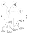
- FIG. 1A is a diagram of an example communications system 100 in which one or more disclosed embodiments may be implemented.
- the communications system 100 may be a multiple access system that provides content, such as voice, data, video, messaging, broadcast, etc., to multiple wireless users.
- the communications system 100 may enable multiple wireless users to access such content through the sharing of system resources, including wireless bandwidth.
- the communications systems 100 may employ one or more channel access methods, such as code division multiple access (CDMA), time division multiple access (TDMA), frequency division multiple access (FDMA), orthogonal FDMA (OFDMA), single-carrier FDMA (SC-FDMA), and the like.
- CDMA code division multiple access
- TDMA time division multiple access
- FDMA frequency division multiple access
- OFDMA orthogonal FDMA
- SC-FDMA single-carrier FDMA
- the communications system 100 may include wireless transmit/receive units (WTRUs) 102a, 102b, 102c, 102d, a radio access network (RAN) 104, a core network 106, a public switched telephone network (PSTN) 108, the Internet 110, and other networks 112, though it will be appreciated that the disclosed embodiments contemplate any number of WTRUs, base stations, networks, and/or network elements.
- WTRUs 102a, 102b, 102c, 102d may be any type of device configured to operate and/or communicate in a wireless environment.
- the WTRUs 102a, 102b, 102c, 102d may be configured to transmit and/or receive wireless signals and may include user equipment (UE), a mobile station, a fixed or mobile subscriber unit, a pager, a cellular telephone, a personal digital assistant (PDA), a smartphone, a laptop, a netbook, a personal computer, a wireless sensor, consumer electronics, and the like.
- UE user equipment
- PDA personal digital assistant
- smartphone a laptop
- netbook a personal computer
- a wireless sensor consumer electronics, and the like.
- the communications systems 100 may also include a base station 114a and a base station 114b.
- Each of the base stations 114a, 114b may be any type of device configured to wirelessly interface with at least one of the WTRUs 102a, 102b, 102c, 102d to facilitate access to one or more communication networks, such as the core network 106, the Internet 110, and/or the networks 112.
- the base stations 114a, 114b may be a base transceiver station (BTS), a Node-B, an eNode B, a Home Node B, a Home eNode B, a site controller, an access point (AP), a wireless router, and the like. While the base stations 114a, 114b are each depicted as a single element, it will be appreciated that the base stations 114a, 114b may include any number of interconnected base stations and/or network elements.
- the base station 114a may be part of the RAN 104, which may also include other base stations and/or network elements (not shown), such as a base station controller (BSC), a radio network controller (RNC), relay nodes, etc.
- BSC base station controller
- RNC radio network controller
- the base station 114a and/or the base station 114b may be configured to transmit and/or receive wireless signals within a particular geographic region, which may be referred to as a cell (not shown).
- the cell may further be divided into cell sectors.
- the cell associated with the base station 114a may be divided into three sectors.
- the base station 114a may include three transceivers, i.e., one for each sector of the cell.
- the base station 114a may employ multiple-input multiple output (MIMO) technology and, therefore, may utilize multiple transceivers for each sector of the cell.
- MIMO multiple-input multiple output
- the base stations 114a, 114b may communicate with one or more of the WTRUs 102a, 102b, 102c, 102d over an air interface 116, which may be any suitable wireless communication link (e.g ., radio frequency (RF), microwave, infrared (IR), ultraviolet (UV), visible light, etc .).
- the air interface 116 may be established using any suitable radio access technology (RAT).
- RAT radio access technology
- the communications system 100 may be a multiple access system and may employ one or more channel access schemes, such as CDMA, TDMA, FDMA, OFDMA, SC-FDMA, and the like.
- the base station 114a in the RAN 104 and the WTRUs 102a, 102b, 102c may implement a radio technology such as Universal Mobile Telecommunications System (UMTS) Terrestrial Radio Access (UTRA), which may establish the air interface 116 using wideband CDMA (WCDMA).
- WCDMA may include communication protocols such as High-Speed Packet Access (HSPA) and/or Evolved HSPA (HSPA+).
- HSPA may include High-Speed Downlink Packet Access (HSDPA) and/or High-Speed Uplink Packet Access (HSUPA).
- the base station 114a and the WTRUs 102a, 102b, 102c may implement a radio technology such as Evolved UMTS Terrestrial Radio Access (E-UTRA), which may establish the air interface 116 using Long Term Evolution (LTE) and/or LTE-Advanced (LTE-A).
- E-UTRA Evolved UMTS Terrestrial Radio Access
- LTE Long Term Evolution
- LTE-A LTE-Advanced
- the base station 114a and the WTRUs 102a, 102b, 102c may implement radio technologies such as IEEE 802.16 (i.e., Worldwide Interoperability for Microwave Access (WiMAX)), CDMA2000, CDMA2000 1X, CDMA2000 EV-DO, Interim Standard 2000 (IS-2000), Interim Standard 95 (IS-95), Interim Standard 856 (IS-856), Global System for Mobile communications (GSM), Enhanced Data rates for GSM Evolution (EDGE), GSM EDGE (GERAN), and the like.
- IEEE 802.16 i.e., Worldwide Interoperability for Microwave Access (WiMAX)
- CDMA2000, CDMA2000 1X, CDMA2000 EV-DO Code Division Multiple Access 2000
- IS-95 Interim Standard 95
- IS-856 Interim Standard 856
- GSM Global System for Mobile communications
- GSM Global System for Mobile communications
- EDGE Enhanced Data rates for GSM Evolution
- GERAN GSM EDGERAN
- the base station 114b in FIG. 1A may be a wireless router, Home Node B, Home eNode B, or access point, for example, and may utilize any suitable RAT for facilitating wireless connectivity in a localized area, such as a place of business, a home, a vehicle, a campus, and the like.
- the base station 114b and the WTRUs 102c, 102d may implement a radio technology such as IEEE 802.11 to establish a wireless local area network (WLAN).
- the base station 114b and the WTRUs 102c, 102d may implement a radio technology such as IEEE 802.15 to establish a wireless personal area network (WPAN).
- WLAN wireless local area network
- WPAN wireless personal area network
- the base station 114b and the WTRUs 102c, 102d may utilize a cellular-based RAT (e.g., WCDMA, CDMA2000, GSM, LTE, LTE-A, etc .) to establish a picocell or femtocell.
- a cellular-based RAT e.g., WCDMA, CDMA2000, GSM, LTE, LTE-A, etc .
- the base station 114b may have a direct connection to the Internet 110.
- the base station 114b may not be required to access the Internet 110 via the core network 106.
- the RAN 104 may be in communication with the core network 106, which may be any type of network configured to provide voice, data, applications, and/or voice over internet protocol (VoIP) services to one or more of the WTRUs 102a, 102b, 102c, 102d.
- the core network 106 may provide call control, billing services, mobile location-based services, pre-paid calling, Internet connectivity, video distribution, etc., and/or perform high-level security functions, such as user authentication.
- the RAN 104 and/or the core network 106 may be in direct or indirect communication with other RANs that employ the same RAT as the RAN 104 or a different RAT.
- the core network 106 may also be in communication with another RAN (not shown) employing a GSM radio technology.
- the core network 106 may also serve as a gateway for the WTRUs 102a, 102b, 102c, 102d to access the PSTN 108, the Internet 110, and/or other networks 112.
- the PSTN 108 may include circuit-switched telephone networks that provide plain old telephone service (POTS).
- POTS plain old telephone service
- the Internet 110 may include a global system of interconnected computer networks and devices that use common communication protocols, such as the transmission control protocol (TCP), user datagram protocol (UDP) and the internet protocol (IP) in the TCP/IP internet protocol suite.
- the networks 112 may include wired or wireless communications networks owned and/or operated by other service providers.
- the networks 112 may include another core network connected to one or more RANs, which may employ the same RAT as the RAN 104 or a different RAT.
- the WTRUs 102a, 102b, 102c, 102d in the communications system 100 may include multi-mode capabilities, i.e., the WTRUs 102a, 102b, 102c, 102d may include multiple transceivers for communicating with different wireless networks over different wireless links.
- the WTRU 102c shown in FIG. 1A may be configured to communicate with the base station 114a, which may employ a cellular-based radio technology, and with the base station 114b, which may employ an IEEE 802 radio technology.
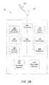
- FIG. 1B is a system diagram of an example WTRU 102.
- the WTRU 102 may include a processor 118, a transceiver 120, a transmit/receive element 122, a speaker/microphone 124, a keypad 126, a display/touchpad 128, non-removable memory 130, removable memory 132, a power source 134, a global positioning system (GPS) chipset 136, and other peripherals 138.
- GPS global positioning system
- the processor 118 may be a general purpose processor, a special purpose processor, a conventional processor, a digital signal processor (DSP), a plurality of microprocessors, one or more microprocessors in association with a DSP core, a controller, a microcontroller, Application Specific Integrated Circuits (ASICs), Field Programmable Gate Array (FPGAs) circuits, any other type of integrated circuit (IC), a state machine, and the like.
- the processor 118 may perform signal coding, data processing, power control, input/output processing, and/or any other functionality that enables the WTRU 102 to operate in a wireless environment.
- the processor 118 may be coupled to the transceiver 120, which may be coupled to the transmit/receive element 122. While FIG. 1B depicts the processor 118 and the transceiver 120 as separate components, it will be appreciated that the processor 118 and the transceiver 120 may be integrated together in an electronic package or chip.
- the transmit/receive element 122 may be configured to transmit signals to, or receive signals from, a base station (e.g. , the base station 114a) over the air interface 116.
- the transmit/receive element 122 may be an antenna configured to transmit and/or receive RF signals.
- the transmit/receive element 122 may be an emitter/detector configured to transmit and/or receive IR, UV, or visible light signals, for example.
- the transmit/receive element 122 may be configured to transmit and receive both RF and light signals. It will be appreciated that the transmit/receive element 122 may be configured to transmit and/or receive any combination of wireless signals.
- the WTRU 102 may include any number of transmit/receive elements 122. More specifically, the WTRU 102 may employ MIMO technology. Thus, in one example, the WTRU 102 may include two or more transmit/receive elements 122 (e.g., multiple antennas) for transmitting and receiving wireless signals over the air interface 116.
- the transceiver 120 may be configured to modulate the signals that are to be transmitted by the transmit/receive element 122 and to demodulate the signals that are received by the transmit/receive element 122.
- the WTRU 102 may have multi-mode capabilities.
- the transceiver 120 may include multiple transceivers for enabling the WTRU 102 to communicate via multiple RATs, such as UTRA and IEEE 802.11, for example.
- the processor 118 of the WTRU 102 may be coupled to, and may receive user input data from, the speaker/microphone 124, the keypad 126, and/or the display/touchpad 128 (e.g., a liquid crystal display (LCD) display unit or organic light-emitting diode (OLED) display unit).
- the processor 118 may also output user data to the speaker/microphone 124, the keypad 126, and/or the display/touchpad 128.
- the processor 118 may access information from, and store data in, any type of suitable memory, such as the non-removable memory 130 and/or the removable memory 132.
- the non-removable memory 130 may include random-access memory (RAM), read-only memory (ROM), a hard disk, or any other type of memory storage device.
- the removable memory 132 may include a subscriber identity module (SIM) card, a memory stick, a secure digital (SD) memory card, and the like.
- SIM subscriber identity module
- SD secure digital
- the processor 118 may access information from, and store data in, memory that is not physically located on the WTRU 102, such as on a server or a home computer (not shown).
- the processor 118 may receive power from the power source 134, and may be configured to distribute and/or control the power to the other components in the WTRU 102.
- the power source 134 may be any suitable device for powering the WTRU 102.
- the power source 134 may include one or more dry cell batteries (e . g ., nickel-cadmium (NiCd), nickel-zinc (NiZn), nickel metal hydride (NiMH), lithium-ion (Li-ion), etc .), solar cells, fuel cells, and the like.
- the processor 118 may also be coupled to the GPS chipset 136, which may be configured to provide location information (e.g. , longitude and latitude) regarding the current location of the WTRU 102.
- location information e.g. , longitude and latitude
- the WTRU 102 may receive location information over the air interface 116 from a base station (e.g. , base stations 114a, 114b) and/or determine its location based on the timing of the signals being received from two or more nearby base stations. It will be appreciated that the WTRU 102 may acquire location information by way of any suitable location-determination method.
- the processor 118 may further be coupled to other peripherals 138, which may include one or more software and/or hardware modules that provide additional features, functionality and/or wired or wireless connectivity.
- the peripherals 138 may include an accelerometer, an e-compass, a satellite transceiver, a digital camera (for photographs or video), a universal serial bus (USB) port, a vibration device, a television transceiver, a hands free headset, a Bluetooth® module, a frequency modulated (FM) radio unit, a digital music player, a media player, a video game player module, an Internet browser, and the like.
- the peripherals 138 may include an accelerometer, an e-compass, a satellite transceiver, a digital camera (for photographs or video), a universal serial bus (USB) port, a vibration device, a television transceiver, a hands free headset, a Bluetooth® module, a frequency modulated (FM) radio unit, a digital music player, a media player, a video game player
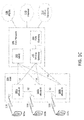
- FIG. 1C is a system diagram of the RAN 104 and the core network 106 according to an example.
- the RAN 104 may employ an E-UTRA radio technology to communicate with the WTRUs 102a, 102b, 102c over the air interface 116.
- the RAN 104 may also be in communication with the core network 106.
- the RAN 104 may include eNode-Bs 140a, 140b, 140c, though it will be appreciated that the RAN 104 may include any number of eNode-Bs .
- the eNode-Bs 140a, 140b, 140c may each include one or more transceivers for communicating with the WTRUs 102a, 102b, 102c over the air interface 116.
- the eNode-Bs 140a, 140b, 140c may implement MIMO technology.
- the eNode-B 140a for example, may use multiple antennas to transmit wireless signals to, and receive wireless signals from, the WTRU 102a.
- Each of the eNode-Bs 140a, 140b, 140c may be associated with a particular cell (not shown) and may be configured to handle radio resource management decisions, handover decisions, scheduling of users in the uplink and/or downlink, and the like. As shown in FIG. 1C , the eNode-Bs 140a, 140b, 140c may communicate with one another over an X2 interface.
- the core network 106 shown in FIG. 1C may include a mobility management gateway (MME) 142, a serving gateway 144, and a packet data network (PDN) gateway 146. While each of the foregoing elements are depicted as part of the core network 106, it will be appreciated that any one of these elements may be owned and/or operated by an entity other than the core network operator.
- MME mobility management gateway
- PDN packet data network
- the MME 142 may be connected to each of the eNode-Bs 142a, 142b, 142c in the RAN 104 via an S1 interface and may serve as a control node.
- the MME 142 may be responsible for authenticating users of the WTRUs 102a, 102b, 102c, bearer activation/deactivation, selecting a particular serving gateway during an initial attach of the WTRUs 102a, 102b, 102c, and the like.
- the MME 142 may also provide a control plane function for switching between the RAN 104 and other RANs (not shown) that employ other radio technologies, such as GSM or WCDMA.
- the serving gateway 144 may be connected to each of the eNode Bs 140a, 140b, 140c in the RAN 104 via the S1 interface.
- the serving gateway 144 may generally route and forward user data packets to/from the WTRUs 102a, 102b, 102c.
- the serving gateway 144 may also perform other functions, such as anchoring user planes during inter-eNode B handovers, triggering paging when downlink data is available for the WTRUs 102a, 102b, 102c, managing and storing contexts of the WTRUs 102a, 102b, 102c, and the like.
- the serving gateway 144 may also be connected to the PDN gateway 146, which may provide the WTRUs 102a, 102b, 102c with access to packet-switched networks, such as the Internet 110, to facilitate communications between the WTRUs 102a, 102b, 102c and IP-enabled devices.
- the PDN gateway 146 may provide the WTRUs 102a, 102b, 102c with access to packet-switched networks, such as the Internet 110, to facilitate communications between the WTRUs 102a, 102b, 102c and IP-enabled devices.
- the core network 106 may facilitate communications with other networks.
- the core network 106 may provide the WTRUs 102a, 102b, 102c with access to circuit-switched networks, such as the PSTN 108, to facilitate communications between the WTRUs 102a, 102b, 102c and traditional land-line communications devices.
- the core network 106 may include, or may communicate with, an IP gateway (e.g ., an IP multimedia subsystem (IMS) server) that serves as an interface between the core network 106 and the PSTN 108.
- IMS IP multimedia subsystem
- the core network 106 may provide the WTRUs 102a, 102b, 102c with access to the networks 112, which may include other wired or wireless networks that are owned and/or operated by other service providers.
- LTE Release 8 may be referred to herein as LTE R8 or R8-LTE.
- SC-FDMA Single Carrier Frequency Division Multiple Access
- DFT-S-OFDM Discrete Fourier Transform Spread Orthogonal Frequency Division Multiplexing
- a wireless transmit/receive unit may transmit on the uplink using a limited, contiguous set of assigned sub-carriers in a Frequency Division Multiple Access (FDMA) arrangement.
- FDMA Frequency Division Multiple Access
- a first WTRU may be assigned to transmit on sub-carriers 1-12
- a second WTRU may be assigned to transmit on sub-carriers 13-24, and so on. While the different WTRUs may each transmit into a subset of the available transmission bandwidth, an evolved Node-B (eNodeB) serving the WTRUs may receive the composite uplink signal across the entire transmission bandwidth.
- eNodeB evolved Node-B
- LTE Advanced (which includes LTE Release 10 (R10) and may include future releases such as Release 11, also referred to herein as LTE-A, LTE R10, or R10-LTE) is an enhancement of the LTE standard that provides a fully-compliant 4G upgrade path for LTE and 3G networks.
- LTE-A carrier aggregation is supported, and, unlike in LTE, multiple carriers may be assigned to the uplink, downlink, or both.
- the carriers used for carrier aggregation may be referred to as component carriers or cells (e.g. , primary cells/Pcell, secondary cells/Scells, etc.).
- DM-RS demodulation reference signals
- PDSCH Physical Downlink Shared Channel
- DM-RS and UE-specific reference signals may be referred to interchangeably.
- a DM-RS may be embedded in the data that has been transmitted for a specific WTRU.
- a DM-RS may be included in the parts of the time-frequency grid including the PDSCH (e.g. , outside of the legacy control region for the legacy Physical Downlink Control Channel (PDCCH)). Since the DM-RS signals may be transmitted in resource blocks (RBs) containing data, they may be subjected to the same precoding as the data if multiple input multiple output (MIMO) transmission techniques are utilized. For example, the same precoding weights may be applied to the DM-RSs as are applied to user data for the WTRU that is received via the PDSCH.
- MIMO multiple input multiple output
- a WTRU may utilize received DM-RSs in order to receive its downlink PDSCH data (e.g. , in transmission mode 7). For example, if a UE-specific reference signal is transmitted and precoded in the same way as the PDSCH for that WTRU, the WTRU may use the received UE-specific reference signal in order to derive the channel estimate for demodulating the data in the corresponding PDSCH RBs.
- the WTRU may receive UE-specific reference signals, on a specific antenna port, for example antenna port 5.
- UE-specific reference signals may be used to facilitate multi-layer transmission and reception.
- UE-specific reference signals/DM-RSs may be used to facilitate transmission on multiple spatial layers to a specific WTRU.
- UE-specific reference signals may facilitate single-layer transmission to each of a plurality of WTRUs in the form of a multi-user multiple input multiple output (MU-MIMO) transmission.
- MU-MIMO multi-user multiple input multiple output
- the use of the UE-specific reference signals may support multi-antenna operation such as beamforming, thus allowing the WTRU to properly estimate the channel that is experienced by data that the eNB has beamformed and transmitted to the WTRU.
- pairs of Resource Elements may be used so that UE-specific reference signals may be code-multiplexed for multiple (e.g. , two or more) layers.
- UE-specific RSs for two layer transmission may be transmitted on antenna ports 7 and/or 8.
- a WTRU configured to use dual-layer UE-specific reference signals may be configured in PDSCH transmission mode 8.
- mappings may be utilized in order to relate or map the transmitted DM-RS(s) to the corresponding ports (e.g ., transmission ports, antenna ports, etc.). Since the DM-RS(s) may be precoded ( e.g. , beamformed) based on channel conditions experienced between the eNB and the WTRU, the DM-RS(s) may be used to support higher performance for channel estimation and demodulation, resulting in a higher overall performance for the PDSCH channel.
- common reference signals may be the main reference signals used for channel estimation, for example for proper PDCCH detection.
- CRSs cell-specific reference signals
- the performance of the PDSCH may be improved by employing DM-RSs.
- the performance enhancements of the PDSCH channel may become limited if the control channels that support PDSCH reception are not modified in order to support higher performance functionality. Accordingly, techniques are disclosed for enhancing control channel performance such that, for example, control channel performance can be maintained along with improvements in the PDSCH channel.
- the LTE-A transmission scheme relies on DM-RS in downlink and the downlink control channels may be enhanced based on DM-RS, common reference signal (CRS) usage may become less important in the system.
- CRS common reference signal
- a new type of subframe may be defined without CRSs to increase resource utilization.
- Legacy WTRUs R-8/9/10
- the design of the enhanced control channel may be optimized for the new non-backward compatible subframe.
- Example processing techniques may include one or more of: detecting the existence and location of an enhanced control channel, defining transmission resources for the enhanced control channel, physical hybrid automatic repeat request (HARQ) indicator channel (PHICH) enhancements, defining physical uplink control channel (PUCCH) resource mappings, radio link failure (RLF) measurements, and/or any combination thereof.
- HARQ physical hybrid automatic repeat request
- PHICH physical hybrid automatic repeat request indicator channel
- PUCCH physical uplink control channel
- RLF radio link failure
- E-PDCCH enhanced physical downlink control channel
- LTE and LTE-A may be used to describe a control channel that may be used to optimize communications using the enhanced techniques of LTE and LTE-A; however, the techniques described herein are not limited to LTE or LTE-A and may be employed in any wireless communication system.
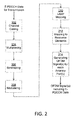
- FIG. 2 is a flow diagram of an example process for transmitting an enhanced control channel.
- FIG. 2 is meant to generally describe example processing steps for transmitting an E-PDCCH, and each of the steps will be described in more detail herein. Thus, FIG. 2 is meant to be read in conjunction and combination with the other disclosure contained in this detailed description.
- a transmitter and/or eNB may perform less than all the processing steps shown in FIG. 2 . For example, if the E-PDCCH is included in a single layer transmission, the transmitter/eNB may refrain from performing layer mapping and/or precoding. In an example, an eNB may transmit one or more E-PDCCHs to one or more WTRUs.
- the eNB may determine a subset a subframes on which to transmit the E-PDCCH.
- the E-PDCCH may be transmitted in every subframe.
- the E-PDCCH may be transmitted in less than every subframe.
- the E-PDCCH may be transmitted in every subframe, for example on a certain subset (including a single) of antenna ports.
- the E-PDCCH may be transmitted on a subset of subframes and on a subset (including a single) of antenna port(s).
- the term subset may refer to one or more members of a group, but not the entire group.
- an eNB may determine that there is enhanced control channel data to be transmitted in a given subframe.
- the eNB may perform channel coding of one or more E-PDCCH transmissions for one or more WTRUs.
- the output of the channel coding operation may be a sequence of M bit (i) coded bits for the i th E-PDCCH transmission of one or more E-PDCCH transmissions.
- Example channel coding schemes may perform one or more (in any combination and/or order) of error detection, error correcting, rate matching, interleaving, and/or control information mapping onto/splitting from physical channels.
- the eNB may multiplex one or more channel coded E-PDCCH transmissions.
- the eNB may scramble one or more coded E-PDCCH transmissions.
- the output of the scrambling operation may be a sequence of M tot scrambled bits.
- the eNB may modulate the sequence of scrambled bits.
- the result of the modulation may be a sequence of M symb complex-valued modulated symbols.
- Example modulation techniques may include Quadrature Phase-Shift Keying (QPSK), 16-Quadrature Amplitude Modulation (16-QAM), and/or 64-Quadrature Amplitude Modulation (64-QAM).
- the eNB may perform layer mapping and/or precoding.
- Layer mapping and/or precoding may refer to the mapping of E-PDCCH data to be transmitted to one or more antenna ports ( e.g. , transmission layers) for transmission over the wireless channel.
- the layer mapping and/or precoding operation may result in a block of M symb vectors.
- the p th element of the vector may correspond to the signal (or symbol(s)) to be transmitted over antenna port p.
- the eNB may map the resulting precoded vectors to resource elements in the time-frequency grid.
- each antenna port may have an associated time-frequency grid, and data corresponding to a specific antenna port may be mapped to the time-frequency grid associated with that specific antenna port.
- the eNB may map each modulated symbol for each antenna port (e.g., for each precoded vector) to a specific resource element of the OFDM time/frequency grid.
- a resource element may be defined by a pair of indices (k,l) where k is a subcarrier index and 1 is a time index.
- the eNB may generate an OFDM signal for each antenna port.
- Transmission over a given antenna port may be realized using one or more techniques, for example transmitting over a single physical antenna clement, transmitting over a plurality of weighted antenna elements, and/or other multiple antenna transmission techniques.
- a transmitter may ensure that two signals transmitted over the same antenna port experience the same or a similar transmission channel, provided that the propagation channel is relatively constant.
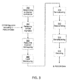
- FIG. 3 is a flow diagram of an example process for receiving an enhanced control channel.
- WTRU may receive one or more E-PDCCHs from one or more eNBs.
- FIG. 3 is meant to generally describe example processing steps for receiving an E-PDCCH, and each of the steps will be described in more detail herein. Thus, FIG. 3 is meant to be read in conjunction and combination with the other disclosure contained in this detailed description.
- a receiver and/or WTRU may perform less than all the processing steps shown in FIG. 3 . For example, if the E-PDCCH is included in a single layer transmission, the receiver/WTRU may refrain from performing layer demapping and/or spatial demultiplexing.
- the WTRU may determine a subset a subframes on which to monitor for the E-PDCCH.
- the E-PDCCH may be transmitted in every subframe.
- the E-PDCCH may be transmitted in less than every subframe.
- the E-PDCCH may be transmitted in every subframe, for example on a certain subset of antenna ports.
- the E-PDCCH may be transmitted on a subset of subframes and on a subset of antenna ports.
- a WTRU may determine to monitor for the E-PDCCH in a given subframe and/or on a given component carrier. For example, a WTRU may determine to monitor for the E-PDCCH in a given subframe based on a property of the subframe (e.g. , an E-PDCCH parameter) or based on predefined scheduling rules.
- the receiver e.g. , the WTRU
- the WTRU may attempts to decode the E-PDCCH by utilizing the knowledge of the processing steps at the transmitter.
- a WTRU may implement on or more processing steps where each processing step may perform the reverse operation of a corresponding processing step at the transmitter side.
- the WTRU may receive an OFDM transmission signal which may include a plurality of OFDM signals corresponding to a plurality of antenna ports.
- the WTRU may estimate the channel corresponding to each antenna port using the knowledge of a reference signal transmitted over this antenna port (e.g. , DM-RS).
- the reference signal for the antenna port may be precoded with the same precoding weights used to transmit user and control data on the antenna port.
- the WTRU may perform resource element demapping. For example, for each antenna port, the receiver/WTRU may demap symbols from resource elements according to the mapping used at the transmitter.
- the output of the demapping operation may be a block of M symb vectors where the p th element of a vector corresponds to the signal (or symbol) corresponding to antenna port p.
- a WTRU may perform layer demapping/spatial demultiplexing. For example, the WTRU may determine the complete modulated transmission from the eNB based on identifying the modulated transmissions for a plurality of transmission layers/antenna ports.
- the result of layer demapping may be a sequence of M symb complex-valued modulation symbols that correspond to the overall transmission across a plurality of spatial layers/antenna ports.
- the WTRU may demodulate the complex-valued modulation symbols.
- Example modulations may include QPSK, 16-QAM, and/or 64-QAM.
- the result of the demodulation operation may be a sequence of M tot scrambled bits.
- the WTRU may perform descrambling on the demodulated symbols (e.g. , the scrambled bits).
- the output of the descrambling operation may by a sequence of M tot coded bits, which may potentially correspond to at least one E-PDCCH transmission.
- the WTRU may perform demultiplexing on the coded bits.
- the WTRU may attempt to decode the coded bits.
- the receiver may attempt to decode at least one subset of the M tot coded bits and check if the decoding is successful by masking the information bits corresponding to the cyclic redundancy check (CRC) with at least one RNT1.
- CRC cyclic redundancy check
- the WTRU may not be aware of the actual number of E-PDCCH transmissions, aggregation levels, and/or positions of an E-PDCCH transmission in the sequence of coded bits. Thus, the WTRU may determine the subsets of coded bits for the decoding attempts according to at least one search space.
- a subframe may be defined such that an enhance control channel is included in areas of the subframe typically utilized for PDSCH data.
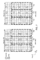
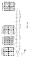
- FIG. 4 illustrates subframes with an example enhanced control channel.
- the performance improvement of the PDCCH channel may be accomplished by sending some or all of the control channel information to a WTRU using resource elements that are traditionally associated with the PDSCH region. As such, by relying on the DM-RSs, the receiving WTRU may demodulate and decode the PDSCH and or enhance control channel information with a higher level of confidence.
- the E-PDCCH may be sent from an eNB and received by a WTRU.
- the E-PDCCH may occupy resource elements outside the legacy "control region" of the subframe (if present), as in the example shown in FIG. 4 .
- Transmission of the E-PDCCH may be performed using pre-coded reference signals such as, but not limited to, UE-specific reference signals and/or DM-RSs.
- the E-PDCCH may also occupy resource elements in the legacy control region.
- the E-PDCCH may be included in the PDSCH region of a subframe.
- the E-PDCCH may occupy a set of resource elements defined by a RB Assignment in the frequency domain (which may be in terms/units of REs, subcarriers, frequency, resource blocks (RBs), physical resource blocks (PRBs), virtual resource blocks (VRBs), etc.), which may be valid for a specified amount of OFDM symbols in the time domain.
- the frequency division multiplexing (FDM) example shown in FIG. 4 includes an E-PDCCH region that is present for each of the OFDM symbols in the PDSCH region of the subframe.
- the legacy PDCCH region may be present in the beginning of the subframe (e.g ., in the first 1-3 OFDM symbols of the subframe).
- the E-PDCCH is shown to occupy resource elements in the PDSCH region of the subframe in FIG. 4
- the E-PDCCH region may also occupy parts of the legacy PDCCH region.
- the E-PDCCH may occupy a specified E-PDCCH Bandwidth (BW) assignment in the frequency domain.
- BW E-PDCCH Bandwidth
- the E-PDCCH region may span the time between N Start and N End in the time domain. N Start and N End may be expressed in terms of time, resource elements, OFDM symbols, slots, and/or the like.
- the information carried in the enhanced control channel may include any information that may be carried with the legacy PDCCH channel.
- the E-PDCCH may be used to send one or more of uplink (UL) grants and associated UL parameters, downlink (DL) assignments and associated DL parameters, TPC commands, aperiodic channel state information (CSI), sounding reference signal (SRS) requests, random access responses, semi-persistent scheduling (SPS) activations and/or releases, broadcast channel (BCH) resource indications, any other associated parameters, and/or any combination of the above mentioned parameters.
- UL uplink
- DL downlink
- TPC commands aperiodic channel state information
- CSI channel state information
- SRS sounding reference signal
- SPS semi-persistent scheduling
- BCH broadcast channel
- the E-PDCCH may also be used to send any information that is carried on the legacy PHICH channel (e.g., Ack or Nack), any information that is included one the legacy physical control format indicator channel (PCFICH), and/or any other types of new control information.
- the information described herein may be structured according to existing DCI formats used in the legacy PDCCH, or according to newly defined DCI formats.
- the E-PDCCH may be defined in order to eliminate older, legacy control channels (e.g. , the legacy PDCCH, PHICH, and/or PCFICH).
- the E-PDCCH may be used to supplement or complement the legacy control channels.
- a WTRU may decode the E-PDCCH alone in a given subframe, or may decode the E-PDCCH along with one or more of the legacy PDCCH, PHICH and/or PCFICH (or any combination thereof).
- a WTRU may first detect the presence and/or decode the E-PDCCH. For example, the E-PDCCH may not be included in each and every subframe (or in every layer of a subframe including multiple layers), so the WTRU may first make a determination of whether the E-PDCCH is to be included in a given subframe. For example, if the WTRU determines that a given subframe does not include a potential E-PDCCH candidate, the WTRU may choose to refrain from attempting to decode the E-PDCCH in that subframe in order to save processing resources and/or power. Thus, the WTRU may selectively determine in which subframes E-PDCCH decoding and reception may be attempted.
- the WTRU may determine whether to monitor for the E-PDCCH in that subframe.
- methods may be employed that allow the WTRU to determine whether E-PDCCH decoding should be attempted at all in a subframe. For example, a WTRU may identify certain subframes that no E-PDCCH is expected, and thus the WTRU may determine that there is no need to attempt to decode the E-PDCCH in the identified subframes. The determination of whether to monitor for the E-PDCCH in a given subframe may be based on the transmission mode configured for the WTRU.
- the WTRU may monitor for the E-PDCCH if it is configured with certain transmission modes involving the use of DM-RS or UE-specific reference signals. For example, if the current configuration of the WTRU does not utilize DM-RSs, then the WTRU may determine to refrain from attempting to monitor the E-PDCCH. In one example, the WTRU may monitor for the E-PDCCH only if it is configured with certain transmission modes involving the use of DM-RS or UE-specific reference signals, while WTRUs not configured with certain transmission modes involving the use of DM-RS or UE-specific reference signals may determine not to monitor E-PDCCH.
- the determination whether to monitor for the E-PDCCH may be based on a property of the subframe. For example, the determination may be based on the type of subframe, such as whether the subframe is a normal subframe, a multi-media broadcast over a single frequency network (MBSFN) subframe, an almost blank subframe (ABS), and/or the like. The determination may be based on whether the subframe belongs to a subset of subframes signaled by higher layers, which may be specified in terms of frame and/or subframe numbers.
- higher layers may refer to communication protocol layers above the physical layer (e.g. , higher layers - the medium access control (MAC) layer, the radio resource control (RRC) layer, packet data convergence protocol (PDCP) layer, etc.) may indicate to the physical layer the identity of subframes to monitor for the E-PDCCH.
- the determination whether to monitor for the E-PDCCH may be based on whether a PDCCH is successfully received in the legacy control region of the subframe. For example, if the PDCCH is successfully decoded by the WTRU (possibly in certain specified search space(s)) the WTRU may determine not to monitor for the E-PDCCH, for example in non-control regions of the subframe in which the PDCCH was successfully received. In an example, the WTRU may determine not to monitor the E-PDCCH if any PDCCH is successfully decoded by the WTRU using certain radio network temporary identifier (RNTI) values.
- RNTI radio network temporary identifier
- the WTRU may determine not to monitor the E-PDCCH.
- the WTRU may determine not to monitor for the E-PDCCH in the subframe.
- C-RNTI cell-RNTI
- the C-RNTI is used here for purposes of illustration, and there may be scenarios during which a WTRU may receive a PDCCH masked with its C-RNTI and still attempt to decode the E-PDCCH in a subframe.
- successfully decoiding a legacy PDCCH transmission that is masked with the C-RNTI for the WTRU may trigger the WTRU to monitor for and/or attempt to decode the E-PDCCH in a given subframe (e.g. , the same subframe in which the legacy PDCCH is received and/or some subframe in the near future such as four subframes in the future).
- the WTRU may determine to attempt to monitor for and/or decode the E-PDCCH in that subframe.
- the WTRU may determine that E-PDCCH should be monitored if it does not successfully decode the PDCCH in a given subframe.
- a supporting PDCCH may be used to support the detection, decoding, demodulation, etc. of an E-PDCCH.
- a supporting PDCCH may be a legacy/R-8 PDCCH that is included in the same subframe as a received E-PDCCH.
- the supporting E-PDCCH may be a modified version of the legacy/R-8 PDCCH, for example with enhancements to signal the presence and or location of the E-PDCCH.
- Using a supporting PDCCH to signal parameters related to the E-PDCCH may allow for the dynamic modification of E-PDCCH parameters on a per-subframe basis.
- the eNB may be able to dynamically schedule the PDSCH while simultaneously scheduling the E-PDCCH in the same subframe.
- the E-PDCCH may exist in different locations (e.g ., within the different parts/REs of the PDSCH region of the subframe) for different subframes. Allowing the E-PDCCH to exist in different locations of a subframe at different times provides additional scheduling flexibility as compared to the E-PDCCH being located in specific, predefined locations in every subframe (or subsets of subframes). Additionally, signaling the location of the E-PDCCH in a supporting PDCCH may lead to reduced blind decoding complexity at the WTRU.
- the WTRU may determine that E-PDCCH should be monitored if such a supporting PDCCH is decoded. In an example, the WTRU may determine that E-PDCCH should be monitored only if such a supporting PDCCH is decoded. In another example, if an indication in the supporting PDCCH is set to a specific value, the WTRU may determine whether or not to monitor the E-PDCCH based on the value. For example, a field in the supporting PDCCH may be indicative of whether an E-PDCCH transmission is included in the subframe containing the supporting PDCCH or some other subframe. If transmissions are occurring on multiple transmission layers and/or multiple component carriers, the supporting PDCCH may indicate the identity of the transmission layer and/or component carrier that includes the E-PDCCH.
- the WTRU may successfully decode the E-PDCCH.
- the WTRU may attempt to process and decode the E-PDCCH in the subframe and/or on the component carrier.
- the WTRU may identify at least one E-PDCCH region where an E-PDCCH may potentially be received.
- the term E-PDCCH region may refer to resource elements or groups of resource elements in a given subframe which may be used for E-PDCCH transmission.
- a WTRU may identify the E-PDCCH region as a subset of the resource elements of the subframes, such as a subset of the REs included in the PDSCH region of a subframe. If multiple transmission layers are used (e.g., MIMO techniques are utilized) the E-PDCCH region may be included in a single transmission layer or multiple transmission layers.
- an E-PDCCH region may include at least one set of resource elements for a given component carrier in the subframe.
- the WTRU may attempt to decode at least one set of E-PDCCH candidates in at least one search space.
- a E-PDCCH candidate may be a set of REs within the E-PDCCH region that could potentially include a E-PDCCH transmission.
- the WTRU may assume a certain set of transmission characteristics in order to attempt to decode the E-PDCCH for a given E-PDCCH candidate in the E-PDCCH region. Attempting to receive the E-PDCCH may include one or more processing steps.
- a WTRU may attempt to perform one or more of frequency/time demultiplexing (e.g. , obtaining the subset of resource elements used for E-PDCCH in time/frequency domain), spatial demultiplexing/layer demapping (e.g. , obtaining the signal from each antenna port used for the E-PDCCH), demodulation, descrambling, decoding (for example using a CRC), and/or any combination thereof.
- frequency/time demultiplexing e.g. , obtaining the subset of resource elements used for E-PDCCH in time/frequency domain
- spatial demultiplexing/layer demapping e.g. , obtaining the signal from each antenna port used for the E-PDCCH
- demodulation e.g. , descrambling
- decoding for example using a CRC
- the E-PDCCH may be transmitted and received on specified antenna ports.
- a WTRU may determine one or more antenna ports from which to decode an E-PDCCH candidate or a set of E-PDCCH candidates in corresponding resource elements.
- the WTRU may associate the modulated symbols that correspond to the determined antenna ports for E-PDCCH transmission with the data that corresponds to an E-PDCCH candidate or set of E-PDCCH candidates.
- the WTRU may determine a block of M symb modulation symbols that correspond to potential E-PDCCH candidates transmitted on the determined antenna ports.
- the transmitter at the network may utilize one or more antenna ports, for example antenna port p , for the transmission of one or more E-PDCCHs.
- the one or more antenna ports may correspond to an antenna port on which an already defined reference signal is transmitted.
- the E-PDCCH may be transmitted and received on antenna ports 0 to 3, which may include cell-specific reference signals (CRS).
- the E-PDCCH may be transmitted and received on antenna port 4, which may include MBSFN reference signals.
- the E-PDCCH may be transmitted and received on antenna ports 5 or 7 to 16, which may include UE-specific or demodulation reference signals (DM-RSs).
- DM-RSs UE-specific or demodulation reference signals
- the one or more antenna ports used to transmit the E-PDCCH may also include one or more new antenna ports.
- the newly defined antenna ports may be utilized to transmit newly defined reference signals. Whether a newly defined set/subset of antenna ports and/or reference signals are used or an existing set/subset are used may depend on the type of subframe ( e.g. , whether the subframe is a MBSFN subframe or a normal subframe). Whether a newly defined set/subset of antenna ports and/or reference signals are used or an existing set/subset are used may depend the type of carrier where E-PDCCH is decoded (such as whether the carrier is a normal/primary carrier or an extension/secondary carrier). The identity of the antenna ports used for E-PDCCH transmission may also be indicated dynamically to the WTRU in a supporting PDCCH.
- the receiver at the WTRU may determine the identity of one or more antenna ports from which to attempt to decode one or more E-PDCCHs. Once the WTRU has determined the one or more antenna ports to be utilized for E-PDCCH reception, the WTRU may estimate the channel corresponding to each antenna port by measuring the corresponding reference signal transmitted over this antenna port.
- the WTRU may determine that corresponding reference signals in different resource blocks (or parts of resource blocks) that are adjacent in time and/or frequency may be precoded for the same E-PDCCH transmission. For example, if UE-specific reference signals are utilized to facilitate E-PDCCH reception, the WTRU may determine that a resource element that includes a reference signal in proximity to (and/or overlapping with) an E-PDCCH candidate in an E-PDCCH region may be precoded in the same manner as the E-PDCCH candidate.
- the determination that the adjacent reference signals may be precoded for the same E-PDCCH transmission may be based on whether the reference signals are included in parts of resource block(s) onto which the same control channel element(s) map. Determining that the same E-PDCCH transmission occurs in adjacent resource blocks may also be determined based on one or more of the methods for determining an identification and/or transmission characteristics of an E-PDCCH candidate described herein. For example, the relationship between precoded reference signals and antenna ports for E-PDCCH transmission may be specified using explicit higher layer signaling. In an example, the relationship between precoded reference signals and antenna ports for E-PDCCH transmission may be implicitly determined from an E-PDCCH mode of operation.
- the relationship between precoded reference signals and antenna ports for E-PDCCH transmission may be implicitly determined based on whether the WTRU is operating in a "frequency-localized” or a "frequency-distributed” mode, as may be described herein.
- the relationship between precoded reference signals and antenna ports for E-PDCCH transmission may be dynamically signaled using a supporting PDCCH, for example on a per subframe basis.
- a resource element that may typically carry a reference signal that may be used for channel estimation may carry other types of signals that are not used for demodulation purposes.
- the WTRU may assume that a resource element that would otherwise carry a reference signal (e.g ., DM-RS) on an antenna port used for E-PDCCH, may instead be used for another type of signal, for example if such a different signal is indicated to be present ( e.g ., when signaled by higher layers, when a formula indicates as such, when configured by the network, etc.). If so, the WTRU may determine not use the resource element for the purpose of channel estimation. This method may be utilized in case of collision with at least one of the following signals: CSI-RS (e.g., if it is not a "zero-power" CSI-RS) and/or positioning reference signal (PRS).
- CSI-RS e.g., if it is not a "zero-power" CSI-RS
- PRS positioning reference signal
- a WTRU may determine the number and identity of antenna ports used for E-PDCCH transmission.
- the following paragraphs describe example methods that may be used by the transmitter (e.g., the eNB) and the receiver (e.g., the WTRU) to determine a set or subset of antenna ports for transmission or reception of E-PDCCH, as well as the number of antenna ports in the set/subset.
- the transmitter/eNB may utilize the same set of antenna ports for all symbols corresponding to a single E-PDCCH transmission.
- the eNB may determine which antenna ports to use based on the identity of the WTRU targeted for reception of the E-PDCCH.
- two or more antenna ports may be utilized for transmission of the symbols associated with a given E-PDCCH transmission.
- the WTRU may determine number of antenna ports and/or the set of antenna ports associated with a given E-PDCCH transmission based on higher layer signaling.
- the WTRU may determine number of antenna ports and/or the set of antenna ports associated with a given E-PDCCH transmission dynamically, either implicitly and/or explicitly.
- the WTRU may implicitly and dynamically determine number of antenna ports and/or the set of antenna ports used for E-PDCCH transmission based on a property of the subframe or a configured transmission mode.
- the WTRU may dynamically determine the number of antenna ports and/or the set of antenna ports used for E-PDCCH transmission based on explicit signaling from the eNB, for example using a supporting PDCCH.
- An example of higher layer signaling that may be used to configure the WTRU for reception of the E-PDCCH may include RRC signaling.
- the set of antenna ports used for transmission of the E-PDCCH may be pre-determined.
- the set of antenna ports used for transmission of the E-PDCCH may be a function of another parameter such as the cell identity.
- a WTRU may perform a plurality of E-PDCCH reception attempts for a set of candidate antenna ports.
- the WTRU may attempt to process the E-PDCCH over all antenna ports or a subset of antenna ports.
- the WTRU may be unaware of the actual antenna ports used for E-PDCCH transmission prior to beginning to process the subset of antenna ports.
- the set of antenna ports may be initially narrowed to a subset of potential antenna ports, and the E-PDCCH transmission may be contained on one or more of the subset of potential antenna ports.
- the WTRU may attempt to process each of the potential ports in order to determine the subset of the potential ports that include an E-PDCCH transmission.
- the transmitter/eNB may utilize, and the receiver/WTRU may determine, a set of one or more antenna ports that are associated with an E-PDCCH transmission.
- the number and/or identity of the antenna ports used for E-PDCCH transmission may depend on one or more parameters.
- the number and/or identity of the antenna ports used for E-PDCCH transmission may depend on the identity of the CCE(s) and/or E-CCE(s) the symbols transmitted over the antenna port(s).
- the number and/or identity of the antenna ports used for E-PDCCH transmission may depend on the identity of the resource elements (REs) that the symbols transmitted over the antenna port(s) are mapped to.
- REs resource elements
- the REs that the symbols transmitted over the antenna port(s) are mapped to may be defined by the identity of the physical resource block(s) (PRB) or virtual resource block(s) (VRB) associated with an transmission using the antenna port(s) (e.g., a PRB index or VRB index).
- the REs that the symbols transmitted over the antenna port(s) are mapped to may be defined by the location in time of the transmission, such as the time slot associated with the transmission.
- the number and/or identity of the antenna ports used for E-PDCCH transmission may depend on which resource element group(s) (REG) or enhanced resource element group(s) (E-REG) the symbols are mapped to. More information regarding REGs and E-REGs is included below.
- the number and/or identity of the antenna ports used for E-PDCCH transmission may depend on the timing and/or type of subframe in which the E-PDCCH is received.
- the number and/or identity of the antenna ports used for E-PDCCH transmission may depend on the subframe number, whether the subframe is an MBSFN or a normal subframe, and/or whether a CRS is transmitted in the subframe.
- the number and/or identity of the antenna ports used for E-PDCCH transmission may depend on a parameter, such as the cell identity or another parameter provided to the WTRU.
- Associating the antenna port used for E-PDCCH transmission with another parameter may allow for the assignment of antenna ports among a plurality of possible sets, thereby permitting interference reduction between points transmitting different E-PDCCHs. For example, different antenna ports may be assigned to each of the potential transmitters in order to mitigate any adverse effects associated with the multiple transmissions.
- the use of multiple sets or subsets of antenna ports among different E-PDCCH receiver (e.g. , WTRUs) may be beneficial to facilitate multiplexing of multiple E-PDCCH transmissions into a single RB and/or pair of RBs.
- the antenna port(s) used for transmission of an E-PDCCH to a particular WTRU may be a function of the E-REG index r and a parameter N ID .
- N ID may correspond to the cell identity or to another parameter.
- N ID may correspond to a transmission point identity, which may be provided in a dedicated manner.
- a PRB-pair includes symbols corresponding to 4 different CCEs/E-CCEs where each E-CCE occupies one fourth of the REs of the PRB pair, up to 4 different antenna ports may be used to decode the symbols corresponding to each of the 4 CCEs/E-CCEs.
- the antenna port(s) used for transmission of the E-PDCCH may be a function of the time slot within the same PRB pair.
- Equation (2) may be utilized, and for the second time slot Equation (3) may be utilized.
- p 7 + N ID mod 2
- the REs of the six subcarriers highest in frequency may be decoded using a first antenna port (e.g. , antenna port #7) while the REs of the 6 sub-carriers lowest in frequency (possibly corresponding to a second CCE/E-CCE) may be decoded using a second antenna port ( e.g. , antenna port #8).
- a first antenna port e.g. , antenna port #7
- a second antenna port e.g. , antenna port #8
- the set/subset of antenna ports used for r a given E-CCE or E-PDCCH transmission in a specified E-REG, PRB, VRB, time slot and/or subframe may be determined according to a pseudo-random pattern.
- the pseudo-random pattern may be generated by a Gold code.
- the use of such pseudo-random pattern may be beneficial for randomizing interference between E-PDCCH transmissions occurring from cells or transmission points controlled by uncoordinated schedulers.
- the pattern may determine whether a first set/subset of antenna ports should be used (e.g. , antenna port set ⁇ 7, 8 ⁇ ) or whether a second set/subset of antenna ports should be used (e.g.
- antenna port set ⁇ 9, 10 ⁇ should be used for E-PDCCH transmission.
- Use of a pseudo-random code generator may facilitate minimizing the number of instances where adjacent points controlled by different schedulers use the same set of antenna ports for a given RB. For example, if the port is randomly selected among a grouping of antenna ports(s) that have equal probability of selection, then the chances two schedulers would select the same antenna ports for a given transmission may be mitigated.
- a WTRU may obtain the initial value of the pseudo-random generator from parameters provided by higher layers. The initial value of the pseudo random sequence may be determined based on one or more E-PDCCH parameters.
- the WTRU may obtain the initial value of the pseudo-random generator from other techniques for determining E-PDCCH parameters, such as signaling using supporting PDCCH.
- the initial value of the pseudo-random generator may be a function of the subframe number or the slot number in the frame to achieve randomization in the time domain.
- the initial value of the pseudo-random generator may be obtained from Equation (4).
- c init ⁇ n s / 2 ⁇ ⁇ 2 9 + N ID
- n s may be the slot number and N ID may correspond to an identity such as a physical cell identity or some other parameter.
- NID may correspond to a transmission point identity and/or a different parameter ( e.g ., one or more E-PDCCH parameters) that the WTRU is capable of determining either explicitly or implicitly.
- a WTRU may determine that E-PDCCH detection may be attempted on more than one antenna port. For example, the WTRU may determine that the E-PDCCH will be transmitted on a single antenna port (a single antenna port is used for purposes of illustration, the following principles also apply if the E-PDCCH is included on more than one antenna port), but may be unable to explicitly determine the identity of the antenna port prior to beginning downlink processing for the subframe including an E-PDCCH candidate. Instead, the WTRU may identify on or more potential antenna ports that may include an E-PDCCH transmission and attempt decoding separately on each of the potential antenna ports. Blind decoding of a subset of antenna ports for E-PDCCH reception may allow for more flexibility for the transmitter in the utilization of antenna ports.
- the WTRU may determine the potential antenna ports and decode potential E-PDCCH candidates in the same RE(s), E-REG(s), CCE(s)/E-CCE(s), and/or whole E-PDCCH regions for each of the potential antenna ports. In this case, the WTRU may obtain one or more than one symbol for each RE on each port, as described as layer mapping/de-mapping processing sections.
- the mapping rule may also be determined from higher layer signaling, dynamically from a supporting PDCCH, and/or dynamically/semi-dynamically determined based on observed or signaled E-PDCCH parameters.
- the method that is used for the determination of the set/subset of antenna ports used for E-PDCCH transmission may depend on a parameter provided by higher layers and/or may be implicit based on an E-PDCCH mode of operation configured by higher layers.
- the antenna port used for an E-PDCCH transmission may be constant or fixed.
- the antenna port used for an E-PDCCH transmission may be fixed over at least one PRB in order to enhance channel estimation.
- reference signals may be utilized.
- the transmitter may generate the reference signals in order to facilitate channel estimation at the receiver.
- precoded reference signals may be utilized in order to estimate the effective channel conditions on the one or more specific antenna ports.
- the reference signal may be precoded with the same precoding weights as are used for E-PDCCH data transmitted on the corresponding antenna port(s).
- Reference signals such as DM-RS may be derived from a pseudo-random sequence.
- a pseudo-random sequence generator at the transmitter and/or receiver may be initialized with a value c init at the beginning of each subframe.
- the DM-RS(s) that are generated using different values of c init may be generated to have low cross-correlation, and DM-RS(s) generated using the same value of c init but transmitted over different antenna ports may be orthogonal.
- the value of c init may be a function of the slot number and of different parameters, for example as shown in Equation (5).
- c init ⁇ n s / 2 ⁇ + 1 ⁇ 2 N ID X + 1 ⁇ 2 16 + n SCID
- two values of c init may be distinct or different if at least one of the values of N ID X and n SCID are different.
- at least one of the terms N ID X or n SCID may be set to a pre-determined value, and the other parameter may be varied. In an example, both terms may be varied, for example semi-statically or dynamically.
- at least one of the terms N ID X or n SCID may be set to zero.
- the parameter N ID X and/or n SClD may represent or correspond to values specific to a WTRU ( e.g., cell identity).
- values for the parameter N ID X and/or n SCID may be selected irrespective of a current state or status of the WTRU, for example if they are predetermined.
- the transmitter/eNB may set the values of N ID X and/or n SClD to the same values for all E-PDCCH transmissions regardless of which WTRU is the intended recipient of the E-PDCCH.
- the value of N ID X may be set to the physical cell identity of the cell and the value of n SCID may be set to an arbitrary value (such as zero).
- the receiver/WTRU may assume that the generator is initialized with the above formula where N ID X is set to the physical cell identity of the serving cell and n SCID set to the arbitrary value.
- the transmitter/eNB may set the value of N ID X and/or n SCID to different values depending on the E-PDCCH transmission. Setting one or more of N ID X and/or n SCID to different values depending on the corresponding E-PDCCH transmission may facilitate the use of non-orthogonal DM-RS(s) from different transmission points within the same cell.
- the transmitter/eNB may set N ID X and/or n SCID to a value specific to the transmission point from which E-PDCCH transmission takes place.
- the receiver/WTRU may determine the value of N ID X and/or n SCID from higher-layer signaling.
- the receiver/WTRU may determine the value of N ID X and/or n SCID based on a parameter(s) that may be linked to and/or may correspond to the CSI-RS configuration.
- the WTRU may be provided with a single value of N ID X (and/or a single value of n SCID ) or with more than one value of N ID X and/or n SCID .
- the WTRU may determine which value or pair of values to use based at least in part on the identity of the resource block in which the DM-RS is received.
- the WTRU may assume that the value of pair of values is a function of the resource block where the DM-RS is received.
- the WTRU may also attempt reception using each value (or pair of values).
- the WTRU may determine the value of N ID X and/or n SCID dynamically from a supporting PDCCH.
- the WTRU may dynamically determine the values for N ID X and/or n SCID using some other form of dynamic signaling and/or processing.
- the pseudo-random sequence may be re-initialized on a slot basis instead of on a subframe basis. If the pseudo-random sequence is re-initialized on a per slot basis, a different value of c init may be used for each of the two slots of the same subframe. For example, the value of c init may be determined based on Equation (6) and/or Equation (7).
- n SCID 0 may represent the n SCID value for slot 0 of a subframe (e.g., the first slot of the subframe).
- n SCID 1 may represent the n SCID value for slot 1 of a subframe (e.g., the second slot of the subframe).
- n SClD may depend on the slot value for the subframe .
- the values for n SCID 0 and/or n SCID 1 may be determined by the WTRU in a manner similar to that of n SCID , as described herein.
- the difference n SCID 1 ⁇ n SCID 0 may be set to a predetermined value.
- the initial value of the pseudo-random generator (c init ) may be expressed as shown in Equation (9).
- c init ⁇ n s / 2 ⁇ + 1 ⁇ 2 N ID X , s + 1 ⁇ 2 16 + n SCID
- the two slot dependent values for N ID X e.g., N ID X , 0 and N ID X , 1
- both h N ID X and n SClD may be slot-dependent values.
- the transmitter/eNB may utilize different initialization values for the pseudo random generator (e.g ., c init ) for different physical resource blocks, for different virtual resource blocks, and/or between two resource blocks within a resource block pair. Doing so may allow for greater scheduling flexibility.
- a WTRU may assume that the initialization value c init is a function of the physical resource block and/or virtual resource block, for example according to a mapping which may be pre-determined or signaled by higher layers and/or dynamically ( e.g. , using a supporting PDCCH).
- a new set of antenna ports/and or reference signals may be defined.
- the new reference signals may occupy a different set of REs than are used for existing reference signals.
- the DM-RS ports for E-PDCCH transmission may be defined as ports ⁇ 23, 24 ⁇ .
- FIG. 5 illustrates an example of the DM-RS ports ⁇ 23, 24 ⁇ for E-PDCCH.
- the horizontal axis may represent the frequency domain and the vertical axis may represent the time domain.
- RB-pair 500 may include a plurality of E-CCEs (e.g., E-CCE #n 502, E-CCE #n+1 504, E-CCE #n+2 506, and E-CCE #n+3 508).
- CRSs may not be used, although CRS may also be included in specified resource elements.
- E-CCE # n+2 506 is shown to include two antenna/DM-RS ports (e.g., DM-RS port #23 510 and DM-RS port #24 520), although there may be other antenna ports spatially multiplexed over E-CCE #n+2 506.
- DM-RS port #23 510 and DM-RS port #24 520 may occupy the same time-frequency resources in a given subframe.
- DM-RS reference signals specific to the particular antenna port may be included in the shaded resource elements of DM-RS port #23 510 and DM-RS port #24 520.
- the DM-RSs may be used to properly estimate the channel for each antenna port.
- the DM-RS ports may be multiplexed with time domain orthogonal cover code (OCC).
- OOC time domain orthogonal cover code
- the DM-RS ports may be used for operations in addition to CDM multiplexing (e.g., are not be restricted to the CDM multiplexing).
- the transmitter/eNB may map each E-PDCCH symbol y (p) (i) for each antenna port p to a specific RE of the OFDM time/frequency grid for a given subframe and a given component carrier.
- a set of REs over which the E-PDCCH symbols may potentially be mapped in a subframe, which may be for one or more E-PDCCH transmissions, may be referred to as an E-PDCCH region.
- the E-PDCCH region may be the complete set of resource elements in a subframe for a carrier.
- the E-PDCCH region may be a subset of the set of resource elements in a subframe for a carrier.
- the E-PDCCH region may include REs that are in the legacy PDSCH region of the subframe.
- the WTRU may determine the identity and/or location of the E-PDCCH region implicitly or explicitly, as is described herein.
- the receiver at the WTRU may identify one or more E-PDCCH region(s) to de-map E-PDCCH symbols from REs for each antenna port.
- the UE may demap all E-PDCCH symbols y (p) (i) of the E-PDCCH region or may elect to demap a subset of E-PDCCH symbols corresponding to at least one E-PDCCH candidate according to a defined search space.
- a search space within the E-PDCCH region may refer to a subset of the REs in the E-PDCCH region.
- the E-PDCCH region may include one or more UE-specific search spaces (e.g ., search spaces that are specific to a particular WTRU) and/or one or more common search spaces (e.g., search spaces that may be shared among a plurality of WTRUs).
- Each search space may include one or more E-PDCCH candidates.
- the E-PDCCH region of a given subframe may be defined in terms of one or more of time-domain information, frequency-domain information, and/or a set of resource blocks.
- the time-domain information used to define the E-PDCCH region may include information relating to at least one OFDM symbol that includes the E-PDCCH.
- the E-PDCCH may be defined by a starting OFDM symbol and ending OFDM symbol if the E-PDCCH is contiguous in the time domain.
- the E-PDCCH region may also be defined based on at least one time slot.
- the E-PDCCH region may occupy the first time slot, the second time slot, and/or both time slots of the subframe.
- the frequency-domain information used to define the E-PDCCH region may be defined by a bitmap.
- the E-PDCCH region may be defined in the frequency domain based on a set of resource blocks used to transport the E-PDCCH.
- the resource blocks may be defined in terms of one or more physical resource blocks, one or more virtual resource blocks, and/or a resource block allocation.
- a resource block allocation may be defined in terms of a type of resource allocation ( e . g ., localized or distributed).
- a resource block allocation may be defined by a set of bits indicating a set of physical or virtual resource blocks, where the mapping may be according to existing specifications or according to a newly defined rules.
- the WTRU may determine the starting and ending OFDM symbols of E-PDCCH region in various manners. For example, a WTRU may determine the starting and ending OFDM symbols of E-PDCCH region according to explicit signaling, for example higher layer signaling or physical layer signaling (e.g ., PCFICH). The starting and ending OFDM symbols may be different between the first and the second slot of a subframe.
- explicit signaling for example higher layer signaling or physical layer signaling (e.g ., PCFICH).
- PCFICH physical layer signaling
- the parameter provided by higher layer may override the information detected by the WTRU from processing PCFICH (e.g., if PCFICH exists in the subframe).
- PCFICH e.g., if PCFICH exists in the subframe.
- ePDCCH_StartSymbol is configured by higher layers (e.g., RRC).
- the WTRU may determine the starting and ending OFDM symbols according to Table 1. The values shown in Table 1 are for purposes of illustration. Other values may be utilized.
- the WTRU may determine the last OFDM symbol of the E-PDCCH region based on the determined first OFDM symbol of the E-PDCCH region or vice versa.
- the PDCCH-less subframes may be particularly useful in heterogeneous networks where interference caused by the macro cell adversely impacts the WTRUs served by the low power nodes (e.g ., femto cells or pico cells).
- the WTRU may determine the resource elements used for E-PDCCH detection depending on the presence of other legacy DL control channels (e.g ., PCFICH, PHICH, etc.) in a given subframe. For example, if the legacy PCFICH and PHICH control channels are absent in a subframe, the WTRU may assume that E-PDCCH is transmitted on all resource elements within the first slot of a subframe, with the exception of resource elements reserved for reference signals.
- legacy DL control channels e.g ., PCFICH, PHICH, etc.
- the WTRU may assume that E-PDCCH is transmitted on all resource elements within the first slot of a subframe except resource elements reserved for PCFICH, PHICH, and/or reference signals.
- the modulated control information symbols for E-PDCCH may be mapped on resource element groups that are not used for PCFICH and/or PHICH.
- the modulated control information symbols for E-PDCCH may be skipped by the demapper at the WTRU.
- the presence or absence of legacy control channels in a given subframe may indicate to the WTRU that the E-PDCCH region is present in the subframe.
- the WTRU may determine the location of the E-PDCCH region based on a current configuration.
- the WTRU may implicitly determine that the E-PDCCH is located on a subset of the REs of the subframe if one or more legacy control channels are absent and/or present in the subframe.
- Types of E-PDCCH regions may be defined according to whether the corresponding resource allocation in the frequency domain is localized (e.g. , frequency-selective) or distributed ( e.g. , frequency-distributed or frequency-diversity).
- Some examples of resource block allocations for the E-PDCCH follow.
- the resource block allocation may comprise a number of resource blocks around the center of the carrier.
- the resource block allocation may comprise of equally spaced PRBs in the frequency domain.
- an RB or RB-pair (and/or PRB or PRB pair and/or VRB/VRB pairs) based resource definition with a bitmap indication may be utilized.
- using a bitmap to define the E-PDCCH region may allow for fully flexible resource allocation for the E-PDCCH.
- a bitmap may indicate RB(s) or RB-pair(s) (and/or PRB/PRB pairs and/or VRB/VRB pairs) used for E-PDCCH transmission.
- the number of bits for the bitmap may be 2xN RB(DL) bits or N RB(DL) bits according to the minimum resources available for the E-PDCCH, where N RB(DL) may be the number of resource blocks in the subframe.
- the bitmap indicating E-PDCCH may be indicated to a WTRU via the legacy PDCCH, a supporting PDCCH, RRC signaling, using a broadcast channel, and/or a combination thereof.
- the RB and/or PRB pairs allocated for E-PDCCH transmission may be distributed in the frequency domain.
- a first PRB may be located in the upper half of the system bandwidth and a second PRB may be located in the lower half of the system bandwidth (e.g. , the opposite ends of the system bandwidth).
- This scheme may be used to maximize the achievable gain through frequency diversity.
- the WTRU may determine the location of the second PRB within a PRB pair implicitly from the indicated location of the first PRB. Determining the location of the second PRB implicitly may lower the signaling overhead for E-PDCCH resource indication.
- a bitmap may be used to indicate the first PRB, and the WTRU may derive a bitmap associated with the second PRB using a fixed offset.
- a RBG may be the minimum resource granularity for the E-PDCCH.
- a RBG may be one or more resource blocks and/or physical resource blocks in a given time slot.
- the number of resource blocks include in a resource block group may vary and may depend on the system bandwidth.
- a bitmap may be used to indicate which RBG(s) are used for E-PDCCH.
- the number of bits for bitmap may be (N RB(DL) /P) bits, where P may be the size of a RBG.
- the bitmap indicating E-PDCCH may be indicated to a WTRU via the legacy PDCCH, a supporting PDCCH, RRC signaling, and/or broadcasting channel.
- Table 2 indicates an example relationship between the system bandwidth (in terms of number of DL RBs) and the RBG size.
- Table 2 System Bandwidth N RB(DL) RBG Size (P) ⁇ 10 1 11-26 2 27-63 3 64-110 4
- a RBG-based resource definition with pre-defined allocations may be specified.
- a subset of RBG(s) may be used for E-PDCCH transmission.
- the subset of RBG(s) may be identified by the physical cell ID (e.g., PCI/ N cell,id ) for the serving cell.
- the subset of RBG(s) may be determined based on a parameter provided to the WTRU by higher layers.
- the subset of RBG(s) that define the E-PDCCH region may be identified in an RRC information element, which may be received from an eNB.
- the the subset of RBG(s) that define the E-PDCCH region may be received, for example via an RRC information element, as part of the CSI-RS configuration for the WTRU.
- a single PRB or a single PRB-pair may be associated with the E-PDCCH region for a given cell.
- the PRB or PRB-pair position for a given cell may be identified based on the PCI.
- FIG. 6 illustrates an example E-PDCCH resource allocation according to PCI.
- each of RBG1 602, RBG2 604, RBG3 606, and RBG4 608 may include 8 PRBs, respectively.
- RBG based resource allocation for E-PDCCH may allow for full backward compatibility with legacy WTRUs when a legacy WTRU is scheduled in the subframe containing E-PDCCH. Moreover, by using a PRB or a PRB-pair within a RBG, E-PDCCH collision with neighbor cells may be reduced so that coverage of E-PDCCH may be improved, for example for a WTRU located in cell-edge under lightly loaded network environment.
- the network e.g. , eNB
- the WTRU may utilize different methods according to a configured mode of operation for E-PDCCH.
- the E-PDCCH region may be included in a set of contiguous resources in the frequency domain in order to maximize the benefit of channel-sensitive scheduling.
- the E-PDCCH region may be included in a set of non-contiguous resources in the frequency domain (and/or between time slots) to maximize the benefit of frequency diversity.
- the WTRU may determine its mode of operation based on higher layer signaling and/or dynamically from a supporting PDCCH or some other dynamic indication.
- there may be more than one E-PDCCH region in a subframe and each E-PDCCH region may be defined independently.
- a first E-PDCCH region may be frequency selective and a second E-PDCCH region may by frequency-distributed.
- a WTRU may determine or identify one or more E-PDCCH candidates in a determined E-PDCCH region. For example, the WTRU may utilize one or more methods to demap specific symbols for one or more antenna port to specific REs. Thus, one or more REs in the E-PDCCH region may include modulated symbols of an E-PDCCH on one or more antenna ports.
- one or more REs included in an E-PDCCH region may not be available for mapping the E-PDCCH symbols.
- REs that are not available for the mapping of E-PDCCH symbols e.g ., the REs are carry reference signals
- the REs that are not available for the mapping of E-PDCCH symbols e.g. , the REs are cany reference signals
- the REs that are not available for the mapping of E-PDCCH symbols e.g. , the REs are cany reference signals
- one or more REs in an E-PDCCH region may correspond to REs that are configured to be used for other purposes, for example, actual or potential transmission of reference signals for one or more antenna port and/or Interference measurements.
- Reference signals may be transmitted for one or more antenna ports.
- the WTRU may consider the set of antenna ports over which actual transmissions are known to take place in the given resource block or may consider a larger set of antenna ports than actually used. For example, REs used for CRS on antenna ports 0 and 1 and/or CSI-RS on antenna ports 15-23 may not be available in subframes where such CRS or CSI-RS arc transmitted (possibly with zero power, in case of CSI-RS).
- REs used for DM-RS on a set of antenna ports determined by the WTRU to be in use for a certain RB may be unable for use carrying E-PDCCH symbols.
- the set of antenna ports (and/or their associated RSs) which include reference signals in a E-PDDCH region may be a pre-determined and/or a signaled set of antenna ports independent of the antenna port set actually used for transmission.
- the WTRU configuration may set forth that resources should be reserved for antenna ports 7 to 10 irrespective of whether transmission is occurring on these ports.
- the WTRU may determine which resources should be reserved from higher layer signaling and/or via dynamic signaling such as via a supporting PDCCH.
- a RE in an E-PDCCH region that may normally be mapped to an E-PDCCH symbol according to a symbol-to-RE mapping method may be unavailable due to a collision with a reference signal and/or interference measurement opportunity
- the eNB/WTRU may determine that the RE will not be used for an E-PDCCH transmission.
- the eNB may adjust the coding rate (e.g ., when performing channel coding) to accommodate for the resulting lower number of available coded bits for the E-PDCCH.
- the eNB may utilize puncturing and/or some other rate-matching method.
- the WTRU may determine that the channel coding rate will be varied for this subframe based on its determination that the RE will not be used for an E-PDCCH transmission.
- the set of symbols corresponding to one or more E-PDCCH(s) to be mapped to REs of the E-PDCCH region may be grouped into different subsets.
- a subset of the REs used for E-PDCCH transmission may be defined based on a resource element group (REG) or enhanced resource element group (E-REG).
- An E-REG may corresponding to a subset of REs within one resource block and/or pair of resource blocks.
- a subset of the REs used for E-PDCCH transmission may be defined based on a control channel element (CCE) or enhanced control channel element (E-CCE).
- An E-CCE may correspond to the minimum unit for a single E-PDCCH transmission.
- a REG and/or E-REG may correspond to a defined subset of REs within a single PRB ( e.g., within a single time slot), within a PRB pair (e.g., same set of subcarriers over both time slots), or within a VRB or VRB pair.
- an E-REG may include a set of consecutive REs in the time domain for a given subcarrier, a set of consecutive REs in the frequency domain for a given time (e.g., one or more OFDM symbols), and/or a block of REs (for more than one time and subcarrier) which may be ordered time first, frequency second or frequency first, time second.
- Certain REs which may be used for the transmission of reference signals such as CRS or DM-RS may be omitted (or skipped) and/or may not be included in an E-REG.
- the number m of REs in an E-REG may be fixed.
- the number of REs included in an E-REG may depend on a configured mode of operation for E-PDCCH.
- a WTRU may operate in a frequency-localized mode of operation.
- the frequency-localized mode of operation in order to include a large number of symbols for a same E-PDCCH in the same physical resource block an E-REG may be defined to include a relatively large number of REs ( e.g., 32 REs and/or 64 REs).
- an E-REG may be defined to include a relatively small number of REs (e.g., 4 REs or 8 REs). By doing so, the symbols for a given E-PDCCH may be transmitted over a large bandwidth.
- a one-dimensional or two-dimensional indexing scheme may be utilized for defining the position of an E-REG within a E-PDCCH region and/or a subframe.
- an E-REG may be identified with a single index r, where E-REGs are ordered by frequency domain first and time domain second, or vice-versa, possibly depending on the E-PDCCH mode of operation.
- the indexing may be such that E-REGs with consecutive indices are located in non-adjacent PRBs of the E-PDCCH region. By doing so, if groups of symbols are mapped to E-REGs without interleaving, a frequency-diversity benefit may still be achieved.
- an E-REG may be identified with two indices (k,l) representing the frequency-domain (k) and time-domain (1) location in the resource grid and/or E-PDCCH region.
- One or more parameters defining the location of an E-PDCCH region in the frequency-time resource grid may be a function of a parameter such as the cell identity.
- One or more parameters defining the location of an E-PDCCH region in the frequency-time resource grid and/or the location of a certain E-REG identified by an index (or more generally of the REs corresponding to a given E-CCE and for a given subframe) within an E-PDCCH region may be varied as a function of subframe timing and/or the slot number.
- the parameter defining the location of an E-PDCCH region and/or the location of a certain E-REG identified by an index may be a function of another parameter provided to the WTRU in a dedicated manner ( e.g ., a transmission point identity).
- the location of a certain E-REG identified by an index may also be determined according to a pseudo-random pattern, for example generated by a Gold code.
- a pseudo-random pattern may be beneficial for randomizing interference between the E-PDCCH transmissions occurring from cells or transmission points controlled by uncoordinated schedulers.
- the WTRU may obtain the initial value of the pseudo-random generator from parameters provided by higher layers or from dynamic signaling such as a supporting PDCCH.
- the initial value may be a function of the subframe number and/or the slot number in the frame to achieve randomization in the time domain. For example, the initial value may be obtained from Equation (11).
- n s may the slot number
- N ID may correspond to an identity such as a physical cell identity or some other provided by higher layers or received via dynamic signaling such as a supporting PDCCH ( e.g ., a transmission point identity).
- a virtual E-REG may also be defined in order to transmit and process the E-PDCCH.
- the frequency-domain index or location of the virtual E-REG may correspond to that of a virtual resource block.
- a virtual E-REG may be defined in terms of VRBs.
- the index defining the position of a virtual E-REG may set forth the location of the virtual E-REG with a VRB. Defining virtual E-REGs may be particularly useful when the E-PDCCH region is defined based on a distributed type of frequency assignment.
- E-PDCCH symbols may be mapped to REGS, E-REGs, and/or virtual E-REGs based on the block or group of symbols corresponding to a single CCE or E-CCE.
- each of the symbols included in an E-CCE may be mapped to an E-REG before mapping symbols from a different E-CCE.
- E-PDCCH symbols may be mapped to REGS, E-REGs, and/or virtual E-REGs based on the block or group of symbols corresponding to a fixed number of CCEs or E-CCEs. For example, each of the symbols included in a fixed number of E-CCEs may be mapped to an E-REG before mapping symbols from a different grouping of E-CCEs.
- E-PDCCH symbols may be mapped to REGS, E-REGs, and/or virtual E-REGs based on the block or group of symbols corresponding to a single E-PDCCH transmission ( e.g ., 1, 2, 4, or 8 E-CCEs depending on the coding rate).
- each of the symbols included the single E-PDCCH transmission may be mapped to an E-REG before mapping symbols from a different E-PDCCH transmission.
- E-PDCCH symbols may be mapped to REGS, E-REGs, and/or virtual E-REGs based on the block or group of symbols corresponding to multiple E-PDCCH transmissions ( e.g ., all the E-PDCCH transmissions for a subframe).
- E-PDCCH symbols may be mapped to REGS, E-REGs, and/or virtual E-REGs based on the block or group of symbols corresponding all E-PDCCH transmissions, plus a number of ⁇ NIL> elements ( e.g ., padding) so that the total number of symbols matches the total number of available REs in the REGs, E-REGs, and/or virtual E-REGs.
- ⁇ NIL> elements e.g ., padding
- M symb may be the number of symbols (per antenna port) included in a portion of an E-PDCCH transmission ( e.g. , the number of symbols in one or more E-CCEs), a single E-PDCCH transmission, and/or more than one E-PDCCH transmission.
- p may be an antenna port index
- i may be a subgroup index
- y ( p ) ( n ) may be the n th symbol of the group.
- the mapping of a particular E-REG to the REs may be performed based on the subgroup definitions.
- the symbols of an E-REG may map to REs according to a pre-defined order. For example, the symbols may be mapped increasing in the frequency domain first and then increasing in the time domain second. In another example, the symbols may be mapped increasing in the time domain first and then increasing in the frequency domain second.
- the sub-groups z ( p ) ( i ) may be mapped to the E-REGs so that consecutive sub-groups are mapped to adjacent E-REGs in the frequency domain.
- sub-group z ( p ) ( i ) may be mapped to E-REG index i +K in a single-indexing scheme, where K may depend the specific block of symbols being mapped. This method may be beneficial for a frequency-localized mode of operation in order to promote scheduling flexibility.
- the sub-groups z ( p ) ( i ) may be mapped to the E-REGs so that consecutive sub-groups are mapped to adjacent E-REGs in the time domain.
- the subgroups z ( p ) ( i ) may be mapped to the E-REGs in such a way that consecutive sub-groups are mapped to non-adjacent E-REGs in the frequency domain (and/or time domain), for example according to a pseudo-random pattern.
- a pseudo-random assignment may be realized by permuting the subgroups z ( p ) ( i ), which may result in a permuted sequence w ( p ) ( i ).
- permuting may be achieved using a block interleaver and/or a random interleaver ( e.g. , possibly depending on the mode of operation).
- this method may be used for a frequency-distributed mode of operation. Randomized assignment may also be possible even if z ( p ) ( i ) is directly mapped to E-REG #i, for example if the indexing scheme maps the location of the E-REG in the E-PDCCH region using a pseudo-random pattern, as described above.
- both consecutive subgroup mapping and non-consecutive subgroup mapping may be utilized.
- each symbol of the subgroup w ( p ) ( i ) may be mapped onto each RE of E-REG index i + K.
- permutation may not be utilized, and the subgroups from a single CCE may be mapped to adjacent REGs.
- Equation (14) may be utilized.
- w p i z p ⁇ i
- ⁇ ( i ) may denote the interleaved sequence, thus allowing the mapping of subgroups from a single CCE to REGs that are non-adjacent in the E-PDCCH region.
- the subgroups w ( p ) ( i ) or z ( p ) ( i ) may be cyclically shifted in order to randomize the REGs or E-REGs onto which they are mapped between adjacent points transmitting one or more different E-PDCCHs.
- N ID may correspond to an identity such as a physical cell identity or another parameter (e.g., a transmission point identity).
- One or more of the mapping methods may be used, possibly even within the same subframe.
- the WTRU may determine which method is used based on one or more criteria or methods.
- the WTRU may determine the mapping method based on higher layer signaling (e.g. , RRC or MAC).
- the WTRU may determine the mapping method based on a dynamic indication, for example from a supporting PDCCH.
- the WTRU may determine the mapping method implicitly based on an E-PDCCH mode of operation.
- the E-PDCCH mode of operation may be provided by higher layers or dynamically ( e.g. , from a supporting PDCCH).
- the WTRU may determine the mapping method based on the subframe timing or type subframe where E-PDCCH is received. For example, consecutive subgroup mapping may be used in MBSFN subframes.
- the WTRU may determine the mapping method based on the location and/or identity of the E-PDCCH region, for example if more than one E-PDCCH region is defined in the subframe.
- the WTRU may determine the mapping method based on the index of a group or subgroup of symbols.
- a group may be defined in terms of single E-CCE, multiple E-CCEs, a portion of an E-PDCCH transmission, a single E-PDCCH transmission, more than one E-PDCCH transmission, and/or the like.
- the symbols of a first subset of E-CCEs e.g. , indexed from 1 to K
- the symbols of a second group or subset of E-CCEs e.g. , indexed from K+1 to M CCE where M CCE is total number of CCEs
- the WTRU may determine the mapping method based on an identity and/or location of an E-PDDCH search space or a property thereof. For example, the WTRU may determine the mapping method based on whether E-PDCCH decoding is attempted in a common search space or UE-specific search space. In an example, The WTRU may determine the mapping method based on the aggregation level of the search space. For example, a consecutive E-REG mapping technique may be used for high aggregation levels ( e.g., 4, 8) and a non-consecutive E-REG mapping technique may be used for low aggregation levels ( e.g ., 1, 2).
- one or more E-PDCCH symbols may be mapped to REs using techniques that do not utilize E-REGs.
- a subset of resource elements of the E-PDCCH region may be defined and determined based on one or more enhanced control channel elements (E-CCEs).
- the E-PDCCH symbols may be mapped based on the E-CCEs.
- An enhanced control channel element may be a number ( e.g ., 44) of REs in a PRB-pair and/or an RB pair, including reference signals.
- An RB-pair may refer to a pair of RBs occurring over two slots in a given subframe. The pair of RBs may have a predetermined relationship in the frequency domain.
- the RBs of an RB pair may share the same virtual resource block (VRB) index ( n VRB ).
- the VRB may be a localized or distributed VRB.
- the RBs of the RB pair may share the same physical resource block index ( n PRB ).
- the physical resource block indices of the RB-pair may be linked according to a relationship defined for the E-PDCCH.
- One or more E-CCEs may be defined within a RB-pair.
- the REs used for reference signals may be rate matched for E-PDCCH transmission, and the E-CCE may be defined based on the rate matched reference signals.
- the E-CCE may be defined based on the relative location of REs within the E-CCE relative to REs used to transmit reference signals.
- Example enhanced control channel elements in a subframe including both CRSs and DM-RSs are illustrated in FIG. 7 .
- RB-pair 700 may be an example RB-pair in a scenario utilizing CRSs for four antenna ports ( e.g ., antenna ports #0-3).
- E-CCEs (e.g ., E-CCE #n+1 702, E-CCE #n 704, and E-CCE #n-1 706) may be included in RB-pair 700.
- the locations of the E-CCEs in the time-frequency grid of may be determined based on the location of the DM-RSs and/or CRSs within RB-pair 700.
- RB-pair 710 may be an example RB-pair in a scenario utilizing CRSs for two antenna ports.
- E-CCEs (e.g., E-CCE #n+1 712, E-CCE #n 714, and E-CCE #n-1 716) may be included in RB-pair 710.
- the locations of the E-CCEs in the time-frequency grid of may be determined based on the location of the DM-RSs and/or CRSs within RB-pair 710.
- the starting point of the E-CCEs (e.g., the first resource element corresponding to an E-CCE) may be determined.
- the starting point/first resource element of E-CCEs may be defined based on at least one of a dynamic indication (possibly signaled by the legacy PDCCH), higher-layer configuration (e.g ., transmission mode), and/or a fixed point in the resource element grid.
- FIG. 8 illustrates an example of RB-pairs for subframes that do not include CRSs.
- RB-pair 800 may be one example of E-CCE locations within an example RB-pair.
- E-CCEs e.g., E-CCE #n 802, E-CCE #n+1 804, E-CCE #n+2 806, and E-CCE #n+3 808
- the locations of the E-CCEs in the time-frequency grid of may be determined based on the location of the DM-RSs within RB-pair 600.
- E-CCEs (e.g., E-CCE #n 812, E-CCE #n+1 814, E-CCE #n+2 816, and E-CCE #n+3 818) may be included in RB-pair 810.
- E-CCEs e.g., E-CCE #n 812, E-CCE #n+1 814, E-CCE #n+2 816, and E-CCE #n+3 818) may be included in RB-pair 810.
- the locations of the E-CCEs in the time-frequency grid of may be determined based on the location of the DM-RSs within RB-pair 810.
- E-CCE numbering may increase in time domain first for RB-pairs defined for downlink control channel (time-first mapping). Time first mapping of E-CCEs is shown for RB-pair 800 and RB-pair 810 in FIG. 8 . In another example, E-CCE numbering may increase in the frequency domain first within the PRB-pairs defined for downlink control channel (frequency first mapping).
- the reference signals e.g. , UE-specific reference signals/DM-RS
- the location of the DM-RSs may define the edges of an E-CCE.
- the reference signals may be located in the same REs as those corresponding to at least one of antenna ports 5 or 7 to 14.
- a WTRU may determine how the E-CCEs are mapped to resource elements in the time-frequency grid.
- One or more of the following methods or rules may be used to determine the mapping and/or map an E-CCE to resource elements.
- a control channel element may occupy a subset of the resource elements of a single RB or of a pair of RBs.
- the subset of REs in a RB and/or pair of RBs may correspond to a certain subset of subcarriers within each RB.
- the certain subset of subcarriers may be the N subcarriers that are the lowest or highest in frequency.
- the subset of REs in a RB or pair of RBs may correspond to a certain subset of REs in the time domain.
- the subset of REs in a RB or pair of RBs may correspond to s the REs between time instance T1 and time instance T2.
- multiple control channel elements that may be parts of different E-PDCCH transmissions may be mapped onto the same RB or pair of RBs.
- a control channel element may occupy subsets of resource elements of multiple RBs or pairs of RBs.
- Two or more E-PDCCH resource allocation modes such as frequency-diversity mode and frequency-selective mode may be defined to achieve frequency diversity gain and frequency selective gain, respectively.
- contiguous E-CCE numbers may be aggregated such as ⁇ E-CCE#0, E-CCE#1, E-CCE#2, E-CCE#3 ⁇ for frequency-selective mode.
- An interleaver based E-CCE aggregation may be used according to the E-PDCCH resource allocation mode.
- the E-CCE aggregation may be started from a row according to the aggregation level, and the E-CCE aggregation may be started from column for frequency-selective mode.
- An example of a block interleaver with M CCE , k ⁇ N PRB , k epdcck that may be used is illustrated in the FIG. 9 .
- the first four E-CCE indexes e.g. , index 0-3) would be aggregated, while in frequency-diversity mode E-CCEs from multiple PRBs may be aggregated.
- other types of interleavers may be used in addition to or alternatively to block interleaver.
- a WTRU may detect an E-PDCCH with a specific aggregation level L , for example utilizing n CCE 1 s k , ... , n CCE 1 L ⁇ 1 + s k where s k denotes starting E-CCE in subframe k.
- the starting E-CCE number may be different for each WTRU. Additionally, for each WTRU the starting E-CCE number may be changed from one subframe to another.
- the resources for E-PDCCH may be further categorized as E-PDCCH PRBs and E-CCEs.
- An E-PDCCH PRB may contain at least one E-CCE, and multiple E-CCEs also may be located in an E-PDCCH PRB.
- M CCE,k may represent the number of E-CCEs in an E-PDCCH PRB and N PRB
- An E-CCE number may be defined with increasing order in either a time first manner or a frequency first manner for E-CCE resources for E-PDCCH.
- RBG1 1002, RBG2 1004, RBG3 1006, and RBG4 1008 may be transmitted by an eNB and received by a WTRU.
- RBG1 1002 and RBG3 1006 may include PRBs including an E-PDCCH transmission.
- RBG2 1004 and RBG4 1008 may not include PRBs that include an E-PDCCH transmission(s) (e.g., that may include normal PRBs such as Normal PRB 1014).
- the PRBs that include E-PDCCH transmissions may include E-CCEs that are mapped first in the time domain (e.g. , first across various OFDM symbols for a given frequency range), then in the frequency domain (e.g., then across a second frequency range of the OFDM symbols).
- E-PDCCH PRB #1 1012 may include E-CCE #0 1022, E-CCE #1 1024, E-CCE #2 1026, and E-CCE #3 1028.
- the second E-CCE (e.g., E-CCE #1 1024) is located in the same frequency region as the first E-CCE (e.g., E-CCE #0 1022), but occurs later in the time domain ( e.g. , time-first mapping).
- the next E-CCE (e.g., E-CCE #2 1026) is mapped to the next available resources in the frequency domain.
- the mapping then again increases in the time domain (e.g., E-CCE #3 1028) until each of the E-CCEs have been allocated resources or the PRB is full.
- E-PDCCH PRB #2 1016 e.g., E-CCE #0 1032, E-CCE #1 1034, E-CCE #2 1036, and E-CCE #3 1038
- E-PDCCH PRB #N 1018 e.g., E-CCE #n 1042, E-CCE #n+1 1044, E-CCE #n+2 1046, and E-CCE #n+3 1048.
- a WTRU may be configured to attempt to locate the E-PDCCH in time and frequency resources that are not persistently affected by interference. For example, one or more parameters determining an E-PDCCH region, the transmission characteristics of one or more E-PDCCH candidates, the transmission characteristics of one or more E-CCEs, and/or the transmission characteristics of one or more E-REGs may be varied from one subframe to another according to a known pattern. For example, the pattern may be a cyclic or pseudo-random pattern.
- the WTRU may determine the location of the E-PDCCH region based on at least one E-PDCCH parameter. The value of the E-PDCCH parameter may be varied in order to achieve interference randomization.
- the PRBs for E-PDCCH in subframe k may be located using a random sequence parameter I k .
- the random sequence parameter I k and/or an initial value used for the generation of the random sequence may be defined as a function of one or more of a subframe number, a system frame number (SFN), a physical cell ID, an antenna port number, and/or a slot number.
- an eNB When transmitting an E-PDCCH transmission, an eNB may perform layer mapping (and/or precoding). Similarly, when receiving an E-PDCCH transmission, an eNB may perform layer de-mapping (and/or precoding processing).
- the WTRU may utilize spatial demultiplexing or layer demapping in order to receive and decode an E-PDCCH candidate or a set of E-PDCCH candidates. For example, the WTRU may utilize multiple incoming transmission streams ( e.g. , based on a MIMO transmission) to decode the E-PDCCH.
- the WTRU may determine at least one antenna port from which to decode an E-PDCCH candidate or a set of E-PDCCH candidates in the determined resource elements.
- the WTRU may determine the at least one antenna port based on the configured transmission mode for the WTRU.
- a WTRU may determine a block of modulation symbols (M symb ) based on the identified E-PDCCH candidate, the set of E-PDCCH candidates, and/or the at least one antenna port selected for decoding the E-PDCCH candidate(s).
- M symb a block of modulation symbols
- the E-PDCCH may be transmitted over one or more MIMO transmission streams.
- downlink transmissions may possess dimensions of time, frequency, and/or spatial dimension.
- MIMO techniques may be utilized in order to transmit multiple transmission streams over multiple spatial dimensions using the same time and frequency resources.
- the WTRU may perform spatial demultiplexing (e.g ., determining the spatial dimension that includes the E-PDCCH) in order to properly receive a MIMO transmission.
- the E-PDCCH may be transmitted over a single transmission stream of a plurality of transmission streams.
- the single transmission stream including the E-PDCCH may be associated with one or more antenna ports.
- the E-PDCCH may be transmitted over a plurality of MIMO transmission streams.
- the E-PDCCH may be transmitted to a first WTRU over a first transmission stream using a set of resource elements/resource blocks, while the PDSCH is transmitted to the same WTRU and/or to a second WTRU over a second transmission stream using the same set of resource elements/resource blocks.
- Antenna ports may be associated with different spatial dimensions (also referred to as transmission layers). Reference signals for each antenna port may be transmitted on the transmission stream associated with the antenna port in order to allow the WTRU to estimate the radio channel associated with the antenna port. Each antenna port may be associated with a set of time-frequency data for a given subframe. The time-frequency data for multiple transmit antennas and/or multiple transmission streams may be spatially multiplexed using MIMO transmission techniques. The received streams may be spatially demultiplexed during reception processing.
- transmitter/eNB may take a block of M symb modulation symbols d(0), ..., d(M symb -1) and perform layer mapping (also referred to as spatial multiplexing) to output a block of M symb vectors y(i) of dimension P where the p th element y ( p ) (i) of vector y(i) may corresponds to the signal (or symbols) to be transmitted over antenna port p .
- P may be the total number of antenna ports.
- the receiver/WTRU takes as input a block of M symb vectors y(i) of dimension P after demapping the transmitted resource elements, where the p th element y ( p ) (i) of vector y(i) may corresponds to the signal (or symbols) received from antenna port p .
- the receiver/WTRU may outsput a block of M symb modulation symbols d(0), ..., d(M symb -1), which may correspond to an E-PDCCH transmission.
- Layer mapping/demapping and/or precoding may be performed in various ways.
- the method used may depend on whether the antenna port is associated with a cell-specific or a UE-specific reference signal.
- the method used for layer demapping may depend on the antenna port index associated with the transmission(s).
- the layer mapping may be such that a single antenna port p 0 (i) may be used for the transmission over a given resource element.
- p 0 i 7 + ⁇ i / m ⁇ + N ID mod 4
- m may be the number of REs per E-REG (or of RE's per E-CCE), for example if the antenna port cycles with the E-REGs (or E-CCEs), and N ID may correspond to the cell identity or to another parameter, such as a transmission point identity, that may be provided in a dedicated manner.
- p 0 (i) p(1(i)) where 1(i) may be the E-PDCCH index corresponding to symbol i.
- the layer mapping may be such that a more than one antenna port p 0 (i) is used for the transmission over a given resource element.
- n may be the number of layers per resource element
- k may take values between 0 and n-1.
- the relationship between a set of n antenna ports/layers and a data symbol index i may depend on the method used for the determination of the set of antenna ports utilized to transmit one or more REs (e.g., the REs including an E-PDCCH transmission).
- explicit precoding may be utilized to perform layer mapping.
- the layer mapping may be such that the signal on each antenna port is derived from a precoder W(i).
- Explicit precoding may be advantageous in case the set of antenna ports corresponds to a set of cell-specific reference signals.
- the precoder operation W (i) and the number of layers n may be selected from a set of possible precoders.
- the precoder operation may be selected from an existing codebooks for a R8 and/R10 specification or from a newly defined codebooks.
- the precoder operation may be selected based on a possible number of layers.
- One or more layer mapping parameters e.g. , the precoding operation, transmission rank
- the WTRU may determine the parameters implicitly based on a configured mode of operation.
- the WTRU may use other methods described herein to determine the set of possible precoding matrix indices and/or a set of possible number of layers ( e.g ., transmission rank).
- the WTRU may determine the number of DM-RS ports/antenna ports and the associated multi-antenna transmission scheme(s). The WTRU may assume that the number of DM-RS ports/antenna ports is two ports. The WTRU may attempt to layer de-map the E-PDCCH using two DM-RS ports. For example, the WTRU may assume that the E-PDCCH is transmitted on both DM-RS ports ( e.g.
- the method used for layer mapping or demapping may depend on a configured mode of operation for E-PDCCH.
- the layer demapping may be performed according to one of the methods of spatial multiplexing expressed by one or more of equations (17) - (22).
- the layer demapping may be performed according to a method of utilizing transmission diversity, for example as expressed by equation (23).
- the WTRU may determine its mode of operation based on higher layer signaling and/or dynamically from a supporting PDCCH or some other dynamic indication.
- the WTRU may also attempt decoding according to more than one mode of operation in the same subframe, for example in different search spaces.
- a WTRU may determine that for each resource element, a single symbol is determined from one of the ports, where the relationship between the resource element and the port may be pre-determined or signaled. For example, the REs of the six subcarriers with the highest carrier frequencies (possibly corresponding to a first control channel element) may be demodulated using a first antenna port ( e.g. , antenna port 7) while the REs of the six subcarriers with the lowest carrier frequencies (possibly corresponding to a second control channel element) may be demodulated using a second antenna port (e.g ., antenna port 8).
- WTRU may always demodulate all REs using each antenna port for which the WTRU is configured to use for E-PDCCH reception/decoding.
- the sets of symbols obtained from the more than one antenna port for the same subsets of REs may either correspond to the same E-CCE or to different E-CCEs.
- a WTRU may use one or more demodulation methods in order to successfully receive and determine a demodulated bit stream.
- the transmitter/eNB may modulate the scrambled bits to crate the modulated symbols (and/or bits) for transmission.
- the scrambled bits b ⁇ (0),..., b ⁇ ( M tot -1) may be modulated into a set of complex-valued modulation symbols d(0), ... d(M symb -1) and vice versa.
- QPSK Quadrature Phase Shift Keying
- a WTRU may demodulate M symb symbols of the E-PDCCH candidate or set of E-PDCCH candidates assuming that the M symb symbols were modulated using one or more of QPSK, 16QAM, and/or 64QAM. It may be assumed that one of these modulation techniques (or some other modulation technique) was used for the transmission of E-PDCCH in resource elements not used for reference signals. For example, a WTRU may determine amplitude information based on an assumed power ratio (e.g. , estimated or defined) between the E-PDCCH signal and the reference signal for the corresponding antenna port.
- an assumed power ratio e.g. , estimated or defined
- the result of the WTRU demodulation of the E-PDCCH candidate or set of E-PDCCH candidates may be a block of M tot demodulated bits b ⁇ (0),..., b ⁇ ( M tot -1) for the E-PDCCH candidate or set of E-PDCCH candidates.
- the order of the symbols may be determined using a specified priority order among one or more of a subcarrier index, a time index, a REG or E-REG index, a control element index, a slot index, a RB index ( e.g ., VRB index or PRB index), an antenna port, and/or any combination thereof.
- a WTRU may descramble the demodulated bits.
- the eNB may scramble a number of coded bits.
- the transmitter/eNB may transmitter may multiply a block of coded bits b (0),..., b(M tot -1) by a scrambling sequence c(i) to obtain a block of scrambled bits b ⁇ (0),..., b ⁇ ( M tot -1).
- the receiver/WTRU may multiply the demodulated bits b ⁇ (0),..., b ⁇ ( M tot -1) by a scrambling sequence c(i) to obtain a block of descrambled bits b (0) ,...,b ( M tot -1).
- the scrambling sequence c(i) may be a pseudo-random sequence, for example defined by a length-31 Gold sequence.
- the scrambling sequence generator may be initialized with c init , and c init may be a function of one or more of the cell identity of the serving cell where E-PDCCH is decoded ( e .
- N ID cell the UE-specific C-RNTI (e.g., n RNTI ), a scrambling parameter (e.g ., N ID ), the transmission point identity from which the E-PDCCH has been transmitted ( e.g., n TP ), a parameter related to the search space, a parameter related to the DCI form, a slot number, a subframe number, and/or a parameter related to the DM-RS port(s) used for the E-PDCCH transmission.
- the UE-specific C-RNTI e.g., n RNTI
- N ID the transmission point identity from which the E-PDCCH has been transmitted
- n TP the transmission point identity from which the E-PDCCH has been transmitted
- a parameter related to the search space e.g., a parameter related to the DCI form, a slot number, a subframe number, and/or a parameter related to the DM-RS port(s) used for the E-PDCCH transmission.
- the parameter may be implicitly derived from one of the parameters of the CSI-RS configuration and/or the DM-RS antenna ports assigned for E-PDCCH transmission. This approach for scrambling of E-PDCCH may be beneficial in scenarios where a WTRU receives broadcast control transmissions such as a random access response, paging, power control, and/or system information by an E-PDCCH in a common search space.
- the scrambling sequence generator at the WTRU may be initialized by a cell-specific and a WTRU-specific value as shown in Equation (29).
- c init n RNTI ⁇ 2 14 + ⁇ n s / 2 ⁇ ⁇ 2 9 + N ID
- n RNTI may be a parameter that may correspond to the RNTT associated with the E-PDCCH transmission, for instance for the purpose of CRC masking (e.g., CRC scrambling).
- This parameter may be WTRU-specific or common depending on the type of information carried by the E-PDCCH.
- the use of the initialization value as formulated in the above may ensure that a different scrambling sequence will be used between two WTRUs using different RNTI and different values of the identity N ID . By doing so randomization may ensured or achieved within any pair of WTRUs in the system.
- the WTRU may implicitly select the scrambling sequence generator for E-PDCCH descrambling.
- the WTRU may implicitly select the scrambling sequence generator for E-PDCCH descrambling based on the associated DCI format.
- the WTRU may use a pre-defined scrambling sequence generator for DCI formats 1A and/or 1C and may use a different scrambling sequence generator for other DCI formats such as DCI formats 0, 1, 1B, 2, 2A and/or others.
- the WTRU may implicitly select the scrambling sequence generator for E-PDCCH descrambling based on the associated transmission point. For example, the WTRU may use a different scrambling sequence generator depending on the transmission point used for E-PDCCH transmission.
- the main benefit of such an approach may be to achieve improved spatial reuse of control channel resources by randomizing the inter-transmission point interference.
- Schemes for initialization of the scrambler of the E-PDCCH may be equally applicable to both hybrid FDM/TDM and pure FDM multiplexing between PDSCH and E-PDCCH.
- the E-PDCCH for a given WTRU may be limited to one slot within the subframe (e.g ., the first slot of the subframe).
- the WTRU may derive the scrambling sequence as a function of the slot number rather than (or in addition to) the subframe number, as well as basing the scrambling sequence on one or more cell-specific and/or UE-specific values in order to better randomize intra-cell & inter-cell interference.
- the transmitter/eNB may encode the digital control information of at least one E-PDCCH transmission for at least one WTRU, to generate a sequence of M bit (i) coded bits for the i th E-PDCCH transmission.
- the number of coded bits may be one of a set of possible number of coded bits, where a possible number of coded bits may correspond to an Aggregation Level L in units of control channel elements (CCEs) or enhanced control channel elements (E-CCEs).
- CCEs control channel elements
- E-CCEs enhanced control channel elements
- the eNB/WTRU may perform puncturing and/or rate matching to adjust the number of coded bits to the number of available REs.
- the transmitter may concatenate the coded bits b (0),..., b ( M tot - 1) from these E-PDCCH transmissions to generate a sequence of M tot coded bits where M tot is the sum over i of M bit (i) . This may be referred to as multiplexing.
- the WTRU/receiver may perform demultiplexing by determining the M bit (i) bits for each E-PDCCH transmission from the M tot coded bits.
- the transmitter may perform interleaving of the block of M tot coded bits, possibly by unit of E-CCEs, as a method of enhancing frequency diversity.
- a block interleaver may be applied over Q E-CCEs. If an interleaver is used, one or more ⁇ NIL> E-CCEs (e.g., padding) may be added to the actual E-CCEs to obtain a total of Q E-CCEs suitable for interleaver input.
- the interleaving may be such that two consecutive CCEs in the original sequence are separated by C CCEs in the interleaved sequence.
- the WTRU may attempt to decode the candidate E-PDCCH using one or more of the following methods.
- the decoding procedure may be applied to the descrambled bit stream or any bit stream including the E-PDCCH candidate or set of E-PDCCH candidates.
- the WTRU may attempt to decode the candidate E-PDCCH using at least one subset of M bit coded bits taken from the M tot descrambled (or demodulated) bits.
- the WTRU may attempt to decode the candidate E-PDCCH using at least one of an assumed number of information bits based in an assumed DCI format or an assumed CRC size.
- the WTRU may attempt to decode the candidate E-PDCCH using at least one RNTI assumed to mask (e.g., scramble) the CRC of the downlink control information.
- the RNTI may include one or more of a UE-specific cell-RNTI (C-RNTI); a system information-RNTI (SI-RNTI); a paging-RNTI (P-RNTI); a random access-RNTI (RA-RNTI); and/or another type of RNTI.
- C-RNTI UE-specific cell-RNTI
- SI-RNTI system information-RNTI
- P-RNTI paging-RNTI
- RA-RNTI random access-RNTI
- a new RNTI may be defined for decoding the E-PDCCH.
- a WTRU may determine that an E-PDCCH is successfully decoded based on whether the CRC masked with the RNTI is consistent with the decoded DCI and/or whether the DCI is encoded as per the assumed DCI format.
- the subset of M bit coded bits for a specific E-PDCCH candidate may be determined using one or more of the following methods.
- a WTRU may determine a total number of coded bits for a candidate E-PDCCH based on the modulation order and/or the number of resource elements used for E-PDCCH for this candidate E-PDCCH. For example, the WTRU may assume that a resource element that would otherwise carry information symbols for the E-PDCCH according criteria for determining the E-PDCCH location, is instead used for another type of signal when the other signal is configured to be present according to other rules ( e.g., when signaled by higher layers, when a formula indicates as such, when configured by the network, etc.).
- Such a scenario may be considered a collision, and when such a collision occurs the WTRU may assume that the RE involved in the collision does not include a symbol that corresponds to the E-PDCCH. In this case the WTRU may decode E-PDCCH assuming that no information symbol for E-PDCCH is transmitted in the resource element and that rate-matching is utilized to encode over a reduced number of coded bits.
- This method may be utilized in case of a collision with at least one of the following signals: CSI-RS, Physical Broadcast Channel (PBCH), Primary Synchronization Signal (PSS)/Secondary Synchronization Signal (SSS), positioning reference signal (PRS), and/or the like.
- the WTRU may group the M tot descrambled (or demodulated) bits into N CCE groups of M CCE bits, where each group may correspond to an E-CCE.
- the number of bits per E-CCE (M CCE ) may be pre-determined or signaled by higher layers.
- M CCE may have a fixed length of 72 bits.
- M CCE may have a variable length which may be determined based on a transmission mode or based on a length indication signaled by an eNB.
- a WTRU may select a subset the received E-CCEs, for example L E-CCEs (where L is an integer), which correspond to M bit coded bits for a E-PDCCH candidate or set of E-PDCCH candidates.
- L may be the aggregation level of the E-PDCCH candidate(s).
- the aggregation level of the E-PDCCH may be the total number of E-CCEs aggregated for transmission of the E-PDCCH.
- the aggregation level of the E-PDCCH may be the total number of virtual resource blocks and/or physical resource blocks that are aggregated for the transmission of the E-PDCCH.
- a search space may be defined by multiple such subsets of E-CCEs for E-PDCCH candidates for a given aggregation level L.
- the set of aggregation levels that the WTRU attempts to decode with may depend on whether the search space is common or UE-spccific.
- the set of aggregation levels that the WTRU attempts to decode with may be signaled from higher layers.
- the starting E-CCE in each attempt may be a function of the RNTI.
- E-CCE aggregation levels may be utilized for E-PDCCH link adaptation.
- E-CCE aggregation levels may correspond to the set of L ⁇ ⁇ 1,2,4,8 ⁇ or L ⁇ ⁇ 1,2,3,4,5,6,7,8 ⁇ in a UE-specific search space.
- the E-CCE aggregation level may be L ⁇ ⁇ 4,8 ⁇ in a common search space.
- the E-CCE aggregation level may be configured by UE-specific higher layer signaling.
- the starting point of E-CCE aggregation may be defined as a function of a RNTI of a WTRU.
- a WTRU may be configured to attempt decoding of E-PDCCH candidates wherein the subset of L E-CCEs includes L consecutive E-CCEs.
- the following formula may be used to determine the indices of the E-CCEs for an E-PDCCH candidate in the search space: L Y k + m ′ mod ⁇ N CCE , k / L ⁇ + i
- Y k may be a pseudo-random variable that may be a function of the subframe number k
- m' may be a candidate index.
- N CCE, k may be the number of E-CCEs in subframe k, and i may range from 0 to L -1.
- a WTRU may be configured to attempt to decode one or more E-PDCCH candidates for which a subset of L E-CCEs may include L non-consecutive E-CCEs.
- non-consecutive E-CCEs may be used if the transmitter/eNB applies the corresponding interleaving operation.
- the L non-consecutive E-CCEs may be distributed throughout a total of C E-CCEs. Such an approach may be used, for example, if the L non-consecutive E-CCEs are mapped to resource blocks that are separated in frequency. This may be the case if a frequency diversity benefit is sought.
- Equation (32) may have the same meaning as those disclosed for Equation (31).
- the total number C of E-CCEs that include the L non-consecutive E-CCEs may be pre-determined or signaled by higher layers.
- the parameter C, and hence the E-CCEs for the E-PDCCH candidate may be dependent on whether the E-PDCCH is in a frequency-selective or a frequency-diversity mode, as configured by higher layers or otherwise.
- the WTRU may de-interleave the sequence of E-CCEs by performing the reverse operation of the transmitter, for example in the case where the transmitter applies the interleaving operation.
- the decoding of E-PDCCH candidates that include a subset of L non-consecutive E-CCEs may also be used if more than one E-CCE may be mapped to the same resource elements but on different antenna ports. Transmitting the E-PDCCH using multiple antenna ports may enable the reception of the E-PDCCH on multiple layers for a WTRU in favorable radio conditions. For WTRUs in less favorable radio conditions, the E-PDCCH may also be received on a single layer.
- E-PDCCH is received on C antenna ports and that E-CCEs indexed with ( C j + c) may be mapped on the same set of resource elements (indexed by j) on the c th layer, where c may range from 0 to C -1.
- c may range from 0 to C -1.
- the WTRU may attempt reception of an E-PDCCH candidate at aggregation level L on C layers by using the following formula for consecutive E-CCE indices using Equation (8).
- the WTRU may also attempt reception of an E-PDCCH candidate at aggregation level L on a single layer by using Equation (9) for L E-CCEs spaced over C E-CCEs.
- a WTRU may attempt the decoding of E-PDCCH assuming either a transmission over a single layer or over C layers.
- the only time a WTRU may attempt the decoding of the E-PDCCH may be when the WTRU assumes transmission over a single layer or over C layers.
- the number of layers used for E-PDCCH transmission may be indicated by higher layers and/or may be implicitly determined. For example, the number of layers used for E-PDCCH transmission may be implicitly determined based on the total number of E-CCE bits for the aggregation level and/or the number of information bits for the assumed DCI format.
- the effective coding rate which may be given by the ratio between the number of information bits and the number of coded bits (e.g., total number of E-CCE bits)
- a transmission over multiple layers may be attempted.
- a transmission over a single layer may be attempted if the effective coding rate is below a threshold.
- the threshold may be pre-defined or may be provided by higher layers.
- E-PDCCH parameters may be used to define the location and/or characteristics of the E-PDCCH region.
- E-PDCCH parameters may be used to define the location and/or characteristics of an E-PDCCH candidate or a set of E-PDCCH candidates.
- E-PDCCH parameters may be utilized by the WTRU to determine the location and/or characteristics of the E-PDCCH region and/or an E-PDCCH candidate in the time-frequency resource grid of a given subframe.
- an E-PDCCH parameter may be any transmission characteristic, property, attribute, quality, feature, or the like of a potential E-PDCCH candidate or E-PDCCH region.
- An E-PDCCH candidate or E-PDCCH region may be defined based on a combination of F-PDCCH parameters.
- An E-PDCCH parameter may indicate one of a plurality of possible methods to be used in a processing step for the decoding of E-PDCCH.
- An E-PDCCH parameter may indicate a E-PDCCH mode of operation, such as "frequency-localized" or "frequency-distributed".
- E-PDCCH parameters and/or combinations of E-PDCCH parameters may be used to define and identify an E-PDCCH candidate. Any one or more of the following E-PDCCH parameters may be used by the WTRU in order to determine transmission characteristics/identity of an E-PDCCH candidate, in any combination.
- E-PDCCH parameter may be the identity of the subset of resource elements of the E-PDCCH candidate.
- a WTRU may determine other transmission characteristics associated by the E-PDCCH candidate based on the identity/location of these resource elements.
- the subset of resource elements including an E-PDCCH candidate may be defined and/or characterized by a number of parameters or qualities (e.g., aggregation level, number of E-CCEs, whether the E-CCEs are consecutive or distributed, etc.), these qualities may also be considered E-PDCCH parameters.
- these qualities may also be considered E-PDCCH parameters.
- an E-PDCCH parameter that may be used to define the transmission characteristics/identity of an E-PDCCH candidate may be whether the reference signals in two adjacent resource blocks or parts of resource blocks are precoded for the same E-PDCCH.
- a WTRU may determine that the E-CCEs that include the reference signals are both part of the same E-PDCCH candidate if the reference signals are precoded using the same precoding weights.
- an E-PDCCH candidate may be determined or identified based on the precoding associated with various reference signals.
- an E-PDCCH candidate parameter may be that the reference signals for two adjacent resource blocks or parts of resource blocks arc precoded using different precoding weights.
- the parameter defining an E-PDCCH candidate may be that the reference signals (and perhaps the E-CCEs that include the reference signals) are precoded with different precoding weights.
- an E-PDCCH parameter that may be used to define the transmission characteristics and/or identity of an E-PDCCH candidate may be a scrambling parameter Sc or N ID .
- Sc scrambling parameter
- two different E-PDCCH candidates may have similar transmission characteristics, although two candidates may each be scrambled and/or assumed to be scrambled with a different scrambling parameter.
- an E-PDCCH parameter that may be used to define the transmission characteristics and/or identity of an E-PDCCH candidate may be the spacing, C, between indices of E-CCEs that include an E-PDCCH candidate.
- a plurality of E-PDCCH candidates may each have different values for the spacing between E-CCEs, and the various distributions of the non-consecutive E-CCEs may be used to define the various E-PDCCH candidates.
- whether the E-PDCCH is to be received in a frequency-selective or a frequency-diversity mode may be used as an E-PDCCH parameter to define the transmission characteristics of an E-PDCCH candidate.
- an E-PDCCH parameter that may define the transmission characteristics of an E-PDCCH candidate may be an indication of the method used to map E-PDCCH symbols to REGs or E-REGs (e.g., whether permutation was used or not).
- E-PDCCH parameter that may be used to define transmission characteristics and/or identity of an E-PDCCH candidate may be the modulation order, for example QPSK, 16-QAM or 64-QAM. Some E-PDCCH candidates may utilize a first modulation order, while other E-PDCCH candidates may utilize a second modulation order. Thus, the modulation order may be used to distinguish amongst the potential E-PDCCH candidates.
- Another example E-PDCCH parameter that may be used to define transmission characteristics and/or identity of an E-PDCCH candidate may be a set of antenna ports over which the E-PDCCH is transmitted.
- the set of antenna ports may be defined in terms of a number of antenna ports (or transmission layers) and/or whether the reference signals transmitted over the antenna ports are cell-specific (e.g., CRS) or UE-specific (e.g., DM-RS). Various combinations of antenna ports may be used to define an E-PDCCH candidate.
- CRS cell-specific
- UE-specific e.g., DM-RS
- a set of characteristics of reference signals transmitted over the antenna ports may be used to define transmission characteristics of the candidate E-PDCCH.
- the set of characteristics of the reference signals may be defined in terms of one or more of the antenna ports over which the reference signal is transmitted, the scrambling identity (e.g., n SCHD ), and/or a power offset between the reference signal and the E-PDCCH transmission.
- the set of characteristics of the reference signals may be defined in terms of whether the WTRU determines that reference signals in different resource blocks that are adjacent in time and/or frequency are precoded for the same E-PDCCH transmission ( e.g ., whether PRB bundling may be utilized).
- the set of characteristics of the reference signals may be defined in terms of parameters to calculate initial value of pseudo-random generator (c init ). Any combination of the E-PDCCH parameters may be used to define an E-PDCCH candidate.
- a downlink control information (DCI) format determining the nature and quantity of information transmitted over the E-PDCCH may be used to define a transmission characteristic of the E-PDCCH candidate.
- the DCI format may be determined based an indication of the format (1A, 1B, 1C, 2, etc.), a number of information bits for the DCI format, and/or whether the DCI indicates a downlink assignment, an uplink grant and/or other type of control information.
- a transmission characteristic of an E-PDCCH candidate may be defined based on a radio network temporary identifier (RNTI) used to mask the CRC of the enhanced downlink control channel transmission.
- RNTI radio network temporary identifier
- An E-PDCCH candidate may be defined by a specific combination of E-PDCCH parameters.
- the following general methods may be used by the WTRU to determine at least one E-PDCCH parameter, or a specific combination of E-PDCCH parameters, for an E-PDCCH candidate.
- a WTRU may assume pre-determined values for at least one E-PDCCH parameter.
- the antenna port used for E-PDCCH transmission may be or may be assumed to be fixed to 7 or 8 (or some other predefined values).
- a WTRU may obtain the value of one or more E-PDCCH parameters from higher layers signaling (e.g., RRC).
- the E-PDCCH region (or the starting OFDM symbol of the E-PDCCH region) may be signaled by Radio Resource Control (RRC) in a semi-static manner, using broadcast (e.g ., system information) or dedicated signaling (e.g., an RRC message from an eNB).
- RRC Radio Resource Control
- the WTRU may determine the value of an E-PDCCH parameter based on higher-layer configuration that has been configured for the WTRU. For example, the subset of possible DCI formats assumed by the WTRU when attempting to decode the E-PDCCH and/or the set of possible search space(s) may be dependent on the transmission mode configured for the cell where E-PDCCH is received, and/or the cell where PDSCH is received. In an example, an E-PDCCH parameter may be determined based on whether certain signals are present in the subframe. For example, the location of the E-PDCCH region may be dependent on the presence of certain signals such as CSI-RS, PRS, PSS/SSS, and/or the like.
- a WTRU may determine a property of the subframe and/or component carrier (or serving cell) in which E-PDCCH is monitored.
- the property of the subframe may be considered an E-PDCCH parameter.
- the subset of possible DCI formats assumed by the WTRU when attempting to decode the E-PDCCH and/or the set of possible search space(s) may be dependent on whether the subframe is a normal subframe or an MBSFN subframe.
- the subset of possible DCI formats assumed by the WTRU when attempting to decode the E-PDCCH and/or the set of possible search space(s) may be dependent on whether the carrier on which the E-PDCCH is decoded is a normal carrier or an extension carrier.
- the E-PDCCH region and/or search space(s) of E-PDCCH may be a function of the subframe timing or subframe number or frame number.
- the E-PDCCH region for the WTRU may be hopping from one subframe to the next according to a known or signaled pattern. This may be beneficial to provide diversity against fading and interference.
- the WTRU may obtain the value of at least one E-PDCCH parameter from decoding of a PDCCH in a common search space or in a UE-specific search space.
- the E-PDCCH region (or the starting OFDM symbol of the E-PDCCH region) or the antenna port used for E-PDCCH may be signaled over a PDCCH received in the legacy control region. Additional example methods are described below.
- the WTRU may obtain the value of at least one E-PDCCH parameter from decoding of PCFICH and/or may obtain the starting symbol of PDSCH from higher layers.
- the first OFDM symbol for E-PDCCH may correspond to the first OFDM symbol for PDSCH as determined from PCFICH or higher layers.
- the WTRU may determine a property of the E-PDCCH region in a subframe based on the value decoded from the PCFICH in the same subframe.
- the WTRU may determine whether the E-PDCCH included in the subframe is of the type frequency-selective or frequency-distributed based on a value decode from the PCFICH and/or based on higher layer signaling.
- the WTRU may determine the location of the E-PDCCH region in frequency domain (e.g., the block of subcarriers that include the E-PDCCH transmission) based on PCFICH signaling and/or higher layer signaling.
- PCFICH may be applicable for a subset of subframes as configured by higher layers. For example, if legacy/R8 WTRUs are unable to correctly interpret the PCFICH, not all subframes may include the PCFICH and/or the E-PDCCH in order to allow for some of the subframes to be backwards compatible.
- the WTRU may obtain a value of at least one E-PDCCH parameter from decoding of a newly defined physical channel, hereinafter referred to as Physical E-PDCCH indicator channel (PEICH).
- PEICH Physical E-PDCCH indicator channel
- the PEICH may be mapped to a known subset of resource elements. For example, N bits decoded from the PEICH may indicate up to 2 N possible sets of E-PDCCH parameters according to a predefined mapping or a mapping provided by higher layers.
- the WTRU may obtain the value of at least one E-PDCCH parameter based on a previous transmission from this WTRU indicating the value of this parameter.
- the aggregation level, modulation order and/or transmission rank e.g., number of layers
- the aggregation level, modulation order and/or transmission rank may be determined based on WTRU feedback at physical layer (e.g., aperiodic CSI feedback) or MAC layer (e.g., MAC control element).
- the methods described herein may be applicable to the determination of individual E-PDCCH parameters, but also more generally to the determination of one of a possible set of valid combinations of parameters. This may allow for more efficient signaling and may limit blind decoding complexity given that certain combinations of parameters may not be used in practice. For example, not all combinations of modulation orders and aggregation levels may be allowed in operation. In an example, for operations with a modulation order of 16QAM, the aggregation level may be limited to 1, 2 or 4. In another example, for operations with a modulation order of 64QAM, the aggregation level may be limited to 1 or 2.
- the WTRU may be configured with sets of valid parameters.
- the WTRU may also determine a second E-PDCCH parameter based on the set of valid parameters based on the fact that the second parameter may have a limited set of valid values according to the configuration for the WTRU.
- the set of aggregation levels may depend on a E-PDCCH mode of operation, such as "frequency-distributed" or "frequency-localized.”
- the WTRU may determine that certain DCI formats are possible for a subset of search spaces, but may not be used for other search spaces.
- DCI formats corresponding to downlink assignments may be restricted to a subset of search space(s) or E-PDCCH region(s).
- DCI formats corresponding to downlink assignments may be restricted to the first OFDM symbol or the first time slot of the subframe. This may allow for more time for the WTRU to process the DL assignment.
- Sets of valid combinations may be provided by higher layers and/or may depend on a E-PDCCH mode of operation.
- the WTRU may attempt decoding of more than one E-PDCCH candidate in a subframe, for various purposes. For example, attempting to decode more than one E-PDCCH candidate may allow the WTRU to obtain more than one DCI in a subframe (e.g ., a DL assignment and an UL grant, possibly for more than one carrier or cell). In another example, attempting to decode more than one E-PDCCH candidate may allow the WTRU to utilize dynamic link adaptation.
- the WTRU may allow the network to transmit using one of a set of possible coding rates according to instantaneous channel conditions. Additional methods in support of link adaptation (e.g ., CSI feedback) are described below. Attempting to decode more than one E-PDCCH candidate may also allow for scheduling flexibility, for example by allowing the network to use one of a set of many possible locations for each WTRU within the E-PDCCH region.
- the WTRU may employ methods disclosed herein for monitoring of the legacy PDCCH when it is configured to operate with E-PDCCH. These methods may be useful to maintain blind decoding complexity to a reasonable level, while maintaining scheduling flexibility.
- the term supporting PDCCH may refer to a legacy PDCCH transmission that is present in the same subframe as a received E-PDCCH.
- the supporting PDCCH may be located in the legacy control region of the subframe ( e.g., the first 1-3 OFDM symbols of the subframe).
- the supporting PDCCH may be configured to indicate E-PDCCH parameters or include additional signaling that facilitates the identification, detection, and/or decoding of a E-PDCCH candidate or set of E-PDCCH candidates.
- the supporting PDCCH may be located in a different subframe than the E-PDCCH candidate. Additionally, the supporting PDCCH may be located on a different component carrier and/or different transmission layer/antenna port than the E-PDCCH candidate.
- the subset of possible DCI formats as well as the set of possible search space(s) assumed by the WTRU when decoding the supporting PDCCH may depend on a property of the subframe in which supporting PDCCH is monitored. For example, the subset of DCI formats may be dependent on whether the subframe is a normal subframe or an MBSFN subframe. In another example, the subset of possible DCI formats may depend on the transmission mode of the WTRU or whether E-PDCCH is monitored in the subframe.
- a WTRU may be configured to obtain at least one E-PDCCH parameter from decoding a supporting PDCCH.
- Utilizing the supporting PDCCH may allow dynamic modification of E-PDCCH parameters on a per-subframe basis. This may facilitate scheduling of PDSCH alongside E-PDCCH in the same subframe compared to a situation where E-PDCCH region would be in a fixed location of the resource grid. It may also allow dynamic signaling of some transmission characteristics of the E-PDCCH which may allow for less detection complexity for the WTRU.
- monitoring the supporting PDCCH in the legacy control region may anyway be beneficial for a WTRU that is also monitoring the E-PDCCH, since under certain conditions (e.g., high Doppler or lack of CSI information) the supporting PDCCH may be more robust and more reliably detected and received.
- the detection and decoding of a supporting PDCCH may be performed according to methods already defined for R10 operation.
- the procedure for monitoring a supporting PDCCH may be modified in order to support detection and reception of an E-PDCCH.
- the WTRU may attempt decoding of a supporting PDCCH in a subset of subframes only.
- a subframe where the WTRU attempts decoding a supporting PDCCH may be defined in terms of one or more of: whether E-PDCCH may be present in the subframe, the type of subframe (MBSFN, ABS or normal subframe); and/or whether it belongs to a subset of subframes signaled by higher layers and that may be specified in terms of frame and/or subframe numbers.
- a search space of the supporting PDCCH may correspond one or more of a UE-specific search space of the PDCCH, a common search space of the PDCCH, and/or a newly defined search space specific to the supporting PDCCH.
- This search space may be derived based on a specific RNTI value that may be different from the UE-specific C-RNTI.
- the WTRU may monitor search spaces for a set of aggregation levels different than the set of aggregation levels used for legacy PDCCH. If this set is smaller, decoding complexity from the WTRU perspective may be reduced.
- the set of aggregation levels could be limited to ⁇ 1 ⁇ , or ⁇ 2, 4 ⁇ .
- the set could be pre-defined or signaled from higher layers.
- the WTRU may assume that the CRC is scrambled by either one of the UE-specific C-RNTI or a different RNTI value, which may or may not be UE-specific. This value may be provided by higher layers.
- the supporting PDCCH may carry downlink control information (DCI) according to an existing format (0, 1A, 1,2, etc.) or according to a newly defined format.
- This newly defined format may include padding bits, which may allow matching the size of an existing format and thus reducing the overall number of blind detection attempts. If this is the case, differentiation between the existing format and the newly defined format may be achieved by assigning specific values to certain field(s) in the legacy format, or by masking the CRC with a different RNTI.
- the supporting PDCCH may include various information that supports the detection and decoding of an E-PDCCH candidate in the same subframe or in a subsequent subframe, in the same carrier or in a different carrier.
- the supporting PDCCH may indicate whether any E-PDCCH is present in the subframe.
- the supporting PDCCH may indicate whether PDSCH is present in the subframe. By indicating whether the PDSCH is present, buffering requirements at the WTRU may be decreased.
- the supporting E-PDCCH may indicate whether any E-PDCCH containing certain DCI(s) is present in the subframe. For example, it may indicate whether any DL assignment is present in the subframe.
- the WTRU may determine not to buffer all of the remaining OFDM symbols in the rest of the subframe. Instead, the WTRU may determine to buffer and attempt to decode resource elements that may contain an E-PDCCH containing UL grant information, while not decoding other information.
- the supporting PDCCH may indicate the total number of E-PDCCHs to be decoded in the subframe (possibly on a per-DCI format basis). This allows the WTRU to stop attempting to decode E-PDCCH candidates once it has successfully decoded the indicated number. In addition, in case the WTRU does not detect the same number of E-PDCCH as indicated in the supporting PDCCH, the WTRU may report this to the network through (e.g. via physical layer signaling).
- the supporting PDCCH may indicate information related to at least one search space for at least one E-PDCCH. For example, the aggregation level of at least one E-PDCCH may be indicated by the supporting PDCCH.
- the supporting PDCCH may indicate information related to at least one DCI of an E-PDCCH present in the subframe. For example, the supporting PDCCH may indicate the DCI format or the number of information bits contained in the DCI for the E-PDCCH.
- At least one field of the DCI included in the supporting PDCCH may comprise an index that is indicative of one of a set of possible E-PDCCH parameters configured by higher layers pertaining to an E-PDCCH in the same subframe or in a future subframe.
- the field maybe referred to as an Enhanced DL control channel indicator field.
- the set of possible parameters may comprise any subset of the E-PDCCH parameters that define potential transmission characteristics for E-PDCCH.
- the subset of E-PDCCH parameters may depend on whether the enhanced downlink control channel contains a downlink assignment or an uplink grant.
- the Enhanced DL control channel indicator may be indicative of any combination of an aggregation level of the E-PDCCH, the set of resource elements including the E-PDCCH, a modulation, and/or other E-PDCCH parameters described herein.
- the enhanced DL control channel indicator and/or the supporting PDCCH may contain a DL assignment.
- an ACK/NACK (A/N) resource indicator (ARI) may be utilized to indicate the resource index and/or format of the PUCCH carrying the A/N information in a future subframe.
- resource index and/or format of the PUCCH carrying the A/N information in a future subframe may also be indicated in one or more of the supporting PDCCH indicating the presence and characteristics of the E-PDCCH and/or the E-PDCCH itself.
- the CRC of the supporting PDCCH may be masked with an RNTI value different from the C-RNTI value specific to the UE. By doing so, the same supporting PDCCH may be shared among many WTRUs, for example if the signaled or pre-defined RNTI is shared by the different WTRUs.
- a first WTRU may determine which part of the information is applicable to the first WTRU based on various factors. For example, the first WTRU may determine which part of the information is applicable to the first WTRU based on a bit position in the decoded sequence of bits of the supporting PDCCH. The information about which subset of bits is relevant for the WTRU may be provided by higher layers.
- the WTRU may also implicitly determine at least one transmission characteristic of the E-PDCCH from at least one transmission characteristics of the supporting PDCCH.
- the set of possible aggregation levels for E-PDCCH may be related to the aggregation level used for its supporting PDCCH, or of another PDCCH intended for WTRU, according to a defined relationship.
- E-PDCCH link adaptation based on WTRU channel state information (CSI) feedback for the E-PDCCH resources may be utilized.
- CSI channel state information
- a WTRU may assume that a transmission scheme used for CSI measurements for E-PDCCH frequency-diversity mode may be one or more different schemes.
- the WTRU may assume that the transmission scheme is for two antenna space frequency block coding (SFBC) with CRS ports ⁇ 0, 1 ⁇ or four transmit antennas SFBC with CRS ports ⁇ 0, 1, 2, 3 ⁇ .
- the assumed transmission scheme may be two transmit antenna SFBC based on CRS ports ⁇ 0, 1, 2, 3 ⁇ with antenna virtualization.
- the antenna virtualization matrix may be a pre-defined 4x2 matrix.
- the assumed transmission scheme may be a fixed rank-2 precoder for each number of CSI-RS ports for any of two, four, or eight transmit antennas.
- the transmission scheme assumed in CSI measurement may be one or more of a Rank-1 precodcr according to the number of CSI-RS ports and/or a Rank-2 precodcr according to the number of CSI-RS ports.
- the precoder for E-PDCCH frequency-selective mode may be identified with a precoding matrix index in the codebook, for example as defined in the existing releases.
- a subset of the codebook e.g., codebook subsampling
- the CSI feedback for E-PDCCH may be reported via various uplink channels.
- CSI feedback for E-PDCCH may be reported on PUCCH format 2, 2a, 2b, or 3.
- CSI feedback for E-PDCCH may be reported with uplink control information (UCI) on the physical uplink shared channel (PUSCH) or with UCI that is not transmitted on the PUSCH.
- CSI feedback for E-PDCCH may be reported using higher layer signaling (L2/L3).
- the wideband channel quality indicator (CQI) and precoding matrix index (PMI) may be reported for frequency-selective mode and the wideband CQI may reported for frequency-diversity mode.
- the PMI may not be reported for frequency-diversity mode.
- the rank indicator (RI) may also be reported if rank-2 transmission is configured.
- a WTRU may drop (e.g., not report) CSI for E-PDCCH if the WTRU is configured to report both CSI for PDSCH and CSI for E-PDCCH at the same subframe.
- WTRU may utilize the E-PDCCH to facilitate the reception of the PDSCH.
- the WTRU may obtain a set of transmission characteristics for the PDSCH.
- the set of characteristics may include some characteristics that are similar to those used for the decoding of the legacy PDSCH in a given transmission mode and/or may include new parameters based on the including of the E-PDCCH in the transmission.
- the set of characteristics that may be determined in order to properly decode and receive the PDSCH may be location of the PDSCH candidate/region in the resource grid (e.g., frequency allocation and related information), the antenna ports used for PDSCH, the number of codewords, the modulation and coding scheme for each codeword, and/or hybrid ARQ (HARQ) information.
- location of the PDSCH candidate/region in the resource grid e.g., frequency allocation and related information
- the antenna ports used for PDSCH e.g., the number of codewords, the modulation and coding scheme for each codeword, and/or hybrid ARQ (HARQ) information.
- HARQ hybrid ARQ
- the WTRU may determine at least one set of transmission characteristics for PDSCH based on information obtained from the decoding the E-PDCCH. For example, the WTRU may utilize information decoded from an E-PDCCH that was received in the same subframe (n) or in a previous subframe (n- k ) (where k is an integer) in order to properly receive a PDSCH transmission.
- E-PDCCH may be referred to as an associated E-PDCCH.
- the WTRU may utilize information decoded from an PDCCH decoded in the same subframe (n) or in a previous subframe (n- k ) in order to properly receive a PDSCH transmission.
- an E-PDCCH may be referred to as an associated PDCCH.
- the information related to a PDSCH assignment may be signaled in a subframe that proceeds the actual assignment so that the WTRU would know before the subframe begins whether there was a downlink assignment in the subframe or not. In this way, the WTRU does not have to buffer all OFDM symbols of a subframe (or of the E-PDCCH/PDCCH region(s)) in order to be able to determine whether PDSCH data will be received/decoded in the current subframe.
- the A/N information may be transmitted in subframe n+4. In another example, A/N information may be transmitted in subframe n+4- k .
- timing difference k (also referred to as a subframe difference) between a PDSCH transmission and its associated E-PDCCH/PDCCH
- the timing difference k between PDSCH and its associated E-PDCCH may be fixed or obtained from higher layers.
- the timing difference k may be dependent on the timing of the PDSCH subframe (n) for a more flexible timing association between a PDSCH and its associated E-PDCCH.
- the timing difference may be k for even numbered subframes and k +1 for odd number subframes.
- the E-PDCCH received in a given subframe (n- k ) may indicate the characteristics of two PDSCH assignments, one in subframe n and the other in subframe n+1.
- Such an arrangement, in which more than one PDSCH may have the same associated E-PDCCH, may increase the overall efficiency of E-PDCCH signaling.
- a WTRU may determine at least one characteristics of a PDSCH transmission intended for the WTRU based on at least one characteristics of an associated E-PDCCH that has been decoded.
- Various techniques may be implemented in order to determine the associated characteristics.
- one or more characteristics of a PDSCH transmission may be obtained explicitly from the downlink control information carried by its associated E-PDCCH. Additionally, one or more characteristics of a PDSCH transmission may be obtained explicitly from an associated PDCCH and/or from a supporting PDCCH for the associated E-PDCCH for the PDSCH transmission.
- At least one characteristics of the PDSCH may be obtained implicitly from one or more transmission characteristics of the associated E-PDCCH for the PDSCH transmission.
- the benefit of the WTRU implicitly determining PDSCH transmission characteristics based on the transmission characteristics of an associated E-PDCCH is that less explicit information may be conveyed in the downlink control information, and therefore there may be less overhead.
- a subset of PDSCH resource elements may be determined to exist in the same subcarriers as the resource elements used for the associated E-PDCCH, but in different time symbols or a different time slot.
- a subset of PDSCH resource elements may be determined to exist in physical or virtual resource blocks that have a defined relationship to the physical or virtual resource blocks utilized for the associated E-PDCCH.
- the PDSCH may be determined to exist in the N physical or virtual resource blocks immediately adjacent in frequency and/or in time (higher, lower or both) to the physical or virtual resource blocks used for the associated E-PDCCH.
- whether the PDSCH exists in these adjacent resource blocks may be indicated in the downlink control information carried by the associated E-PDCCH, associated PDCCH, and/or the supporting PDCCH for the associated E-PDCCH.
- the PDSCH exists in these adjacent resource blocks may be indicated by higher layer signaling.
- the value N may also be signaled using similar means (e.g., the associated E-PDCCH, associated PDCCH, and/or the supporting PDCCH for the associated E-PDCCH).
- the set of antenna ports or at least one antenna port used for PDSCH may be related to at least one antenna port used for transmitting its associated E-PDCCH.
- the WTRU may implicitly determine that the set of antenna ports used for the associated E-PDCCH is a subset of or the whole set of antenna ports used for PDSCH.
- the number of antenna ports (layers) used for PDSCH may also be related to the number of antenna ports used for the E-PDCCH.
- the initial value of the generator of the pseudo-random sequence for the reference signal used for channel estimation for PDSCH decoding may be the same as for the associated E-PDCCH.
- the power offset between the reference signal transmitted on an antenna port and the PDSCH transmission may be related to and/or may be the same as the power offset between the reference signal and the E-PDCCH transmission.
- the modulation order used for PDSCH may be determined based on the modulation order used for the associated E-PDCCH. For example, if 16-QAM modulation is used for the associated E-PDCCH, the WTRU may determine that the modulation used for PDSCH is also 16-QAM.
- a subset of PDSCH resource elements may be determined to correspond to a subset of resource elements that are in a resource block partially used by its associated E-PDCCH, for example if these resource elements are not used by the associated E-PDCCH.
- the cell or component carrier transmitting the PDSCH may be determined based on the cell or component carrier where the E-PDCCH is decoded. For example, cross-carrier scheduling could be achieved by signaling a carrier indication field from a supporting PDCCH, which may indicate the cell or carrier of both the PDSCH and its associated E-PDCCH.
- the supporting PDCCH or the E-PDCCH may contain an indication of whether the PDSCH characteristics are independent from the E-PDCCH characteristics (in which case the E-PDCCH may contain more explicit information on the PDSCH characteristics) or derived from the E-PDCCH characteristics (in which case less explicit information may be included in E-PDCCH).
- the indication of whether the PDSCH characteristics are independent from the E-PDCCH characteristics may also be implicit based on the size of the resource allocation or other characteristics indicated in a PDCCH, E-PDCCH, or PDSCH. Depending on the size of the PDSCH allocation, the use of the methods herein may be more or less advantageous from the point of view of overhead reduction, thus a dynamic indication may be beneficial.
- the WTRU may enhance the quality of the channel estimate on each antenna port by averaging or interpolating over reference signals in resource blocks used for both transmissions. Additionally, if the PDSCH and its associated E-PDCCH share the same set of antenna ports, the WTRU may enhance the quality of the channel estimate on each antenna port by averaging or interpolating over reference signals in resource blocks used for both transmissions.
- a WTRU may detect the presence and decodes the enhanced PHICH. For example, the WTRU may decode a DCI message from the legacy PDCCH pointing to a location in the PDSCH field, where the enhanced PHICH information is located. In an example, this message may carry the enhanced PHICH information for a group of users. The UE may read the enhanced PHICH information from a new dedicated DCI message. The new DCI message may carry the PHICH information for a group of users. For example, a new DCI format 3B may be used for the transmission of A/Ns for PUSCH. In an example, A/N feedback for multiple users may be included in the new DCI format.
- L format 3B may be set to the same as payload size of DCI format 0 before CRC attachment, including any padding bits appended to format 0.
- the parameter ACK / NACK-Index provided by higher layers may be used to determine the index to the A/N for a given WTRU. If ⁇ L format 3 B number of codewords ⁇ ⁇ L format 3 B number of codewords , one or several bits of value zero may be be appended to format 3B.
- the DCI format 3B may be mapped to a PDSCH region and precoded based DM-RS.
- the WTRU may detect the presence of an enhanced PHICH and decodes it by using various methods. For example, the WTRU may decode a DCI message from the legacy PDCCH pointing to a location in the PDSCH field where the PHICH information is located. This message (for example, DCI format 3B) may carry the PHICH information for a group of users. In an example, the WTRU may read the PHICH information from a new dedicated DCI message. This message (for example DCI format 3B) may carry the PHICH information for a group of users.
- the resource allocation of its PUCCH transmitting HARQ-ACK may be mapped (or linked) to the E-PDCCH resource allocation and/or DM-RS port allocation.
- the WTRU may utilize the PUCCH resource n PUCCH 1 for transmission of HARQ-A/N in subframe n.
- the WTRU may use formula (13) to determine the value of the PUCCH resource.
- n PUCCH 1 F I PRB_RA lowest_index n DM ⁇ RS SCID + N PUCCH 1
- I PRB_RA lowest_index may be the lowest PRB index in the corresponding E-PDCCH transmission
- n DM-RS may be the lowest DM-RS port index
- SCID may be the scrambling ID of the DM-RS sequence used for the E-PDCCH
- N PUCCH 1 may be configured by higher layers.
- n DM-RS may take the values of 7, 8, 9, etc.
- the WTRU may obtain the resource allocation information of E-PDCCH first, and then derive the resource mapping for PUCCH transmitting HARQ-ACK/NACK from the relationships specified above.
- the PUCCH type 1 resource mapping may be defined upon configuration so that WTRU may use a predefined location.
- radio link failure may be based on the channel condition over the full channel bandwidth.
- the WTRU may be able to monitor a subsection of the total system bandwidth in order to receive an E-PDCCH.
- radio link failure criteria for a coordinated multipoint transmission (CoMP) WTRU receiving control information over the PDSCH field may be redefined.
- a WTRU may perform radio link failure (RLF) measurements by using one or a combination of the following methods.
- the WTRU may perform radio link measurements by performing the measurement using the DM-RS reference signals available in the PDSCH field assigned for the transmission of the E-PDCCH.
- a WTRU may perform radio link measurements using the CRS reference signals.
- the WTRU may apply an offset to RLF measurement threshold(s) when enhanced control channel is activated.
- ROM read only memory
- RAM random access memory
- register cache memory
- semiconductor memory devices magnetic media such as internal hard disks and removable disks, magneto-optical media, and optical media such as CD-ROM disks, and digital versatile disks (DVDs).
- a processor in association with software may be used to implement a radio frequency transceiver for use in a WTRU, UE, terminal, base station, RNC, or any host computer.
Claims (13)
- Procédé comprenant l'exécution de ce qui suit au moyen d'un processeur :l'identification d'un élément de canal de commande amélioré, E-CCE, d'un canal de commande de liaison descendante physique amélioré, E-PDCCH ;la détermination d'une identité d'un port d'antenne utilisé pour l'émission de l'E-PDCCH sur la base au moins en partie d'une identité de l'E-CCE de l'E-PDCCH ; etle décodage de l'E-PDCCH par l'intermédiaire du port d'antenne.
- Unité émettrice-réceptrice sans fil, WTRU, (102), comprenant un processeur configuré pour effectuer :l'identification d'un élément de canal de commande amélioré, E-CCE, d'un canal de commande de liaison descendante physique amélioré, E-PDCCH ;la détermination d'une identité d'un port d'antenne utilisé pour l'émission de l'E-PDCCH sur la base au moins en partie d'une identité de l'E-CCE de l'E-PDCCH ; etle décodage de l'E-PDCCH par l'intermédiaire du port d'antenne.
- Procédé selon la revendication 1 ou WTRU selon la revendication 2, dans lequel le processeur est en outre configuré pour effectuer la réception d'un signal de multiplexage par répartition de fréquence orthogonale, OFDM, émis sur le port d'antenne utilisé pour l'émission de l'E-PDCCH sur la base d'un ou plusieurs signaux de référence de démodulation, DM-RS, correspondant au port d'antenne.
- Procédé selon la revendication 1 ou WTRU selon la revendication 2, dans lequel l'émission de l'E-PDCCH est l'une d'une émission localisée ou d'une émission distribuée.
- Procédé selon la revendication 1 ou WTRU selon la revendication 2, dans lequel l'E-CCE comprend une pluralité d'éléments de ressource, RE, et dans lequel le processeur est configuré pour effectuer la détermination de l'identité du port d'antenne sur la base au moins en partie d'une identité d'un RE de l'E-CCE.
- Procédé ou WTRU selon la revendication 5, dans lequel l'identité du RE est un emplacement dans le temps du RE dans l'E-PDCCH.
- Procédé ou WTRU selon la revendication 6, dans lequel l'emplacement dans le temps du RE est un créneau de temps de l'E-PDCCH.
- Procédé ou WTRU selon la revendication 5, dans lequel le RE est mis en concordance avec un symbole qui est émis sur le port d'antenne.
- Procédé ou WTRU selon la revendication 5, dans lequel une relation entre le RE et le port d'antenne est préconfigurée.
- Procédé selon la revendication 1 ou WTRU selon la revendication 2, dans lequel l'E-CCE comprend une pluralité de groupes d'éléments de ressource améliorés, E-REG, et dans lequel le processeur est apte à effectuer la détermination de l'identité du port d'antenne sur la base au moins en partie d'une identité d'un E-REG de l'E-CCE.
- Procédé ou WTRU selon la revendication 10, dans lequel l'E-REG est mis en concordance avec l'E-CCE, et dans lequel la mise en concordance de l'E-REG avec l'E-CCE est préconfigurée.
- Procédé selon la revendication 1 ou WTRU selon la revendication 2, dans lequel un mode de fonctionnement de l'émission de l'E-PDCCH est déterminé sur la base d'une signalisation de couche supérieure.
- Procédé selon la revendication 1 ou WTRU selon la revendication 2, dans lequel l'E-CCE correspond à une unité d'allocation minimale pour l'émission de l'E-PDCCH.
Priority Applications (2)
| Application Number | Priority Date | Filing Date | Title |
|---|---|---|---|
| PL15163856T PL2919545T3 (pl) | 2011-02-11 | 2012-02-10 | Urządzenie oraz sposób dla rozszerzonego kanału sterowania (e-pdcch) |
| EP16185330.4A EP3113567B1 (fr) | 2011-02-11 | 2012-02-10 | Systèmes et procédés pour un canal de commande amélioré |
Applications Claiming Priority (6)
| Application Number | Priority Date | Filing Date | Title |
|---|---|---|---|
| US201161441846P | 2011-02-11 | 2011-02-11 | |
| US201161523043P | 2011-08-12 | 2011-08-12 | |
| US201161541188P | 2011-09-30 | 2011-09-30 | |
| US201161556088P | 2011-11-04 | 2011-11-04 | |
| US201261591531P | 2012-01-27 | 2012-01-27 | |
| EP12705566.3A EP2674007A1 (fr) | 2011-02-11 | 2012-02-10 | Systèmes et procédés pour canal de commande amélioré |
Related Parent Applications (1)
| Application Number | Title | Priority Date | Filing Date |
|---|---|---|---|
| EP12705566.3A Division EP2674007A1 (fr) | 2011-02-11 | 2012-02-10 | Systèmes et procédés pour canal de commande amélioré |
Related Child Applications (2)
| Application Number | Title | Priority Date | Filing Date |
|---|---|---|---|
| EP16185330.4A Division-Into EP3113567B1 (fr) | 2011-02-11 | 2012-02-10 | Systèmes et procédés pour un canal de commande amélioré |
| EP16185330.4A Division EP3113567B1 (fr) | 2011-02-11 | 2012-02-10 | Systèmes et procédés pour un canal de commande amélioré |
Publications (2)
| Publication Number | Publication Date |
|---|---|
| EP2919545A1 EP2919545A1 (fr) | 2015-09-16 |
| EP2919545B1 true EP2919545B1 (fr) | 2016-09-28 |
Family
ID=45755546
Family Applications (3)
| Application Number | Title | Priority Date | Filing Date |
|---|---|---|---|
| EP16185330.4A Active EP3113567B1 (fr) | 2011-02-11 | 2012-02-10 | Systèmes et procédés pour un canal de commande amélioré |
| EP12705566.3A Withdrawn EP2674007A1 (fr) | 2011-02-11 | 2012-02-10 | Systèmes et procédés pour canal de commande amélioré |
| EP15163856.6A Active EP2919545B1 (fr) | 2011-02-11 | 2012-02-10 | Dispositif et procédé pour canal de commande enrichi (e-pdcch) |
Family Applications Before (2)
| Application Number | Title | Priority Date | Filing Date |
|---|---|---|---|
| EP16185330.4A Active EP3113567B1 (fr) | 2011-02-11 | 2012-02-10 | Systèmes et procédés pour un canal de commande amélioré |
| EP12705566.3A Withdrawn EP2674007A1 (fr) | 2011-02-11 | 2012-02-10 | Systèmes et procédés pour canal de commande amélioré |
Country Status (13)
| Country | Link |
|---|---|
| US (4) | US10505680B2 (fr) |
| EP (3) | EP3113567B1 (fr) |
| JP (2) | JP5784152B2 (fr) |
| KR (2) | KR101846044B1 (fr) |
| CN (4) | CN111726150B (fr) |
| BR (1) | BR112013020504B1 (fr) |
| DK (1) | DK2919545T3 (fr) |
| ES (1) | ES2609076T3 (fr) |
| HK (1) | HK1214063A1 (fr) |
| PL (1) | PL2919545T3 (fr) |
| RU (1) | RU2589892C2 (fr) |
| TW (2) | TWI617163B (fr) |
| WO (1) | WO2012109542A1 (fr) |
Families Citing this family (410)
| Publication number | Priority date | Publication date | Assignee | Title |
|---|---|---|---|---|
| CN102217206B (zh) | 2009-01-05 | 2014-10-08 | 马维尔国际贸易有限公司 | 用于mimo通信系统的预编码码本 |
| US8385441B2 (en) | 2009-01-06 | 2013-02-26 | Marvell World Trade Ltd. | Efficient MIMO transmission schemes |
| US8238483B2 (en) | 2009-02-27 | 2012-08-07 | Marvell World Trade Ltd. | Signaling of dedicated reference signal (DRS) precoding granularity |
| US8774820B2 (en) * | 2009-03-12 | 2014-07-08 | Alcatel Lucent | Method and device for allocating same resource for a plurality of eNBs of collaborative MIMO |
| EP3512219B1 (fr) * | 2009-04-06 | 2022-05-04 | Marvell Asia Pte, Ltd. | Strategies de feedback ameliorees pour systemes mimo multi-utilisateurs |
| WO2010122432A1 (fr) * | 2009-04-21 | 2010-10-28 | Marvell World Trade Ltd | Formation de faisceaux opportuniste multipoint dotée d'une atténuation de faisceaux sélective |
| US8675794B1 (en) | 2009-10-13 | 2014-03-18 | Marvell International Ltd. | Efficient estimation of feedback for modulation and coding scheme (MCS) selection |
| US8917796B1 (en) | 2009-10-19 | 2014-12-23 | Marvell International Ltd. | Transmission-mode-aware rate matching in MIMO signal generation |
| JP5669854B2 (ja) | 2009-11-09 | 2015-02-18 | マーベル ワールド トレード リミテッド | 調整送信を利用する基地局にフィードバックデータを送信するための方法及び装置、並びに調整送信スキームを利用する基地局及びフィードバックデータを送信する移動通信端末を備えたシステム |
| JP5637486B2 (ja) | 2009-12-17 | 2014-12-10 | マーベル ワールド トレード リミテッド | 交差偏波アンテナ用のmimoフィードバックスキーム |
| JP6012472B2 (ja) | 2010-01-07 | 2016-10-25 | マーベル ワールド トレード リミテッド | 専用基準信号(drs)プリコーディング粒度の通知、方法、通信装置及び移動通信端末 |
| JP5258002B2 (ja) | 2010-02-10 | 2013-08-07 | マーベル ワールド トレード リミテッド | Mimo通信システムにおける装置、移動通信端末、チップセット、およびその方法 |
| US8687741B1 (en) | 2010-03-29 | 2014-04-01 | Marvell International Ltd. | Scoring hypotheses in LTE cell search |
| US9203489B2 (en) | 2010-05-05 | 2015-12-01 | Google Technology Holdings LLC | Method and precoder information feedback in multi-antenna wireless communication systems |
| JP2012100254A (ja) * | 2010-10-06 | 2012-05-24 | Marvell World Trade Ltd | Pucchフィードバックのためのコードブックサブサンプリング |
| US8615052B2 (en) | 2010-10-06 | 2013-12-24 | Marvell World Trade Ltd. | Enhanced channel feedback for multi-user MIMO |
| KR102137959B1 (ko) | 2010-11-08 | 2020-07-28 | 삼성전자 주식회사 | 무선통신 시스템에서 서로 다른 형태의 서브프레임을 수신하는 방법 및 장치 |
| US9048970B1 (en) | 2011-01-14 | 2015-06-02 | Marvell International Ltd. | Feedback for cooperative multipoint transmission systems |
| CN103563270A (zh) * | 2011-02-11 | 2014-02-05 | 韩国电子通信研究院 | 使用多传送和接收点的无线通信系统 |
| KR101555112B1 (ko) | 2011-03-01 | 2015-10-01 | 엘지전자 주식회사 | 다중 노드 시스템에서 단말의 제어 정보 검색 방법 및 장치 |
| US8861391B1 (en) | 2011-03-02 | 2014-10-14 | Marvell International Ltd. | Channel feedback for TDM scheduling in heterogeneous networks having multiple cell classes |
| US10051622B2 (en) * | 2011-03-11 | 2018-08-14 | Lg Electronics Inc. | Method for setting dynamic subframe in wireless communication system and device therefor |
| JP5271373B2 (ja) * | 2011-03-24 | 2013-08-21 | シャープ株式会社 | 基地局、端末、通信システム、通信方法、および集積回路 |
| JP6019502B2 (ja) | 2011-03-31 | 2016-11-02 | マーベル ワールド トレード リミテッド | 協調マルチポイント送信のためのチャネルフィードバック |
| CN103563319B (zh) * | 2011-04-01 | 2017-09-15 | 英特尔公司 | Lte‑a系统中传送物理下行链路控制信道(pdcch)的增强型节点b和方法 |
| EP2696548B1 (fr) * | 2011-04-03 | 2020-03-04 | LG Electronics Inc. | Procédé et appareil de transmission/réception de canal de commande de liaison descendante dans un système de communication sans fil |
| US8948293B2 (en) * | 2011-04-20 | 2015-02-03 | Texas Instruments Incorporated | Downlink multiple input multiple output enhancements for single-cell with remote radio heads |
| KR101769379B1 (ko) * | 2011-04-21 | 2017-08-30 | 엘지전자 주식회사 | 무선 통신 시스템에서 랜덤 액세스 응답 신호 송신 방법 및 이를 위한 장치 |
| JP5961853B2 (ja) * | 2011-04-27 | 2016-08-02 | シャープ株式会社 | 端末、基地局、通信システムおよび通信方法 |
| JP5801093B2 (ja) * | 2011-04-27 | 2015-10-28 | シャープ株式会社 | 基地局、端末、通信システムおよび通信方法 |
| JP5895356B2 (ja) * | 2011-04-27 | 2016-03-30 | シャープ株式会社 | 基地局、端末および無線通信方法 |
| EP2704497B1 (fr) * | 2011-04-27 | 2018-12-19 | Panasonic Intellectual Property Corporation of America | Dispositif d'émission, dispositif de réception, procédé d'émission et procédé de réception |
| EP3706494A1 (fr) * | 2011-04-29 | 2020-09-09 | Samsung Electronics Co., Ltd. | Appareil et procédé d'attribution de ressources pour des canaux de données et de commande dans un système de communication sans fil |
| EP2702707B1 (fr) * | 2011-04-29 | 2018-04-04 | LG Electronics Inc. | Procédé de transmission et de réception d'informations de commande de liaison descendante dans un système de communication sans fil et appareil correspondant |
| JP5432210B2 (ja) * | 2011-05-02 | 2014-03-05 | 株式会社Nttドコモ | ユーザ端末、無線基地局、下り制御チャネル受信方法及び移動通信システム |
| JP5285117B2 (ja) * | 2011-05-02 | 2013-09-11 | 株式会社エヌ・ティ・ティ・ドコモ | ユーザ端末、無線基地局装置、無線通信システム及び無線通信方法 |
| EP3386139B1 (fr) | 2011-05-03 | 2021-09-22 | Telefonaktiebolaget LM Ericsson (publ) | Transmission et réception des données de contrôles dans un système de communication |
| MY164191A (en) * | 2011-05-03 | 2017-11-30 | ERICSSON TELEFON AB L M (publ) | Search area based control channel monitoring |
| WO2012150822A2 (fr) * | 2011-05-03 | 2012-11-08 | 엘지전자 주식회사 | Procédé de réception d'un signal de liaison descendante, dispositif utilisateur, procédé d'émission d'un signal de liaison descendante, et station de base associée |
| US9699771B2 (en) * | 2011-05-04 | 2017-07-04 | Lg Electronics Inc. | Method for enabling terminal to transmit ACK/NACK response in wireless communication system and apparatus therefor |
| WO2012153994A2 (fr) * | 2011-05-10 | 2012-11-15 | 엘지전자 주식회사 | Procédé de transmission de signal par utilisation d'une pluralité de ports d'antenne et appareil d'extrémité de transmission pour celui-ci |
| WO2012154003A2 (fr) * | 2011-05-11 | 2012-11-15 | 엘지전자 주식회사 | Procédé de transmission de signal au moyen d'une pluralité de mots codés dans un système de communication sans fil et extrémité de transmission associée |
| US9419763B2 (en) * | 2011-05-31 | 2016-08-16 | Lg Electronics Inc. | Method for searching for enhanced physical downlink control channel region |
| KR102040312B1 (ko) * | 2011-06-07 | 2019-11-04 | 한국전자통신연구원 | 이동 통신 시스템의 제어 정보 전송 및 수신 방법 |
| KR101840642B1 (ko) * | 2011-06-07 | 2018-03-21 | 한국전자통신연구원 | 분산 안테나 무선 통신 시스템 및 그 방법 |
| PL2721792T3 (pl) | 2011-06-15 | 2020-01-31 | Samsung Electronics Co., Ltd. | Rozszerzenie sygnalizacji sterowania fizycznego łącza pobierania w systemie łączności |
| CN102857325B (zh) | 2011-06-27 | 2017-08-04 | 华为技术有限公司 | 确定控制信道资源的方法和用户设备 |
| WO2013002583A2 (fr) | 2011-06-28 | 2013-01-03 | 엘지전자 주식회사 | Procédé et appareil de transmission d'un accusé de réception dans un système de communication sans fil |
| KR20200008016A (ko) | 2011-06-29 | 2020-01-22 | 엘지전자 주식회사 | 무선 통신 시스템에서 제어 정보의 전송 방법 및 장치 |
| US8582527B2 (en) | 2011-07-01 | 2013-11-12 | Ofinno Technologies, Llc | Hybrid automatic repeat request in multicarrier systems |
| WO2013006379A1 (fr) | 2011-07-01 | 2013-01-10 | Dinan Esmael Hejazi | Signal de synchronisation et messages de commande en ofdm à porteuse multiple |
| JP5841147B2 (ja) * | 2011-07-01 | 2016-01-13 | パナソニック インテレクチュアル プロパティ コーポレーション オブアメリカPanasonic Intellectual Property Corporation of America | 受信装置、送信装置、設定方法、及び特定方法 |
| WO2013006194A1 (fr) * | 2011-07-01 | 2013-01-10 | Intel Corporation | Livre de codes structuré pour réseau circulaire uniforme (uca) |
| US8369280B2 (en) | 2011-07-01 | 2013-02-05 | Ofinno Techologies, LLC | Control channels in multicarrier OFDM transmission |
| US9246652B2 (en) * | 2011-07-03 | 2016-01-26 | Lg Electronics Inc. | Control channel monitoring method and device |
| JP5719087B2 (ja) * | 2011-07-14 | 2015-05-13 | エルジー エレクトロニクス インコーポレイティド | 無線通信システムにおいてリソースを割り当てる方法及びそのための装置 |
| JP5895388B2 (ja) * | 2011-07-22 | 2016-03-30 | シャープ株式会社 | 端末装置、基地局装置、集積回路および通信方法 |
| JP5811443B2 (ja) * | 2011-07-22 | 2015-11-11 | シャープ株式会社 | 端末装置、基地局装置、集積回路および通信方法 |
| US9144070B2 (en) | 2011-07-26 | 2015-09-22 | Lg Electronics Inc. | Method and apparatus for transmitting control information in wireless communication system |
| WO2013015517A1 (fr) * | 2011-07-26 | 2013-01-31 | 엘지전자 주식회사 | Procédé de transmission d'informations de commande par une station de base dans un système de communications sans fil, et appareil associé |
| KR101578012B1 (ko) * | 2011-07-28 | 2015-12-28 | 엘지전자 주식회사 | 무선 접속 시스템에서 하향링크 제어정보 송수신 방법 및 이를 위한 단말 |
| JP5884152B2 (ja) | 2011-07-29 | 2016-03-15 | シャープ株式会社 | 基地局、端末、通信システムおよび通信方法 |
| US9425940B2 (en) * | 2011-08-11 | 2016-08-23 | Lg Electronics Inc. | Apparatus for transmitting and receiving downlink control information in a wireless access system and method thereof |
| EP3261265A1 (fr) * | 2011-08-12 | 2017-12-27 | InterDigital Patent Holdings, Inc. | Procédé et appareil pour fonctionnement entrées multiples sorties multiples |
| JP5927661B2 (ja) * | 2011-08-12 | 2016-06-01 | シャープ株式会社 | 端末装置、基地局装置、集積回路および通信方法 |
| JP5785459B2 (ja) * | 2011-08-15 | 2015-09-30 | 株式会社Nttドコモ | 通信システム、基地局装置、移動端末装置及び通信方法 |
| US9252918B2 (en) * | 2011-08-15 | 2016-02-02 | Google Technology Holdings LLC | Method and apparatus for control channel transmission and reception |
| US9197387B2 (en) * | 2011-08-15 | 2015-11-24 | Google Technology Holdings LLC | Method and apparatus for control channel transmission and reception |
| CN102946640B (zh) * | 2011-08-15 | 2016-12-21 | 华为技术有限公司 | 控制信道资源的分配方法及装置 |
| CN102958183B (zh) | 2011-08-18 | 2015-09-09 | 华为技术有限公司 | 传输增强下行控制信道的方法、设备和系统 |
| US9497741B2 (en) * | 2011-09-26 | 2016-11-15 | Lg Electronics Inc. | Method and apparatus for transmitting and receiving uplink control information in radio access system |
| CN103828459A (zh) * | 2011-09-27 | 2014-05-28 | 日本电气株式会社 | Lte的附加载波类型 |
| JP2013074447A (ja) * | 2011-09-28 | 2013-04-22 | Sharp Corp | 無線通信システム、移動局装置、基地局装置、無線通信方法及び集積回路 |
| US9008035B2 (en) * | 2011-09-29 | 2015-04-14 | Futurewei Technologies, Inc. | Wireless communication control channel systems and methods |
| KR102124418B1 (ko) * | 2011-09-30 | 2020-06-18 | 삼성전자 주식회사 | 무선 통신 시스템에서 데이터 송수신 방법 및 장치 |
| US9614654B2 (en) * | 2011-10-03 | 2017-04-04 | Qualcomm Incorporated | Adaptive control channel design for balancing data payload size and decoding time |
| WO2013055010A1 (fr) * | 2011-10-10 | 2013-04-18 | Lg Electronics Inc. | Procédé de multiplexage informations de commande au niveau d'une station de base dans un système de communications sans fil et appareil à cet effet |
| WO2013055094A2 (fr) * | 2011-10-10 | 2013-04-18 | 엘지전자 주식회사 | Procédé et appareil pour émettre/recevoir des informations de commande dans un système de communication sans fil |
| US20140233525A1 (en) * | 2011-10-13 | 2014-08-21 | Lg Electronics Inc. | Method and apparatus for allocating resources in wireless communication system |
| WO2013055165A1 (fr) * | 2011-10-14 | 2013-04-18 | 엘지전자 주식회사 | Procédé et dispositif de détection d'un canal de commande dans un système à multiples nœuds |
| KR101902578B1 (ko) * | 2011-10-14 | 2018-10-01 | 애플 인크. | 무선통신 시스템에서 참조신호의 전송 방법 및 장치 |
| WO2013058624A1 (fr) * | 2011-10-20 | 2013-04-25 | Samsung Electronics Co., Ltd. | Procédé et appareil de transmission et de réception d'informations de commande dans un système de communication sans fil |
| CN107241178B (zh) | 2011-10-20 | 2021-01-26 | Lg电子株式会社 | 在无线通信系统中接收控制信息的方法和装置 |
| JP5647375B2 (ja) * | 2011-10-20 | 2014-12-24 | エルジー エレクトロニクス インコーポレイティド | 無線通信システムにおける制御情報の送信方法及び装置 |
| WO2013062281A1 (fr) * | 2011-10-23 | 2013-05-02 | 엘지전자 주식회사 | Procédé et appareil pour le décodage d'un canal de commande dans un système à nœuds multiples |
| JP5935148B2 (ja) * | 2011-11-02 | 2016-06-15 | シャープ株式会社 | 移動局装置、基地局装置、通信方法および集積回路 |
| US11239971B2 (en) * | 2011-11-03 | 2022-02-01 | Texas Instruments Incorporated | Method and apparatus with enhanced control messages and search space |
| CN104025494B (zh) * | 2011-11-04 | 2017-09-22 | 瑞典爱立信有限公司 | 网络节点、用户设备及其方法 |
| US8937906B2 (en) | 2011-11-04 | 2015-01-20 | Qualcomm Incorporated | Structure of enhanced physical downlink control channel (e-PDCCH) in long term evolution (LTE) |
| US10079658B2 (en) | 2011-11-04 | 2018-09-18 | Qualcomm Incorporated | Search space design for e-PDCCH in wireless communication networks |
| IN2014KN01182A (fr) * | 2011-11-04 | 2015-10-16 | Ericsson Telefon Ab L M | |
| US9723496B2 (en) * | 2011-11-04 | 2017-08-01 | Qualcomm Incorporated | Method and apparatus for interference cancellation by a user equipment using blind detection |
| US8755348B2 (en) * | 2011-11-04 | 2014-06-17 | Intel Corporation | Search space determination |
| JP5487229B2 (ja) * | 2011-11-07 | 2014-05-07 | 株式会社Nttドコモ | 無線基地局装置、ユーザ端末、無線通信システム及び無線通信方法 |
| CN102420685B (zh) * | 2011-11-07 | 2014-08-06 | 电信科学技术研究院 | 一种传输控制信息的方法及装置 |
| DK2777206T3 (da) * | 2011-11-07 | 2016-03-14 | Ericsson Telefon Ab L M | Fremgangsmåde og indretning til modtagelse af downlink-styringsinformation til mobil trådløs kommunikation |
| JP5994967B2 (ja) * | 2011-11-07 | 2016-09-21 | シャープ株式会社 | 端末装置、基地局装置、通信方法および集積回路 |
| JP2013098946A (ja) | 2011-11-07 | 2013-05-20 | Sharp Corp | 端末、基地局、通信システムおよび通信方法 |
| KR102066278B1 (ko) * | 2011-11-07 | 2020-01-15 | 애플 인크. | 참조신호 전송 방법과 장치, 및 그를 이용한 채널 추정 방법 및 장치 |
| US9020058B2 (en) | 2011-11-07 | 2015-04-28 | Marvell World Trade Ltd. | Precoding feedback for cross-polarized antennas based on signal-component magnitude difference |
| WO2013068916A1 (fr) | 2011-11-07 | 2013-05-16 | Marvell World Trade Ltd. | Sous-échantillonnage de livre de codes en vue d'un retour d'informations portant sur un précodage sélectif en fréquence |
| CN104040920B (zh) * | 2011-11-08 | 2017-04-05 | Lg电子株式会社 | 用于接收数据的方法和无线装置 |
| WO2013068974A1 (fr) | 2011-11-10 | 2013-05-16 | Marvell World Trade Ltd. | Codage cqi différentiel pour rétroaction multipoints coopérative |
| WO2013073903A1 (fr) * | 2011-11-16 | 2013-05-23 | 엘지전자 주식회사 | Procédé de réception de données et dispositif sans fil |
| WO2013073899A1 (fr) * | 2011-11-16 | 2013-05-23 | 엘지전자 주식회사 | Procédé et appareil de détection de canal de commande dans système de communication sans fil |
| WO2013077677A1 (fr) * | 2011-11-23 | 2013-05-30 | 엘지전자 주식회사 | Procédé et dispositif sans fil pour surveiller un canal de commande |
| US9544119B2 (en) * | 2011-11-23 | 2017-01-10 | Lg Electronics Inc. | Method and device for transmitting/obtaining control information in wireless communication system |
| JP2015507858A (ja) * | 2011-12-02 | 2015-03-12 | エルジー エレクトロニクス インコーポレイティド | 無線通信システムにおいて端末がダウンリンク制御チャネルを受信する方法及びそのための装置 |
| US8842637B2 (en) | 2011-12-04 | 2014-09-23 | Ofinno Technologies, Llc | Carrier information transmission to wireless devices |
| US9516636B2 (en) * | 2011-12-07 | 2016-12-06 | Lg Electronics Inc. | Method and apparatus for transceiving a downlink control channel in a wireless communication system |
| US9220087B1 (en) | 2011-12-08 | 2015-12-22 | Marvell International Ltd. | Dynamic point selection with combined PUCCH/PUSCH feedback |
| JP5843390B2 (ja) * | 2011-12-12 | 2016-01-13 | シャープ株式会社 | 通信システム、移動局装置、基地局装置、通信方法および集積回路 |
| US9084252B2 (en) * | 2011-12-29 | 2015-07-14 | Qualcomm Incorporated | Processing enhanced PDCCH (ePDCCH) in LTE |
| CN103200687B (zh) * | 2012-01-09 | 2016-09-14 | 华为技术有限公司 | 一种控制信道资源映射方法、基站及用户设备 |
| CN109274476B (zh) * | 2012-01-09 | 2023-09-26 | 华为技术有限公司 | 一种控制信道传输、接收方法及基站、用户设备 |
| WO2013105821A1 (fr) * | 2012-01-11 | 2013-07-18 | 엘지전자 주식회사 | Procédé et appareil de réception de signal dans système de communication sans fil |
| US9516632B2 (en) | 2012-01-11 | 2016-12-06 | Samsung Electronics Co., Ltd. | Apparatus and method for transmitting/receiving downlink data channel signal transmission information in cellular radio communication system using cooperative multi-point scheme |
| US8902842B1 (en) | 2012-01-11 | 2014-12-02 | Marvell International Ltd | Control signaling and resource mapping for coordinated transmission |
| US8606286B2 (en) | 2012-01-16 | 2013-12-10 | Blackberry Limited | E-PDCCH design for reducing blind decoding |
| KR20140132336A (ko) * | 2012-01-16 | 2014-11-17 | 엘지전자 주식회사 | 무선 통신 시스템에서 복조참조신호 전송 방법 및 장치 |
| WO2013109088A1 (fr) | 2012-01-18 | 2013-07-25 | 엘지전자 주식회사 | Procédé et appareil pour fonctionnement à base de canal de commande amélioré dans un système de communication sans fil |
| JP5866214B2 (ja) * | 2012-01-24 | 2016-02-17 | Kddi株式会社 | 無線リソース割当装置、及び無線リソース割当プログラム |
| US10039088B2 (en) * | 2012-01-26 | 2018-07-31 | Samsung Electronics Co., Ltd. | Method and apparatus for scheduling communication for low capability devices |
| US20130195019A1 (en) * | 2012-01-27 | 2013-08-01 | Nokia Corporation | Initial access in cells without common reference signals |
| KR20130087975A (ko) * | 2012-01-30 | 2013-08-07 | 주식회사 팬택 | 하이브리드 arq 지시 채널 매핑 방법 |
| CN103248468B (zh) * | 2012-02-01 | 2017-04-12 | 华为技术有限公司 | 解调导频信号处理方法、基站及用户设备 |
| US8964632B2 (en) | 2012-02-03 | 2015-02-24 | Telefonaktiebolaget L M Ericsson (Publ) | Methods and arrangements for channel estimation |
| US9271288B2 (en) * | 2012-02-07 | 2016-02-23 | Qualcomm Incorporated | Resource allocation for enhanced physical downlink control channel (EPDCCH) |
| CN103249087B (zh) * | 2012-02-10 | 2016-08-10 | 华为技术有限公司 | 一种控制信道资源传输方法、基站及用户设备 |
| WO2013121727A1 (fr) | 2012-02-16 | 2013-08-22 | パナソニック株式会社 | Dispositif de réception, dispositif de transmission, procédé de réception et procédé de transmission |
| US9635658B2 (en) | 2012-02-27 | 2017-04-25 | Samsung Electronics Co., Ltd. | Adaptation of control signaling transmissions to variations in respective resources |
| WO2013129865A1 (fr) | 2012-02-28 | 2013-09-06 | 엘지전자 주식회사 | Procédé et appareil pour communiquer par utilisation de différents types de porteuses dans un système de radiocommunication prenant en charge une agrégation de porteuses |
| US9432985B2 (en) * | 2012-03-01 | 2016-08-30 | Lg Electronics Inc. | Method for setting search region to detect downlink control channel in wireless communication system and apparatus for same |
| US9425931B2 (en) * | 2012-03-02 | 2016-08-23 | Nokia Technologies Oy | PUCCH resource management mechanism for coordinated multi-point operation |
| JP6191997B2 (ja) * | 2012-03-06 | 2017-09-06 | シャープ株式会社 | 移動局装置、基地局装置、通信方法、および集積回路 |
| US9215058B2 (en) | 2012-03-06 | 2015-12-15 | Blackberry Limited | Enhanced PHICH transmission for LTE-advanced |
| US9924498B2 (en) | 2012-03-12 | 2018-03-20 | Qualcomm Incorporated | Selecting a cell identifier based on a downlink control information |
| JP5379255B2 (ja) | 2012-03-14 | 2013-12-25 | シャープ株式会社 | 移動局装置、基地局装置、通信方法、集積回路および無線通信システム |
| JP5379254B2 (ja) * | 2012-03-14 | 2013-12-25 | シャープ株式会社 | 移動局装置、基地局装置、通信方法、集積回路および無線通信システム |
| JP5314779B2 (ja) | 2012-03-14 | 2013-10-16 | シャープ株式会社 | 移動局装置、基地局装置、通信方法、集積回路および無線通信システム |
| JP5379256B2 (ja) | 2012-03-14 | 2013-12-25 | シャープ株式会社 | 移動局装置、基地局装置、通信方法、集積回路および無線通信システム |
| JP6399728B2 (ja) * | 2012-03-15 | 2018-10-03 | シャープ株式会社 | 基地局装置、端末装置、通信方法および集積回路 |
| JP5906532B2 (ja) * | 2012-03-15 | 2016-04-20 | シャープ株式会社 | 基地局装置、端末装置、通信方法および集積回路 |
| CN103313404B (zh) | 2012-03-16 | 2017-06-13 | 华为技术有限公司 | 一种控制信道资源传输方法、用户设备及基站 |
| EP2687048A4 (fr) * | 2012-03-16 | 2015-11-11 | Mediatek Inc | Structure physique et utilisation de signaux de référence de canal de commande de liaison descendante physique améliorée pour systèmes ofdm/ofdma |
| CN103312467B (zh) * | 2012-03-16 | 2018-11-27 | 北京三星通信技术研究有限公司 | 下行物理共享信道的传输方法 |
| US9526091B2 (en) * | 2012-03-16 | 2016-12-20 | Intel Corporation | Method and apparatus for coordination of self-optimization functions in a wireless network |
| CN103312649B (zh) * | 2012-03-16 | 2015-08-19 | 华为终端有限公司 | 传输下行控制信息的方法、基站和用户设备 |
| US9668167B2 (en) * | 2012-03-16 | 2017-05-30 | Qualcomm Incorporated | Transport block size limitation for enhanced control channel operation in LTE |
| US9544876B2 (en) * | 2012-03-16 | 2017-01-10 | Intel Corporation | Downlink control information (DCI) validation for enhanced physical downlink control channel (ePDCCH) |
| PT2829004T (pt) | 2012-03-19 | 2018-12-03 | Ericsson Telefon Ab L M | Agregação de recursos em canais de controlo melhorados |
| WO2013140732A1 (fr) * | 2012-03-19 | 2013-09-26 | パナソニック株式会社 | Dispositif et procédé de transmission et dispositif et procédé de réception |
| US9198181B2 (en) * | 2012-03-19 | 2015-11-24 | Blackberry Limited | Enhanced common downlink control channels |
| CN103327591A (zh) * | 2012-03-21 | 2013-09-25 | 北京三星通信技术研究有限公司 | 一种探测参考信号的功率控制方法 |
| WO2013141583A1 (fr) * | 2012-03-19 | 2013-09-26 | 엘지전자 주식회사 | Procédé et appareil de transmission d'un signal de référence dans un système de communication sans fil |
| CN103327521B (zh) * | 2012-03-20 | 2016-12-14 | 上海贝尔股份有限公司 | 用于分配和检测下行链路控制信道资源的方法以及设备 |
| US9445409B2 (en) | 2012-03-21 | 2016-09-13 | Mediatek, Inc. | Method for search space configuration of enhanced physical downlink control channel |
| EP2830244B1 (fr) | 2012-03-22 | 2019-05-08 | LG Electronics Inc. | Procédé et appareil de réception d'informations de commande dans un système de communication sans fil |
| US9497756B2 (en) | 2012-03-25 | 2016-11-15 | Comcast Cable Communications, Llc | Base station radio resource management |
| JP2013211749A (ja) * | 2012-03-30 | 2013-10-10 | Ntt Docomo Inc | 無線通信方法、無線基地局、ユーザ端末及び無線通信システム |
| KR102129794B1 (ko) * | 2012-04-01 | 2020-07-03 | 엘지전자 주식회사 | 무선 통신 시스템에서 하향링크 제어 채널을 송수신하는 방법 및 이를 위한 장치 |
| KR102114606B1 (ko) * | 2012-04-02 | 2020-05-25 | 엘지전자 주식회사 | 무선 통신 시스템에서 하향링크 제어 채널의 검색 영역을 위하여 자원 블록을 구성하는 방법 및 이를 위한 장치 |
| US9019924B2 (en) * | 2012-04-04 | 2015-04-28 | Samsung Electronics Co., Ltd. | High-order multiple-user multiple-input multiple-output operation for wireless communication systems |
| CN104365049B (zh) * | 2012-04-12 | 2017-09-22 | 诺基亚技术有限公司 | 在无额外参考信号下的控制信道上的发送分集的通信方法和装置 |
| CN102665230B (zh) * | 2012-04-23 | 2014-07-09 | 电信科学技术研究院 | 一种e-pdcch传输及盲检的方法及装置 |
| US9143951B2 (en) | 2012-04-27 | 2015-09-22 | Marvell World Trade Ltd. | Method and system for coordinated multipoint (CoMP) communication between base-stations and mobile communication terminals |
| US20130286966A1 (en) * | 2012-04-27 | 2013-10-31 | Electronics And Telecommunications Research Institute | Method of allocating radio resources for control channel and method for receiving the control channel |
| WO2013165216A1 (fr) * | 2012-05-03 | 2013-11-07 | Samsung Electronics Co., Ltd. | Signaux de référence et espace de recherche commun pour canaux de commande améliorés |
| US9113462B2 (en) * | 2012-05-03 | 2015-08-18 | Qualcomm Incorporated | Resource mapping for ePDCCH in LTE |
| US10448379B2 (en) * | 2012-05-04 | 2019-10-15 | Texas Instruments Incorporated | Enhanced downlink control channel configuration for LTE |
| US9949265B2 (en) | 2012-05-04 | 2018-04-17 | Comcast Cable Communications, Llc | Control channel in a wireless communication system |
| WO2013167163A1 (fr) * | 2012-05-07 | 2013-11-14 | Nokia Siemens Networks Oy | Estimation de brouillage pour des transmissions multipoints |
| US20130301561A1 (en) * | 2012-05-08 | 2013-11-14 | Futurewei Technologies, Inc. | System and Method for Antenna Port Association |
| CN103391619B (zh) | 2012-05-09 | 2016-12-14 | 上海贝尔股份有限公司 | 在通信网络中进行ePDCCH资源元素映射的方法和装置 |
| CN103391151B (zh) * | 2012-05-10 | 2016-09-28 | 华为终端有限公司 | 在增强型物理下行控制信道上传输信息的方法及设备 |
| US9749771B2 (en) * | 2012-05-11 | 2017-08-29 | Qualcomm Incorporated | Methods and apparatus for managing machine-type communications |
| TR201820348T4 (tr) | 2012-05-11 | 2019-01-21 | Ericsson Telefon Ab L M | Downlink programlaması için aygıt ve usul. |
| CN103428713B (zh) * | 2012-05-15 | 2016-11-02 | 上海贝尔股份有限公司 | 物理下行链路控制信道的检测方法与装置 |
| WO2013176501A1 (fr) * | 2012-05-23 | 2013-11-28 | 엘지전자 주식회사 | Procédé pour recevoir un canal de commande de liaison descendante au moyen d'un terminal dans un système de communication sans fil et appareil associé |
| US9549399B2 (en) * | 2012-05-25 | 2017-01-17 | Lg Electronics Inc. | Method and apparatus for monitoring downlink control channel |
| US20150181568A1 (en) * | 2012-06-05 | 2015-06-25 | Lg Electronics Inc. | Method and apparatus for receiving control information in wireless communication system |
| JP5990793B2 (ja) * | 2012-06-07 | 2016-09-14 | シャープ株式会社 | 端末装置、基地局装置、通信方法および集積回路 |
| US8874124B2 (en) * | 2012-06-14 | 2014-10-28 | Netgear, Inc. | Dual band LTE small cell |
| EP2863693B1 (fr) | 2012-06-14 | 2020-12-02 | Fujitsu Connected Technologies Limited | Procédé et dispositif de détermination de ressources de canal de commande de liaison montante |
| US9480059B2 (en) * | 2012-06-15 | 2016-10-25 | Industrial Technology Research Institute | Method of indicating downlink control channel and related communication device |
| US9807747B2 (en) | 2012-06-15 | 2017-10-31 | Industrial Technology Research Institute | Method of handling downlink control information and related communication device |
| US20130343300A1 (en) * | 2012-06-21 | 2013-12-26 | Lg Electronics Inc. | Method and apparatus for transmitting and receiving data |
| KR20150035500A (ko) * | 2012-06-25 | 2015-04-06 | 엘지전자 주식회사 | 무선 통신 시스템에서 향상된 제어 채널을 송신하는 방법 및 이를 위한 장치 |
| CN104205981B (zh) * | 2012-06-25 | 2018-01-09 | Lg 电子株式会社 | 在无线通信系统中分配用于下行链路控制信道的资源的方法和装置及其设备 |
| US9474051B2 (en) * | 2012-07-19 | 2016-10-18 | Qualcomm Incorporated | Ordering and processing of interfering channels for reduced complexity implementation |
| KR20140011820A (ko) * | 2012-07-20 | 2014-01-29 | 삼성전자주식회사 | 무선 통신 시스템에서 제어 정보 송/수신 방법 및 장치 |
| US9444608B2 (en) * | 2012-07-26 | 2016-09-13 | Huawei Device Co., Ltd. | Control channel transmission method and apparatus to implement transmission of ePDCCHs through an eREG in a unit physical resource block |
| US9867173B2 (en) * | 2012-07-27 | 2018-01-09 | Lg Electronics Inc. | Method and apparatus for receiving downlink signal in wireless communication system |
| WO2014015519A1 (fr) * | 2012-07-27 | 2014-01-30 | 华为终端有限公司 | Procédé, dispositif et appareil d'envoi de canal de commande |
| AU2013297567B2 (en) * | 2012-07-30 | 2016-07-07 | Sharp Kabushiki Kaisha | Base station device, mobile station device, communication method, and integrated circuit |
| JP6224880B2 (ja) * | 2012-07-31 | 2017-11-01 | 株式会社Nttドコモ | 基地局装置、ユーザ端末、通信システム及び通信制御方法 |
| WO2014019181A1 (fr) | 2012-08-01 | 2014-02-06 | 华为技术有限公司 | Procédé et dispositif de transmission pour canal de commande |
| ES2627971T3 (es) | 2012-08-02 | 2017-08-01 | Huawei Technologies Co., Ltd. | Método de transmisión y de recepción de canal de control, estación base y equipo de usuario |
| GB2504544A (en) * | 2012-08-02 | 2014-02-05 | Nec Corp | Resource allocation signalling within an enhanced Physical Downlink Control Channel (ePDCCH) |
| JP2015531201A (ja) * | 2012-08-03 | 2015-10-29 | テレフオンアクチーボラゲット エル エム エリクソン(パブル) | ePDCCHサーチ空間のデザイン |
| US9839009B2 (en) | 2012-08-03 | 2017-12-05 | Qualcomm Incorporated | Methods and apparatus for processing control and/or shared channels in long term evolution (LTE) |
| CN103580837B (zh) * | 2012-08-03 | 2019-01-22 | 中兴通讯股份有限公司 | 控制信令发送、检测方法及基站及终端 |
| US9325466B2 (en) * | 2012-08-03 | 2016-04-26 | Nokia Technologies Oy | Signaling for ePDCCH resource mapping in the support of CoMP |
| CN103580838B (zh) * | 2012-08-03 | 2016-09-14 | 电信科学技术研究院 | 增强的物理下行控制信道的发送及检测方法和设备 |
| WO2014027810A1 (fr) * | 2012-08-11 | 2014-02-20 | 엘지전자 주식회사 | Procédé et dispositif de réception de canal de commande de liaison descendante dans un système de communication sans fil |
| JP6201997B2 (ja) * | 2012-08-13 | 2017-09-27 | ソニー株式会社 | 通信制御装置、端末装置及び通信制御方法 |
| CN104584469A (zh) * | 2012-08-15 | 2015-04-29 | 富士通株式会社 | 通信系统、无线基站、无线终端和通信方法 |
| KR102186240B1 (ko) | 2012-08-31 | 2020-12-03 | 엘지전자 주식회사 | 무선 통신 시스템에서 하향링크 신호 수신 방법 및 장치 |
| CN103687042B (zh) * | 2012-09-03 | 2018-05-15 | 中兴通讯股份有限公司 | 一种物理下行共享信道的传输方法及系统 |
| AU2013313884B2 (en) * | 2012-09-04 | 2016-10-20 | Samsung Electronics Co., Ltd. | Adaptating a number of aggregation levels for control channel elements |
| EP2893649B1 (fr) * | 2012-09-06 | 2019-07-31 | Samsung Electronics Co., Ltd. | Procédé et appareil pour communiquer des informations de commande de liaison descendante dans un environnement de réseau de communication multiporteuse asymétrique |
| EP2706804B1 (fr) * | 2012-09-06 | 2015-08-19 | HTC Corporation | Procédé de manipulation de canaux physiques descendants de contrôle améliorés |
| GB2505696A (en) * | 2012-09-07 | 2014-03-12 | Sony Corp | Receiving a sleep indication signal at a communications device in the narrow band control channel of a virtual carrier |
| US20140071935A1 (en) * | 2012-09-07 | 2014-03-13 | Samsung Electronics Co., Ltd. | Multiplexing resource element groups for control channel elements of control channels |
| US9191943B2 (en) | 2012-09-13 | 2015-11-17 | Kt Corporation | Reception and configuration of downlink control channel |
| KR101562699B1 (ko) * | 2012-09-13 | 2015-10-22 | 주식회사 케이티 | 하향링크 제어채널의 수신 방법 및 그 단말, 하향링크 제어채널의 설정 방법, 그 송수신포인트 |
| EP3089418B1 (fr) | 2012-09-14 | 2017-07-26 | Huawei Device Co., Ltd. | Procédé et dispositif pour la mise en correspondance entre une ressource de canal de commande de liaison descendante améliorée et un port d'antenne |
| WO2014042456A1 (fr) * | 2012-09-17 | 2014-03-20 | 엘지전자 주식회사 | Procédé et appareil de réception de signal de liaison descendante dans un système de communication sans fil |
| US9369248B2 (en) * | 2012-09-19 | 2016-06-14 | Telefonaktiebolaget Lm Ericsson (Publ) | Method and communication node for mapping an enhanced physical downlink control channel, EPDCCH, message |
| MX343395B (es) * | 2012-09-19 | 2016-11-04 | Ericsson Telefon Ab L M | Metodo y nodo de comunicacion para mapear un mensaje de epdcch, canal de control de enlace descendente fisico mejorado. |
| JP6179009B2 (ja) * | 2012-09-20 | 2017-08-16 | シャープ株式会社 | 端末装置、基地局装置、無線通信方法、および集積回路 |
| CN103686772A (zh) * | 2012-09-20 | 2014-03-26 | 中兴通讯股份有限公司 | 增强型下行控制信道的配置、检测方法及装置、基站、终端 |
| JP5994986B2 (ja) * | 2012-09-20 | 2016-09-21 | シャープ株式会社 | 基地局装置、移動局装置および通信方法 |
| KR102201751B1 (ko) | 2012-09-21 | 2021-01-12 | 엘지전자 주식회사 | 무선 통신 시스템에서 하향링크 제어 신호를 수신 또는 전송하기 위한 방법 및 이를 위한 장치 |
| RU2588600C1 (ru) | 2012-09-21 | 2016-07-10 | Хуавэй Текнолоджиз Ко., Лтд. | Способ передачи информации управления нисходящей линии связи, устройство на основе сети и пользовательское оборудование |
| JP5987912B2 (ja) * | 2012-09-21 | 2016-09-07 | 富士通株式会社 | 無線通信方法、無線通信システム、無線端末、および無線基地局 |
| CN103684673B (zh) | 2012-09-24 | 2018-11-16 | 中兴通讯股份有限公司 | 一种检测控制信令以及实现控制信令检测的方法和装置 |
| US9271282B2 (en) * | 2012-09-24 | 2016-02-23 | Nec Corporation | Method of control signaling transmission and reception for user equipment in a LTE communication system |
| CN103684674B (zh) | 2012-09-24 | 2018-05-15 | 中兴通讯股份有限公司 | 一种检测控制信令以及实现控制信令检测的方法和装置 |
| CN103686893B (zh) | 2012-09-26 | 2017-04-19 | 华为终端有限公司 | 控制信道传输方法和设备 |
| CN107979450B (zh) * | 2012-09-26 | 2020-12-04 | Lg电子株式会社 | 无线通信系统中的ue及其通信方法 |
| JP2014072583A (ja) * | 2012-09-27 | 2014-04-21 | Kddi Corp | 制御情報送信装置および制御情報受信装置 |
| RU2601549C1 (ru) | 2012-09-27 | 2016-11-10 | Алькатель Люсент | Способ определения ресурсов физических каналов управления нисходящей линии связи |
| WO2014049917A1 (fr) | 2012-09-27 | 2014-04-03 | パナソニック株式会社 | Terminal de communication sans fil, dispositif de station de base et procédé d'attribution de ressources |
| WO2014051356A1 (fr) * | 2012-09-27 | 2014-04-03 | 한국전자통신연구원 | Procédé de signalisation d'informations de commande pour transmission coordonnée multipoint dans un système de communication sans fil |
| US20140086135A1 (en) * | 2012-09-27 | 2014-03-27 | Alcatel-Lucent Usa Inc. | Method And Apparatus For Indicating EPDCCH Subframe Allocation |
| US9973315B2 (en) * | 2012-09-28 | 2018-05-15 | Intel Corporation | Systems and methods for semi-persistent scheduling of wireless communications |
| US9031021B2 (en) * | 2012-09-28 | 2015-05-12 | Alcatel Lucent | Method and apparatus for indicating physical resource block pairs for EPDCCH |
| WO2014048503A1 (fr) | 2012-09-28 | 2014-04-03 | Huawei Technologies Co., Ltd. | Émission et réception de canal pdcch évolué |
| US9167574B2 (en) | 2012-09-28 | 2015-10-20 | Intel Corporation | Blind decoding for an enhanced physical downlink control channel (EPDCCH) |
| CN103716121B (zh) * | 2012-09-28 | 2019-03-08 | 上海诺基亚贝尔股份有限公司 | 一种用于确定基于ePDCCH的下行控制信息的方法和设备 |
| US8923880B2 (en) | 2012-09-28 | 2014-12-30 | Intel Corporation | Selective joinder of user equipment with wireless cell |
| US9503140B2 (en) * | 2012-09-28 | 2016-11-22 | Telefonaktiebolaget Lm Ericsson (Publ) | Methods reducing antenna port interference for EPDCCH and related systems, devices, and networks |
| CN108833066A (zh) * | 2012-09-29 | 2018-11-16 | 索尼公司 | 基站设备、终端设备及通信系统 |
| KR102086516B1 (ko) * | 2012-10-04 | 2020-03-09 | 엘지전자 주식회사 | 무선 통신 시스템에서 안테나 포트 관계를 고려한 하향링크 신호 송수신 방법 및 장치 |
| US10849112B2 (en) * | 2012-10-04 | 2020-11-24 | Qualcomm Incorporated | Processing PMCH and EPDCCH in LTE |
| RU2660657C1 (ru) * | 2012-10-05 | 2018-07-09 | Интердиджитал Пэйтент Холдингз, Инк. | Способ и устройство для улучшения покрытия устройств связи машинного типа (mtc) |
| WO2014058194A1 (fr) * | 2012-10-08 | 2014-04-17 | 엘지전자 주식회사 | Procédé d'émission-réception d'informations de commande, et appareil à cet effet |
| US9253768B2 (en) * | 2012-10-08 | 2016-02-02 | Qualcomm Incorporated | Reference signals for an enhanced physical downlink control channel |
| CN104782211B (zh) * | 2012-10-12 | 2019-06-07 | 英派尔科技开发有限公司 | 用于载波聚合的激活和释放的方法和设备、可读介质 |
| JP2014082676A (ja) * | 2012-10-17 | 2014-05-08 | Ntt Docomo Inc | 無線通信方法、無線通信システム、無線基地局及びユーザ端末 |
| CN104737479B (zh) * | 2012-10-18 | 2018-07-06 | Lg电子株式会社 | 通信系统中接收或发送下行链路控制信号的方法及设备 |
| US9131434B2 (en) | 2012-10-19 | 2015-09-08 | Blackberry Limited | Using a cell as a pathloss or timing reference |
| CN103781177B (zh) * | 2012-10-19 | 2018-10-30 | 株式会社Ntt都科摩 | 一种信息传输方法、装置及基站 |
| KR20150079582A (ko) * | 2012-10-23 | 2015-07-08 | 엘지전자 주식회사 | 무선 통신 시스템에서 제어 정보를 수신하는 방법 및 이를 위한 장치 |
| CN104685816B (zh) * | 2012-10-26 | 2018-01-12 | 英特尔公司 | 用于混合自动重发请求‑确认(harq‑ack)传输的物理上行链路控制信道(pucch)资源分配(ra) |
| IN2015MN00564A (fr) * | 2012-10-31 | 2015-08-07 | Lg Electronics Inc | |
| CN103796309A (zh) * | 2012-10-31 | 2014-05-14 | 华为终端有限公司 | 控制信息的传输方法、基站及用户设备 |
| CN110535557B (zh) * | 2012-10-31 | 2020-08-07 | 华为技术有限公司 | 一种通信方法、装置及存储介质 |
| WO2014069598A1 (fr) * | 2012-11-01 | 2014-05-08 | シャープ株式会社 | Appareil station mobile, appareil station de base, procédé de communication et circuit intégré |
| WO2014067123A1 (fr) * | 2012-11-01 | 2014-05-08 | 华为技术有限公司 | Procédé de détection de canaux de commande, équipement utilisateur et station de base |
| CN103947274B (zh) * | 2012-11-02 | 2018-08-21 | 华为技术有限公司 | 控制信道候选个数和盲检次数分配方法、基站和用户设备 |
| EP2916606A4 (fr) * | 2012-11-02 | 2016-06-15 | Kyocera Corp | Système de communication mobile, terminal sans fil et procédé de communication mobile |
| US9270440B2 (en) * | 2012-11-02 | 2016-02-23 | Qualcomm Incorporated | Processing overlapping EPDCCH resource sets |
| US10116422B2 (en) | 2012-11-02 | 2018-10-30 | Qualcomm Incorporated | Managing cross-carrier scheduling in carrier aggregation with EPDCCH in LTE |
| JP6105257B2 (ja) * | 2012-11-02 | 2017-03-29 | 株式会社Nttドコモ | 無線通信システム、ユーザ端末、及び無線通信方法 |
| US9521664B2 (en) * | 2012-11-02 | 2016-12-13 | Qualcomm Incorporated | EPDCCH resource and quasi-co-location management in LTE |
| US9591632B2 (en) * | 2012-11-06 | 2017-03-07 | Lg Electronics Inc. | Method and apparatus for transmitting and receiving data in a wireless communication system |
| CN103812602B (zh) * | 2012-11-09 | 2019-05-28 | 北京三星通信技术研究有限公司 | 盲检公共搜索空间和ue特定搜索空间的方法及设备 |
| WO2014071615A1 (fr) * | 2012-11-09 | 2014-05-15 | 华为技术有限公司 | Procédé et appareil de transmission d'informations |
| US9876615B2 (en) | 2012-11-13 | 2018-01-23 | Lg Electronics Inc. | Method and apparatus for transmitting and receiving data multiple times in consecutive subframes |
| US9386576B2 (en) | 2012-11-14 | 2016-07-05 | Qualcomm Incorporated | PUCCH resource determination for EPDCCH |
| JP6378195B2 (ja) * | 2012-12-03 | 2018-08-22 | ソニー株式会社 | 帯域幅が制限された端末への制御情報の送信 |
| US9813262B2 (en) | 2012-12-03 | 2017-11-07 | Google Technology Holdings LLC | Method and apparatus for selectively transmitting data using spatial diversity |
| EP2929714A4 (fr) * | 2012-12-07 | 2016-07-27 | Alcatel Lucent | Procédé et appareil destinés à être utilisés dans un équipement utilisateur configuré avec un epdcch pour fournir une condition de liaison radio descendante |
| WO2014092364A1 (fr) * | 2012-12-14 | 2014-06-19 | 엘지전자 주식회사 | Procédé et appareil pour recevoir des signaux de liaison descendante dans un système de communication sans fil |
| CN103874096B (zh) * | 2012-12-18 | 2017-12-26 | 中兴通讯股份有限公司 | 一种下行控制信息的发送和检测方法、发送端和接收端 |
| US9591508B2 (en) | 2012-12-20 | 2017-03-07 | Google Technology Holdings LLC | Methods and apparatus for transmitting data between different peer-to-peer communication groups |
| US9986477B2 (en) | 2013-01-03 | 2018-05-29 | Intel Corporation | Channel quality information feedback techniques |
| US9979531B2 (en) | 2013-01-03 | 2018-05-22 | Google Technology Holdings LLC | Method and apparatus for tuning a communication device for multi band operation |
| US9031090B2 (en) | 2013-01-11 | 2015-05-12 | Sharp Laboratories Of America, Inc. | Devices for sending and receiving feedback information |
| US9031002B2 (en) | 2013-01-11 | 2015-05-12 | Sharp Laboratories Of America, Inc. | Devices for sending and receiving feedback information |
| CN103945539B (zh) * | 2013-01-18 | 2018-03-09 | 华为终端有限公司 | 一种增强物理下行控制信道的传输方法和装置及通信系统 |
| EP2938145B1 (fr) | 2013-01-18 | 2017-03-15 | Huawei Technologies Co., Ltd. | Procédé et dispositif permettant de déterminer un candidat epdcch |
| WO2014119865A1 (fr) * | 2013-01-29 | 2014-08-07 | 엘지전자 주식회사 | Procédé et appareil de réception ou de transmission d'un signal de commande en liaison descendante dans un système de communication sans fil |
| EP2952049B1 (fr) | 2013-01-30 | 2017-12-20 | Telefonaktiebolaget LM Ericsson (publ) | Procédures de radiomessagerie à l'aide d'un canal de commande amélioré |
| CN104981989B (zh) | 2013-02-01 | 2018-01-23 | Lg电子株式会社 | 在无线通信系统中分配用于参考信号的资源的方法和设备 |
| WO2014136682A1 (fr) * | 2013-03-08 | 2014-09-12 | シャープ株式会社 | Terminal, station de base, système de communication, et procédé de communication |
| JP6400564B2 (ja) | 2013-03-08 | 2018-10-03 | シャープ株式会社 | 端末装置、基地局装置、および通信方法 |
| WO2014136927A1 (fr) * | 2013-03-08 | 2014-09-12 | シャープ株式会社 | Terminal, station de base, système de communication, et procédé de communication |
| US10229697B2 (en) | 2013-03-12 | 2019-03-12 | Google Technology Holdings LLC | Apparatus and method for beamforming to obtain voice and noise signals |
| WO2014142578A1 (fr) * | 2013-03-13 | 2014-09-18 | 엘지전자 주식회사 | Procédé de transmission de signal sans fil et dispositif associé |
| US9853786B2 (en) | 2013-03-13 | 2017-12-26 | Lg Electronics Inc. | Method and device for reporting channel state information in wireless communication system |
| US9538515B2 (en) * | 2013-03-28 | 2017-01-03 | Samsung Electronics Co., Ltd. | Downlink signaling for adaptation of an uplink-downlink configuration in TDD communication systems |
| US9692569B2 (en) * | 2013-04-03 | 2017-06-27 | Telefonaktiebolaget Lm Ericsson (Publ) | Method and apparatus for control channel resource allocations in constrained and unconstrained subframes in a wireless communication network |
| EP2982076A2 (fr) | 2013-04-03 | 2016-02-10 | Interdigital Patent Holdings, Inc. | Conception d'un espace de recherche commun de canal de contrôle physique enrichi en liaison descendante (epdcch) pour un ou plusieurs types de porteuses |
| US9735942B2 (en) * | 2013-04-05 | 2017-08-15 | Qualcomm Incorporated | Physical broadcast channel (PBCH) coverage enhancements for machine type communications (MTC) |
| CN105247803A (zh) * | 2013-04-16 | 2016-01-13 | 中兴通讯(美国)公司 | 避免在存在定位信号时传输下行链路控制信号的系统及方法 |
| US9432101B2 (en) | 2013-06-07 | 2016-08-30 | Google Technology Holdings LLC | Methods for codebook sub-sampling |
| CN104969636B (zh) * | 2013-06-18 | 2019-04-23 | 华为技术有限公司 | 下行控制信息的检测与发送方法及设备 |
| WO2015018075A1 (fr) | 2013-08-09 | 2015-02-12 | Mediatek Inc. | Procédé de détermination de la sous-trame de début d'un canal de données |
| CN104871469B (zh) * | 2013-08-09 | 2019-11-08 | 寰发股份有限公司 | 确定数据信道起始子帧的用户设备和方法 |
| US9820279B2 (en) * | 2013-08-16 | 2017-11-14 | Sony Corporation | Telecommunications apparatus and methods |
| JP6193675B2 (ja) * | 2013-08-21 | 2017-09-06 | 株式会社Nttドコモ | 無線基地局、ユーザ端末及び無線通信方法 |
| CN104469945B (zh) * | 2013-09-12 | 2019-01-25 | 索尼公司 | Nct scc的激活控制装置和方法、管理方法、以及基站装置 |
| US9386542B2 (en) | 2013-09-19 | 2016-07-05 | Google Technology Holdings, LLC | Method and apparatus for estimating transmit power of a wireless device |
| WO2015042856A1 (fr) * | 2013-09-27 | 2015-04-02 | Alcatel Lucent | Procédé pour déterminer l'heure de démarrage d'un canal de commande de liaison descendante physique |
| WO2015062043A1 (fr) * | 2013-10-31 | 2015-05-07 | 华为技术有限公司 | Méthode et terminal de demande de ressource de mode de double connexion, et enb maître et enb secondaire |
| EP2869477A1 (fr) * | 2013-11-04 | 2015-05-06 | Alcatel Lucent | Procédé d'émetteur de support d'une détermination d'un ensemble de facteurs de pondération de formation de faisceaux par un procédé de réception, procédé de réception, appareil émetteur, appareil récepteur et noeud de réseau associé |
| US9549290B2 (en) | 2013-12-19 | 2017-01-17 | Google Technology Holdings LLC | Method and apparatus for determining direction information for a wireless device |
| US9973303B2 (en) * | 2013-12-20 | 2018-05-15 | Samsung Electronics Co., Ltd. | Determining timing for transmission or reception of signaling in a coverage enhanced operating mode |
| US20150181566A1 (en) * | 2013-12-20 | 2015-06-25 | Broadcom Corporation | Apparatus and method for reducing upstream control channel resources in a communications system |
| US10256884B2 (en) | 2014-03-06 | 2019-04-09 | Alcatel Lucent | Method and apparatus for quantizing channel state information |
| CN111510993B (zh) * | 2014-03-19 | 2023-04-07 | 交互数字专利控股公司 | 无线发射/接收单元的系统信息块获取方法和装置 |
| CN105024778B (zh) * | 2014-04-16 | 2018-08-10 | 普天信息技术有限公司 | 下行信道的加扰方法 |
| KR102202661B1 (ko) * | 2014-04-21 | 2021-01-12 | 주식회사 케이티 | 캐리어 병합 환경에서의 병합 전송 관리 장치 및 병합 전송 관리 방법 |
| US9491007B2 (en) | 2014-04-28 | 2016-11-08 | Google Technology Holdings LLC | Apparatus and method for antenna matching |
| US9478847B2 (en) | 2014-06-02 | 2016-10-25 | Google Technology Holdings LLC | Antenna system and method of assembly for a wearable electronic device |
| CN106464642B (zh) | 2014-06-12 | 2019-11-26 | Lg电子株式会社 | 无线通信系统中执行盲检测的方法和设备 |
| US20160014727A1 (en) * | 2014-07-14 | 2016-01-14 | Google Technology Holdings LLC | Methods for multi-subframe transmission and reception of control information |
| WO2016024644A1 (fr) * | 2014-07-24 | 2016-02-18 | 엘지전자 주식회사 | Procédé et appareil pour réguler la puissance de transmission |
| EP3562249A1 (fr) * | 2014-08-15 | 2019-10-30 | Interdigital Patent Holdings, Inc. | Prise en charge de procédures d'accès aléatoire et de radiomessagerie pour wtru à capacité réduite dans un système lte |
| KR20170046697A (ko) | 2014-10-07 | 2017-05-02 | 텔레폰악티에볼라겟엘엠에릭슨(펍) | 데이터를 전송하기 위한 방법, 네트워크 노드 및 통신 장치 |
| US10645681B2 (en) * | 2014-10-20 | 2020-05-05 | Qualcomm Incorporated | Control channel design for machine type communications |
| CN105634666B (zh) * | 2014-11-05 | 2019-08-16 | 电信科学技术研究院 | 一种在非授权频段上的数据传输方法及装置 |
| US11223394B2 (en) * | 2014-11-14 | 2022-01-11 | Interdigital Patent Holdings, Inc. | Antenna virtualization in two-dimensional antenna array |
| EP3633908B1 (fr) | 2014-12-23 | 2021-08-11 | LG Electronics Inc. | Procédé pour rapporter des informations d'état de canal dans un système d'accès sans fil prenant en charge une bande non autorisée et appareil pour prendre en charge ce procédé |
| US10084577B2 (en) | 2015-01-30 | 2018-09-25 | Motorola Mobility Llc | Method and apparatus for signaling aperiodic channel state indication reference signals for LTE operation |
| US9743392B2 (en) | 2015-01-30 | 2017-08-22 | Motorola Mobility Llc | Method and apparatus for signaling aperiodic channel state indication reference signals for LTE operation |
| US10292143B2 (en) * | 2015-04-09 | 2019-05-14 | Intel IP Corporation | Methods, apparatuses, and systems for enhancement of evolved physical downlink control channel for machine type communications |
| US10159077B2 (en) * | 2015-04-14 | 2018-12-18 | Telefonaktiebolaget Lm Ericsson (Publ) | Methods and arrangements relating to sending information repeatedly from a sending node to a receiving node in a cell of a wireless communication network |
| US10652768B2 (en) * | 2015-04-20 | 2020-05-12 | Qualcomm Incorporated | Control channel based broadcast messaging |
| JP6721577B2 (ja) * | 2015-05-15 | 2020-07-15 | シャープ株式会社 | 端末装置、基地局装置、および通信方法 |
| DE112015006633T5 (de) * | 2015-06-19 | 2018-03-08 | Hytera Communications Corp., Ltd. | Gleichkanal-Netzwerkverfahren und eine Vorrichtung basierend auf einem Trunking-Dienst |
| US10285169B2 (en) * | 2015-07-10 | 2019-05-07 | Qualcomm Incorporated | Downlink control information (DCI) enhancements for non-orthogonal multiple access |
| JP6817945B2 (ja) * | 2015-08-31 | 2021-01-20 | 株式会社Nttドコモ | ユーザ端末、無線基地局及び無線通信方法 |
| CN108141336B (zh) | 2015-09-29 | 2020-10-30 | Lg电子株式会社 | 用于接收dci的方法和ue以及用于发送dci的方法和基站 |
| EP3349523A4 (fr) * | 2015-09-30 | 2018-10-10 | Huawei Technologies Co., Ltd. | Procédé et appareil pour déterminer et indiquer une ressource d'interface hertzienne |
| US10356770B2 (en) | 2015-10-01 | 2019-07-16 | Qualcomm Incorporated | Techniques for using an enhanced physical control format indicator channel to identify characteristics of a control region including a set of physical downlink control channels |
| EP3313133A4 (fr) | 2015-10-31 | 2019-01-23 | Guangdong Oppo Mobile Telecommunications Corp., Ltd. | Procédé d'indication de ressource, station de base et terminal |
| GB2544103A (en) | 2015-11-06 | 2017-05-10 | Nec Corp | Communication system |
| JP6643465B2 (ja) * | 2015-11-13 | 2020-02-12 | オッポ広東移動通信有限公司 | 無線リソース割当の方法及び装置 |
| EP3403354B1 (fr) * | 2016-01-12 | 2021-03-17 | Telefonaktiebolaget LM Ericsson (PUBL) | Motif de signal de référence |
| WO2017122959A1 (fr) | 2016-01-13 | 2017-07-20 | Lg Electronics Inc. | Procédé et équipement d'utilisateur permettant de recevoir un canal de liaison descendante, et procédé et station de base permettant de transmettre un canal de liaison descendante |
| CN107027181B (zh) * | 2016-02-02 | 2020-02-04 | 电信科学技术研究院 | 一种上行控制信息的传输方法及装置 |
| US9736794B1 (en) * | 2016-03-30 | 2017-08-15 | T-Mobile Usa, Inc. | Dynamic antenna reference signal transmission |
| WO2017188734A1 (fr) * | 2016-04-26 | 2017-11-02 | 엘지전자 주식회사 | Procédé de réception de signal de liaison descendante et équipement utilisateur, et procédé de transmission de signal de liaison descendante et station de base |
| US10993239B2 (en) | 2016-06-12 | 2021-04-27 | Lg Electronics Inc. | Method for performing HARQ procedure in environment operating in FDR mode and apparatus therefor |
| CN111769854A (zh) * | 2016-06-29 | 2020-10-13 | 上海朗帛通信技术有限公司 | 一种无线通信中的方法和装置 |
| MX2019001310A (es) | 2016-08-01 | 2019-10-07 | Nokia Technologies Oy | Sobre el uso de recursos de control para transmision de datos. |
| EP3496319B1 (fr) * | 2016-08-07 | 2022-12-28 | LG Electronics Inc. | Procédé d'établissement d'une bande étroite étendue dans un système de communication sans fil à bande étroite, et appareil associé |
| US10389467B2 (en) | 2016-08-26 | 2019-08-20 | Qualcomm Incorporated | Physical cell identification channel (PCICH) |
| US10455570B2 (en) | 2016-09-26 | 2019-10-22 | Ofinno, Llc | Selection of DCI based upon TTI |
| CN107896388B (zh) * | 2016-09-29 | 2021-12-31 | 华为技术有限公司 | 下行控制信道的传输方法、接收网元及发送网元 |
| CN106254298A (zh) * | 2016-09-29 | 2016-12-21 | 深圳市茁壮网络股份有限公司 | 信号处理方法及装置 |
| CN106254282B (zh) * | 2016-09-30 | 2019-09-06 | 新华三技术有限公司 | 链路聚合的实现方法及装置 |
| US11825482B2 (en) | 2016-10-03 | 2023-11-21 | Qualcomm Incorporated | Techniques for improved control channels |
| MX2019004447A (es) * | 2016-10-21 | 2019-08-05 | Ericsson Telefon Ab L M | Evitacion de colision entre canales de control de enlace descendente y señales de referencia de informacion de estado de canal aperiodicas. |
| DE102016220882A1 (de) | 2016-10-24 | 2018-04-26 | Fraunhofer-Gesellschaft zur Förderung der angewandten Forschung e.V. | Optimierte Sprungmuster für verschiedene Sensorknoten und variable Datenlängen auf Basis des Telegram Splitting Übertragungsverfahrens |
| DE102016220883A1 (de) | 2016-10-24 | 2018-04-26 | Fraunhofer-Gesellschaft zur Förderung der angewandten Forschung e.V. | Optimierte Kombination aus Präambel und Datenfeldern für Sensornetzwerke mit geringem Stromverbrauch auf Basis des Telegram Splitting Verfahrens |
| CN108023616B (zh) * | 2016-11-01 | 2020-01-03 | 上海朗帛通信技术有限公司 | 一种用于多天线系统的ue、基站中的方法和装置 |
| CN109891966B (zh) * | 2016-11-03 | 2023-05-30 | Oppo广东移动通信有限公司 | 传输信号的方法、终端设备和网络设备 |
| WO2018084798A1 (fr) | 2016-11-04 | 2018-05-11 | Telefonaktiebolaget Lm Ericsson (Publ) | Réutilisation de signaux de référence de mobilité pour effectuer une surveillance de liaison radio dans un système à faisceau |
| EP3536093B1 (fr) * | 2016-11-04 | 2022-06-22 | Telefonaktiebolaget LM Ericsson (publ) | Améliorations apportées à des signaux de référence de mobilité pour une surveillance de liaison radio dans un système basé sur un faisceau |
| US10448346B2 (en) * | 2016-11-11 | 2019-10-15 | Qualcomm Incorporated | Synchronization signal design |
| WO2018106668A2 (fr) * | 2016-12-05 | 2018-06-14 | Intel IP Corporation | Canal de commande avancé d'amélioration de couverture |
| JP6935499B2 (ja) | 2016-12-19 | 2021-09-15 | オッポ広東移動通信有限公司Guangdong Oppo Mobile Telecommunications Corp., Ltd. | 情報伝送方法、ネットワーク機器及び端末装置 |
| CN110100485B (zh) | 2016-12-23 | 2021-05-11 | Oppo广东移动通信有限公司 | 数据传输方法和装置 |
| CN115102671A (zh) | 2017-01-03 | 2022-09-23 | 北京三星通信技术研究有限公司 | 数据传输的方法及设备 |
| US10327235B2 (en) * | 2017-01-04 | 2019-06-18 | Coherent Logix, Incorporated | Scrambling sequence design for multi-mode block discrimination on DCI blind detection |
| CN108282880B (zh) * | 2017-01-06 | 2019-11-08 | 电信科学技术研究院 | 一种确定下行数据信道的起始位置的方法及装置 |
| WO2018132781A1 (fr) * | 2017-01-13 | 2018-07-19 | Idac Holdings, Inc. | Procédés, appareils et systèmes destinés à un précodage sélectif en fréquence à phase continue |
| EP3577808A1 (fr) * | 2017-02-03 | 2019-12-11 | IDAC Holdings, Inc. | Codes polaires évolués pour canal de commande |
| US11018828B2 (en) * | 2017-02-06 | 2021-05-25 | Qualcomm Incorporated | Uplink MIMO reference signals and data transmission schemes |
| US10939393B2 (en) * | 2017-02-10 | 2021-03-02 | Qualcomm Incorporated | Handling time indexing in LTE-NR co-existence |
| CN110268671B (zh) * | 2017-02-14 | 2022-01-07 | Lg 电子株式会社 | 在无线通信系统中发送/接收数据的方法及其装置 |
| EP3606217B1 (fr) * | 2017-03-21 | 2022-08-03 | NTT DoCoMo, Inc. | Terminal utilisateur et procédé de communication sans fil |
| US10028210B1 (en) | 2017-03-23 | 2018-07-17 | At&T Intellectual Property I, L.P. | Encoding and decoding data for group common control channels |
| CN108633054A (zh) * | 2017-03-24 | 2018-10-09 | 华为技术有限公司 | 一种参考信号发送方法及其装置 |
| US11910388B2 (en) * | 2017-03-24 | 2024-02-20 | Qualcomm Incorporated | Uplink control channel configuration for wireless communications |
| WO2018184169A1 (fr) * | 2017-04-06 | 2018-10-11 | Qualcomm Incorporated | Indication de chargement de port d'utilisateur multiple |
| US20180309489A1 (en) * | 2017-04-21 | 2018-10-25 | Qualcomm Incorporated | Physical downlink control channel structure in low latency systems |
| EP4188016A1 (fr) * | 2017-04-26 | 2023-05-31 | SHARP Kabushiki Kaisha | Appareil terminal, appareil de station de base et procédé de communication |
| WO2018204282A1 (fr) * | 2017-05-03 | 2018-11-08 | Idac Holdings, Inc. | Transmission de pdcch à base de faisceaux dans nr |
| CN108811109B (zh) * | 2017-05-04 | 2021-06-04 | 华为技术有限公司 | 资源映射方法、网络设备和终端设备 |
| CN109302741B (zh) | 2017-05-05 | 2019-11-19 | 华为技术有限公司 | 通信方法和通信装置 |
| WO2018232240A1 (fr) * | 2017-06-15 | 2018-12-20 | Sharp Laboratories Of America, Inc. | Procédé et appareil pour générer et utiliser un signal de référence pour un canal de diffusion pour un système radio |
| CN109150460B (zh) * | 2017-06-16 | 2020-10-09 | 华为技术有限公司 | 传输信息的方法和装置 |
| US10211898B2 (en) | 2017-06-26 | 2019-02-19 | At&T Intellectual Property I, L.P. | Configurable beam failure event design |
| CN109392122B (zh) * | 2017-08-10 | 2023-05-12 | 华为技术有限公司 | 数据传输方法、终端和基站 |
| US11121808B2 (en) * | 2017-09-08 | 2021-09-14 | Apple Inc. | Method and apparatus for channel coding in the fifth generation new radio system |
| US10123322B1 (en) | 2017-09-18 | 2018-11-06 | Qualcomm Incorporated | Transmission of beam switch commands through control channel signaling |
| US11368945B2 (en) | 2017-09-18 | 2022-06-21 | Lg Electronics Inc. | Method for receiving downlink control channel in wireless communication system and apparatus therefor |
| US10652069B2 (en) * | 2017-10-26 | 2020-05-12 | Qualcomm Incorporated | Resource element group mapping for a downlink control channel |
| CN109802755B (zh) * | 2017-11-17 | 2021-12-17 | 华为技术有限公司 | 下行控制信息确定方法和通信装置 |
| JP7054414B2 (ja) * | 2017-11-17 | 2022-04-13 | パナソニック インテレクチュアル プロパティ コーポレーション オブ アメリカ | 基地局、ユーザ機器、および無線通信方法 |
| AU2019206342B2 (en) | 2018-01-12 | 2021-06-10 | Telefonaktiebolaget Lm Ericsson (Publ) | Scrambling of physical channels and reference signals in wireless communication networks |
| US10897766B2 (en) * | 2018-01-12 | 2021-01-19 | Telefonaktiebolaget Lm Ericsson (Publ) | Scrambling of physical channels and reference signals in wireless communication networks |
| CN110035520B (zh) | 2018-01-12 | 2021-10-15 | 维沃移动通信有限公司 | 数据传输方法、解扰方法、解调方法及设备 |
| WO2019142051A1 (fr) * | 2018-01-16 | 2019-07-25 | Lenovo (Singapore) Pte. Ltd. | Adaptation de débit d'une transmission de données en fonction de ressources |
| US11303419B2 (en) * | 2018-04-06 | 2022-04-12 | Qualcomm Incorporated | Semi-static HARQ-ACK codebook with multiple PDSCH transmissions per slot |
| US10681722B2 (en) | 2018-04-17 | 2020-06-09 | Huawei Technologies Co., Ltd. | Method for communication and an apparatus thereof |
| CN110475354A (zh) * | 2018-05-11 | 2019-11-19 | 中兴通讯股份有限公司 | 控制信息的发送,接收方法及装置、通信系统 |
| CN110677911B (zh) * | 2018-07-03 | 2022-05-20 | 大唐移动通信设备有限公司 | 一种发送物理下行控制信道的配置信息的方法及装置 |
| CN113162881B (zh) * | 2018-11-13 | 2022-06-28 | 华为技术有限公司 | 一种序列的生成及处理方法和装置 |
| US20190149294A1 (en) * | 2019-01-14 | 2019-05-16 | Intel IP Corporation | Csi-rs sequence generation and mapping and dmrs scrambling id configuration |
| US11569957B2 (en) | 2019-08-16 | 2023-01-31 | Samsung Electronics Co., Ltd. | Method and apparatus for transmitting and receiving downlink control channel in shortened transmission time intervals |
| US11832309B2 (en) * | 2020-04-03 | 2023-11-28 | Qualcomm Incorporated | Message2 or MessageB with PDCCH inside PDSCH resources |
| CN116368918A (zh) * | 2020-10-13 | 2023-06-30 | 苹果公司 | 用于动态频谱共享的物理下行链路控制信道传输和接收技术 |
| CN117063505A (zh) * | 2021-04-01 | 2023-11-14 | 联想(北京)有限公司 | 增强型pdcch候选监听的方法和装置 |
Family Cites Families (120)
| Publication number | Priority date | Publication date | Assignee | Title |
|---|---|---|---|---|
| WO2001061878A1 (fr) | 2000-02-17 | 2001-08-23 | Samsung Electronics Co., Ltd. | Dispositif et procede d'assignation d'une voie commune de transmission par paquets dans un systeme de communication amcr |
| US8363744B2 (en) | 2001-06-10 | 2013-01-29 | Aloft Media, Llc | Method and system for robust, secure, and high-efficiency voice and packet transmission over ad-hoc, mesh, and MIMO communication networks |
| KR100526499B1 (ko) | 2000-08-22 | 2005-11-08 | 삼성전자주식회사 | 두 개 이상 안테나를 사용하는 안테나 전송 다이버시티방법 및 장치 |
| EP1227601A1 (fr) | 2001-01-25 | 2002-07-31 | TELEFONAKTIEBOLAGET L M ERICSSON (publ) | Ordonnancement d'une voie descendante utilisant des codes arborescents en parallèle |
| US6993333B2 (en) | 2003-10-16 | 2006-01-31 | Flarion Technologies, Inc. | Methods and apparatus of improving inter-sector and/or inter-cell handoffs in a multi-carrier wireless communications system |
| US8254360B2 (en) | 2005-06-16 | 2012-08-28 | Qualcomm Incorporated | OFDMA control channel interlacing |
| GB2429605B (en) | 2005-08-24 | 2008-06-04 | Ipwireless Inc | Apparatus and method for communicating signalling information |
| US7756548B2 (en) | 2005-09-19 | 2010-07-13 | Qualcomm Incorporated | Methods and apparatus for use in a wireless communications system that uses a multi-mode base station |
| EP1909521A1 (fr) * | 2006-10-02 | 2008-04-09 | Matsushita Electric Industrial Co., Ltd. | Méthode de support de qualité de service pendant la durée d'une connexion |
| CN101188793B (zh) * | 2007-01-12 | 2011-11-23 | 中兴通讯股份有限公司 | 高速下行共享信道的共享控制信道的配置方法及装置 |
| BRPI0810979A2 (pt) | 2007-04-27 | 2015-07-21 | Lg Electronics Inc | Método para transmissão de canal de controle em sistema de comunicação móvel |
| WO2008137947A1 (fr) | 2007-05-07 | 2008-11-13 | Nokia Corporation | Procédé et appareil pour mettre des canaux de commande à la disposition de services de diffusion et de radiomessagerie |
| JP4972694B2 (ja) | 2007-08-14 | 2012-07-11 | エルジー エレクトロニクス インコーポレイティド | Phich送信資源領域情報の獲得方法及びこれを用いるpdcch受信方法 |
| KR101500729B1 (ko) * | 2007-09-24 | 2015-03-09 | 엘지전자 주식회사 | 무선통신 시스템에서 자원할당 방법 |
| KR101448309B1 (ko) | 2007-09-28 | 2014-10-08 | 엘지전자 주식회사 | 무선통신 시스템에서 하향링크 제어채널 모니터링 방법 |
| PL2198659T3 (pl) * | 2007-10-09 | 2015-11-30 | Ericsson Telefon Ab L M | Sposób regulacji mocy łącza w gorę w systemie sieci telekomunikacyjnej, który wspiera zarówno wspólne jak i odrębne polecenia TPC |
| US8493835B2 (en) * | 2008-03-26 | 2013-07-23 | Qualcomm, Incorporated | Method and apparatus for mapping virtual resources to physical resources in a wireless communication system |
| US8923249B2 (en) | 2008-03-26 | 2014-12-30 | Qualcomm Incorporated | Method and apparatus for scrambling sequence generation in a communication system |
| US9853793B2 (en) * | 2008-07-30 | 2017-12-26 | Lg Electronics Inc. | Method and apparatus of transmitting control information in wireless communication system |
| US8588150B2 (en) * | 2008-08-07 | 2013-11-19 | Qualcomm Incorporated | RNTI-dependent scrambling sequence initialization |
| KR101537614B1 (ko) * | 2008-08-11 | 2015-07-22 | 엘지전자 주식회사 | 복수의 주파수 블록을 사용하는 무선 통신 시스템에서 제어 정보를 시그널링하는 방법 |
| PL2327181T3 (pl) * | 2008-09-19 | 2012-10-31 | Ericsson Telefon Ab L M | Sposoby i urządzenia w systemie telekomunikacyjnym |
| US8868121B2 (en) | 2008-09-29 | 2014-10-21 | Nokia Corporation | Control channel gain factor with data channel scaling |
| CN104936298B (zh) | 2008-11-04 | 2018-07-10 | 苹果公司 | 在第一载波中提供下行链路控制结构 |
| EP2371163A1 (fr) | 2008-12-15 | 2011-10-05 | Nokia Corporation | Configuration de canaux de commande de liaison descendante et d'indicateur arq hybride physique (phich) pour système à bande passante étendue |
| WO2010074536A2 (fr) | 2008-12-24 | 2010-07-01 | 엘지전자 주식회사 | Procédé d'affectation de ressources pour un relais |
| US8005039B2 (en) * | 2008-12-30 | 2011-08-23 | Telefonaktiebolaget Lm Ericsson (Publ) | Method and apparatus for robust transmission of control information in wireless communication network |
| US8755807B2 (en) | 2009-01-12 | 2014-06-17 | Qualcomm Incorporated | Semi-static resource allocation to support coordinated multipoint (CoMP) transmission in a wireless communication network |
| US8897240B2 (en) | 2009-01-16 | 2014-11-25 | Telefonaktiebolage L M Ericsson (Publ) | Methods and apparatus for physical uplink control channel (PUCCH) load control by physical downlink control channel (PDCCH) restrictions |
| KR101674940B1 (ko) | 2009-01-29 | 2016-11-10 | 엘지전자 주식회사 | 전송 전력을 제어하는 방법 및 이를 위한 장치 |
| US9450727B2 (en) * | 2009-02-03 | 2016-09-20 | Google Technology Holdings LLC | Physical layer acknowledgement signaling resource allocation in wireless communication systems |
| KR101635883B1 (ko) | 2009-02-03 | 2016-07-20 | 엘지전자 주식회사 | 하향링크 참조 신호 송수신 기법 |
| KR101697778B1 (ko) | 2009-03-03 | 2017-01-19 | 엘지전자 주식회사 | 다중 반송파를 지원하는 방법 및 장치 |
| US8441996B2 (en) * | 2009-04-02 | 2013-05-14 | Lg Electronics Inc. | Method and apparatus for monitoring control channel in multiple carrier system |
| KR101789325B1 (ko) * | 2009-05-14 | 2017-10-24 | 엘지전자 주식회사 | 다중 반송파 시스템에서 제어채널을 모니터링하는 장치 및 방법 |
| WO2010134749A2 (fr) | 2009-05-19 | 2010-11-25 | 엘지전자 주식회사 | Procédé et appareil d'émission et de réception d'informations de commande de liaison descendante secondaire dans un système de communication sans fil |
| US8797950B2 (en) | 2009-05-27 | 2014-08-05 | Texas Instruments Incorporated | Dual-layer beam forming in cellular networks |
| WO2010141618A1 (fr) | 2009-06-02 | 2010-12-09 | Research In Motion Limited | Système et procédé permettant une régulation de puissance pour une agrégation de porteuse à l'aide d'un seul message de régulation de puissance pour de multiples porteuses |
| CN101908955A (zh) | 2009-06-05 | 2010-12-08 | 大唐移动通信设备有限公司 | 一种回程链路下行信息传输方法及设备 |
| CN101925077B (zh) | 2009-06-09 | 2013-06-05 | 电信科学技术研究院 | 一种中继系统的传输和指示的方法及设备 |
| PL2445289T3 (pl) | 2009-06-16 | 2016-02-29 | Huawei Tech Co Ltd | Sposób mapowania kanału sterowania, sposób wykrywania kanału sterowania i ich urządzenie |
| WO2010147445A2 (fr) * | 2009-06-19 | 2010-12-23 | 엘지전자 주식회사 | Procédé et appareil de recherche de cellule dans un système multiporteuse |
| CN101931485B (zh) | 2009-06-19 | 2014-02-12 | 北京三星通信技术研究有限公司 | 一种专用参考信号生成方法和装置 |
| KR101349840B1 (ko) | 2009-06-22 | 2014-01-09 | 엘지전자 주식회사 | 무선 통신 시스템에서 데이터 송수신 방법 및 장치 |
| US20120076043A1 (en) * | 2009-06-22 | 2012-03-29 | Panasonic Corporation | Wireless communication base station device, wireless communication terminal device, control channel transmission method, and control channel reception method |
| US8432859B2 (en) * | 2009-06-22 | 2013-04-30 | Alcatel Lucent | Indicating dynamic allocation of component carriers in multi-component carrier systems |
| CN101959136B (zh) | 2009-07-20 | 2015-06-03 | 中兴通讯股份有限公司 | Mcch信息的发送、传输和接收方法及传输系统 |
| US9647741B2 (en) | 2009-07-31 | 2017-05-09 | Qualcomm Incorporated | Physical uplink control channel (PUCCH) resource mapping with transmit diversity |
| US20110194504A1 (en) * | 2009-08-12 | 2011-08-11 | Qualcomm Incorporated | Method and apparatus for supporting single-user multiple-input multiple-output (su-mimo) and multi-user mimo (mu-mimo) |
| EP2465211B1 (fr) | 2009-08-14 | 2015-02-25 | Nokia Solutions and Networks Oy | Améliorations pour transmission multipoint coordonnée |
| US8300587B2 (en) | 2009-08-17 | 2012-10-30 | Nokia Corporation | Initialization of reference signal scrambling |
| US9344953B2 (en) | 2009-08-17 | 2016-05-17 | Nokia Technologies Oy | Apparatus and method for initialization and mapping of reference signals in a communication system |
| JP5285535B2 (ja) * | 2009-08-17 | 2013-09-11 | 株式会社エヌ・ティ・ティ・ドコモ | 移動通信方法及び移動局 |
| KR101641388B1 (ko) * | 2009-08-19 | 2016-07-21 | 엘지전자 주식회사 | 중계국의 참조신호 이용 방법 및 상기 방법을 이용하는 중계국 |
| KR101573001B1 (ko) | 2009-08-24 | 2015-11-30 | 삼성전자주식회사 | 수신기 및 그의 기준 신호 이용 방법 |
| KR101011947B1 (ko) * | 2009-09-01 | 2011-01-31 | 주식회사 이노와이어리스 | Lte 시스템의 신호 분석 장치 |
| WO2011029473A1 (fr) * | 2009-09-09 | 2011-03-17 | Telefonaktiebolaget Lm Ericsson (Publ) | Réduction de bande passante de signal de référence spécifique de cellule lte |
| US8576692B2 (en) * | 2009-09-10 | 2013-11-05 | Qualcomm Incorporated | Transmission of UE-specific reference signal for wireless communication |
| WO2011034384A2 (fr) * | 2009-09-21 | 2011-03-24 | 엘지전자 주식회사 | Répéteur pour la réception de signaux émanant d'une station de base dans un système de communications sans fil, et procédé de réception de signaux |
| KR102113066B1 (ko) * | 2009-09-28 | 2020-05-21 | 삼성전자 주식회사 | 물리 하향링크 제어 채널의 확장 |
| US8433251B2 (en) * | 2009-09-28 | 2013-04-30 | Qualcomm Incorporated | Control information signaling |
| US8923905B2 (en) * | 2009-09-30 | 2014-12-30 | Qualcomm Incorporated | Scrambling sequence initialization for coordinated multi-point transmissions |
| US9444589B2 (en) | 2009-10-05 | 2016-09-13 | Qualcomm Incorporated | Method and apparatus for puncturing data regions for signals to minimize data loss |
| US8437300B2 (en) | 2009-10-12 | 2013-05-07 | Samsung Electronics Co., Ltd | Method and system of multi-layer beamforming |
| US9949261B2 (en) * | 2009-10-15 | 2018-04-17 | Qualcomm Incorporated | Method and apparatus for conveying resource assignment for multiple system bandwidths |
| IN2012DN03274A (fr) | 2009-10-16 | 2015-10-23 | Nokia Siemens Networks Oy | |
| CA2779297C (fr) * | 2009-10-30 | 2015-04-14 | Research In Motion Limited | Reduction des decodages aveugles pour des communications utilisant une agregation de porteuses |
| US8891459B2 (en) * | 2009-11-02 | 2014-11-18 | Qualcomm Incorporated | Spectrum interpretation in a heterogenous network |
| WO2011071291A2 (fr) | 2009-12-07 | 2011-06-16 | 엘지전자 주식회사 | Procédé de transmission d'un signal de référence de sondage dans un système de communication comp en liaison montante, et appareil correspondant |
| WO2011075908A1 (fr) | 2009-12-25 | 2011-06-30 | Nokia Siemens Networks Oy | Signal de référence de cartographie pour transmission multicellulaire |
| JP2011142532A (ja) * | 2010-01-08 | 2011-07-21 | Sharp Corp | 無線通信システム、基地局装置、移動局装置、無線通信方法および集積回路 |
| CN101800622B (zh) | 2010-01-08 | 2015-10-21 | 中兴通讯股份有限公司 | 物理上行共享信道的信令配置方法及系统 |
| US8804586B2 (en) * | 2010-01-11 | 2014-08-12 | Blackberry Limited | Control channel interference management and extended PDCCH for heterogeneous network |
| KR101740221B1 (ko) | 2010-01-18 | 2017-05-29 | 주식회사 골드피크이노베이션즈 | 채널상태정보-기준신호 할당 방법 및 장치 |
| EP2528244B1 (fr) | 2010-01-22 | 2018-03-07 | LG Electronics Inc. | Procédé et appareil de fourniture d'informations de commande de liaison descendante dans un système de communication sans fil mimo |
| US9130719B2 (en) * | 2010-02-11 | 2015-09-08 | Samsung Electronics Co., Ltd | Method for indicating a DM-RS antenna port in a wireless communication system |
| CN102083229B (zh) * | 2010-02-11 | 2013-11-20 | 电信科学技术研究院 | 非竞争随机接入的调度及前导码发送方法、系统和设备 |
| WO2011103308A2 (fr) | 2010-02-17 | 2011-08-25 | U.S. Department Of Veteran Affairs | Procédés d'utilisation de la protéine kinase humaine c delta viii comme biomarqueur |
| BRPI1100024A2 (pt) | 2010-02-17 | 2016-05-03 | Zte Usa Inc | métodos e sistemas para transmissão csi-rs em sistemas avançados lte |
| US10439786B2 (en) * | 2010-03-18 | 2019-10-08 | Qualcomm Incorporated | Methods of resolving PDCCH confusion in LTE |
| KR101684867B1 (ko) * | 2010-04-07 | 2016-12-09 | 삼성전자주식회사 | 공간 다중화 이득을 이용한 제어 정보 송수신 방법 |
| EP2378703A1 (fr) | 2010-04-13 | 2011-10-19 | Panasonic Corporation | Cartographie d'informations de contrôle pour contrôler des éléments de canaux |
| WO2011134107A1 (fr) | 2010-04-30 | 2011-11-03 | Telefonaktiebolaget L M Ericsson (Publ) | Conception d'un système de signalisation de commande pour un mode de transmission lte-a en liaison descendante |
| US20120106465A1 (en) | 2010-04-30 | 2012-05-03 | Interdigital Patent Holdings, Inc. | Downlink control in heterogeneous networks |
| US20110267948A1 (en) * | 2010-05-03 | 2011-11-03 | Koc Ali T | Techniques for communicating and managing congestion in a wireless network |
| KR101676013B1 (ko) | 2010-05-03 | 2016-11-14 | 삼성전자주식회사 | 무선 통신 시스템에서 제어 채널을 재설정하는 방법 및 장치 |
| US9136997B2 (en) | 2010-05-04 | 2015-09-15 | Qualcomm Incorporated | Methods and apparatuses for using channel state information reference signals |
| KR101868622B1 (ko) | 2010-06-17 | 2018-06-18 | 엘지전자 주식회사 | R-pdcch 전송 및 수신 방법과 그 장치 |
| WO2012005494A2 (fr) | 2010-07-06 | 2012-01-12 | 엘지전자 주식회사 | Procédé et dispositif pour l'affectation de ressources sans fil destinées à un dispositif de communication de type machine dans un système de communication sans fil |
| US8681719B2 (en) * | 2010-10-22 | 2014-03-25 | Qualcomm Incorporated | Systems, apparatus and methods for facilitating frequency reuse for downlink control channels |
| EP2639975B1 (fr) | 2010-11-08 | 2020-01-01 | LG Electronics Inc. | Procédé et dispositif de transmission et de réception de données dans un système de communication sans fil |
| KR101165643B1 (ko) * | 2010-12-20 | 2012-07-17 | 엘지전자 주식회사 | Ack/nack 전송방법 및 사용자기기와, ack/nack 수신방법 및 기지국 |
| WO2012083539A1 (fr) * | 2010-12-22 | 2012-06-28 | Nokia Siemens Networks Oy | Allocation de ressources |
| CN102036297B (zh) | 2010-12-24 | 2013-08-14 | 大唐移动通信设备有限公司 | 物理下行控制信道发送及检测方法、系统和设备 |
| KR101883516B1 (ko) | 2011-01-07 | 2018-08-24 | 인터디지탈 패튼 홀딩스, 인크 | 협력형 다중지점 송신에서 다운링크 공유 채널 수신을 위한 방법, 시스템 및 장치 |
| EP2670065A4 (fr) * | 2011-01-26 | 2015-10-14 | Lg Electronics Inc | Procédé pour transmettre et recevoir des données de contrôle sur la liaison descendante dans un système de communication sans fil, et dispositif correspondant |
| CN103430459A (zh) | 2011-02-07 | 2013-12-04 | 英特尔公司 | 来自多个基础设施节点的传送的共定相 |
| KR101555112B1 (ko) | 2011-03-01 | 2015-10-01 | 엘지전자 주식회사 | 다중 노드 시스템에서 단말의 제어 정보 검색 방법 및 장치 |
| CN102164416B (zh) | 2011-05-03 | 2014-04-16 | 电信科学技术研究院 | 一种数据传输的方法、系统和设备 |
| CN102170703A (zh) | 2011-05-11 | 2011-08-31 | 电信科学技术研究院 | 一种物理下行控制信道上的信息收发方法及设备 |
| WO2013006194A1 (fr) | 2011-07-01 | 2013-01-10 | Intel Corporation | Livre de codes structuré pour réseau circulaire uniforme (uca) |
| WO2013010305A1 (fr) | 2011-07-15 | 2013-01-24 | Panasonic Corporation | Procédé d'embrouillage de signaux, dispositif formant point de transmission et équipement d'utilisateur utilisant le procédé |
| US8665811B2 (en) | 2011-08-15 | 2014-03-04 | Motorola Mobility Llc | Reference signal for a control channel in wireless communication network |
| US20130058285A1 (en) * | 2011-09-02 | 2013-03-07 | Renesas Mobile Corporation | Spatial hashing for enhanced control channel search spaces |
| US8842628B2 (en) | 2011-09-12 | 2014-09-23 | Blackberry Limited | Enhanced PDCCH with transmit diversity in LTE systems |
| CN102291785B (zh) | 2011-09-21 | 2014-08-20 | 电信科学技术研究院 | 小区间资源协调的方法和设备 |
| US8934424B2 (en) | 2011-09-29 | 2015-01-13 | Sharp Laboratories Of America, Inc. | Devices for reconfiguring a subframe allocation |
| WO2013049687A1 (fr) | 2011-09-30 | 2013-04-04 | Mail Bypass, Inc. | Systèmes et procédés de distribution de messages |
| WO2013058624A1 (fr) * | 2011-10-20 | 2013-04-25 | Samsung Electronics Co., Ltd. | Procédé et appareil de transmission et de réception d'informations de commande dans un système de communication sans fil |
| JP5905590B2 (ja) | 2011-10-26 | 2016-04-20 | エルジー エレクトロニクス インコーポレイティド | 無線通信システムにおける制御チャネルを割り当てる方法及び装置 |
| US8780863B2 (en) | 2011-11-01 | 2014-07-15 | Futurewei Technologies, Inc. | Systems and methods for control channel transmission and reception |
| BR112014010783A2 (pt) | 2011-11-04 | 2017-06-13 | Intel Corp | sincronização de temporização para transmissões de downlink (dl) em sistemas multipontos coordenados (comp) |
| IN2014KN01182A (fr) | 2011-11-04 | 2015-10-16 | Ericsson Telefon Ab L M | |
| US8755348B2 (en) | 2011-11-04 | 2014-06-17 | Intel Corporation | Search space determination |
| CN102395206B (zh) | 2011-11-08 | 2015-07-15 | 电信科学技术研究院 | 下行控制信息的传输方法和设备 |
| US20130121304A1 (en) | 2011-11-11 | 2013-05-16 | Motorola Mobility Llc | Acknowledgement signaling in wireless communication network |
| US9595751B2 (en) | 2011-11-17 | 2017-03-14 | Sony Corporation | Electronic device |
| ES2609357T3 (es) | 2011-12-16 | 2017-04-19 | Lg Electronics Inc. | Procedimiento y aparato para la correlación de recursos de canal físico en un sistema de múltiples células |
| WO2013109088A1 (fr) | 2012-01-18 | 2013-07-25 | 엘지전자 주식회사 | Procédé et appareil pour fonctionnement à base de canal de commande amélioré dans un système de communication sans fil |
| US9179456B2 (en) | 2012-02-07 | 2015-11-03 | Samsung Electronics Co., Ltd. | Methods and apparatus for downlink control channels transmissions in wireless communications systems |
-
2012
- 2012-02-10 RU RU2013141538/07A patent/RU2589892C2/ru active
- 2012-02-10 BR BR112013020504-0A patent/BR112013020504B1/pt active IP Right Grant
- 2012-02-10 EP EP16185330.4A patent/EP3113567B1/fr active Active
- 2012-02-10 KR KR1020137030458A patent/KR101846044B1/ko active IP Right Grant
- 2012-02-10 ES ES15163856.6T patent/ES2609076T3/es active Active
- 2012-02-10 US US13/370,851 patent/US10505680B2/en active Active
- 2012-02-10 JP JP2013553590A patent/JP5784152B2/ja active Active
- 2012-02-10 CN CN202010499891.5A patent/CN111726150B/zh active Active
- 2012-02-10 PL PL15163856T patent/PL2919545T3/pl unknown
- 2012-02-10 DK DK15163856.6T patent/DK2919545T3/en active
- 2012-02-10 KR KR1020137023993A patent/KR101550119B1/ko active IP Right Grant
- 2012-02-10 WO PCT/US2012/024657 patent/WO2012109542A1/fr active Application Filing
- 2012-02-10 CN CN201280008605.4A patent/CN103518415B/zh active Active
- 2012-02-10 EP EP12705566.3A patent/EP2674007A1/fr not_active Withdrawn
- 2012-02-10 CN CN202211239644.7A patent/CN115767752A/zh active Pending
- 2012-02-10 EP EP15163856.6A patent/EP2919545B1/fr active Active
- 2012-02-10 CN CN201710207545.3A patent/CN106877991B/zh active Active
- 2012-02-13 TW TW105119474A patent/TWI617163B/zh active
- 2012-02-13 TW TW101104547A patent/TWI580234B/zh active
-
2014
- 2014-04-09 HK HK16101615.5A patent/HK1214063A1/zh unknown
-
2015
- 2015-07-21 JP JP2015144191A patent/JP6240124B2/ja active Active
-
2019
- 2019-11-11 US US16/680,449 patent/US11632204B2/en active Active
-
2023
- 2023-03-13 US US18/120,754 patent/US20230216621A1/en active Pending
- 2023-04-11 US US18/298,870 patent/US20230246752A1/en active Pending
Also Published As
Similar Documents
| Publication | Publication Date | Title |
|---|---|---|
| US11632204B2 (en) | Systems and methods for an enhanced control channel | |
| US11792772B2 (en) | Systems and/or methods for providing enhanced PDCCH in a multiple carrier based and/or quasi-collated network | |
| US10560931B2 (en) | Method and apparatus for enhanced control channel-based operation in wireless communication system |
Legal Events
| Date | Code | Title | Description |
|---|---|---|---|
| PUAI | Public reference made under article 153(3) epc to a published international application that has entered the european phase |
Free format text: ORIGINAL CODE: 0009012 |
|
| AC | Divisional application: reference to earlier application |
Ref document number: 2674007 Country of ref document: EP Kind code of ref document: P |
|
| AK | Designated contracting states |
Kind code of ref document: A1 Designated state(s): AL AT BE BG CH CY CZ DE DK EE ES FI FR GB GR HR HU IE IS IT LI LT LU LV MC MK MT NL NO PL PT RO RS SE SI SK SM TR |
|
| 17P | Request for examination filed |
Effective date: 20160315 |
|
| RBV | Designated contracting states (corrected) |
Designated state(s): AL AT BE BG CH CY CZ DE DK EE ES FI FR GB GR HR HU IE IS IT LI LT LU LV MC MK MT NL NO PL PT RO RS SE SI SK SM TR |
|
| GRAP | Despatch of communication of intention to grant a patent |
Free format text: ORIGINAL CODE: EPIDOSNIGR1 |
|
| INTG | Intention to grant announced |
Effective date: 20160422 |
|
| RIC1 | Information provided on ipc code assigned before grant |
Ipc: H04L 25/02 20060101ALN20160411BHEP Ipc: H04L 5/00 20060101ALI20160411BHEP Ipc: H04W 72/12 20090101AFI20160411BHEP |
|
| REG | Reference to a national code |
Ref country code: HK Ref legal event code: DE Ref document number: 1214063 Country of ref document: HK |
|
| GRAS | Grant fee paid |
Free format text: ORIGINAL CODE: EPIDOSNIGR3 |
|
| GRAA | (expected) grant |
Free format text: ORIGINAL CODE: 0009210 |
|
| AC | Divisional application: reference to earlier application |
Ref document number: 2674007 Country of ref document: EP Kind code of ref document: P |
|
| AK | Designated contracting states |
Kind code of ref document: B1 Designated state(s): AL AT BE BG CH CY CZ DE DK EE ES FI FR GB GR HR HU IE IS IT LI LT LU LV MC MK MT NL NO PL PT RO RS SE SI SK SM TR |
|
| REG | Reference to a national code |
Ref country code: GB Ref legal event code: FG4D |
|
| REG | Reference to a national code |
Ref country code: CH Ref legal event code: EP |
|
| REG | Reference to a national code |
Ref country code: AT Ref legal event code: REF Ref document number: 833713 Country of ref document: AT Kind code of ref document: T Effective date: 20161015 |
|
| REG | Reference to a national code |
Ref country code: IE Ref legal event code: FG4D |
|
| REG | Reference to a national code |
Ref country code: DE Ref legal event code: R096 Ref document number: 602012023646 Country of ref document: DE |
|
| REG | Reference to a national code |
Ref country code: DK Ref legal event code: T3 Effective date: 20161128 |
|
| REG | Reference to a national code |
Ref country code: SE Ref legal event code: TRGR |
|
| REG | Reference to a national code |
Ref country code: NL Ref legal event code: FP |
|
| REG | Reference to a national code |
Ref country code: FR Ref legal event code: PLFP Year of fee payment: 6 |
|
| REG | Reference to a national code |
Ref country code: LT Ref legal event code: MG4D |
|
| REG | Reference to a national code |
Ref country code: NO Ref legal event code: T2 Effective date: 20160928 |
|
| PG25 | Lapsed in a contracting state [announced via postgrant information from national office to epo] |
Ref country code: RS Free format text: LAPSE BECAUSE OF FAILURE TO SUBMIT A TRANSLATION OF THE DESCRIPTION OR TO PAY THE FEE WITHIN THE PRESCRIBED TIME-LIMIT Effective date: 20160928 Ref country code: LT Free format text: LAPSE BECAUSE OF FAILURE TO SUBMIT A TRANSLATION OF THE DESCRIPTION OR TO PAY THE FEE WITHIN THE PRESCRIBED TIME-LIMIT Effective date: 20160928 Ref country code: HR Free format text: LAPSE BECAUSE OF FAILURE TO SUBMIT A TRANSLATION OF THE DESCRIPTION OR TO PAY THE FEE WITHIN THE PRESCRIBED TIME-LIMIT Effective date: 20160928 |
|
| REG | Reference to a national code |
Ref country code: AT Ref legal event code: MK05 Ref document number: 833713 Country of ref document: AT Kind code of ref document: T Effective date: 20160928 |
|
| PG25 | Lapsed in a contracting state [announced via postgrant information from national office to epo] |
Ref country code: GR Free format text: LAPSE BECAUSE OF FAILURE TO SUBMIT A TRANSLATION OF THE DESCRIPTION OR TO PAY THE FEE WITHIN THE PRESCRIBED TIME-LIMIT Effective date: 20161229 Ref country code: LV Free format text: LAPSE BECAUSE OF FAILURE TO SUBMIT A TRANSLATION OF THE DESCRIPTION OR TO PAY THE FEE WITHIN THE PRESCRIBED TIME-LIMIT Effective date: 20160928 |
|
| REG | Reference to a national code |
Ref country code: ES Ref legal event code: FG2A Ref document number: 2609076 Country of ref document: ES Kind code of ref document: T3 Effective date: 20170418 |
|
| PG25 | Lapsed in a contracting state [announced via postgrant information from national office to epo] |
Ref country code: RO Free format text: LAPSE BECAUSE OF FAILURE TO SUBMIT A TRANSLATION OF THE DESCRIPTION OR TO PAY THE FEE WITHIN THE PRESCRIBED TIME-LIMIT Effective date: 20160928 Ref country code: EE Free format text: LAPSE BECAUSE OF FAILURE TO SUBMIT A TRANSLATION OF THE DESCRIPTION OR TO PAY THE FEE WITHIN THE PRESCRIBED TIME-LIMIT Effective date: 20160928 |
|
| PG25 | Lapsed in a contracting state [announced via postgrant information from national office to epo] |
Ref country code: PT Free format text: LAPSE BECAUSE OF FAILURE TO SUBMIT A TRANSLATION OF THE DESCRIPTION OR TO PAY THE FEE WITHIN THE PRESCRIBED TIME-LIMIT Effective date: 20170130 Ref country code: IS Free format text: LAPSE BECAUSE OF FAILURE TO SUBMIT A TRANSLATION OF THE DESCRIPTION OR TO PAY THE FEE WITHIN THE PRESCRIBED TIME-LIMIT Effective date: 20170128 Ref country code: CZ Free format text: LAPSE BECAUSE OF FAILURE TO SUBMIT A TRANSLATION OF THE DESCRIPTION OR TO PAY THE FEE WITHIN THE PRESCRIBED TIME-LIMIT Effective date: 20160928 Ref country code: AT Free format text: LAPSE BECAUSE OF FAILURE TO SUBMIT A TRANSLATION OF THE DESCRIPTION OR TO PAY THE FEE WITHIN THE PRESCRIBED TIME-LIMIT Effective date: 20160928 Ref country code: BE Free format text: LAPSE BECAUSE OF FAILURE TO SUBMIT A TRANSLATION OF THE DESCRIPTION OR TO PAY THE FEE WITHIN THE PRESCRIBED TIME-LIMIT Effective date: 20160928 Ref country code: SM Free format text: LAPSE BECAUSE OF FAILURE TO SUBMIT A TRANSLATION OF THE DESCRIPTION OR TO PAY THE FEE WITHIN THE PRESCRIBED TIME-LIMIT Effective date: 20160928 Ref country code: SK Free format text: LAPSE BECAUSE OF FAILURE TO SUBMIT A TRANSLATION OF THE DESCRIPTION OR TO PAY THE FEE WITHIN THE PRESCRIBED TIME-LIMIT Effective date: 20160928 Ref country code: BG Free format text: LAPSE BECAUSE OF FAILURE TO SUBMIT A TRANSLATION OF THE DESCRIPTION OR TO PAY THE FEE WITHIN THE PRESCRIBED TIME-LIMIT Effective date: 20161228 |
|
| REG | Reference to a national code |
Ref country code: DE Ref legal event code: R097 Ref document number: 602012023646 Country of ref document: DE |
|
| PLBE | No opposition filed within time limit |
Free format text: ORIGINAL CODE: 0009261 |
|
| REG | Reference to a national code |
Ref country code: HK Ref legal event code: GR Ref document number: 1214063 Country of ref document: HK |
|
| STAA | Information on the status of an ep patent application or granted ep patent |
Free format text: STATUS: NO OPPOSITION FILED WITHIN TIME LIMIT |
|
| 26N | No opposition filed |
Effective date: 20170629 |
|
| PG25 | Lapsed in a contracting state [announced via postgrant information from national office to epo] |
Ref country code: MC Free format text: LAPSE BECAUSE OF FAILURE TO SUBMIT A TRANSLATION OF THE DESCRIPTION OR TO PAY THE FEE WITHIN THE PRESCRIBED TIME-LIMIT Effective date: 20160928 |
|
| REG | Reference to a national code |
Ref country code: CH Ref legal event code: PL |
|
| PG25 | Lapsed in a contracting state [announced via postgrant information from national office to epo] |
Ref country code: LI Free format text: LAPSE BECAUSE OF NON-PAYMENT OF DUE FEES Effective date: 20170228 Ref country code: CH Free format text: LAPSE BECAUSE OF NON-PAYMENT OF DUE FEES Effective date: 20170228 |
|
| PG25 | Lapsed in a contracting state [announced via postgrant information from national office to epo] |
Ref country code: SI Free format text: LAPSE BECAUSE OF FAILURE TO SUBMIT A TRANSLATION OF THE DESCRIPTION OR TO PAY THE FEE WITHIN THE PRESCRIBED TIME-LIMIT Effective date: 20160928 |
|
| PG25 | Lapsed in a contracting state [announced via postgrant information from national office to epo] |
Ref country code: LU Free format text: LAPSE BECAUSE OF NON-PAYMENT OF DUE FEES Effective date: 20170210 |
|
| REG | Reference to a national code |
Ref country code: FR Ref legal event code: PLFP Year of fee payment: 7 |
|
| REG | Reference to a national code |
Ref country code: DE Ref legal event code: R083 Ref document number: 602012023646 Country of ref document: DE |
|
| REG | Reference to a national code |
Ref country code: GB Ref legal event code: S117 Free format text: REQUEST FILED; REQUEST FOR CORRECTION UNDER SECTION 117 FILED ON 29 JUNE 2018 |
|
| REG | Reference to a national code |
Ref country code: GB Ref legal event code: S117 Free format text: CORRECTIONS ALLOWED; REQUEST FOR CORRECTION UNDER SECTION 117 FILED ON 29 JUNE 2018 ALLOWED ON 11 JULY 2018 |
|
| PG25 | Lapsed in a contracting state [announced via postgrant information from national office to epo] |
Ref country code: MT Free format text: LAPSE BECAUSE OF NON-PAYMENT OF DUE FEES Effective date: 20170210 |
|
| PG25 | Lapsed in a contracting state [announced via postgrant information from national office to epo] |
Ref country code: AL Free format text: LAPSE BECAUSE OF FAILURE TO SUBMIT A TRANSLATION OF THE DESCRIPTION OR TO PAY THE FEE WITHIN THE PRESCRIBED TIME-LIMIT Effective date: 20160928 |
|
| PG25 | Lapsed in a contracting state [announced via postgrant information from national office to epo] |
Ref country code: HU Free format text: LAPSE BECAUSE OF FAILURE TO SUBMIT A TRANSLATION OF THE DESCRIPTION OR TO PAY THE FEE WITHIN THE PRESCRIBED TIME-LIMIT; INVALID AB INITIO Effective date: 20120210 |
|
| PG25 | Lapsed in a contracting state [announced via postgrant information from national office to epo] |
Ref country code: CY Free format text: LAPSE BECAUSE OF FAILURE TO SUBMIT A TRANSLATION OF THE DESCRIPTION OR TO PAY THE FEE WITHIN THE PRESCRIBED TIME-LIMIT Effective date: 20160928 |
|
| PG25 | Lapsed in a contracting state [announced via postgrant information from national office to epo] |
Ref country code: MK Free format text: LAPSE BECAUSE OF FAILURE TO SUBMIT A TRANSLATION OF THE DESCRIPTION OR TO PAY THE FEE WITHIN THE PRESCRIBED TIME-LIMIT Effective date: 20160928 |
|
| PG25 | Lapsed in a contracting state [announced via postgrant information from national office to epo] |
Ref country code: TR Free format text: LAPSE BECAUSE OF FAILURE TO SUBMIT A TRANSLATION OF THE DESCRIPTION OR TO PAY THE FEE WITHIN THE PRESCRIBED TIME-LIMIT Effective date: 20160928 |
|
| PGFP | Annual fee paid to national office [announced via postgrant information from national office to epo] |
Ref country code: NL Payment date: 20230222 Year of fee payment: 12 |
|
| PGFP | Annual fee paid to national office [announced via postgrant information from national office to epo] |
Ref country code: NO Payment date: 20230216 Year of fee payment: 12 Ref country code: IE Payment date: 20230215 Year of fee payment: 12 Ref country code: FR Payment date: 20230223 Year of fee payment: 12 Ref country code: FI Payment date: 20230223 Year of fee payment: 12 Ref country code: ES Payment date: 20230321 Year of fee payment: 12 Ref country code: DK Payment date: 20230223 Year of fee payment: 12 |
|
| PGFP | Annual fee paid to national office [announced via postgrant information from national office to epo] |
Ref country code: SE Payment date: 20230222 Year of fee payment: 12 Ref country code: PL Payment date: 20230130 Year of fee payment: 12 Ref country code: IT Payment date: 20230220 Year of fee payment: 12 Ref country code: GB Payment date: 20230214 Year of fee payment: 12 Ref country code: DE Payment date: 20230227 Year of fee payment: 12 |
|
| P01 | Opt-out of the competence of the unified patent court (upc) registered |
Effective date: 20230512 |
|
| PGFP | Annual fee paid to national office [announced via postgrant information from national office to epo] |
Ref country code: ES Payment date: 20240308 Year of fee payment: 13 Ref country code: IE Payment date: 20240220 Year of fee payment: 13 Ref country code: NL Payment date: 20240226 Year of fee payment: 13 |