EP2830244B1 - Procédé et appareil de réception d'informations de commande dans un système de communication sans fil - Google Patents
Procédé et appareil de réception d'informations de commande dans un système de communication sans fil Download PDFInfo
- Publication number
- EP2830244B1 EP2830244B1 EP13764508.1A EP13764508A EP2830244B1 EP 2830244 B1 EP2830244 B1 EP 2830244B1 EP 13764508 A EP13764508 A EP 13764508A EP 2830244 B1 EP2830244 B1 EP 2830244B1
- Authority
- EP
- European Patent Office
- Prior art keywords
- epdcch
- prb
- transmission
- ecce
- ecces
- Prior art date
- Legal status (The legal status is an assumption and is not a legal conclusion. Google has not performed a legal analysis and makes no representation as to the accuracy of the status listed.)
- Active
Links
Images


Classifications
-
- H—ELECTRICITY
- H04—ELECTRIC COMMUNICATION TECHNIQUE
- H04W—WIRELESS COMMUNICATION NETWORKS
- H04W72/00—Local resource management
- H04W72/20—Control channels or signalling for resource management
- H04W72/23—Control channels or signalling for resource management in the downlink direction of a wireless link, i.e. towards a terminal
-
- H—ELECTRICITY
- H04—ELECTRIC COMMUNICATION TECHNIQUE
- H04L—TRANSMISSION OF DIGITAL INFORMATION, e.g. TELEGRAPHIC COMMUNICATION
- H04L1/00—Arrangements for detecting or preventing errors in the information received
- H04L1/0001—Systems modifying transmission characteristics according to link quality, e.g. power backoff
- H04L1/0036—Systems modifying transmission characteristics according to link quality, e.g. power backoff arrangements specific to the receiver
- H04L1/0038—Blind format detection
-
- H—ELECTRICITY
- H04—ELECTRIC COMMUNICATION TECHNIQUE
- H04L—TRANSMISSION OF DIGITAL INFORMATION, e.g. TELEGRAPHIC COMMUNICATION
- H04L27/00—Modulated-carrier systems
- H04L27/0012—Modulated-carrier systems arrangements for identifying the type of modulation
-
- H—ELECTRICITY
- H04—ELECTRIC COMMUNICATION TECHNIQUE
- H04L—TRANSMISSION OF DIGITAL INFORMATION, e.g. TELEGRAPHIC COMMUNICATION
- H04L5/00—Arrangements affording multiple use of the transmission path
-
- H—ELECTRICITY
- H04—ELECTRIC COMMUNICATION TECHNIQUE
- H04L—TRANSMISSION OF DIGITAL INFORMATION, e.g. TELEGRAPHIC COMMUNICATION
- H04L5/00—Arrangements affording multiple use of the transmission path
- H04L5/003—Arrangements for allocating sub-channels of the transmission path
- H04L5/0032—Distributed allocation, i.e. involving a plurality of allocating devices, each making partial allocation
-
- H—ELECTRICITY
- H04—ELECTRIC COMMUNICATION TECHNIQUE
- H04L—TRANSMISSION OF DIGITAL INFORMATION, e.g. TELEGRAPHIC COMMUNICATION
- H04L5/00—Arrangements affording multiple use of the transmission path
- H04L5/003—Arrangements for allocating sub-channels of the transmission path
- H04L5/0048—Allocation of pilot signals, i.e. of signals known to the receiver
-
- H—ELECTRICITY
- H04—ELECTRIC COMMUNICATION TECHNIQUE
- H04L—TRANSMISSION OF DIGITAL INFORMATION, e.g. TELEGRAPHIC COMMUNICATION
- H04L5/00—Arrangements affording multiple use of the transmission path
- H04L5/003—Arrangements for allocating sub-channels of the transmission path
- H04L5/0053—Allocation of signaling, i.e. of overhead other than pilot signals
-
- H—ELECTRICITY
- H04—ELECTRIC COMMUNICATION TECHNIQUE
- H04W—WIRELESS COMMUNICATION NETWORKS
- H04W48/00—Access restriction; Network selection; Access point selection
- H04W48/08—Access restriction or access information delivery, e.g. discovery data delivery
- H04W48/12—Access restriction or access information delivery, e.g. discovery data delivery using downlink control channel
Definitions
- the present invention relates to a wireless communication system and, more particularly, to a method and apparatus for receiving control information through an enhanced physical downlink control channel (EPDCCH).
- EPDCCH enhanced physical downlink control channel
- Wireless communication systems are widely deployed to provide various kinds of communication content such as voice and data.
- these communication systems are multiple access systems capable of supporting communication with multiple users by sharing available system resources (e.g., bandwidth and transmit power).
- multiple access systems include a code division multiple access (CDMA) system, a frequency division multiple access (FDMA) system, a time division multiple access (TDMA) system, an orthogonal frequency division multiple access (OFDMA) system, a single carrier frequency-division multiple access (SC-FDMA) system, and a multi-carrier frequency division multiple access (MC-FDMA) system.
- CDMA code division multiple access
- FDMA frequency division multiple access
- TDMA time division multiple access
- OFDMA orthogonal frequency division multiple access
- SC-FDMA single carrier frequency-division multiple access
- MC-FDMA multi-carrier frequency division multiple access
- 3GPP Draft R1-120383 is directed to EPDCCH search space configuration. It also describes that localized/distributed resource allocation can be applied to ECCEs.
- 3GPP R1-121051 discusses DMRS for enhanced PDCCH.
- UE specific DMRS scrambling initialization parameter configuration should be supported for ePDCCH.
- An object of the present invention devised to solve the problem lies in a method for receiving control information through blind decoding of the EPDCCH.
- a method for receiving control information by a user equipment (UE) in a wireless communication system as defined in independent claim 1.
- a user equipment in a wireless communication system as defined in independent claim 9.
- the dependent claims provide further details of the invention. In the following, embodiments not falling within the scope of the claims should be understood as examples useful for understanding the invention.
- blind decoding may be efficiently performed according to the transmission type of the EPDCCH.
- the embodiments described below are constructed by combining elements and features of the present invention in a predetermined form.
- the elements or features may be considered selective unless explicitly mentioned otherwise.
- Each of the elements or features can be implemented without being combined with other elements.
- some elements and/or features may be combined to configure an embodiment of the present invention.
- the sequence of the operations discussed in the embodiments of the present invention may be changed.
- Some elements or features of one embodiment may also be included in another embodiment, or may be replaced by corresponding elements or features of another embodiment.
- Embodiments of the present invention will be described focusing on a data communication relationship between a base station and a terminal.
- the base station serves as a terminal node of a network over which the base station directly communicates with the terminal. Specific operations illustrated as being conducted by the base station in this specification may be conducted by an upper node of the base station, as necessary.
- base station may be replaced with terms such as “fixed station,” “Node-B,” “eNode-B (eNB),” and “access point”.
- relay may be replaced with such terms as “relay node (RN)” and “relay station (RS)”.
- terminal may also be replaced with such terms as "user equipment (UE),” “mobile station (MS),” “mobile subscriber station (MSS)” and “subscriber station (SS)”.
- Exemplary embodiments of the present invention are supported by standard documents for at least one of wireless access systems including an institute of electrical and electronics engineers (IEEE) 802 system, a 3rd generation partnership project (3GPP) system, a 3GPP long term evolution (LTE) system, an LTE-advanced (LTE-A) system, and a 3GPP2 system. All terms used herein may be supported by the above-mentioned documents.
- IEEE institute of electrical and electronics engineers
- 3GPP 3rd generation partnership project
- LTE 3GPP long term evolution
- LTE-A LTE-advanced
- 3GPP2 3rd generation partnership project
- CDMA code division multiple access
- FDMA frequency division multiple access
- TDMA time division multiple access
- OFDMA orthogonal frequency division multiple access
- SC-FDMA single carrier frequency division multiple access
- CDMA may be embodied through wireless technologies such as universal terrestrial radio access (UTRA) or CDMA2000.
- TDMA may be embodied through wireless technologies such as global system for mobile communication (GSM)/general packet radio service (GPRS)/enhanced data rates for GSM evolution (EDGE).
- GSM global system for mobile communication
- GPRS general packet radio service
- EDGE enhanced data rates for GSM evolution
- OFDMA may be embodied through wireless technologies such as IEEE 802.11 (Wi-Fi), IEEE 802.16 (WiMAX), IEEE 802-20, and evolved UTRA (E-UTRA).
- UTRA is a part of universal mobile telecommunications system (UMTS).
- 3rd generation partnership project (3GPP) long term evolution (LTE) is a part of evolved UMTS (E-UMTS), which uses E-UTRA.
- 3GPP LTE employs OFDMA for downlink and employs SC-FDMA for uplink.
- LTE-Advanced (LTE-A) is an evolved version of 3GPP LTE.
- WiMAX can be explained by IEEE 802.16e (wirelessMAN-OFDMA reference system) and IEEE 802.16m advanced (wirelessMAN-OFDMA advanced system). For clarity, the following description focuses on 3GPP LTE and 3GPP LTE-A systems.
- an uplink (UL)/downlink (DL) data packet is transmitted on a subframe-by-subframe basis, and one subframe is defined as a predetermined time interval including a plurality of OFDM symbols.
- 3GPP LTE supports a type-1 radio frame structure applicable to frequency division duplex (FDD) and a type-2 radio frame structure applicable to time division duplex (TDD).
- FIG. 1(a) illustrates the type-1 radio frame structure.
- a downlink radio frame is divided into ten subframes. Each subframe includes two slots in the time domain. The time taken to transmit one subframe is defined as a transmission time interval (TTI).
- TTI transmission time interval
- a subframe may have a duration of 1 ms and one slot may have a duration of 0.5 ms.
- a slot may include a plurality of OFDM symbols in the time domain and a plurality of resource blocks (RBs) in the frequency domain. Since 3GPP LTE employs OFDMA for downlink, an OFDM symbol represents one symbol period. An OFDM symbol may be referred to as an SC-FDMA symbol or a symbol period.
- a resource block (RB), which is a resource allocation unit, may include a plurality of consecutive subcarriers in a slot.
- the number of OFDM symbols included in one slot depends on the configuration of a cyclic prefix (CP).
- CPs are divided into an extended CP and a normal CP.
- a slot may include 7 OFDM symbols.
- the duration of each OFDM symbol is extended and thus the number of OFDM symbols included in a slot is smaller than in the case of the normal CP.
- a slot may include, for example, 6 OFDM symbols.
- each slot includes 7 OFDM symbols, and thus each subframe includes 14 OFDM symbols.
- the first two or three OFDM symbols of each subframe may be allocated to a physical downlink control channel (PDCCH) and the other three OFDM symbols may be allocated to a physical downlink shared channel (PDSCH).
- PDCCH physical downlink control channel
- PDSCH physical downlink shared channel
- FIG. 1(b) illustrates the type-2 radio frame structure.
- the type-2 radio frame includes two half frames, each of which has 5 subframes, a downlink pilot time slot (DwPTS), a guard period (GP), and an uplink pilot time slot (UpPTS).
- Each subframe includes two slots.
- the DwPTS is used for initial cell search, synchronization, or channel estimation in a UE
- the UpPTS is used for channel estimation in an eNB and UL transmission synchronization in a UE.
- the GP is provided to eliminate interference taking place in UL due to multipath delay of a DL signal between DL and UL.
- a subframe of the radio frame includes two slots.
- radio frame structures are merely examples, and various modifications may be made to the number of subframes included in a radio frame, the number of slots included in a subframe, or the number of symbols included in a slot.
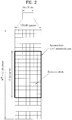
- FIG. 2 is a diagram illustrating a resource grid for one DL slot.
- a DL slot includes 7 OFDM symbols in the time domain and an RB includes 12 subcarriers in the frequency domain.
- a slot may include 7 OFDM symbols.
- a slot may include 6 OFDM symbols.
- Each element in the resource grid is referred to as a resource element (RE).
- An RB includes 12x7 REs.
- the number NDL of RBs included in a downlink slot depends on a DL transmission bandwidth.
- a UL slot may have the same structure as a DL slot.
- FIG. 3 illustrates a DL subframe structure. Up to the first three OFDM symbols of the first slot in a DL subframe are used as a control region to which control channels are allocated and the other OFDM symbols of the DL subframe are used as a data region to which a PDSCH is allocated.
- DL control channels used in 3GPP LTE include, for example, a physical control format indicator channel (PCFICH), a physical downlink control channel (PDCCH), and a physical hybrid automatic repeat request (HARQ) indicator channel (PHICH).
- PCFICH physical control format indicator channel
- PDCH physical downlink control channel
- HARQ physical hybrid automatic repeat request
- the PHICH carries a HARQ ACK/NACK signal in response to uplink transmission.
- Control information carried on the PDCCH is called downlink control information (DCI).
- the DCI includes UL or DL scheduling information or UL transmit power control commands for UE groups.
- the PDCCH delivers information about resource allocation and a transport format for a DL shared channel (DL-SCH), resource allocation information about a UL shared channel (UL-SCH), paging information of a paging channel (PCH), system information on the DL-SCH, information about resource allocation for a higher-layer control message such as a random access response transmitted on the PDSCH, a set of transmit power control commands for individual UEs of a UE group, transmit power control information, and voice over internet protocol (VoIP) activation information.
- a plurality of PDCCHs may be transmitted in the control region.
- a UE may monitor a plurality of PDCCHs.
- a PDCCH is formed by aggregating one or more consecutive control channel elements (CCEs).
- a CCE is a logical allocation unit used to provide a PDCCH at a coding rate based on the state of a radio channel.
- a CCE corresponds to a plurality of RE groups.
- the format of a PDCCH and the number of available bits for the PDCCH are determined depending on the correlation between the number of CCEs and a coding rate provided by the CCEs.
- An eNB determines the PDCCH format according to DCI transmitted to a UE and adds a cyclic redundancy check (CRC) to the control information.
- the CRC is masked by an identifier (ID) known as a radio network temporary identifier (RNTI) according to the owner or usage of the PDCCH.
- ID identifier
- RNTI radio network temporary identifier
- the PDCCH may be masked by a cell-RNTI (C-RNTI) of the UE. If the PDCCH is for a paging message, the CRC of the PDCCH may be masked by a paging radio network temporary identifier (P-RNTI). If the PDCCH delivers system information, particularly, a system information block (SIB), the CRC thereof may be masked by a system information ID and a system information RNTI (SI-RNTI). To indicate that the PDCCH delivers a random access response in response to a random access preamble transmitted by a UE, the CRC thereof may be masked by a random access-RNTI (RA-RNTI).
- SIB system information block
- SI-RNTI system information RNTI
- RA-RNTI random access-RNTI
- FIG. 4 illustrates a UL subframe structure.
- a UL subframe may be divided into a control region and a data region in the frequency domain.
- a physical uplink control channel (PUCCH) carrying uplink control information is allocated to the control region and a physical uplink shared channel (PUSCH) carrying user data is allocated to the data region.
- PUCCH physical uplink control channel
- PUSCH physical uplink shared channel
- a UE does not simultaneously transmit a PUSCH and a PUCCH.
- a PUCCH for a UE is allocated to an RB pair in a subframe. The RBs of the RB pair occupy different subcarriers in two slots. This is often called frequency hopping of the RB pair allocated to the PUCCH over a slot boundary.
- DCI formats 0, 1, 1A, 1B, 1C, 1D, 2, 2A, 2B, 2C, 3, 3A and 4 are defined in LTE-A (Release 10).
- DCI formats 0, 1A, 3 and 3A are defined to have the same message size to reduce the number of times of blind decoding, which will be described later.
- the DCI formats may be divided into i) DCI formats 0 and 4 used for uplink grant, ii) DCI formats 1, 1A, 1B, 1C, 1D, 2, 2A, 2B and 2C used for downlink scheduling allocation, and iii) DCI formats 3 and 3A for power control commands according to purposes of use of control information to be transmitted.
- DCI format 0 used for uplink grant may include a carrier indicator necessary for carrier aggregation, which will be described later, an offset (flag for format 0/format 1A differentiation) used to differentiate DCI formats 0 and 1A from each other, a frequency hopping flag that indicates whether frequency hopping is used for uplink PUSCH transmission, information about resource block assignment, used for a UE to transmit a PUSCH, a modulation and coding scheme, a new data indicator used to empty a buffer for initial transmission in relation to a HARQ process, a transmit power control (TPC) command for a scheduled PUSCH, information about a cyclic shift for a demodulation reference signal (DMRS) and OCC index, and a UL index and channel quality indicator request (CSI request) necessary for a TDD operation, etc.
- DCI format 0 does not include a redundancy version, unlike DCI formats relating to downlink scheduling allocation since DCI format 0 uses synchronous HARQ.
- the carrier indicator is not included in D
- DCI format 4 which is newly added to DCI formats in LTE-A Release 10, supports application of spatial multiplexing to uplink transmission in LTE-A.
- DCI format 4 has a larger message size DCI format 0 because it further includes information for spatial multiplexing.
- DCI format 4 includes additional control information in addition to control information included in DCI format 0. That is, DCI format 4 includes information on a modulation and coding scheme for the second transmission block, precoding information for multi-antenna transmission, and sounding reference signal (SRS) request information.
- SRS sounding reference signal
- DCI formats 1, 1A, 1B, 1C, 1D, 2, 2A, 2B and 2C for downlink scheduling allocation may be broadly divided into DCI formats 1, 1A, 1B, 1C and 1D, which do not support spatial multiplexing, and DCI formats 2, 2A, 2B and 2C, which support spatial multiplexing.
- DCI format 1C supports only frequency contiguous allocation as compact frequency allocation and does not include the carrier indicator and redundancy version, compared to the other formats.
- DCI format 1A is for downlink scheduling and random access.
- DCI format 1A may include a carrier indicator, an indicator that indicates whether downlink distributed transmission is used, PDSCH resource allocation information, a modulation and coding scheme, a redundancy version, a HARQ processor number for indicating a processor used for soft combining, a new data indicator used to empty a buffer for initial transmission in relation to a HARQ process, a TPC command for a PUCCH, an uplink index necessary for a TDD operation, etc.
- DCI format 1 includes control information similar to that of DCI format 1A.
- DCI format 1 supports non-contiguous resource allocation, while DCI format 1A is related to contiguous resource allocation. Accordingly, DCI format 1 further includes a resource allocation header, and thus slightly increases control signaling overhead as a trade-off for an increase in flexibility of resource allocation.
- Both DCI formats 1B and 1D further include precoding information, compared to DCI format 1.
- DCI format 1B includes PMI acknowledgement and DCI format 1D includes downlink power offset information.
- Most control information included in DCI formats 1B and 1D corresponds to that of DCI format 1A.
- DCI formats 2, 2A, 2B and 2C basically include most control information included in DCI format 1A and further include information for spatial multiplexing.
- the information for spatial multiplexing includes a modulation and coding scheme for the second transmission block, a new data indicator, and a redundancy version.
- DCI format 2 supports closed loop spatial multiplexing
- DCI format 2A supports open loop spatial multiplexing. Both DCI formats 2 and 2A include precoding information.
- DCI format 2B supports dual layer spatial multiplexing combined with beamforming and further includes cyclic shift information for a DMRS.
- DCI format 2C which may be regarded as an extended version of DCI format 2B, supports spatial multiplexing for up to 8 layers.
- DCI formats 3 and 3A may be used to complement the TPC information included in the aforementioned DCI formats for uplink grant and downlink scheduling allocation, namely, to support semi-persistent scheduling.
- a 1-bit command is used per UE in the case of DCI format 3
- a 2-bit command is used per UE in the case of DCI format 3A.
- One of the DCI formats described above is transmitted through a PDCCH, and a plurality of PDCCHs may be transmitted in a control region.
- a UE may monitor the plurality of PDCCHs.
- Control channel elements contiguous logical allocation units, are used to map a PDCCH to REs for efficient processing.
- a CCE includes a plurality of resource element groups (e.g., 9 REGs). Each REG includes four neighboring REs other than an RS.
- the number of CCEs necessary for a specific PDCCH depends on a DCI payload corresponding to a control information size, a cell bandwidth, a channel coding rate, etc. Specifically, the number of CCEs for a specific PDCCH may be defined according to PDCCH formats as shown in Table 1. Table 1 PDCCH format Number of CCEs Number of REGs Number of PDCCH bits 0 1 9 72 1 2 18 144 2 4 36 288 3 8 72 576
- one of the four formats may be used for a PDCCH and is not known to the UE. Accordingly, the UE performs decoding without knowing the PDCCH format. This is called blind decoding. Since operation overhead is generated if a UE decodes all the CCEs usable for downlink for each PDCCH, a search space is defined in consideration of restriction on a scheduler and the number of decoding attempts.
- the search space is a set of candidate PDCCHs composed of CCEs on which a UE needs to attempt to perform decoding at an aggregation level.
- Each aggregation level and the corresponding number of candidate PDCCHs may be defined as shown in Table 2.
- Table 2 Search space Number of PDCCH candidates Aggregation level Size (CCE unit) UE-specific 1 6 6 2 12 6 4 8 2 8 16 2 Common 4 16 4 8 16 2
- the UE has a plurality of search spaces at each aggregation level because 4 aggregation levels are present.
- the search spaces may be divided into a UE-specific search space and a common search space, as shown in Table 2.
- the UE-specific search space is for specific UEs.
- Each UE may check an RNTI and CRC which mask a PDCCH by monitoring a UE-specific search space thereof (attempting to decode a PDCCH candidate set according to an available DCI format) and acquire control information when the RNTI and CRC are valid.
- the common search space is used for a case in which a plurality of UEs or all UEs need to receive PDCCHs, for system information dynamic scheduling or paging messages, for example.
- the CSS may be used for a specific UE for resource management. Furthermore, the CSS may overlap the UE-specific search space.
- the control information for the UEs may be masked by one of RA-RNTI, SI-RNTI and P-RNTI.
- the search space may be determined by Equation 1 given below.
- L denotes an aggregation level
- Y k is a variable determined by an RNTI and subframe number k
- M ( L ) is the number of PDCCH candidates.
- N CCE is the total number of CCEs in the control region of a k-th subframe
- Y k is always determined to be 0.
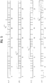
- FIG. 5 shows USSs (shaded portions) at respective aggregation levels which may be defined according to Equation 1. Carrier aggregation is not used, and N CCE, k is set to 32 for simplicity of illustration.
- FIGs. 5(a), 5(b), 5(c) and 5(d) illustrate the cases of aggregation levels 1, 2, 4 and 8, respectively.
- the numbers represent CCE numbers.
- the start CCE of a search space at each aggregation level is determined based on an RNTI and subframe number k. This CCE may be differently determined among the aggregations levels in the same subframe for a UE due to the modulo function and L. The CCE is always determined to correspond to a multiple of the aggregation level due to L.
- Y k is assumed to be CCE 18.
- the UE attempts to sequentially perform decoding from the start CCE in units of CCEs determined for a corresponding aggregation level.
- FIG. 5(b) for example, The UE attempts to perform decoding from CCE 4, the start CCE, for every two CCEs according to the aggregation levels.
- the UE attempts to perform decoding for a search space.
- the number of decoding attempts is determined by a DCI format and a transmission mode determined through radio resource control (RRC) signaling.
- RRC radio resource control
- the UE needs to attempt to perform decoding up to 12 times in a CSS, in consideration of two DCI sizes (DCI formats 0/1A/3/3A and DCI format 1C) for each of six PDCCH candidates.
- the maximum number of decodings increases because as many decodings for a USS and DCI format 4 as the number of DL resources (DL component carriers) are added.
- the packets are transmitted over a radio channel, and therefore signal distortion may occur in the transmission process.
- the received distorted signal should be corrected using channel information.
- a signal which is known to both the transmitter and the receiver is transmitted and the degree of distortion of the signal received over the channel is used to detect the channel information. This signal is referred to as a pilot signal or a reference signal.
- a channel state between a transmit antenna and a receive antenna needs to be identified to receive a correct signal. Accordingly, a separate RS is needed for each transmit antenna and, more particularly, for each antenna port.
- the RSs may be divided into a UL RS and a DL RS.
- the UL RSs include:
- the DL RSs include:
- the RSs may be broadly divided into two reference signals according to the purposes thereof. There are an RS used to acquire channel information and an RS used for data demodulation. Since the former is used when the UE acquires channel information on DL, this RS should be transmitted over a wide band and even a UE which does not receive DL data in a specific sub frame should receive the RS. This RS is also applied to situations such as handover.
- the latter RS is sent by the BS along with a resource on DL.
- the UE may receive the RS to perform channel measurement to implement data modulation. This RS should be transmitted in a region in which data is transmitted.
- the CRS is used for acquisition of channel information and for data demodulation, and the UE-specific RS is used only for data demodulation.
- the CRS is transmitted in every subframe in a wide band and RSs for up to four antenna ports are transmitted according to the number of transmit antennas of the BS.
- CRSs for antenna ports #0 and #1 are transmitted. If the number of transmit antennas of the BS is 4, CRSs for antenna ports #0 to #3 are respectively transmitted.
- FIG. 6 is a diagram illustrating a pattern in which CRSs and DRSs defined in a legacy 3GPP LTE system (e.g., Release-8) are mapped to resource block (RB) pairs.
- a downlink RB pair as a unit to which an RS is mapped, may be represented as a unit of one subframe in the time domain times 12 subcarriers in the frequency domain. That is, one RB pair has a length of 14 OFDM symbols for a normal CP ( FIG. 6(a) ) and a length of 12 OFDM symbols for an extended CP ( FIG. 6(b) ).
- FIG. 6 shows locations of RSs on RB pairs in a system in which the BS supports four transmit antennas.
- resource elements denoted by “0", “1", “2” and “3” represent the locations of the CRSs for antenna port indexes 0, 1, 2 and 3, respectively.
- REs denoted by “D” represent locations of the DMRSs.
- an enhanced-PDCCH (EPDCCH) is considered as a solution to lack of capacity of a PDCCH due to coordinated multi-point (CoMP), multi user-multiple input multiple output (MU-MIMO), and the like and degradation of PDCCH performance due to inter-cell interference.
- channel estimation may be performed on an EPDCCH based on DMRSs contrary to the existing CRS-based PDCCH, in order to obtain a pre-coding gain.
- transmission of the PDCCH described above is performed based on REGs and CCEs configured with REGs
- transmission of the EPDCCH may be performed based on enhanced REGs (EREGs), enhanced CCE (ECCEs), and physical resource block (PRB) pairs.
- EREGs enhanced REGs
- ECCEs enhanced CCE
- PRB physical resource block
- Each ECCE may include four EREGs
- each PRB pair may include four ECCEs.
- EPDCCH also employs the concept of aggregation level as in the case of PDCCH, but the aggregation levels for the EPDCCH are based on ECCEs.
- EPDCCH transmission may be divided into localized EPDCCH transmission and distributed EPDCCH transmission according to configuration of a PRB pair used for EPDCCH transmission.
- Localized EPDCCH transmission represents a case in which resource sets used for transmission of an EPDCCH neighbor each other in the frequency domain, and precoding may be applied to obtain a beamforming gain.
- localized EPDCCH transmission may be based on consecutive ECCEs the number of which corresponds to aggregation level.
- distributed EPDCCH transmission represents transmission of an EPDCCH in a separated PRB pair in the frequency domain, and has an advantage with regard to frequency diversity.
- distributed EPDCCH transmission may be based on the ECCE having four EREGs included in each PRB pair separated in the frequency domain.
- EPDCCH transmission may be divided into localized EPDCCH transmission and distributed EPDCCH transmission.
- a UE may configure a search space by distinguishing a resource set for localized EPDCCH transmission from a resource set for distributed EPDCCH transmission.
- the resource set may be as PRB set or an ECCE
- an eNB may indicate the transmission type (localized EPDCCH transmission or distributed EPDCCH transmission) of a resource set through higher layer signaling.
- the UE may perform blind decoding at each aggregation level on a resource unit for EPDCCH among a plurality of resource units of a subframe (for example, if the resource set is a PRB set, the resource units may be PRB pairs or ECCEs (EREGs) and if the resource set is an ECCE, the ECCE or EREG may be a resource unit).
- the resource set may be configured for any one of localized EPDCCH transmission or distributed EPDCCH transmission.
- FIGs. 7 and 8 it is assumed that the resource set is a PRB set, and the resource unit is an ECCE or a PRB pair. While the PRB set is illustrated as having two or four PRB pairs in FIGs. 7 and 8 , embodiments of the present invention are not limited thereto. Depending on configuration, the number of the PRB pairs of a PRB set may be set to 2, 4, 8, or the like. In FIGs. 7 and 8 , PRB pairs included in a distributed PRB set are illustrated as being consecutive on the frequency axis for simplicity of illustration. Accordingly, the PRB pair included in a distributed PRB set may be considered non-consecutive on the frequency axis.
- FIG. 7(a) illustrates a case in which one PRB set is configured for a UE
- FIG. 7(b) illustrates a case in which two PRB sets are configured for the UE.
- the UE may recognize, through higher layer signaling, that one PRB set for EPDCCH is provided, and four PRB pairs are for EPDCCH transmission among the other PRB pairs of a subframe.
- the UE may also recognize whether this PRB set is for localized EPDCCH transmission or for distributed EPDCCH transmission.
- the UE may determine an EPDCCH candidate at each aggregation level according to the transmission type (localized EPDCCH transmission or distributed EPDCCH transmission) and perform decoding.
- two PRB sets are configured for the UE. It may be indicated through higher layer signaling that one of the two PRB sets is a PRB set for localized EPDDCH (localized PRB set) and the other one is a PRB set for distributed EPDDCH (distributed PRB set).
- the UE may determine an EPDCCH candidate for each PRB set according to each transmission type and perform decoding.
- both PRB sets may be for localized (or distributed) EPDCCH.
- the PRBs included in the respective PRB sets may not be mutually exclusive.
- a PRB pair included in one PRB set may belong to another PRB pair.
- FIG. 8 the PRB set for localized EPDDCH transmission includes PRB pair #n to PRB pair #n+3, and the PRB set for distributed EPDDCH transmission includes RB pair #n-1 to PRB pair #n. That is, PRB pair #n is included both in the PRB set for localized EPDDCH transmission and the PRB set for distributed EPDCCH transmission.
- the UE may consider only at least one antenna port other than the antenna ports associated with distributed EPDCCH transmission as being valid on the overlapping PRB pair, among antenna ports associated with localized EPDCCH transmission. For example, if antenna ports 107 and 109 are associated with distributed EPDCCH, and antenna ports 107, 108, 109 and 110 are associated with localized EPDCCH, the UE may use only antenna ports 108 and 109 to perform blind decoding for the localized EPDCCH in the overlapping PRB pair. Alternatively, the UE may use only ports 108 and 109 to perform blind decoding for the localized EPDCCH.
- ports may be predefined or indicated through higher layer signaling such that a port used for ECCE indexes 0, 1, 2, and 3 of the corresponding PRB pair is fixed to port 108 (or 109), and ECCE indexes 0 and 1 use port 108, and ECCE indexes 2 and 3 use port 109.
- a possible pattern may be predefined, and an eNB may signal the index of the pattern.
- the pattern may be defined for a certain number of resource units and repeated for all the resource units.
- the pattern may be defined by a mapping table as shown in Table 3 below. Table 3 Resource type index 0 1 2 3 4 5 6 7 8 Transmission type L L L L D D L L L L
- L denotes localized EPDCCH transmission
- D denotes distributed EPDCCH transmission. If resource unit indexes of a search space which are set through higher layer signaling are 2, 3, 4, 5, 6, and 7, the UE may exclude a resource unit of a specific type from the search space based on the signaled indexes. The specific type may be determined by higher layer signaling. That is, if a resource unit for distributed EPDCCH transmission needs to be excluded, resource unit indexes of a search space configured by the UE may be determined to be 2, 3, 6, and 7.
- ECCEs constituting an EPDCCH candidate of aggregation level 2 include an ECCE for localized EPDCCH transmission and an ECCE for distributed EPDCCH transmission.
- the UE may perform blind decoding/search space configuration using the following methods.
- the UE may assume that ports for the ECCEs are different from each other although the ECCEs are in the same EPDCCH candidate. That is, decoding for the ECCE for distributed EPDCCH transmission may be performed using a PRB pair (or ECCE) for distributed EPDCCH transmission and a port defined for distributed EPDCCH transmission and then the result of decoding may be combined with a result of decoding for the ECCE for localized EPDCCH transmission (transmitted through port different from the port for distributed EPDCCH transmission) to perform blind decoding.
- a PRB pair or ECCE
- an EPDCCH candidate of aggregation level 2 for a localized EPDCCH includes an ECCE for localized EPDCCH transmission and an ECCE for distributed EPDCCH transmission, and decoding is performed in the manner that decoding results for the respective ECCEs are combined together. That is, decoding for one ECCE is performed through a port for the ECCE for localized EPDCCH transmission, and decoding for the other ECCE is performed through another port for the ECCE for distributed EPDCCH transmission. This may mean that precoding can be performed differently for each ECCE.
- blind decoding for the EPDCCH candidate may be skipped. That is, if an ECCE for localized EPDCCH transmission and an ECCE for distributed EPDCCH transmission included in one EPDCCH candidate overlap each other, the UE may recognize such overlap and not perform blind decoding for the EPDCCH candidate.
- blind decoding of an EPDCCH candidate may be performed only for an ECCE of a specific transmission type among the ECCEs belonging to the EPDCCH candidate.
- the transmission type (localized or distributed) to be used may be determined based on the priority or the number of ECCEs.
- an ECCE of a transmission type to be decoded may be predetermined or indicated through higher layer signaling.
- only the ECCEs of the specific transmission type may be used for EPDCCH candidate decoding if the aggregation level is greater than or equal to 4, or if the number of ECCEs of the specific transmission type is greater than the number of ECCEs of another transmission type.
- ECCEs of different transmission types may not be included in the same search space in the process of search space configuration for the UE. That is, a search space only for localized (or distributed) EPDCCH transmission may be signaled to the UE.
- the EPDCCH candidate of aggregation level 1 may be configured only with ECCEs of a specific transmission type.
- FIG. 10 a description will be given, with reference to FIG. 10 , of a method of EPDCCH candidate configuration and a decoding method for the case in which a resource set for localized EPDCCH transmission and a resource set for distributed EPDCCH transmission are present together in a PRB pair.
- FIG. 10 it is assumed that one PRB pair has eight EREGs for simplicity of illustration. However, this example may also be applied to a case which one PRB pair has 16 EREGs.
- an EPDCCH candidate of an aggregation level for localized EPDCCH transmission includes an EREG for distributed EPDCCH transmission
- the EPDCCH candidate may not be subjected to blind decoding.
- the EPDCCH candidate including EREG 4 to EREG 7 is not subjected to blind decoding.
- an EPDCCH candidate of an aggregation level for localized EPDCCH transmission includes an EREG for distributed EPDCCH transmission
- blind decodig for the EPDCCH candidate may be performed using only EREGs (or ECCEs) configured to be used for a localized EPDCCH. That is, blind decoding may be performed using only EREG 4 and EREG 5 in FIG. 10 . This may be regarded as execution of rate matching for EREG 6 and EREG 7.
- the start positions of EPDCCH candidates of different aggregation levels may be set to be different from each other.
- an offset may be applied to the start position of the EPDCCH candidate such that all the EREGs for a localized EPDCCH are contained in a PRB pair. That is, in FIG. 10 , if PRB pair 0 is for localized EPDCCH transmission, PRB pair 1 is for localized and distributed EPDCCH transmissions, PRB pair 3 is for localized EPDCCH transmission and EREG 6 and EREG 7 are for distributed EPDCCH transmission, an EPDCCH candidate positioned at PRB pair 1 may be shifted to PRB pair 2.
- an EPDCCH candidate is for localized EPDCCH, but includes a resource set (an ECCE or an EREG set) for distributed EPDCCH
- the EPDCCH candidate may be configured using the consecutive set indexes excluding the resource set. That is, in FIG. 10 , if all the PRB pairs are localized EPDCCH candidates of aggregation level 4, and EREGs 4, 5, 6, and 7 are configured to be used for distributed EPDCCH, resource sets included in the EPDCCH candidate may be determined to be EREGs 0, 1, 2, 3, 8, 9, 10, and 11.
- FIG. 11 illustrates an EPDCCH resource set and antenna port mapping according to one embodiment of the present invention.
- the antenna port is allocated by unit of one ECCE, two ECCEs, and four ECCEs. That is, the antenna port is mapped according to the aggregation levels.
- an EPDCCH may use one antenna port to ensure scheduling flexibility and reduce decoding time.
- a mapping relationship between the ECCEs and the port may be UE-specifically delivered using a predetermined value (which means that a specific resource determines the port. That is, a resource at a specific position is transmitted through a specific port), or through higher layer signaling.
- FIGs. 12 to 13 illustrate port allocation in the case in which localized EPDCCH transmission and distributed EPDCCH transmission are mixed in one PRB pair according to one embodiment of the present invention.
- FIG. 12 illustrates a scheme in which ports other than the port for distributed EPDCCH transmission are sequentially allocated to ECCEs for localized EPDCCH transmission.
- the ports for the ECCEs are implicitly or explicitly mapped in the order of indexes 7, 8, 9 and 10 in a PRB pair.
- FIG. 12(a) illustrates an example of implicit allocation, in which a port allocated to a specific ECCE in the PRB pair may be determined depending on the position of a resource constituting the ECCE. As the port is determined depending on the position of the ECCE in the implicit allocation, non-consecutive port allocation may be possible in each PRB pair. That is, as shown in FIG.
- port allocation when two or three ECCEs for distributed EPDCCH transmission are present in a PRB pair, port allocation may be implemented as ⁇ 7, 9, 10 ⁇ or ⁇ 7, 10 ⁇ .
- FIG. 12(b) illustrates another example of implicit allocation on the assumption that port 10 is for distributed EPDCCH transmission.
- port allocation for ECCEs for localized EPDCCH transmission may change depending on the positions of ECCES for distributed EPDCCH transmission and ports.
- FIG. 12(c) illustrates explicit allocation.
- Explicit allocation refers to a scheme in which a UE receives a port to be used for EPDCCH decoding through higher layer signaling.
- the UE may recognize, through higher layer signaling, that ports 7, 8, 9, and 10 are mapped to the ECCEs in this order, and allocate the ports other than the port for an ECCE for distributed EPDCCH transmission to ECCEs for localized EPDCCH transmission in the order signaled.
- FIG. 13 illustrates another example of implicit allocation and explicit allocation.
- a port used for distributed EPDCCH transmission represents use of a port corresponding to the position of a corresponding ECCE. If a plurality of ECCEs used for distributed EPDCCH transmission is present in a PRB pair, one of the ports allocated to the ECCE may be used as a port for distributed EPDCCH transmission.
- a mapping that the UE is employing may conflict with mapping of the unused transmission type (i.e., the case in which the UE knows the transmission scheme for the resource, but this scheme is not the transmission scheme in which the UE is currently performing blind decoding). For example, referring to FIG.
- port 7, 8, 9, and 10 are implicitly/explicitly allocated to the CCEs in a PRB pair in this order in a transmission mode that the UE is currently using, and the port used for the distributed transmission type that the UE does not use is port 7, the UE cannot use port 7 for the distributed transmission type.
- the following methods may be used.
- the ports may be sequentially allocated to the resources that the UE can use, except the antenna port for a transmission type that is not used by the UE. That is, as shown in FIG. 14(a) , the UE cannot use two resource sets in the middle of the ECCEs in a PRB pair, and thus cannot use port 7. Accordingly, the other ports (ports 8, 9, and 10) may be sequentially allocated to the other resource sets.
- sequential allocation means mapping is performed according to the order of indexes of the ECCEs for EPDCCH in a PRB pair.
- the UE may allocate ports of a code division multiplexing (CDM) group to which a port used for the different transmission type does not belong first, among the ports usable by the UE.
- CDM code division multiplexing
- ports of the CDM group having the port of the transmission type which is not employed by the UE have lower priority in relation to port reallocation. That is, in FIG. 14 , sine the port used for distributed EPDCCH transmission is port 7, ports 9 and 10 belonging to a CDM group different from that of port 7 may be allocated first. Alternatively, ports of the other CDM group may be allocated, and then the remaining ports of the CDM group including the port used for the distributed type may be allocated. For example, if the port used for the distributed type is 8, and ECCE index is #1, antenna ports 7, 9, and 10 or antenna ports 9, 10, and 7 maybe allocated to ECCE indexes #0, #2, and #3.
- the UE may configure a search space based on the port mapping determined in the above two methods. At this time, the port/resource related to the transmission type that the UE does not employ may be excluded from the search space.
- DMRS configuration for the transmission type that is not used by the UE may employ a predefined mapping rule or be indicated for the UE through higher layer signaling.
- both resources and ports in the descriptions given above are restricted, but it is possible to apply restriction only to the ports. That is, in FIG. 14 , the UE may reallocate ports to all the resource sets in the PRB pair. In this case, ports may be determined to be used except the port of a transmission type that the UE does not use.
- the number of ports for each PRB pair may be determined according to the number of PRB pairs on which EPDCCH transmission is performed and the EPDCCH candidates of aggregation level 1 (or the number of blind decodings). Further, to enhance the effect of spatial diversity, when two or more EPDCCH candidates of the same level (e.g., aggregation levels 1 and 2 in localized EPDCCH transmission) are present within a PRB pair, blind decoding may be performed using different ports for the EPDCCH candidates.
- the antenna port numbers used on the PRB pair i.e., antenna ports used on the PRB pair
- the number of ports for each PRB pair used for EPDCCH transmission by each UE may be expressed as N+M in Equation 2 given below.
- N denotes the number of antenna ports that all the PRB pairs configured for EPDCCH transmission for a UE have in common
- i denotes the number of EPDCCH candidates (or the number of blind decodings) for aggregation level 1
- j denotes the number of PRB pairs configured through higher layer signaling
- P denote a PRB pair set configured for EPDCCH transmission.
- the value of M for each configured PRB pair may be determined to be 0 or 1
- the sum of values of M for all the configured PRB pairs equals the remainder obtained by dividing the number of EPDCCH candidates of aggregation level 1 by the number of configured PRB pairs.
- Equation 2 if the denominator is greater than the numerator, it may be assumed that the UE uses only one antenna port for all the PRB pairs.
- the value of M for the respective PRB pairs may be determined according to a defined rule (e.g., the value is set to 1 from the lowest PRB pair index).
- FIG. 15 illustrates an example of determining the number of antenna ports for each PRB pair according to Equation 2 described above.
- the example assumes that the values of M for the PRB pairs are sequentially allocated from the lowest PRB pair index, and that i, the number of EPDCCH candidates of aggregation level 1, is 6, and j, the number of PRB pairs for EPDCCH configured for the UE, is set to 6, 5, 4, 3, and 2.
- M may be set using a scheme different from the scheme of setting M to 1 from the lowest PRB pair index, such as a scheme of distributing the values of M with the values equally spaced in a given PRB pair or a scheme of setting the value from a specific PRB pair.
- the number of ports may be determined to be 2, 1, 2, and 1 for the respective PRB pairs (in this case, N is set to 1, 1, 1, and 1, and M is set to 1, 0, 1, and 0 for the respective PRB pairs).
- a PDSCH is not transmitted on a PRB pair on which an EPDCCH is transmitted, and the number of the resources available on the PRB pair is greater than that of the resources necessary for EPDCCH transmission. Accordingly, multiple EPDCCHs are preferably transmitted on one PRB pair.
- the search space allocation by the UE may significantly affect the EPDCCH demodulation performance. For example, as shown in FIG. 16 , when the position of each EPDCCH candidate is determined, EPDCCH decoding performance may significantly change depending on channel conditions. More specifically, in FIG. 16 , EPDCCH candidates for each aggregation level are consecutively positioned on the frequency axis. In this case, if a specific frequency band in which EPDCCH candidates for a UE are concentrated is subjected to, for example, deep fading, the EPDCCH demodulation performance of the UE may be greatly degraded.
- Another situation to be considered for allocation of an EPDCCH search space is a case in which two EPDCCHs are transmitted to the UE within a subframe. That is, an EPDCCH for DL grant and an EPDCCH for UL grant may be transmitted respectively. Preferably, such EPDCCHs are transmitted on the same PRB pair for beamforming gain.
- a search space is configured according to the following rules, considering the above discussion.
- PRB pairs constituting a search space for a UE are split and allocated in the frequency domain.
- the position of EPDCCH candidates corresponding to aggregation level 1 is restricted to two ECCEs per PRB pair.
- the ECCEs to be used as the position of the EPDCCH candidates for the UE may be indicated for the UE through RRC signaling.
- the search space is signaled PRB pair by PRB pair in indicating the search space through RRC signaling, and the position of the EPDCCH candidates on each PRB pair may be configured according to a predefined rule.
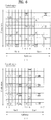
- FIG. 17 An example of search space configuration according to the rules described above is illustrated in FIG. 17 .
- ECCE to port mapping for each PRB pair uses a combination of ⁇ 7, 8, 9, 10 ⁇ and that the number of blind decodings for aggregation levels 1, 2 and 4 are 8, 8, and 2, respectively.
- This assumption is for simplicity of illustration, and there may be various examples complying with the above rules regardless of aggregation levels and the number of blind decodings.
- the number for the position of EPDCCH candidates for each aggregation level corresponds to an antenna port for demodulation of the EPDCCH.
- EPDCCH channel estimation for each PRB pair is completed when it is performed once or twice at all aggregation levels. Accordingly, when the rules described above are followed, configuration of the search space may be implemented with the minimized number of channel estimations.
- the example of FIG. 17 may also be embodied in the following manner.
- the port for each EPDCCH candidate may be configured through a combination of signaling of resource (e.g., ECCE)-to-port mapping and signaling of the search space definition.
- resource e.g., ECCE
- a pattern of the same port mapping (for example, mapping, when four ECCEs are present in each PRB pair and indexed as 0, 1, 2, and 3 in each PRB pair, ECCE0 to port 7, ECCE1 to port 8, ECCE2 to port 9, and ECCE3 to port 10) may be signaled on all PRB pairs (e.g., PRB pairs on which EPDCCH is transmitted), or a different pattern of port mapping may be signaled for each PRB pair.
- the search space definition refers to a process of indicating, by an eNB, EPDCCH candidates for which the UE needs to perform blind decoding.
- the EPDCCH candidates for each aggregation level may be indicated for the UE by applying the aforementioned rule which prescribes that EPDCCH candidates of aggregation level 1 are restricted to two ECCEs per PRB pair configured for EPDCCH transmission.
- ports for the respective EPDCCH candidates may be defined in conjunction with the independently signaled port mapping. For an EPDCCH candidate of an aggregation level higher than or equal to 2, one of the ports for aggregation level 1 EPDCCH candidates (or ECCEs if aggregation level 1 EPDCCH candidates are not included) constituting the EPDCCH candidate may be selected.
- a description will be given of a method of determining a DMRS port that the UE uses in detecting an EPDCCH (i.e., ECCE to port mapping). Specifically, a description will be given of a method of mapping between a resource set (e.g., an ECCE) on which EPDCCH is transmitted and a DMRS port for EPDCCH demodulation and a method for signaling the mapping.
- a resource set e.g., an ECCE
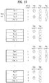
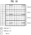
- each PRB pair has four ECCEs as shown in FIG. 18 .
- the first method is to configure a port combination table and signal the indexes of the port combinations such that a port combination corresponding to an index is used for each of the PRB pairs. That is, all combinations of four RS ports may be listed to map an antenna port to each ECCE, and the network may indicate indexes of UE-specific or cell-specific RS port combinations through higher layer signaling. In this case, an MU-MIMO-based EPDCCH may be implemented, and inter-cell RS collision may be avoided. An example of the indexes of the combinations is shown in FIG. 4 .
- the second method which is based on the first method, is to signal an index for each PRB pair. 5 bits are needed to implement such signaling, but some of the combinations may be eliminated to lower signaling overhead.
- antenna ports for consecutive ECCEs may belong to different CDM groups. That is, only combinations such as ⁇ 7, 9, 8, 10 ⁇ and ⁇ 9, 7, 10, 8 ⁇ may be considered. In the case in which these combinations are used, RS collision between ECCEs using the same time/frequency resources may be avoided when neighboring cells use the same time/frequency resources for EPDCCH transmission.
- the combinations described above are configured such that ECCEs constituting a PRB pair use different ports, but the table may include a case in which consecutive ECCEs use the same port. That is, patterns such as ⁇ 7, 7, 9, 9 ⁇ , ⁇ 8, 8, 10, 10 ⁇ , ⁇ 7, 7, 8, 8 ⁇ , ⁇ 9, 9, 10, 10 ⁇ , ⁇ 7, 7, 7, 7 ⁇ , and ⁇ 8, 8, 8, 8 ⁇ may be added to Table 4. These patterns may be implemented in the form of ⁇ a, a, b, b ⁇ , ⁇ a, b, b, b ⁇ , ⁇ a, a, b ⁇ , ⁇ a, b, b, a ⁇ , and ⁇ a, a, a, a ⁇ .
- the combinations may be useful when the ECCEs having the same port are used at different transmission points.
- virtual cell IDs may be grouped, and one of the patterns may be used in each group.
- the third method is to link results of modulo operation for the virtual cell IDs to the aforementioned indexes. In other words, this method is to tie the indexes to another parameter signaled for an EPDCCH RS.
- a scrambling sequence for a DMRS may be derived from Equation 3 given below.
- c init ⁇ n s 2 ⁇ + 1 ⁇ 2 X + 1 ⁇ 2 16 + n SCID
- Equation 3 X and n SCID may be contained and signaled in the DCI format. Equation 3 may be used even for an EPDCCH DMRS. However, in the case of EPDCCH, use of the DCI format is not allowed, and thus n SCID may be fixed to a specific value, and parameter X may be indicated through RRC signaling. Accordingly, modulo operation may be performed for parameter X signaled for the DMRS scrambling sequence to derive an index in an ECCE-to-port mapping table. Specifically, for example, if the ECCE-to-port mapping table is given as Table 4, the UE may determine the DMRS scrambling sequence index through modulo operation (X modulo 24).
- FIG. 19 is a diagram illustrating configurations of a transmission point apparatus and a UE according to one embodiment of the present invention.
- a transmission point apparatus 1910 may include a receive module 1911, a transmit module 1912, a processor 1913, a memory 1914, and a plurality of antennas 1915.
- the antennas 1915 represent a transmission point apparatus that supports MIMO transmission and reception.
- the receive module 1911 may receive various signals, data and information from a UE on uplink.
- the transmit module 1912 may transmit various signals, data and information to a UE on downlink.
- the processor 1913 may control overall operation of the transmission point apparatus 1910.
- the processor 1913 of the transmission point apparatus 1910 may perform operations necessary for the embodiments described above.
- the processor 1913 of the transmission point apparatus 1910 may function to operationally process information received by the transmission point apparatus 1910 or information to be transmitted to the outside, etc.
- the memory 1914 which may be replaced with an element such as a buffer (not shown), may store the processed information for a predetermined time.
- a UE 1920 may include a receive module 1921, a transmit module 1922, a processor 1923, a memory 1924, and a plurality of antennas 1925.
- the antennas 1925 mean that the UE supports MIMO transmission and reception.
- the receive module 1921 may receive various signals, data and information from an eNB on downlink.
- the transmit module 1922 may transmit various signals, data and information to the eNB on uplink.
- the processor 1923 may control overall operation of the UE 1920.
- the processor 1923 of the UE 1920 may perform operations necessary for the embodiments described above.
- the processor 1923 may function to operationally process information received by the UE 1920 or information to be transmitted to the outside, and the memory 1924, which may be replaced with an element such as a buffer (not shown), may store the processed information for a predetermined time.
- the configurations of the transmission point apparatus and the UE as described above may be implemented such that the above-described embodiments are independently applied or two or more thereof are simultaneously applied, and description of redundant parts is omitted for clarity.
- Description of the transmission point apparatus 1910 in FIG. 19 may also be applied to a relay which serves as a downlink transmitter or an uplink receiver, and description of the UE 1920 may be applied to a relay which serves as a downlink receiver or an uplink transmitter.
- the embodiments of the present invention may be implemented through various means, for example, hardware, firmware, software, or a combination thereof.
- a method according to embodiments of the present invention may be embodied as one or more application specific integrated circuits (ASICs), one or more digital signal processors (DSPs), one or more digital signal processing devices (DSPDs), one or more programmable logic devices (PLDs), one or more field programmable gate arrays (FPGAs), a processor, a controller, a microcontroller, a microprocessor, etc.
- ASICs application specific integrated circuits
- DSPs digital signal processors
- DSPDs digital signal processing devices
- PLDs programmable logic devices
- FPGAs field programmable gate arrays
- processor a controller, a microcontroller, a microprocessor, etc.
- a method according to embodiments of the present invention may be embodied as a module, a procedure, or a function that performs the functions or operations described above.
- Software code may be stored in a memory unit and executed by a processor.
- the memory unit is located at the interior or exterior of the processor and may transmit and receive data to and from the processor via various known means.
Claims (9)
- Procédé de réception d'informations de commande par un équipement utilisateur, UE, (1920) dans un système de communication sans fil, comprenant :réaliser un décodage aveugle sur une pluralité de paires de blocs de ressources physiques, PRB, dans chacun d'au moins un ensemble de PRB d'EPDCCH par utilisation d'un signal de référence de démodulation, DMRS, d'EPDCCH,dans lequel,chacune de la pluralité de paires de PRB comprend quatre éléments de canal de commande améliorés, ECCE,une séquence d'embrouillage pour le DMRS d'EPDCCH est obtenue sur la base d'une équation '([nS/2]+1)·(2X+1)·216+nSCID', où 'ns' désigne un nombre de créneaux,un paramètre de séquence d'embrouillage 'X' pour le DMRS d'EPDCCH est signalé à l'UE par l'intermédiaire d'une signalisation RRC, etune identité d'embrouillage 'nSCID' pour le DMRS d'EPDCCH est fixée à une valeur spécifique,caractérisé par le fait que :
l'UE détermine un port d'antenne pour chacun des quatre ECCE, par détermination d'un indice dans une table de mappage d'ECCE à port par réalisation d'une opération de modulo pour le paramètre de séquence d'embrouillage 'X' avec le nombre d'indices dans la table de mappage d'ECCE à port. - Procédé selon la revendication 1, dans lequel des informations indiquant que chacun de l'au moins un ensemble de PRB d'EPDCCH est configuré soit pour une émission d'EPDCCH localisée, soit pour une émission d'EPDCCH distribuée sont signalées à l'UE par l'intermédiaire d'une signalisation de couche supérieure.
- Procédé selon la revendication 1, dans lequel la détermination des paires de PRB pour l'EPDCCH est basée sur des informations concernant un ensemble de PRB délivré par l'intermédiaire d'une signalisation de couche supérieure.
- Procédé selon la revendication 1, dans lequel :l'au moins un ensemble de PRB d'EPDCCH comprend un premier ensemble de PRB configuré pour une émission d'EPDCCH localisée et un second ensemble de PRB configuré pour une émission d'EPDCCH distribuée ; etlorsqu'une paire de PRB chevauchante incluse à la fois dans les premier et second ensembles de PRB est présente parmi les paires de PRB pour l'EPDCCH, l'UE considère au moins un port d'antenne associé à l'émission d'EPDCCH localisée autre qu'au moins un port d'antenne associé à l'émission d'EPDCCH distribuée comme valide sur la paire de PRB chevauchante.
- Procédé selon la revendication 4, dans lequel l'au moins un port d'antenne associé à l'émission d'EPDCCH localisée comprend des ports d'antenne 107, 108, 109 et 110, et l'au moins un port d'antenne associé à l'émission d'EPDCCH distribuée comprend des ports d'antenne 107 et 109.
- Procédé selon la revendication 1, dans lequel chacun des ECCE comprend quatre groupes d'éléments de ressources améliorés, EREG.
- Procédé selon la revendication 6, dans lequel l'émission d'EPDCCH localisée est basée sur au moins un ECCE consécutif selon un niveau d'agrégation.
- Procédé selon la revendication 6, dans lequel l'émission d'EPDCCH distribuée est basée sur un ECCE comprenant des EREG appartenant à des paires de PRB.
- Equipement utilisateur (1920) dans un système de communication sans fil, comprenant :un module de réception (1921) ; etun processeur (1923),le processeur (1923) étant configuré pour réaliser un décodage aveugle sur une pluralité de paires de blocs de ressources physiques, PRB, dans chacun d'au moins un ensemble de PRB d'EPDCCH par utilisation d'un signal de référence de démodulation, DMRS, d'EPDCCH,dans lequel,chacune de la pluralité de paires de PRB comprend quatre éléments de canal de commande améliorés, ECCE,une séquence d'embrouillage pour le DMRS d'EPDCCH est obtenue sur la base d'une équation '([nS/2]+1)·(2X+1)·216nSCID', où 'ns' désigne un nombre de créneaux,un paramètre de séquence d'embrouillage 'X ' pour le DMRS d'EPDCCH est signalé à l'UE par l'intermédiaire d'une signalisation RRC, etune identité d'embrouillage 'nSCID' pour le DMRS d'EPDCCH est fixée à une valeur spécifique,caractérisé par le fait que :
le processeur est configuré pour déterminer un port d'antenne pour chacun des quatre ECCE, par détermination d'un indice dans une table de mappage d'ECCE à port par réalisation d'une opération de modulo pour le paramètre de séquence d'embrouillage 'X' avec le nombre d'indices dans la table de mappage d'ECCE à port.
Applications Claiming Priority (6)
| Application Number | Priority Date | Filing Date | Title |
|---|---|---|---|
| US201261614495P | 2012-03-22 | 2012-03-22 | |
| US201261617032P | 2012-03-28 | 2012-03-28 | |
| US201261617673P | 2012-03-30 | 2012-03-30 | |
| US201261621001P | 2012-04-06 | 2012-04-06 | |
| US201261682743P | 2012-08-13 | 2012-08-13 | |
| PCT/KR2013/002407 WO2013141654A1 (fr) | 2012-03-22 | 2013-03-22 | Procédé et appareil de réception d'informations de commande dans un système de communication sans fil |
Publications (3)
| Publication Number | Publication Date |
|---|---|
| EP2830244A1 EP2830244A1 (fr) | 2015-01-28 |
| EP2830244A4 EP2830244A4 (fr) | 2015-12-02 |
| EP2830244B1 true EP2830244B1 (fr) | 2019-05-08 |
Family
ID=49631218
Family Applications (1)
| Application Number | Title | Priority Date | Filing Date |
|---|---|---|---|
| EP13764508.1A Active EP2830244B1 (fr) | 2012-03-22 | 2013-03-22 | Procédé et appareil de réception d'informations de commande dans un système de communication sans fil |
Country Status (6)
| Country | Link |
|---|---|
| US (3) | US9445413B2 (fr) |
| EP (1) | EP2830244B1 (fr) |
| JP (2) | JP6110472B2 (fr) |
| KR (1) | KR102078366B1 (fr) |
| CN (1) | CN104205685B (fr) |
| WO (1) | WO2013141654A1 (fr) |
Families Citing this family (21)
| Publication number | Priority date | Publication date | Assignee | Title |
|---|---|---|---|---|
| CN103947249B (zh) * | 2011-09-30 | 2018-04-27 | 英特尔公司 | 通过多个无线网络同时地传送因特网业务的方法 |
| EP2830244B1 (fr) | 2012-03-22 | 2019-05-08 | LG Electronics Inc. | Procédé et appareil de réception d'informations de commande dans un système de communication sans fil |
| KR101709598B1 (ko) * | 2012-09-14 | 2017-02-23 | 후아웨이 디바이스 컴퍼니 리미티드 | 인핸스트 다운링크 제어 채널 자원과 안테나 포트 간의 맵핑을 구축하기 위한 방법 및 장치 |
| KR102130353B1 (ko) * | 2012-09-18 | 2020-07-06 | 삼성전자주식회사 | 통신 시스템에서 제어 채널 자원 구성 방법 및 장치 |
| CN104854904B (zh) * | 2013-10-25 | 2019-06-21 | 华为技术有限公司 | 数据调度方法和装置 |
| US20160270038A1 (en) * | 2015-03-11 | 2016-09-15 | Samsung Electronics Co., Ltd | Transmissions of downlink control channels for low cost ues |
| US10111216B2 (en) * | 2015-04-02 | 2018-10-23 | Qualcomm Incorporated | Reducing blind decoding in enhanced carrier aggregation |
| US10382107B2 (en) * | 2015-08-12 | 2019-08-13 | Intel Corporation | Multi-user multiple input multiple output communication systems and methods |
| WO2017123286A1 (fr) | 2016-01-11 | 2017-07-20 | Intel IP Corporation | Appareil et procédé pour canal de commande d'iot |
| CN108604946A (zh) | 2016-02-09 | 2018-09-28 | 瑞典爱立信有限公司 | 高效的harq反馈 |
| KR102521728B1 (ko) | 2016-08-19 | 2023-04-14 | 삼성전자 주식회사 | 이동 통신 시스템에서의 채널 상태 정보 수신 방법 및 장치 |
| US10476647B2 (en) | 2016-10-25 | 2019-11-12 | Qualcomm Incorporated | Coherence based pre-decoding pruning for control channel processing |
| CN108809505B (zh) * | 2017-05-05 | 2019-12-24 | 维沃移动通信有限公司 | 下行控制信息的传输方法、终端及网络侧设备 |
| WO2018227337A1 (fr) * | 2017-06-12 | 2018-12-20 | Qualcomm Incorporated | Techniques et appareils de signalisation concernant une taille de commande dépendant de la largeur de bande |
| CN109150387B (zh) * | 2017-06-16 | 2023-04-28 | 华为技术有限公司 | 发送参考信号的方法、接收参考信号的方法和通信装置 |
| CN110892766B (zh) * | 2017-07-03 | 2022-12-27 | 上海朗帛通信技术有限公司 | 一种被用于多天线通信的用户设备、基站中的方法和装置 |
| KR102424636B1 (ko) | 2017-09-30 | 2022-07-22 | 광동 오포 모바일 텔레커뮤니케이션즈 코포레이션 리미티드 | 채널 자원의 지시 방법, 단말 기기 및 네트워크 기기 |
| EP3468061A1 (fr) | 2017-10-03 | 2019-04-10 | Panasonic Intellectual Property Corporation of America | Aspects de signalisation pour indication de ports de dmrs co-planifiés en mu-mimo |
| CN109699054B (zh) * | 2017-10-24 | 2020-11-06 | 华为技术有限公司 | 一种检测下行控制信息的方法、终端设备和网络设备 |
| RU2750435C1 (ru) | 2017-11-14 | 2021-06-28 | Идак Холдингз, Инк. | Способы определения кандидата физического канала управления нисходящей линии связи (pdcch) |
| US20220416993A1 (en) * | 2021-06-23 | 2022-12-29 | Qualcomm Incorporated | Demodulator configuration based on user equipment signaling |
Family Cites Families (21)
| Publication number | Priority date | Publication date | Assignee | Title |
|---|---|---|---|---|
| WO2010053984A2 (fr) * | 2008-11-04 | 2010-05-14 | Nortel Networks Limited | Établissement de structure de commande de liaison descendante dans une première porteuse pour indiquer une information de commande dans une seconde porteuse différente |
| CN102246553A (zh) * | 2008-12-15 | 2011-11-16 | 诺基亚公司 | 用于扩展的带宽系统的下行链路控制和物理混合arq指示符信道(phich)配置 |
| US8565260B2 (en) * | 2009-04-13 | 2013-10-22 | Lg Electronics Inc. | Method and apparatus for transmitting system information from a base station supporting an improved system |
| US8965273B2 (en) | 2009-09-21 | 2015-02-24 | Lg Electronics Inc. | Repeater for receiving signals from a base station in a wireless communication system, and signal receiving method |
| KR101915271B1 (ko) * | 2010-03-26 | 2018-11-06 | 삼성전자 주식회사 | 무선 통신 시스템에서 자원 할당을 위한 하향링크 제어 지시 방법 및 장치 |
| KR101684867B1 (ko) | 2010-04-07 | 2016-12-09 | 삼성전자주식회사 | 공간 다중화 이득을 이용한 제어 정보 송수신 방법 |
| KR101673906B1 (ko) | 2010-04-29 | 2016-11-22 | 삼성전자주식회사 | Ofdm 시스템에서 공간 다중화 제어 채널 지원을 위한 상향 링크 ack/nack 채널의 맵핑 방법 및 장치 |
| KR101770571B1 (ko) * | 2010-06-28 | 2017-09-06 | 엘지전자 주식회사 | 다중 노드 시스템에서 동기화 신호 전송 방법 및 장치 |
| DK2919545T3 (en) * | 2011-02-11 | 2016-12-05 | Interdigital Patent Holdings Inc | Device and method for an improved control channel (E-PDCCH). |
| US20130288686A1 (en) * | 2011-04-29 | 2013-10-31 | Joey Chou | Techniques to manage energy savings for interoperable radio access technology networks |
| US8917679B2 (en) * | 2011-08-16 | 2014-12-23 | Nokia Corporation | Method for signaling the overlap of downlink control and data channels |
| CN102316595B (zh) * | 2011-09-30 | 2017-04-12 | 中兴通讯股份有限公司 | 大带宽系统物理上行控制信道资源确定方法及装置 |
| US9166729B2 (en) * | 2011-12-14 | 2015-10-20 | Marvell World Trade Ltd. | Enhanced demodulation reference signal (DM-RS) design |
| US9769806B2 (en) * | 2012-01-17 | 2017-09-19 | Texas Instruments Incorporated | Resource configuration for EPDCCH |
| US9179456B2 (en) * | 2012-02-07 | 2015-11-03 | Samsung Electronics Co., Ltd. | Methods and apparatus for downlink control channels transmissions in wireless communications systems |
| US9924498B2 (en) * | 2012-03-12 | 2018-03-20 | Qualcomm Incorporated | Selecting a cell identifier based on a downlink control information |
| US9167561B2 (en) * | 2012-03-12 | 2015-10-20 | Zte (Usa) Inc. | Sequence initialization for demodulation reference signal |
| US9445409B2 (en) * | 2012-03-21 | 2016-09-13 | Mediatek, Inc. | Method for search space configuration of enhanced physical downlink control channel |
| EP2830244B1 (fr) | 2012-03-22 | 2019-05-08 | LG Electronics Inc. | Procédé et appareil de réception d'informations de commande dans un système de communication sans fil |
| US9167574B2 (en) * | 2012-09-28 | 2015-10-20 | Intel Corporation | Blind decoding for an enhanced physical downlink control channel (EPDCCH) |
| US8923880B2 (en) * | 2012-09-28 | 2014-12-30 | Intel Corporation | Selective joinder of user equipment with wireless cell |
-
2013
- 2013-03-22 EP EP13764508.1A patent/EP2830244B1/fr active Active
- 2013-03-22 JP JP2015501585A patent/JP6110472B2/ja active Active
- 2013-03-22 CN CN201380015741.0A patent/CN104205685B/zh active Active
- 2013-03-22 KR KR1020130030996A patent/KR102078366B1/ko active IP Right Grant
- 2013-03-22 US US14/384,142 patent/US9445413B2/en active Active
- 2013-03-22 WO PCT/KR2013/002407 patent/WO2013141654A1/fr active Application Filing
-
2016
- 2016-07-13 US US15/209,451 patent/US9615365B2/en active Active
-
2017
- 2017-01-24 US US15/414,245 patent/US10028266B2/en active Active
- 2017-03-08 JP JP2017043831A patent/JP2017127014A/ja active Pending
Non-Patent Citations (3)
| Title |
|---|
| RENESAS MOBILE EUROPE LTD: "On ePDCCH search spaces", 3GPP DRAFT; R1-120383, 3RD GENERATION PARTNERSHIP PROJECT (3GPP), MOBILE COMPETENCE CENTRE ; 650, ROUTE DES LUCIOLES ; F-06921 SOPHIA-ANTIPOLIS CEDEX ; FRANCE, vol. RAN WG1, no. Dresden, Germany; 20120206 - 20120210, 1 February 2012 (2012-02-01), XP050563209 * |
| RENESAS MOBILE EUROPE LTD: "Reference signals for ePDCCH", 3GPP DRAFT; R1-121396, 3RD GENERATION PARTNERSHIP PROJECT (3GPP), MOBILE COMPETENCE CENTRE ; 650, ROUTE DES LUCIOLES ; F-06921 SOPHIA-ANTIPOLIS CEDEX ; FRANCE, vol. RAN WG1, no. Jeju, Korea; 20120326 - 20120330, 20 March 2012 (2012-03-20), XP050599683 * |
| ZTE: "Discussion on DMRS for enhanced PDCCH", 3GPP DRAFT; R1-121051 DISCUSSION ON DMRS FOR ENHANCED PDCCH, 3RD GENERATION PARTNERSHIP PROJECT (3GPP), MOBILE COMPETENCE CENTRE ; 650, ROUTE DES LUCIOLES ; F-06921 SOPHIA-ANTIPOLIS CEDEX ; FRANCE, vol. RAN WG1, no. Jeju, Korea, 20 March 2012 (2012-03-20), XP050599354 * |
Also Published As
| Publication number | Publication date |
|---|---|
| EP2830244A1 (fr) | 2015-01-28 |
| JP2015516729A (ja) | 2015-06-11 |
| CN104205685A (zh) | 2014-12-10 |
| US20160323858A1 (en) | 2016-11-03 |
| CN104205685B (zh) | 2017-08-08 |
| WO2013141654A1 (fr) | 2013-09-26 |
| US9445413B2 (en) | 2016-09-13 |
| JP2017127014A (ja) | 2017-07-20 |
| KR20130108192A (ko) | 2013-10-02 |
| US9615365B2 (en) | 2017-04-04 |
| JP6110472B2 (ja) | 2017-04-05 |
| EP2830244A4 (fr) | 2015-12-02 |
| US20170135083A1 (en) | 2017-05-11 |
| US10028266B2 (en) | 2018-07-17 |
| KR102078366B1 (ko) | 2020-04-07 |
| US20150063236A1 (en) | 2015-03-05 |
Similar Documents
| Publication | Publication Date | Title |
|---|---|---|
| US10028266B2 (en) | Method and apparatus for receiving control information through blind decoding of an enhanced physical downlink control channel (EPDCCH) | |
| US10694513B2 (en) | Method and apparatus for transmitting control information in wireless communication system | |
| US9565667B2 (en) | Method and device for receiving downlink signal in wireless communication system | |
| US9590786B2 (en) | Method and apparatus for transmitting acknowledgement in wireless communication system | |
| EP3016302A1 (fr) | Procédé et appareil d'acquisition d'informations de commande dans un système de communication sans fil | |
| US9867173B2 (en) | Method and apparatus for receiving downlink signal in wireless communication system | |
| US9549400B2 (en) | Method and apparatus for receiving control information in wireless communication system | |
| US9769815B2 (en) | Method and apparatus for receiving downlink signal in wireless communication system | |
| US10334579B2 (en) | Method and device for receiving control information in wireless communication system | |
| EP2897435B1 (fr) | Procédé et appareil de réception de signal de liaison descendante dans un système de communication sans fil | |
| US9750036B2 (en) | Method and apparatus for receiving downlink signals in wireless communication system | |
| US9848441B2 (en) | Method and apparatus for receiving downlink control information through an enhanced physical downlink control channel in wireless communication | |
| US9730243B2 (en) | Method and device for transmitting uplink signal in wireless communication system | |
| US20140314038A1 (en) | Method and apparatus for transmitting control information in a wireless communication system | |
| US9660783B2 (en) | Method and device for receiving control information in wireless communication system | |
| US9768926B2 (en) | Method and apparatus for receiving control information in wireless communication system | |
| US9246538B2 (en) | Method and device for decoding signal in wireless communication system |
Legal Events
| Date | Code | Title | Description |
|---|---|---|---|
| PUAI | Public reference made under article 153(3) epc to a published international application that has entered the european phase |
Free format text: ORIGINAL CODE: 0009012 |
|
| 17P | Request for examination filed |
Effective date: 20140925 |
|
| AK | Designated contracting states |
Kind code of ref document: A1 Designated state(s): AL AT BE BG CH CY CZ DE DK EE ES FI FR GB GR HR HU IE IS IT LI LT LU LV MC MK MT NL NO PL PT RO RS SE SI SK SM TR |
|
| AX | Request for extension of the european patent |
Extension state: BA ME |
|
| DAX | Request for extension of the european patent (deleted) | ||
| RA4 | Supplementary search report drawn up and despatched (corrected) |
Effective date: 20151103 |
|
| RIC1 | Information provided on ipc code assigned before grant |
Ipc: H04L 5/00 20060101AFI20151028BHEP Ipc: H04W 48/12 20090101ALI20151028BHEP Ipc: H04W 12/00 20090101ALI20151028BHEP |
|
| STAA | Information on the status of an ep patent application or granted ep patent |
Free format text: STATUS: EXAMINATION IS IN PROGRESS |
|
| 17Q | First examination report despatched |
Effective date: 20171127 |
|
| REG | Reference to a national code |
Ref country code: DE Ref legal event code: R079 Ref document number: 602013055064 Country of ref document: DE Free format text: PREVIOUS MAIN CLASS: H04J0011000000 Ipc: H04L0005000000 |
|
| GRAP | Despatch of communication of intention to grant a patent |
Free format text: ORIGINAL CODE: EPIDOSNIGR1 |
|
| STAA | Information on the status of an ep patent application or granted ep patent |
Free format text: STATUS: GRANT OF PATENT IS INTENDED |
|
| RIC1 | Information provided on ipc code assigned before grant |
Ipc: H04W 12/00 20090101ALI20180919BHEP Ipc: H04W 12/02 20090101ALI20180919BHEP Ipc: H04W 48/12 20090101ALI20180919BHEP Ipc: H04L 5/00 20060101AFI20180919BHEP |
|
| INTG | Intention to grant announced |
Effective date: 20181024 |
|
| GRAS | Grant fee paid |
Free format text: ORIGINAL CODE: EPIDOSNIGR3 |
|
| GRAA | (expected) grant |
Free format text: ORIGINAL CODE: 0009210 |
|
| STAA | Information on the status of an ep patent application or granted ep patent |
Free format text: STATUS: THE PATENT HAS BEEN GRANTED |
|
| AK | Designated contracting states |
Kind code of ref document: B1 Designated state(s): AL AT BE BG CH CY CZ DE DK EE ES FI FR GB GR HR HU IE IS IT LI LT LU LV MC MK MT NL NO PL PT RO RS SE SI SK SM TR |
|
| REG | Reference to a national code |
Ref country code: GB Ref legal event code: FG4D |
|
| REG | Reference to a national code |
Ref country code: CH Ref legal event code: EP Ref country code: AT Ref legal event code: REF Ref document number: 1131900 Country of ref document: AT Kind code of ref document: T Effective date: 20190515 |
|
| REG | Reference to a national code |
Ref country code: IE Ref legal event code: FG4D |
|
| REG | Reference to a national code |
Ref country code: DE Ref legal event code: R096 Ref document number: 602013055064 Country of ref document: DE |
|
| REG | Reference to a national code |
Ref country code: NL Ref legal event code: MP Effective date: 20190508 |
|
| REG | Reference to a national code |
Ref country code: LT Ref legal event code: MG4D |
|
| PG25 | Lapsed in a contracting state [announced via postgrant information from national office to epo] |
Ref country code: FI Free format text: LAPSE BECAUSE OF FAILURE TO SUBMIT A TRANSLATION OF THE DESCRIPTION OR TO PAY THE FEE WITHIN THE PRESCRIBED TIME-LIMIT Effective date: 20190508 Ref country code: HR Free format text: LAPSE BECAUSE OF FAILURE TO SUBMIT A TRANSLATION OF THE DESCRIPTION OR TO PAY THE FEE WITHIN THE PRESCRIBED TIME-LIMIT Effective date: 20190508 Ref country code: NL Free format text: LAPSE BECAUSE OF FAILURE TO SUBMIT A TRANSLATION OF THE DESCRIPTION OR TO PAY THE FEE WITHIN THE PRESCRIBED TIME-LIMIT Effective date: 20190508 Ref country code: SE Free format text: LAPSE BECAUSE OF FAILURE TO SUBMIT A TRANSLATION OF THE DESCRIPTION OR TO PAY THE FEE WITHIN THE PRESCRIBED TIME-LIMIT Effective date: 20190508 Ref country code: LT Free format text: LAPSE BECAUSE OF FAILURE TO SUBMIT A TRANSLATION OF THE DESCRIPTION OR TO PAY THE FEE WITHIN THE PRESCRIBED TIME-LIMIT Effective date: 20190508 Ref country code: ES Free format text: LAPSE BECAUSE OF FAILURE TO SUBMIT A TRANSLATION OF THE DESCRIPTION OR TO PAY THE FEE WITHIN THE PRESCRIBED TIME-LIMIT Effective date: 20190508 Ref country code: PT Free format text: LAPSE BECAUSE OF FAILURE TO SUBMIT A TRANSLATION OF THE DESCRIPTION OR TO PAY THE FEE WITHIN THE PRESCRIBED TIME-LIMIT Effective date: 20190908 Ref country code: NO Free format text: LAPSE BECAUSE OF FAILURE TO SUBMIT A TRANSLATION OF THE DESCRIPTION OR TO PAY THE FEE WITHIN THE PRESCRIBED TIME-LIMIT Effective date: 20190808 Ref country code: AL Free format text: LAPSE BECAUSE OF FAILURE TO SUBMIT A TRANSLATION OF THE DESCRIPTION OR TO PAY THE FEE WITHIN THE PRESCRIBED TIME-LIMIT Effective date: 20190508 |
|
| PG25 | Lapsed in a contracting state [announced via postgrant information from national office to epo] |
Ref country code: LV Free format text: LAPSE BECAUSE OF FAILURE TO SUBMIT A TRANSLATION OF THE DESCRIPTION OR TO PAY THE FEE WITHIN THE PRESCRIBED TIME-LIMIT Effective date: 20190508 Ref country code: BG Free format text: LAPSE BECAUSE OF FAILURE TO SUBMIT A TRANSLATION OF THE DESCRIPTION OR TO PAY THE FEE WITHIN THE PRESCRIBED TIME-LIMIT Effective date: 20190808 Ref country code: GR Free format text: LAPSE BECAUSE OF FAILURE TO SUBMIT A TRANSLATION OF THE DESCRIPTION OR TO PAY THE FEE WITHIN THE PRESCRIBED TIME-LIMIT Effective date: 20190809 Ref country code: RS Free format text: LAPSE BECAUSE OF FAILURE TO SUBMIT A TRANSLATION OF THE DESCRIPTION OR TO PAY THE FEE WITHIN THE PRESCRIBED TIME-LIMIT Effective date: 20190508 |
|
| REG | Reference to a national code |
Ref country code: AT Ref legal event code: MK05 Ref document number: 1131900 Country of ref document: AT Kind code of ref document: T Effective date: 20190508 |
|
| PG25 | Lapsed in a contracting state [announced via postgrant information from national office to epo] |
Ref country code: RO Free format text: LAPSE BECAUSE OF FAILURE TO SUBMIT A TRANSLATION OF THE DESCRIPTION OR TO PAY THE FEE WITHIN THE PRESCRIBED TIME-LIMIT Effective date: 20190508 Ref country code: CZ Free format text: LAPSE BECAUSE OF FAILURE TO SUBMIT A TRANSLATION OF THE DESCRIPTION OR TO PAY THE FEE WITHIN THE PRESCRIBED TIME-LIMIT Effective date: 20190508 Ref country code: EE Free format text: LAPSE BECAUSE OF FAILURE TO SUBMIT A TRANSLATION OF THE DESCRIPTION OR TO PAY THE FEE WITHIN THE PRESCRIBED TIME-LIMIT Effective date: 20190508 Ref country code: DK Free format text: LAPSE BECAUSE OF FAILURE TO SUBMIT A TRANSLATION OF THE DESCRIPTION OR TO PAY THE FEE WITHIN THE PRESCRIBED TIME-LIMIT Effective date: 20190508 Ref country code: AT Free format text: LAPSE BECAUSE OF FAILURE TO SUBMIT A TRANSLATION OF THE DESCRIPTION OR TO PAY THE FEE WITHIN THE PRESCRIBED TIME-LIMIT Effective date: 20190508 Ref country code: SK Free format text: LAPSE BECAUSE OF FAILURE TO SUBMIT A TRANSLATION OF THE DESCRIPTION OR TO PAY THE FEE WITHIN THE PRESCRIBED TIME-LIMIT Effective date: 20190508 |
|
| REG | Reference to a national code |
Ref country code: DE Ref legal event code: R097 Ref document number: 602013055064 Country of ref document: DE |
|
| PG25 | Lapsed in a contracting state [announced via postgrant information from national office to epo] |
Ref country code: IT Free format text: LAPSE BECAUSE OF FAILURE TO SUBMIT A TRANSLATION OF THE DESCRIPTION OR TO PAY THE FEE WITHIN THE PRESCRIBED TIME-LIMIT Effective date: 20190508 Ref country code: SM Free format text: LAPSE BECAUSE OF FAILURE TO SUBMIT A TRANSLATION OF THE DESCRIPTION OR TO PAY THE FEE WITHIN THE PRESCRIBED TIME-LIMIT Effective date: 20190508 |
|
| PLBE | No opposition filed within time limit |
Free format text: ORIGINAL CODE: 0009261 |
|
| STAA | Information on the status of an ep patent application or granted ep patent |
Free format text: STATUS: NO OPPOSITION FILED WITHIN TIME LIMIT |
|
| PG25 | Lapsed in a contracting state [announced via postgrant information from national office to epo] |
Ref country code: TR Free format text: LAPSE BECAUSE OF FAILURE TO SUBMIT A TRANSLATION OF THE DESCRIPTION OR TO PAY THE FEE WITHIN THE PRESCRIBED TIME-LIMIT Effective date: 20190508 |
|
| 26N | No opposition filed |
Effective date: 20200211 |
|
| PG25 | Lapsed in a contracting state [announced via postgrant information from national office to epo] |
Ref country code: PL Free format text: LAPSE BECAUSE OF FAILURE TO SUBMIT A TRANSLATION OF THE DESCRIPTION OR TO PAY THE FEE WITHIN THE PRESCRIBED TIME-LIMIT Effective date: 20190508 |
|
| PG25 | Lapsed in a contracting state [announced via postgrant information from national office to epo] |
Ref country code: SI Free format text: LAPSE BECAUSE OF FAILURE TO SUBMIT A TRANSLATION OF THE DESCRIPTION OR TO PAY THE FEE WITHIN THE PRESCRIBED TIME-LIMIT Effective date: 20190508 |
|
| PG25 | Lapsed in a contracting state [announced via postgrant information from national office to epo] |
Ref country code: MC Free format text: LAPSE BECAUSE OF FAILURE TO SUBMIT A TRANSLATION OF THE DESCRIPTION OR TO PAY THE FEE WITHIN THE PRESCRIBED TIME-LIMIT Effective date: 20190508 |
|
| REG | Reference to a national code |
Ref country code: CH Ref legal event code: PL |
|
| REG | Reference to a national code |
Ref country code: BE Ref legal event code: MM Effective date: 20200331 |
|
| PG25 | Lapsed in a contracting state [announced via postgrant information from national office to epo] |
Ref country code: LU Free format text: LAPSE BECAUSE OF NON-PAYMENT OF DUE FEES Effective date: 20200322 |
|
| PG25 | Lapsed in a contracting state [announced via postgrant information from national office to epo] |
Ref country code: CH Free format text: LAPSE BECAUSE OF NON-PAYMENT OF DUE FEES Effective date: 20200331 Ref country code: FR Free format text: LAPSE BECAUSE OF NON-PAYMENT OF DUE FEES Effective date: 20200331 Ref country code: LI Free format text: LAPSE BECAUSE OF NON-PAYMENT OF DUE FEES Effective date: 20200331 Ref country code: IE Free format text: LAPSE BECAUSE OF NON-PAYMENT OF DUE FEES Effective date: 20200322 |
|
| PG25 | Lapsed in a contracting state [announced via postgrant information from national office to epo] |
Ref country code: BE Free format text: LAPSE BECAUSE OF NON-PAYMENT OF DUE FEES Effective date: 20200331 |
|
| GBPC | Gb: european patent ceased through non-payment of renewal fee |
Effective date: 20200322 |
|
| PG25 | Lapsed in a contracting state [announced via postgrant information from national office to epo] |
Ref country code: GB Free format text: LAPSE BECAUSE OF NON-PAYMENT OF DUE FEES Effective date: 20200322 |
|
| PG25 | Lapsed in a contracting state [announced via postgrant information from national office to epo] |
Ref country code: MT Free format text: LAPSE BECAUSE OF FAILURE TO SUBMIT A TRANSLATION OF THE DESCRIPTION OR TO PAY THE FEE WITHIN THE PRESCRIBED TIME-LIMIT Effective date: 20190508 Ref country code: CY Free format text: LAPSE BECAUSE OF FAILURE TO SUBMIT A TRANSLATION OF THE DESCRIPTION OR TO PAY THE FEE WITHIN THE PRESCRIBED TIME-LIMIT Effective date: 20190508 |
|
| PG25 | Lapsed in a contracting state [announced via postgrant information from national office to epo] |
Ref country code: MK Free format text: LAPSE BECAUSE OF FAILURE TO SUBMIT A TRANSLATION OF THE DESCRIPTION OR TO PAY THE FEE WITHIN THE PRESCRIBED TIME-LIMIT Effective date: 20190508 Ref country code: IS Free format text: LAPSE BECAUSE OF FAILURE TO SUBMIT A TRANSLATION OF THE DESCRIPTION OR TO PAY THE FEE WITHIN THE PRESCRIBED TIME-LIMIT Effective date: 20190908 |
|
| PGFP | Annual fee paid to national office [announced via postgrant information from national office to epo] |
Ref country code: DE Payment date: 20230220 Year of fee payment: 11 |