EP2918448A1 - Dispositif d'éclairage pour véhicule - Google Patents
Dispositif d'éclairage pour véhicule Download PDFInfo
- Publication number
- EP2918448A1 EP2918448A1 EP15157938.0A EP15157938A EP2918448A1 EP 2918448 A1 EP2918448 A1 EP 2918448A1 EP 15157938 A EP15157938 A EP 15157938A EP 2918448 A1 EP2918448 A1 EP 2918448A1
- Authority
- EP
- European Patent Office
- Prior art keywords
- light
- light sources
- extension section
- light device
- base plate
- Prior art date
- Legal status (The legal status is an assumption and is not a legal conclusion. Google has not performed a legal analysis and makes no representation as to the accuracy of the status listed.)
- Granted
Links
- 239000012466 permeate Substances 0.000 claims abstract description 3
- 239000011347 resin Substances 0.000 description 8
- 229920005989 resin Polymers 0.000 description 8
- 230000000007 visual effect Effects 0.000 description 7
- 238000005452 bending Methods 0.000 description 4
- RYGMFSIKBFXOCR-UHFFFAOYSA-N Copper Chemical compound [Cu] RYGMFSIKBFXOCR-UHFFFAOYSA-N 0.000 description 3
- 239000011889 copper foil Substances 0.000 description 3
- 239000002184 metal Substances 0.000 description 2
- 229910052751 metal Inorganic materials 0.000 description 2
- 238000007747 plating Methods 0.000 description 2
- 238000007740 vapor deposition Methods 0.000 description 2
- 230000004075 alteration Effects 0.000 description 1
- 238000005516 engineering process Methods 0.000 description 1
- 238000004519 manufacturing process Methods 0.000 description 1
- 238000000034 method Methods 0.000 description 1
- 230000002093 peripheral effect Effects 0.000 description 1
- 238000000926 separation method Methods 0.000 description 1
Images


Classifications
-
- B—PERFORMING OPERATIONS; TRANSPORTING
- B60—VEHICLES IN GENERAL
- B60Q—ARRANGEMENT OF SIGNALLING OR LIGHTING DEVICES, THE MOUNTING OR SUPPORTING THEREOF OR CIRCUITS THEREFOR, FOR VEHICLES IN GENERAL
- B60Q1/00—Arrangement of optical signalling or lighting devices, the mounting or supporting thereof or circuits therefor
- B60Q1/0029—Spatial arrangement
- B60Q1/0041—Spatial arrangement of several lamps in relation to each other
- B60Q1/0058—Stacked, i.e. one lamp located behind the other in the optical axis direction
-
- B—PERFORMING OPERATIONS; TRANSPORTING
- B60—VEHICLES IN GENERAL
- B60Q—ARRANGEMENT OF SIGNALLING OR LIGHTING DEVICES, THE MOUNTING OR SUPPORTING THEREOF OR CIRCUITS THEREFOR, FOR VEHICLES IN GENERAL
- B60Q1/00—Arrangement of optical signalling or lighting devices, the mounting or supporting thereof or circuits therefor
- B60Q1/26—Arrangement of optical signalling or lighting devices, the mounting or supporting thereof or circuits therefor the devices being primarily intended to indicate the vehicle, or parts thereof, or to give signals, to other traffic
- B60Q1/34—Arrangement of optical signalling or lighting devices, the mounting or supporting thereof or circuits therefor the devices being primarily intended to indicate the vehicle, or parts thereof, or to give signals, to other traffic for indicating change of drive direction
- B60Q1/38—Arrangement of optical signalling or lighting devices, the mounting or supporting thereof or circuits therefor the devices being primarily intended to indicate the vehicle, or parts thereof, or to give signals, to other traffic for indicating change of drive direction using immovably-mounted light sources, e.g. fixed flashing lamps
- B60Q1/381—Arrangement of optical signalling or lighting devices, the mounting or supporting thereof or circuits therefor the devices being primarily intended to indicate the vehicle, or parts thereof, or to give signals, to other traffic for indicating change of drive direction using immovably-mounted light sources, e.g. fixed flashing lamps with several light sources activated in sequence, e.g. to create a sweep effect
-
- F—MECHANICAL ENGINEERING; LIGHTING; HEATING; WEAPONS; BLASTING
- F21—LIGHTING
- F21S—NON-PORTABLE LIGHTING DEVICES; SYSTEMS THEREOF; VEHICLE LIGHTING DEVICES SPECIALLY ADAPTED FOR VEHICLE EXTERIORS
- F21S41/00—Illuminating devices specially adapted for vehicle exteriors, e.g. headlamps
- F21S41/60—Illuminating devices specially adapted for vehicle exteriors, e.g. headlamps characterised by a variable light distribution
- F21S41/65—Illuminating devices specially adapted for vehicle exteriors, e.g. headlamps characterised by a variable light distribution by acting on light sources
- F21S41/663—Illuminating devices specially adapted for vehicle exteriors, e.g. headlamps characterised by a variable light distribution by acting on light sources by switching light sources
-
- F—MECHANICAL ENGINEERING; LIGHTING; HEATING; WEAPONS; BLASTING
- F21—LIGHTING
- F21S—NON-PORTABLE LIGHTING DEVICES; SYSTEMS THEREOF; VEHICLE LIGHTING DEVICES SPECIALLY ADAPTED FOR VEHICLE EXTERIORS
- F21S43/00—Signalling devices specially adapted for vehicle exteriors, e.g. brake lamps, direction indicator lights or reversing lights
- F21S43/10—Signalling devices specially adapted for vehicle exteriors, e.g. brake lamps, direction indicator lights or reversing lights characterised by the light source
- F21S43/13—Signalling devices specially adapted for vehicle exteriors, e.g. brake lamps, direction indicator lights or reversing lights characterised by the light source characterised by the type of light source
- F21S43/14—Light emitting diodes [LED]
-
- F—MECHANICAL ENGINEERING; LIGHTING; HEATING; WEAPONS; BLASTING
- F21—LIGHTING
- F21S—NON-PORTABLE LIGHTING DEVICES; SYSTEMS THEREOF; VEHICLE LIGHTING DEVICES SPECIALLY ADAPTED FOR VEHICLE EXTERIORS
- F21S43/00—Signalling devices specially adapted for vehicle exteriors, e.g. brake lamps, direction indicator lights or reversing lights
- F21S43/10—Signalling devices specially adapted for vehicle exteriors, e.g. brake lamps, direction indicator lights or reversing lights characterised by the light source
- F21S43/19—Attachment of light sources or lamp holders
-
- F—MECHANICAL ENGINEERING; LIGHTING; HEATING; WEAPONS; BLASTING
- F21—LIGHTING
- F21S—NON-PORTABLE LIGHTING DEVICES; SYSTEMS THEREOF; VEHICLE LIGHTING DEVICES SPECIALLY ADAPTED FOR VEHICLE EXTERIORS
- F21S43/00—Signalling devices specially adapted for vehicle exteriors, e.g. brake lamps, direction indicator lights or reversing lights
- F21S43/20—Signalling devices specially adapted for vehicle exteriors, e.g. brake lamps, direction indicator lights or reversing lights characterised by refractors, transparent cover plates, light guides or filters
- F21S43/26—Refractors, transparent cover plates, light guides or filters not provided in groups F21S43/235 - F21S43/255
-
- F—MECHANICAL ENGINEERING; LIGHTING; HEATING; WEAPONS; BLASTING
- F21—LIGHTING
- F21S—NON-PORTABLE LIGHTING DEVICES; SYSTEMS THEREOF; VEHICLE LIGHTING DEVICES SPECIALLY ADAPTED FOR VEHICLE EXTERIORS
- F21S43/00—Signalling devices specially adapted for vehicle exteriors, e.g. brake lamps, direction indicator lights or reversing lights
- F21S43/30—Signalling devices specially adapted for vehicle exteriors, e.g. brake lamps, direction indicator lights or reversing lights characterised by reflectors
- F21S43/31—Optical layout thereof
-
- F—MECHANICAL ENGINEERING; LIGHTING; HEATING; WEAPONS; BLASTING
- F21—LIGHTING
- F21S—NON-PORTABLE LIGHTING DEVICES; SYSTEMS THEREOF; VEHICLE LIGHTING DEVICES SPECIALLY ADAPTED FOR VEHICLE EXTERIORS
- F21S43/00—Signalling devices specially adapted for vehicle exteriors, e.g. brake lamps, direction indicator lights or reversing lights
- F21S43/30—Signalling devices specially adapted for vehicle exteriors, e.g. brake lamps, direction indicator lights or reversing lights characterised by reflectors
- F21S43/37—Attachment thereof
-
- B—PERFORMING OPERATIONS; TRANSPORTING
- B62—LAND VEHICLES FOR TRAVELLING OTHERWISE THAN ON RAILS
- B62J—CYCLE SADDLES OR SEATS; AUXILIARY DEVICES OR ACCESSORIES SPECIALLY ADAPTED TO CYCLES AND NOT OTHERWISE PROVIDED FOR, e.g. ARTICLE CARRIERS OR CYCLE PROTECTORS
- B62J6/00—Arrangement of optical signalling or lighting devices on cycles; Mounting or supporting thereof; Circuits therefor
- B62J6/05—Direction indicators
- B62J6/055—Electrical means, e.g. lamps
-
- F—MECHANICAL ENGINEERING; LIGHTING; HEATING; WEAPONS; BLASTING
- F21—LIGHTING
- F21W—INDEXING SCHEME ASSOCIATED WITH SUBCLASSES F21K, F21L, F21S and F21V, RELATING TO USES OR APPLICATIONS OF LIGHTING DEVICES OR SYSTEMS
- F21W2102/00—Exterior vehicle lighting devices for illuminating purposes
-
- F—MECHANICAL ENGINEERING; LIGHTING; HEATING; WEAPONS; BLASTING
- F21—LIGHTING
- F21Y—INDEXING SCHEME ASSOCIATED WITH SUBCLASSES F21K, F21L, F21S and F21V, RELATING TO THE FORM OR THE KIND OF THE LIGHT SOURCES OR OF THE COLOUR OF THE LIGHT EMITTED
- F21Y2115/00—Light-generating elements of semiconductor light sources
- F21Y2115/10—Light-emitting diodes [LED]
Definitions
- the present invention relates to a light device for a vehicle, and relates more specifically to a light device for a vehicle improving viewability by the way of leading the irradiation light of a light source.
- JP-A 2007-035499 a configuration is disclosed in which, in a head light that is a light device having the light source of LEDs (light emitting diode), LEDs having the vertical upward irradiation direction and LEDs having the vertical downward irradiation direction are provided on the rear side of LEDs having the irradiation direction of the vehicle body forward direction, the irradiation light of these LEDs are reflected to the vehicle body forward direction by reflectors, and thereby the light quantity of the irradiation is increased without increasing the number of LED viewed from the outside.
- LEDs having the vertical upward irradiation direction and LEDs having the vertical downward irradiation direction are provided on the rear side of LEDs having the irradiation direction of the vehicle body forward direction, the irradiation light of these LEDs are reflected to the vehicle body forward direction by reflectors, and thereby the light quantity of the irradiation is increased without increasing the number of LED viewed from the outside.
- JP-A 2007-035499 is for improving viewability by increasing the irradiation light to the vehicle body front direction, and the devisal for improving viewability without increasing the light quantity itself has not been studied.
- An object of the present invention is to provide a light device which addresses the problems of the above related art and improves viewability by giving variations to the appearance at the time of lighting without increasing the light quantity.
- a first aspect of the present invention provides: a light device (1, 30) for a vehicle including first light sources (8, 36) oriented to an irradiation direction (A) of the light device (1, 30) for a vehicle; second light sources (11, 38) directed to the opposite direction of the irradiation direction (A); a base plate (4, 5, 34) of a tabular shape that mounts the first light sources (8, 36) and the second light sources (11, 38); and a lens (3, 33) that allows irradiation light (8a, 36a) of the first light sources (8, 36) and irradiation light (11a, 38a) of the second light sources (11, 38) to permeate therethrough, in which the base plate (4, 5, 34) is disposed perpendicularly to the irradiation direction (A) of the light device (1, 30) for a vehicle, and the light device (1, 30) is further provided with: a reflector (7, 39) that reflects the irradiation
- a second aspect of the present invention provides the light device for a vehicle in which the extension section (4a, 34a) extends to a position adjacent to the rear surface of the lens (3, 33).
- a third aspect of the present invention provides the light device in which the extension section (4a, 34a) is arranged in the base plate (4, 34) that mounts the first light sources (8, 36).
- a fourth aspect of the present invention provides the light device in which the base plates (4, 5) include a first base plate (4) that mounts the first light sources (8) and a second base plate (5) that mounts the second light sources (11), and a second extension section (5a) that surrounds the second light sources (11) and stands in the opposite direction of the extension section (4a) is arranged in the second base plate (5).
- a fifth aspect of the present invention provides the light device in which the second extension section (5a) and an outer periphery section (7a) of the reflector (7) are configured to overlap with each other in the irradiation direction (A).
- a sixth aspect of the present invention provides the light device in which a recess (33a) that corresponds to the inside of the extension section (34a) is formed in the lens (33) by increasing the thickness of a periphery section (33b) that corresponds to the outside of the extension section (34a).
- a seventh aspect of the present invention provides the light device in which an outer lens (32) that covers the lens (33) is arranged at a position on the irradiation direction (A) side of the lens (33).
- an eighth aspect of the present invention provides the light device in which the reflector (39) extends to the vicinity of the side of the second light sources (38) on the irradiation direction (A) side of the light device (1, 30) for a vehicle.
- a ninth aspect of the present invention provides the light device in which the extension section (4a, 34a) is formed into a cylindrical shape, and the end thereof is configured to abut on the rear surface of the lens (3, 33).
- the base plate is disposed perpendicularly to the irradiation direction of the light device for a vehicle and the reflector that reflects the irradiation light of the second light sources to the irradiation direction and the extension section that surrounds the first light sources and stands so as to be oriented to the irradiation direction are provided, when the light device is lit, the irradiation light of the first light sources is kept inside the profile formed by the extension section and the irradiation light of the second light sources is emitted outside the profile formed by the extension section, and therefore the inside and the outside of the extension section come to be viewed so as to be separated from each other.
- the extension section extends to a position adjacent to the rear surface of the lens, separation by the profile formed by the extension section is emphasized, and viewability of the light device for a vehicle can be improved further.
- the extension section is arranged in the base plate that mounts the first light sources, the extension section surrounding the first light sources can be formed easily by bending the end of the base plate toward the irradiation direction for example.
- the base plates include the first base plate that mounts the first light sources and the second base plate that mounts the second light sources, the second extension section that surrounds the second light sources and stands in the opposite direction of the extension section is arranged in the second base plate, therefore the irradiation light of the second light sources can be prevented from leaking sideways, and reduction of the light quantity reflected by the reflector toward the irradiation section can be prevented.
- the inside and outside of the extension section can emit the light with uniform light quantity.
- the dimension in the irradiation direction of the light device can be made small, and the light device can be made compact.
- the recess that corresponds to the inside of the extension section is formed in the lens by increasing the thickness of the periphery section that corresponds to the outside of the extension section, the difference in viewability between the inside and outside of the extension section can be enlarged further.
- the outer lens that covers the lens is arranged at a position on the irradiation direction side of the lens, without generating unevenness in the outer lens that constitutes the profile of the light device, only the visual effect by arranging the recess in the lens on the inner side thereof can be secured.
- the reflector extends to the vicinity of the side of the second light sources on the irradiation direction side of the light device for a vehicle, even when an extension section is not arranged in the side of the second light sources, the irradiation light thereof can be reflected toward the irradiation direction by the reflector without leaking sideways.
- the extension section is formed into a cylindrical shape and the end thereof is configured to abut on the rear surface of the lens, manufacturing of the extension section becomes easy, a ring-like profile comes to be viewed so as to be emphasized at the time of lighting the light device, and high visual effect can be secured. Also, reduction of the light quantity of the light emission surface can be prevented by preventing the irradiation light by the first light sources from leaking sideways.
- Fig. 1 is a perspective view of a light device 1 for a vehicle (hereinafter shown merely as a light device) in relation with an embodiment of the present invention.
- Fig. 2 is a plan view of the light device 1
- Fig. 3 is an exploded perspective view of the light device 1.
- the light device 1 has the light source of an LED (light emitting diode), and is a light device applied as a blinker device for a motorcycle for example.
- the light device 1 has a configuration of accommodating base plates 4, 5 that mount the light sources and a reflector 7 in a space formed between a housing 2 and a lens 3.
- the housing 2 is formed of a black resin and the like, and the lens 3 is formed of a colorless transparent or colored transparent resin.
- the reflector 7 that engages the inside of the housing 2 is formed of a resin and the like, and a reflecting surface by plating, metal vapor deposition and the like is arranged thereon.
- the base plate mounting the light sources is formed of the first base plate 4 that mounts the first light sources 8 and the second base plate 5 that mounts the second light sources 11 (refer to Fig. 4 ).
- Both of the first base plate 4 and the second base plate 5 are formed into a bottomed cylindrical shape, and are fixed to a support column 6 arranged in the reflector 7 using a fastening member 10 such as a screw with the bottom surfaces thereof abutting on each other back to back.
- a fastening member 10 such as a screw with the bottom surfaces thereof abutting on each other back to back.
- the first light sources 8 and the second light sources 11 are mounted on the bottom sections of the first base plate 4 and the second base plate 5. Therefore, the light axis of the first light sources 8 comes to be oriented to the direction same to the irradiation direction A, and the light axis of the second light sources 11 comes to be oriented to the direction opposite to the irradiation direction A.
- Fig. 4 is a cross-sectional view taken from line IV-IV of Fig. 2 .
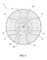
- Fig. 5 is a front view of the light device 1.
- the first base plate 4 mounts the first light sources 8 of eight pieces in total at equal intervals in a ring shape in a copper foil section 12 arranged on the bottom section of the bottomed cylindrical shape thereof.
- An extension section 4a corresponding to the side face of the bottomed cylindrical shape stands toward the irradiation direction A side so as to surround the first light sources 8 by bending the end of the first base plate 4.
- the extension section 4a is extended to a position adjacent to the rear surface side of the lens 3, a projection section 9 of a ring shape abutting on the extension section 4a is formed on the rear surface side of the lens 3, and therefore the extension section 4a abuts on the rear surface side of the lens 3.
- irradiation light 8a of the first light sources 8 is prevented from leaking sideways, and reduction of the light quantity of the light emitting section by the first light sources 8 can be prevented.
- the second base plate 5 is also formed into a bottomed cylindrical shape having a diameter equal to that of the first base plate 4, and the second light sources 11 of eight pieces in total are mounted at equal intervals in a ring shape in a copper foil section 13 arranged on the bottom section thereof.
- a second extension section 5a corresponding to the side face of the bottomed cylindrical shape stands toward the opposite side of the irradiation direction A so as to surround the second light sources 11 by bending the end of the second base plate 5.
- irradiation light 11a of the second light sources 11 comes to be reflected to the irradiation direction A side by the reflector 7 without leaking sideways, and generation of the difference between the light quantity of the irradiation light 11a and the irradiation light 8a can be prevented.
- the extension sections 4a, 5a can prevent reflection to the side and can improve directivity to the irradiation direction A.
- the edge on the outside in the radial direction of the reflector 7 may be formed into a shape same to that of the outer peripheral part of the housing 2 as shown in Figs. 1-3 , and may be configured to be stored in the inside of the joint of the housing 2 and the lens 3 as shown in Fig. 4 .
- an offset amount B is arranged between the front ends of an outer edge 7a of the reflector 7 and the second extension section 5a, which means that the front ends of the outer edge 7 a of the reflector 7 and the second extension section 5a are configured to overlap with each other in the irradiation direction A, thereby the dimension in the irradiation direction A of the light device 1 is made small, and the light device 1 is made compact.
- the light device 1 has a feature that the profile R1 clearly appears by lighting both of the first light sources 8 and the second light sources 11, it is also possible to light either one of the first light sources 8 or the second light sources 11. Therefore, an operation of blinkering the ring section by the second light sources 11 while the small circle section by the first light sources 8 emits the light and so on is possible. In this case also, because the small circle section and the ring section are clearly separated from each other in emitting the light, high viewability can be secured.
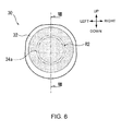
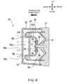
- Fig. 6 is a front view of a light device 30 for a vehicle (hereinafter referred to merely as a light device) in relation with the second embodiment of the present invention. Also, Fig. 7 is a perspective view of the light device 30, and Fig. 8 is a cross-sectional view taken from line VIII-VIII of Fig. 6 .
- the light device 30 applied to a tail light device of a motorcycle is configured to accommodate a base plate 34 that mounts the light sources and a reflector 39 in a space formed between a housing 31 and a lens 33.
- the housing 31 is formed of a black resin and the like
- the lens 33 is formed of a colorless transparent or colored transparent resin.
- a colorless transparent or colored transparent outer lens 32 is arranged outside the lens 33.
- the reflector 39 that engages with the inside of the housing 31 is formed of a resin and the like, and a reflecting surface by plating, metal vapor deposition and the like is arranged thereon.
- first light sources 36 and second light sources 38 are mounted on the front and rear surfaces of the single base plate 34, respectively.
- the base plate 34 formed into a bottomed cylindrical shape is fastened along with the reflector 39 to the housing 31 using a fastening member 37 such as a screw.
- a fastening member 37 such as a screw.
- the first light sources 36 and the second light sources 38 are mounted on the front and rear surfaces of the base plate 34. Therefore, the light axis of the first light sources 36 comes to be oriented to the direction same to the irradiation direction A, and the light axis of the second light sources 38 comes to be oriented to the direction opposite to the irradiation direction A.
- the base plate 34 mounts at least two pieces of the first light sources 36 at equal intervals in a ring shape in a copper foil section 40 arranged on the bottom section of the bottomed cylindrical shape thereof.
- An extension section 34a corresponding to the side face of the bottomed cylindrical shape stands toward the irradiation direction A side so as to surround the first light sources 36 by bending the end of the base plate 34.
- the extension section 34a is extended to a position abutting on the rear surface side of the lens 33.
- irradiation light 36a of the first light sources 36 is prevented from leaking sideways, and reduction of the light quantity of the light emitting section by the first light sources 36 can be prevented.
- the edge of the reflector 39 is extended toward the irradiation direction A side, and extends to a position adjacent to the side of the second light sources 38.
- irradiation light 38a of the second light sources 38 is reflected to the irradiation direction A side by the reflector 39 without leaking sideways.
- the lens 33 is supported by a cylindrical cover 35 that is fixed to the housing 31 side.
- This cylindrical cover 35 is formed of a resin colored in an optional color and so on, and has a function of preventing the base plate 34 and the like from being viewed from the outside in addition to preventing the irradiation light 38a of the second light sources 38 from leaking sideways.
- a recess 33a of a cylindrical shape is formed inside the extension section 34a.
- a wave-like lens cut is arranged on the rear surface side of the recess 33a, and variation in the appearance is further given to the light emitting section inside the extension section 34a.
- the unevenness is not arranged in the outer lens 32 outside the lens 33, and it is configured to obtain only the visual effect by arranging the recess 33a without giving variation in the smooth profile of the light device 30.
- the base plate supporting the LED light sources is disposed perpendicularly to the irradiation direction of the light device and the extension section surrounding the first light sources and standing so as to be oriented to the irradiation section is arranged, the irradiation light of the first light sources is kept inside the profile formed by the extension section and the irradiation light of the second light sources is emitted outside the profile formed by the extension section, and therefore such visual effect can be secured that the inside and outside of the extension section are viewed separately and the profile of the extension section appears so as to be emphasized within the irradiation range of the light device.
- viewability of the light device for a vehicle can be improved by a simple structure without increasing the light quantity itself.
- the shape and structure of the light device for a vehicle are not limited to the embodiments described above, and various alterations are possible.
- the extension section of the base plate can be configured so as to be integral with or separate from the bottom section of the base plate, and can be formed into a polygonal shape or an optional shape in the front view of the light device.
- the light device for a vehicle in relation with the present invention can be applied to various light devices such as a head light, tail light device, position light and the like in addition to the blinker device.
Landscapes
- Engineering & Computer Science (AREA)
- General Engineering & Computer Science (AREA)
- Mechanical Engineering (AREA)
- Physics & Mathematics (AREA)
- Microelectronics & Electronic Packaging (AREA)
- Optics & Photonics (AREA)
- Non-Portable Lighting Devices Or Systems Thereof (AREA)
Applications Claiming Priority (1)
| Application Number | Priority Date | Filing Date | Title |
|---|---|---|---|
| JP2014047875A JP5913405B2 (ja) | 2014-03-11 | 2014-03-11 | 車両用灯火器 |
Publications (2)
| Publication Number | Publication Date |
|---|---|
| EP2918448A1 true EP2918448A1 (fr) | 2015-09-16 |
| EP2918448B1 EP2918448B1 (fr) | 2018-05-30 |
Family
ID=52633125
Family Applications (1)
| Application Number | Title | Priority Date | Filing Date |
|---|---|---|---|
| EP15157938.0A Active EP2918448B1 (fr) | 2014-03-11 | 2015-03-06 | Dispositif d'éclairage pour véhicule |
Country Status (3)
| Country | Link |
|---|---|
| US (1) | US10030834B2 (fr) |
| EP (1) | EP2918448B1 (fr) |
| JP (1) | JP5913405B2 (fr) |
Cited By (3)
| Publication number | Priority date | Publication date | Assignee | Title |
|---|---|---|---|---|
| EP3403880A4 (fr) * | 2016-03-29 | 2018-11-21 | Honda Motor Co., Ltd. | Dispositif d'éclairage |
| WO2020011424A1 (fr) * | 2018-07-11 | 2020-01-16 | Volkswagen Aktiengesellschaft | Indicateur de direction de roulement d'un véhicule automobile |
| FR3126029A1 (fr) * | 2021-08-04 | 2023-02-10 | Valeo Vision | Module lumineux pour véhicule automobile et procédé d’assemblage d’un tel module lumineux |
Families Citing this family (3)
| Publication number | Priority date | Publication date | Assignee | Title |
|---|---|---|---|---|
| FR3025289B1 (fr) * | 2014-09-03 | 2019-07-26 | Zodiac Aero Electric | Projecteur d'eclairage et/ou de signalisation exterieur et systeme d'eclairage et/ou de signalisation correspondant |
| US11225299B2 (en) * | 2019-07-31 | 2022-01-18 | Niterider Technical Lighting & Video Systems, Inc. | Light assembly |
| CN114641650A (zh) * | 2019-12-25 | 2022-06-17 | 株式会社小糸制作所 | 两轮车用前照灯 |
Citations (4)
| Publication number | Priority date | Publication date | Assignee | Title |
|---|---|---|---|---|
| US20040120160A1 (en) * | 2002-07-24 | 2004-06-24 | Koito Manufacturing Co., Ltd. | Vehicular lamp |
| US20060239022A1 (en) * | 2005-04-21 | 2006-10-26 | Koito Manufacturing Co., Ltd. | Projector-type lamp unit for vehicle |
| JP2007035499A (ja) | 2005-07-28 | 2007-02-08 | Honda Motor Co Ltd | 照明装置 |
| FR2896029A1 (fr) * | 2005-12-20 | 2007-07-13 | Valeo Vision Sa | Module d'eclairage comportant des diodes electroluminescentes. |
Family Cites Families (8)
| Publication number | Priority date | Publication date | Assignee | Title |
|---|---|---|---|---|
| US5561346A (en) * | 1994-08-10 | 1996-10-01 | Byrne; David J. | LED lamp construction |
| DE10019557A1 (de) * | 2000-04-20 | 2001-10-25 | Hella Kg Hueck & Co | Fahrzeugleuchte |
| US6682211B2 (en) * | 2001-09-28 | 2004-01-27 | Osram Sylvania Inc. | Replaceable LED lamp capsule |
| JP2003258317A (ja) * | 2002-02-28 | 2003-09-12 | Toyoda Gosei Co Ltd | 発光ダイオード及び灯具 |
| JP4027688B2 (ja) * | 2002-03-15 | 2007-12-26 | 株式会社小糸製作所 | 車両用灯具 |
| DE10249113B4 (de) * | 2002-10-22 | 2010-04-08 | Odelo Gmbh | Fahrzeugleuchte, insbesondere Heckleuchte, vorzugsweise für Kraftfahrzeuge |
| US7431486B2 (en) * | 2006-08-22 | 2008-10-07 | Philips Lumileds Lighting Company, Llc | LED assembly for rear lamps in an automobile |
| KR101262546B1 (ko) * | 2011-11-09 | 2013-05-08 | 기아자동차주식회사 | 차량용 램프구조 |
-
2014
- 2014-03-11 JP JP2014047875A patent/JP5913405B2/ja active Active
-
2015
- 2015-03-04 US US14/638,376 patent/US10030834B2/en active Active
- 2015-03-06 EP EP15157938.0A patent/EP2918448B1/fr active Active
Patent Citations (4)
| Publication number | Priority date | Publication date | Assignee | Title |
|---|---|---|---|---|
| US20040120160A1 (en) * | 2002-07-24 | 2004-06-24 | Koito Manufacturing Co., Ltd. | Vehicular lamp |
| US20060239022A1 (en) * | 2005-04-21 | 2006-10-26 | Koito Manufacturing Co., Ltd. | Projector-type lamp unit for vehicle |
| JP2007035499A (ja) | 2005-07-28 | 2007-02-08 | Honda Motor Co Ltd | 照明装置 |
| FR2896029A1 (fr) * | 2005-12-20 | 2007-07-13 | Valeo Vision Sa | Module d'eclairage comportant des diodes electroluminescentes. |
Cited By (3)
| Publication number | Priority date | Publication date | Assignee | Title |
|---|---|---|---|---|
| EP3403880A4 (fr) * | 2016-03-29 | 2018-11-21 | Honda Motor Co., Ltd. | Dispositif d'éclairage |
| WO2020011424A1 (fr) * | 2018-07-11 | 2020-01-16 | Volkswagen Aktiengesellschaft | Indicateur de direction de roulement d'un véhicule automobile |
| FR3126029A1 (fr) * | 2021-08-04 | 2023-02-10 | Valeo Vision | Module lumineux pour véhicule automobile et procédé d’assemblage d’un tel module lumineux |
Also Published As
| Publication number | Publication date |
|---|---|
| US10030834B2 (en) | 2018-07-24 |
| JP2015173024A (ja) | 2015-10-01 |
| US20150260365A1 (en) | 2015-09-17 |
| EP2918448B1 (fr) | 2018-05-30 |
| JP5913405B2 (ja) | 2016-04-27 |
Similar Documents
| Publication | Publication Date | Title |
|---|---|---|
| US10030834B2 (en) | Light device for vehicle | |
| JP6029298B2 (ja) | 車両用灯具 | |
| JP6415165B2 (ja) | 車両用灯具 | |
| JP5842117B2 (ja) | 照明装置 | |
| JP6413717B2 (ja) | 車両用灯具 | |
| JPWO2014038116A1 (ja) | 照明装置 | |
| JP6432835B2 (ja) | 照明装置、および照明装置の設置構造 | |
| EP3168528B1 (fr) | Dispositif d'éclairage de véhicule | |
| US10816157B2 (en) | Vehicular illumination device | |
| JP6218781B2 (ja) | 光源ユニット及び照明装置 | |
| US20130114281A1 (en) | Vehicle lamp structure | |
| KR101865943B1 (ko) | 차량용 등화장치 | |
| JP2016184548A (ja) | 車両用灯具 | |
| JP2017076495A (ja) | 光源ユニット及び照明装置 | |
| JP2014143128A (ja) | 両面発光ledランプ | |
| JP2020004546A (ja) | 照明器具用フードおよび照明器具 | |
| JP2005293994A (ja) | 照明灯具 | |
| JP2017062914A (ja) | 車両用灯具 | |
| JP6054093B2 (ja) | 車両用灯具 | |
| EP2696133A2 (fr) | Lampe d'éclairage de véhicule | |
| JP2020024789A (ja) | 車両用照明装置 | |
| JP2017220465A (ja) | 照明装置の枠体及び照明装置 | |
| US20140140070A1 (en) | Led lamp | |
| JP2011034899A (ja) | 車両用灯具 | |
| JP2017152408A (ja) | 照明装置 |
Legal Events
| Date | Code | Title | Description |
|---|---|---|---|
| PUAI | Public reference made under article 153(3) epc to a published international application that has entered the european phase |
Free format text: ORIGINAL CODE: 0009012 |
|
| AK | Designated contracting states |
Kind code of ref document: A1 Designated state(s): AL AT BE BG CH CY CZ DE DK EE ES FI FR GB GR HR HU IE IS IT LI LT LU LV MC MK MT NL NO PL PT RO RS SE SI SK SM TR |
|
| AX | Request for extension of the european patent |
Extension state: BA ME |
|
| 17P | Request for examination filed |
Effective date: 20160311 |
|
| RBV | Designated contracting states (corrected) |
Designated state(s): AL AT BE BG CH CY CZ DE DK EE ES FI FR GB GR HR HU IE IS IT LI LT LU LV MC MK MT NL NO PL PT RO RS SE SI SK SM TR |
|
| GRAP | Despatch of communication of intention to grant a patent |
Free format text: ORIGINAL CODE: EPIDOSNIGR1 |
|
| STAA | Information on the status of an ep patent application or granted ep patent |
Free format text: STATUS: GRANT OF PATENT IS INTENDED |
|
| INTG | Intention to grant announced |
Effective date: 20171218 |
|
| GRAS | Grant fee paid |
Free format text: ORIGINAL CODE: EPIDOSNIGR3 |
|
| GRAA | (expected) grant |
Free format text: ORIGINAL CODE: 0009210 |
|
| STAA | Information on the status of an ep patent application or granted ep patent |
Free format text: STATUS: THE PATENT HAS BEEN GRANTED |
|
| AK | Designated contracting states |
Kind code of ref document: B1 Designated state(s): AL AT BE BG CH CY CZ DE DK EE ES FI FR GB GR HR HU IE IS IT LI LT LU LV MC MK MT NL NO PL PT RO RS SE SI SK SM TR |
|
| REG | Reference to a national code |
Ref country code: GB Ref legal event code: FG4D |
|
| REG | Reference to a national code |
Ref country code: CH Ref legal event code: EP |
|
| REG | Reference to a national code |
Ref country code: AT Ref legal event code: REF Ref document number: 1003271 Country of ref document: AT Kind code of ref document: T Effective date: 20180615 |
|
| REG | Reference to a national code |
Ref country code: IE Ref legal event code: FG4D |
|
| REG | Reference to a national code |
Ref country code: DE Ref legal event code: R096 Ref document number: 602015011548 Country of ref document: DE |
|
| REG | Reference to a national code |
Ref country code: NL Ref legal event code: MP Effective date: 20180530 |
|
| REG | Reference to a national code |
Ref country code: LT Ref legal event code: MG4D |
|
| PG25 | Lapsed in a contracting state [announced via postgrant information from national office to epo] |
Ref country code: NO Free format text: LAPSE BECAUSE OF FAILURE TO SUBMIT A TRANSLATION OF THE DESCRIPTION OR TO PAY THE FEE WITHIN THE PRESCRIBED TIME-LIMIT Effective date: 20180830 Ref country code: CY Free format text: LAPSE BECAUSE OF FAILURE TO SUBMIT A TRANSLATION OF THE DESCRIPTION OR TO PAY THE FEE WITHIN THE PRESCRIBED TIME-LIMIT Effective date: 20180530 Ref country code: SE Free format text: LAPSE BECAUSE OF FAILURE TO SUBMIT A TRANSLATION OF THE DESCRIPTION OR TO PAY THE FEE WITHIN THE PRESCRIBED TIME-LIMIT Effective date: 20180530 Ref country code: BG Free format text: LAPSE BECAUSE OF FAILURE TO SUBMIT A TRANSLATION OF THE DESCRIPTION OR TO PAY THE FEE WITHIN THE PRESCRIBED TIME-LIMIT Effective date: 20180830 Ref country code: FI Free format text: LAPSE BECAUSE OF FAILURE TO SUBMIT A TRANSLATION OF THE DESCRIPTION OR TO PAY THE FEE WITHIN THE PRESCRIBED TIME-LIMIT Effective date: 20180530 Ref country code: ES Free format text: LAPSE BECAUSE OF FAILURE TO SUBMIT A TRANSLATION OF THE DESCRIPTION OR TO PAY THE FEE WITHIN THE PRESCRIBED TIME-LIMIT Effective date: 20180530 Ref country code: LT Free format text: LAPSE BECAUSE OF FAILURE TO SUBMIT A TRANSLATION OF THE DESCRIPTION OR TO PAY THE FEE WITHIN THE PRESCRIBED TIME-LIMIT Effective date: 20180530 |
|
| PG25 | Lapsed in a contracting state [announced via postgrant information from national office to epo] |
Ref country code: LV Free format text: LAPSE BECAUSE OF FAILURE TO SUBMIT A TRANSLATION OF THE DESCRIPTION OR TO PAY THE FEE WITHIN THE PRESCRIBED TIME-LIMIT Effective date: 20180530 Ref country code: HR Free format text: LAPSE BECAUSE OF FAILURE TO SUBMIT A TRANSLATION OF THE DESCRIPTION OR TO PAY THE FEE WITHIN THE PRESCRIBED TIME-LIMIT Effective date: 20180530 Ref country code: GR Free format text: LAPSE BECAUSE OF FAILURE TO SUBMIT A TRANSLATION OF THE DESCRIPTION OR TO PAY THE FEE WITHIN THE PRESCRIBED TIME-LIMIT Effective date: 20180831 Ref country code: RS Free format text: LAPSE BECAUSE OF FAILURE TO SUBMIT A TRANSLATION OF THE DESCRIPTION OR TO PAY THE FEE WITHIN THE PRESCRIBED TIME-LIMIT Effective date: 20180530 |
|
| REG | Reference to a national code |
Ref country code: AT Ref legal event code: MK05 Ref document number: 1003271 Country of ref document: AT Kind code of ref document: T Effective date: 20180530 |
|
| PG25 | Lapsed in a contracting state [announced via postgrant information from national office to epo] |
Ref country code: NL Free format text: LAPSE BECAUSE OF FAILURE TO SUBMIT A TRANSLATION OF THE DESCRIPTION OR TO PAY THE FEE WITHIN THE PRESCRIBED TIME-LIMIT Effective date: 20180530 |
|
| PG25 | Lapsed in a contracting state [announced via postgrant information from national office to epo] |
Ref country code: EE Free format text: LAPSE BECAUSE OF FAILURE TO SUBMIT A TRANSLATION OF THE DESCRIPTION OR TO PAY THE FEE WITHIN THE PRESCRIBED TIME-LIMIT Effective date: 20180530 Ref country code: AT Free format text: LAPSE BECAUSE OF FAILURE TO SUBMIT A TRANSLATION OF THE DESCRIPTION OR TO PAY THE FEE WITHIN THE PRESCRIBED TIME-LIMIT Effective date: 20180530 Ref country code: PL Free format text: LAPSE BECAUSE OF FAILURE TO SUBMIT A TRANSLATION OF THE DESCRIPTION OR TO PAY THE FEE WITHIN THE PRESCRIBED TIME-LIMIT Effective date: 20180530 Ref country code: DK Free format text: LAPSE BECAUSE OF FAILURE TO SUBMIT A TRANSLATION OF THE DESCRIPTION OR TO PAY THE FEE WITHIN THE PRESCRIBED TIME-LIMIT Effective date: 20180530 Ref country code: RO Free format text: LAPSE BECAUSE OF FAILURE TO SUBMIT A TRANSLATION OF THE DESCRIPTION OR TO PAY THE FEE WITHIN THE PRESCRIBED TIME-LIMIT Effective date: 20180530 Ref country code: CZ Free format text: LAPSE BECAUSE OF FAILURE TO SUBMIT A TRANSLATION OF THE DESCRIPTION OR TO PAY THE FEE WITHIN THE PRESCRIBED TIME-LIMIT Effective date: 20180530 Ref country code: SK Free format text: LAPSE BECAUSE OF FAILURE TO SUBMIT A TRANSLATION OF THE DESCRIPTION OR TO PAY THE FEE WITHIN THE PRESCRIBED TIME-LIMIT Effective date: 20180530 |
|
| REG | Reference to a national code |
Ref country code: CH Ref legal event code: PK Free format text: BERICHTIGUNGEN |
|
| RIC2 | Information provided on ipc code assigned after grant |
Ipc: F21S 8/10 20060101ALI20150708BHEP Ipc: B62J 6/04 20060101ALI20150708BHEP Ipc: B62J 6/00 20060101ALI20150708BHEP Ipc: B60Q 1/38 20060101AFI20150708BHEP |
|
| PG25 | Lapsed in a contracting state [announced via postgrant information from national office to epo] |
Ref country code: SM Free format text: LAPSE BECAUSE OF FAILURE TO SUBMIT A TRANSLATION OF THE DESCRIPTION OR TO PAY THE FEE WITHIN THE PRESCRIBED TIME-LIMIT Effective date: 20180530 |
|
| REG | Reference to a national code |
Ref country code: DE Ref legal event code: R097 Ref document number: 602015011548 Country of ref document: DE |
|
| PLBE | No opposition filed within time limit |
Free format text: ORIGINAL CODE: 0009261 |
|
| STAA | Information on the status of an ep patent application or granted ep patent |
Free format text: STATUS: NO OPPOSITION FILED WITHIN TIME LIMIT |
|
| PGFP | Annual fee paid to national office [announced via postgrant information from national office to epo] |
Ref country code: FR Payment date: 20181218 Year of fee payment: 16 |
|
| 26N | No opposition filed |
Effective date: 20190301 |
|
| PG25 | Lapsed in a contracting state [announced via postgrant information from national office to epo] |
Ref country code: SI Free format text: LAPSE BECAUSE OF FAILURE TO SUBMIT A TRANSLATION OF THE DESCRIPTION OR TO PAY THE FEE WITHIN THE PRESCRIBED TIME-LIMIT Effective date: 20180530 |
|
| PG25 | Lapsed in a contracting state [announced via postgrant information from national office to epo] |
Ref country code: MC Free format text: LAPSE BECAUSE OF FAILURE TO SUBMIT A TRANSLATION OF THE DESCRIPTION OR TO PAY THE FEE WITHIN THE PRESCRIBED TIME-LIMIT Effective date: 20180530 |
|
| REG | Reference to a national code |
Ref country code: CH Ref legal event code: PL |
|
| PG25 | Lapsed in a contracting state [announced via postgrant information from national office to epo] |
Ref country code: AL Free format text: LAPSE BECAUSE OF FAILURE TO SUBMIT A TRANSLATION OF THE DESCRIPTION OR TO PAY THE FEE WITHIN THE PRESCRIBED TIME-LIMIT Effective date: 20180530 Ref country code: LU Free format text: LAPSE BECAUSE OF NON-PAYMENT OF DUE FEES Effective date: 20190306 |
|
| REG | Reference to a national code |
Ref country code: BE Ref legal event code: MM Effective date: 20190331 |
|
| REG | Reference to a national code |
Ref country code: DE Ref legal event code: R084 Ref document number: 602015011548 Country of ref document: DE |
|
| PG25 | Lapsed in a contracting state [announced via postgrant information from national office to epo] |
Ref country code: CH Free format text: LAPSE BECAUSE OF NON-PAYMENT OF DUE FEES Effective date: 20190331 Ref country code: LI Free format text: LAPSE BECAUSE OF NON-PAYMENT OF DUE FEES Effective date: 20190331 Ref country code: IE Free format text: LAPSE BECAUSE OF NON-PAYMENT OF DUE FEES Effective date: 20190306 |
|
| PG25 | Lapsed in a contracting state [announced via postgrant information from national office to epo] |
Ref country code: FR Free format text: LAPSE BECAUSE OF NON-PAYMENT OF DUE FEES Effective date: 20190331 Ref country code: BE Free format text: LAPSE BECAUSE OF NON-PAYMENT OF DUE FEES Effective date: 20190331 |
|
| PG25 | Lapsed in a contracting state [announced via postgrant information from national office to epo] |
Ref country code: TR Free format text: LAPSE BECAUSE OF FAILURE TO SUBMIT A TRANSLATION OF THE DESCRIPTION OR TO PAY THE FEE WITHIN THE PRESCRIBED TIME-LIMIT Effective date: 20180530 |
|
| PG25 | Lapsed in a contracting state [announced via postgrant information from national office to epo] |
Ref country code: PT Free format text: LAPSE BECAUSE OF FAILURE TO SUBMIT A TRANSLATION OF THE DESCRIPTION OR TO PAY THE FEE WITHIN THE PRESCRIBED TIME-LIMIT Effective date: 20181001 Ref country code: MT Free format text: LAPSE BECAUSE OF NON-PAYMENT OF DUE FEES Effective date: 20190306 |
|
| GBPC | Gb: european patent ceased through non-payment of renewal fee |
Effective date: 20200306 |
|
| PG25 | Lapsed in a contracting state [announced via postgrant information from national office to epo] |
Ref country code: GB Free format text: LAPSE BECAUSE OF NON-PAYMENT OF DUE FEES Effective date: 20200306 |
|
| PG25 | Lapsed in a contracting state [announced via postgrant information from national office to epo] |
Ref country code: IS Free format text: LAPSE BECAUSE OF FAILURE TO SUBMIT A TRANSLATION OF THE DESCRIPTION OR TO PAY THE FEE WITHIN THE PRESCRIBED TIME-LIMIT Effective date: 20180930 |
|
| PG25 | Lapsed in a contracting state [announced via postgrant information from national office to epo] |
Ref country code: HU Free format text: LAPSE BECAUSE OF FAILURE TO SUBMIT A TRANSLATION OF THE DESCRIPTION OR TO PAY THE FEE WITHIN THE PRESCRIBED TIME-LIMIT; INVALID AB INITIO Effective date: 20150306 |
|
| PG25 | Lapsed in a contracting state [announced via postgrant information from national office to epo] |
Ref country code: MK Free format text: LAPSE BECAUSE OF FAILURE TO SUBMIT A TRANSLATION OF THE DESCRIPTION OR TO PAY THE FEE WITHIN THE PRESCRIBED TIME-LIMIT Effective date: 20180530 |
|
| PGFP | Annual fee paid to national office [announced via postgrant information from national office to epo] |
Ref country code: DE Payment date: 20240220 Year of fee payment: 10 |
|
| PGFP | Annual fee paid to national office [announced via postgrant information from national office to epo] |
Ref country code: IT Payment date: 20240220 Year of fee payment: 10 |