EP2918251A1 - Endoprothèse endoluminale autoexpansible tressée - Google Patents
Endoprothèse endoluminale autoexpansible tressée Download PDFInfo
- Publication number
- EP2918251A1 EP2918251A1 EP13854131.3A EP13854131A EP2918251A1 EP 2918251 A1 EP2918251 A1 EP 2918251A1 EP 13854131 A EP13854131 A EP 13854131A EP 2918251 A1 EP2918251 A1 EP 2918251A1
- Authority
- EP
- European Patent Office
- Prior art keywords
- group
- grids
- wave band
- wave
- cross
- Prior art date
- Legal status (The legal status is an assumption and is not a legal conclusion. Google has not performed a legal analysis and makes no representation as to the accuracy of the status listed.)
- Granted
Links
- 238000004519 manufacturing process Methods 0.000 title claims description 24
- 238000004132 cross linking Methods 0.000 claims abstract description 89
- 238000009954 braiding Methods 0.000 claims description 45
- 238000000034 method Methods 0.000 claims description 29
- 229910001000 nickel titanium Inorganic materials 0.000 description 87
- HZEWFHLRYVTOIW-UHFFFAOYSA-N [Ti].[Ni] Chemical compound [Ti].[Ni] HZEWFHLRYVTOIW-UHFFFAOYSA-N 0.000 description 82
- 238000004804 winding Methods 0.000 description 29
- 238000010586 diagram Methods 0.000 description 25
- 238000004904 shortening Methods 0.000 description 16
- 230000006872 improvement Effects 0.000 description 14
- 208000027418 Wounds and injury Diseases 0.000 description 13
- 206010060965 Arterial stenosis Diseases 0.000 description 11
- 210000001367 artery Anatomy 0.000 description 10
- 238000002399 angioplasty Methods 0.000 description 9
- 210000003414 extremity Anatomy 0.000 description 7
- 208000031104 Arterial Occlusive disease Diseases 0.000 description 5
- 208000021328 arterial occlusion Diseases 0.000 description 5
- 230000000694 effects Effects 0.000 description 5
- 208000002193 Pain Diseases 0.000 description 4
- 238000005452 bending Methods 0.000 description 4
- 230000008859 change Effects 0.000 description 4
- 208000037265 diseases, disorders, signs and symptoms Diseases 0.000 description 4
- 238000006073 displacement reaction Methods 0.000 description 4
- 208000007536 Thrombosis Diseases 0.000 description 3
- 238000007887 coronary angioplasty Methods 0.000 description 3
- 230000006378 damage Effects 0.000 description 3
- 201000010099 disease Diseases 0.000 description 3
- 210000003141 lower extremity Anatomy 0.000 description 3
- 230000008569 process Effects 0.000 description 3
- 238000011084 recovery Methods 0.000 description 3
- 208000037803 restenosis Diseases 0.000 description 3
- 201000001320 Atherosclerosis Diseases 0.000 description 2
- 208000037260 Atherosclerotic Plaque Diseases 0.000 description 2
- 201000004569 Blindness Diseases 0.000 description 2
- 208000005189 Embolism Diseases 0.000 description 2
- 206010003230 arteritis Diseases 0.000 description 2
- 230000009286 beneficial effect Effects 0.000 description 2
- 238000002513 implantation Methods 0.000 description 2
- 208000014674 injury Diseases 0.000 description 2
- 238000010147 laser engraving Methods 0.000 description 2
- 238000011542 limb amputation Methods 0.000 description 2
- 231100000862 numbness Toxicity 0.000 description 2
- 230000000717 retained effect Effects 0.000 description 2
- 230000002966 stenotic effect Effects 0.000 description 2
- 238000001356 surgical procedure Methods 0.000 description 2
- 208000024891 symptom Diseases 0.000 description 2
- 210000005166 vasculature Anatomy 0.000 description 2
- 200000000007 Arterial disease Diseases 0.000 description 1
- 206010007687 Carotid artery stenosis Diseases 0.000 description 1
- 206010019233 Headaches Diseases 0.000 description 1
- 239000004677 Nylon Substances 0.000 description 1
- 206010033546 Pallor Diseases 0.000 description 1
- 208000031481 Pathologic Constriction Diseases 0.000 description 1
- 208000003443 Unconsciousness Diseases 0.000 description 1
- 230000001154 acute effect Effects 0.000 description 1
- 206010001902 amaurosis Diseases 0.000 description 1
- 239000003146 anticoagulant agent Substances 0.000 description 1
- 230000005988 arterial dysfunction Effects 0.000 description 1
- 210000000013 bile duct Anatomy 0.000 description 1
- 239000008280 blood Substances 0.000 description 1
- 210000004369 blood Anatomy 0.000 description 1
- 230000036772 blood pressure Effects 0.000 description 1
- 210000000621 bronchi Anatomy 0.000 description 1
- 210000001715 carotid artery Anatomy 0.000 description 1
- 208000006170 carotid stenosis Diseases 0.000 description 1
- 230000001684 chronic effect Effects 0.000 description 1
- 230000001427 coherent effect Effects 0.000 description 1
- 230000000916 dilatatory effect Effects 0.000 description 1
- 238000009826 distribution Methods 0.000 description 1
- 208000002173 dizziness Diseases 0.000 description 1
- 229940079593 drug Drugs 0.000 description 1
- 239000003814 drug Substances 0.000 description 1
- 238000002651 drug therapy Methods 0.000 description 1
- 208000008487 fibromuscular dysplasia Diseases 0.000 description 1
- 231100000869 headache Toxicity 0.000 description 1
- 239000007943 implant Substances 0.000 description 1
- 230000000302 ischemic effect Effects 0.000 description 1
- 230000003902 lesion Effects 0.000 description 1
- 150000002632 lipids Chemical class 0.000 description 1
- 230000007774 longterm Effects 0.000 description 1
- 239000000463 material Substances 0.000 description 1
- 239000011159 matrix material Substances 0.000 description 1
- 238000012986 modification Methods 0.000 description 1
- 230000004048 modification Effects 0.000 description 1
- 229920001778 nylon Polymers 0.000 description 1
- 239000004033 plastic Substances 0.000 description 1
- 230000002980 postoperative effect Effects 0.000 description 1
- 230000001105 regulatory effect Effects 0.000 description 1
- 210000002254 renal artery Anatomy 0.000 description 1
- 238000007493 shaping process Methods 0.000 description 1
- 229910001220 stainless steel Inorganic materials 0.000 description 1
- 230000036262 stenosis Effects 0.000 description 1
- 208000037804 stenosis Diseases 0.000 description 1
- 210000003270 subclavian artery Anatomy 0.000 description 1
- 206010042772 syncope Diseases 0.000 description 1
- 208000011580 syndromic disease Diseases 0.000 description 1
- 230000001225 therapeutic effect Effects 0.000 description 1
- 238000002560 therapeutic procedure Methods 0.000 description 1
- 238000013151 thrombectomy Methods 0.000 description 1
- 230000002537 thrombolytic effect Effects 0.000 description 1
- 230000007704 transition Effects 0.000 description 1
- 210000003708 urethra Anatomy 0.000 description 1
- 230000002792 vascular Effects 0.000 description 1
- 210000003462 vein Anatomy 0.000 description 1
Images


Classifications
-
- A—HUMAN NECESSITIES
- A61—MEDICAL OR VETERINARY SCIENCE; HYGIENE
- A61F—FILTERS IMPLANTABLE INTO BLOOD VESSELS; PROSTHESES; DEVICES PROVIDING PATENCY TO, OR PREVENTING COLLAPSING OF, TUBULAR STRUCTURES OF THE BODY, e.g. STENTS; ORTHOPAEDIC, NURSING OR CONTRACEPTIVE DEVICES; FOMENTATION; TREATMENT OR PROTECTION OF EYES OR EARS; BANDAGES, DRESSINGS OR ABSORBENT PADS; FIRST-AID KITS
- A61F2/00—Filters implantable into blood vessels; Prostheses, i.e. artificial substitutes or replacements for parts of the body; Appliances for connecting them with the body; Devices providing patency to, or preventing collapsing of, tubular structures of the body, e.g. stents
- A61F2/82—Devices providing patency to, or preventing collapsing of, tubular structures of the body, e.g. stents
- A61F2/86—Stents in a form characterised by the wire-like elements; Stents in the form characterised by a net-like or mesh-like structure
- A61F2/89—Stents in a form characterised by the wire-like elements; Stents in the form characterised by a net-like or mesh-like structure the wire-like elements comprising two or more adjacent rings flexibly connected by separate members
-
- A—HUMAN NECESSITIES
- A61—MEDICAL OR VETERINARY SCIENCE; HYGIENE
- A61F—FILTERS IMPLANTABLE INTO BLOOD VESSELS; PROSTHESES; DEVICES PROVIDING PATENCY TO, OR PREVENTING COLLAPSING OF, TUBULAR STRUCTURES OF THE BODY, e.g. STENTS; ORTHOPAEDIC, NURSING OR CONTRACEPTIVE DEVICES; FOMENTATION; TREATMENT OR PROTECTION OF EYES OR EARS; BANDAGES, DRESSINGS OR ABSORBENT PADS; FIRST-AID KITS
- A61F2/00—Filters implantable into blood vessels; Prostheses, i.e. artificial substitutes or replacements for parts of the body; Appliances for connecting them with the body; Devices providing patency to, or preventing collapsing of, tubular structures of the body, e.g. stents
- A61F2/82—Devices providing patency to, or preventing collapsing of, tubular structures of the body, e.g. stents
- A61F2/86—Stents in a form characterised by the wire-like elements; Stents in the form characterised by a net-like or mesh-like structure
- A61F2/90—Stents in a form characterised by the wire-like elements; Stents in the form characterised by a net-like or mesh-like structure characterised by a net-like or mesh-like structure
-
- D—TEXTILES; PAPER
- D04—BRAIDING; LACE-MAKING; KNITTING; TRIMMINGS; NON-WOVEN FABRICS
- D04C—BRAIDING OR MANUFACTURE OF LACE, INCLUDING BOBBIN-NET OR CARBONISED LACE; BRAIDING MACHINES; BRAID; LACE
- D04C1/00—Braid or lace, e.g. pillow-lace; Processes for the manufacture thereof
- D04C1/06—Braid or lace serving particular purposes
-
- D—TEXTILES; PAPER
- D04—BRAIDING; LACE-MAKING; KNITTING; TRIMMINGS; NON-WOVEN FABRICS
- D04C—BRAIDING OR MANUFACTURE OF LACE, INCLUDING BOBBIN-NET OR CARBONISED LACE; BRAIDING MACHINES; BRAID; LACE
- D04C3/00—Braiding or lacing machines
- D04C3/48—Auxiliary devices
-
- A—HUMAN NECESSITIES
- A61—MEDICAL OR VETERINARY SCIENCE; HYGIENE
- A61F—FILTERS IMPLANTABLE INTO BLOOD VESSELS; PROSTHESES; DEVICES PROVIDING PATENCY TO, OR PREVENTING COLLAPSING OF, TUBULAR STRUCTURES OF THE BODY, e.g. STENTS; ORTHOPAEDIC, NURSING OR CONTRACEPTIVE DEVICES; FOMENTATION; TREATMENT OR PROTECTION OF EYES OR EARS; BANDAGES, DRESSINGS OR ABSORBENT PADS; FIRST-AID KITS
- A61F2230/00—Geometry of prostheses classified in groups A61F2/00 - A61F2/26 or A61F2/82 or A61F9/00 or A61F11/00 or subgroups thereof
- A61F2230/0063—Three-dimensional shapes
- A61F2230/0069—Three-dimensional shapes cylindrical
-
- A—HUMAN NECESSITIES
- A61—MEDICAL OR VETERINARY SCIENCE; HYGIENE
- A61F—FILTERS IMPLANTABLE INTO BLOOD VESSELS; PROSTHESES; DEVICES PROVIDING PATENCY TO, OR PREVENTING COLLAPSING OF, TUBULAR STRUCTURES OF THE BODY, e.g. STENTS; ORTHOPAEDIC, NURSING OR CONTRACEPTIVE DEVICES; FOMENTATION; TREATMENT OR PROTECTION OF EYES OR EARS; BANDAGES, DRESSINGS OR ABSORBENT PADS; FIRST-AID KITS
- A61F2240/00—Manufacturing or designing of prostheses classified in groups A61F2/00 - A61F2/26 or A61F2/82 or A61F9/00 or A61F11/00 or subgroups thereof
- A61F2240/001—Designing or manufacturing processes
-
- A—HUMAN NECESSITIES
- A61—MEDICAL OR VETERINARY SCIENCE; HYGIENE
- A61F—FILTERS IMPLANTABLE INTO BLOOD VESSELS; PROSTHESES; DEVICES PROVIDING PATENCY TO, OR PREVENTING COLLAPSING OF, TUBULAR STRUCTURES OF THE BODY, e.g. STENTS; ORTHOPAEDIC, NURSING OR CONTRACEPTIVE DEVICES; FOMENTATION; TREATMENT OR PROTECTION OF EYES OR EARS; BANDAGES, DRESSINGS OR ABSORBENT PADS; FIRST-AID KITS
- A61F2250/00—Special features of prostheses classified in groups A61F2/00 - A61F2/26 or A61F2/82 or A61F9/00 or A61F11/00 or subgroups thereof
- A61F2250/0004—Special features of prostheses classified in groups A61F2/00 - A61F2/26 or A61F2/82 or A61F9/00 or A61F11/00 or subgroups thereof adjustable
- A61F2250/001—Special features of prostheses classified in groups A61F2/00 - A61F2/26 or A61F2/82 or A61F9/00 or A61F11/00 or subgroups thereof adjustable for adjusting a diameter
-
- D—TEXTILES; PAPER
- D10—INDEXING SCHEME ASSOCIATED WITH SUBLASSES OF SECTION D, RELATING TO TEXTILES
- D10B—INDEXING SCHEME ASSOCIATED WITH SUBLASSES OF SECTION D, RELATING TO TEXTILES
- D10B2509/00—Medical; Hygiene
- D10B2509/06—Vascular grafts; stents
Definitions
- the present invention relates to a medical instrument for supporting or repairing human vessels, in particular to a braided self-expanding endoluminal stent for endoluminal interventional treatment of arterial stenosis or occlusion and a manufacturing method thereof.
- Human vessels includes arteries, veins, tracheae, bronchi, esophagi, bile ducts, urethras, etc, the diameters of which vary from several millimeters to a few tenths of millimeters.
- Those human vessels may have various diseases, for example, collapse, occlusion and damage, and corresponding endoluminal stents may be used for treating those endoluminal diseases.
- Those endoluminal stents should satisfy some common requirements. For example, they may be encapsulated into tiny sheathes, delivered into human vessels and then released, expanded and then supported at the predetermined endoluminal positions, for the purpose of treatment.
- arteries are more likely to have diseases than other human vessels, endoluminal stents are most commonly used for treating arterial diseases.
- arteries typically circumferential arteries, mainly including carotid artery, subclavian artery, lower extremity artery, renal artery, etc.
- Arterial stenosis or occlusion is mainly caused by atherosclerosis, arteritis, fibromuscular dysplasia, etc.
- Arterial stenosis or occlusion is mainly caused by atherosclerosis, arteritis, fibromuscular dysplasia, etc.
- Arteritis is the common cause of arterial stenosis.
- Carotid artery stenosis may result in ischemic syndromes in the head and eyes, for example, dizziness, headache, syncope, temporary amaurosis, blindness, etc. Sudden onset of subclavian arterial occlusion is usually followed by sudden limb pain, skin temperature drop, skin color change and even limb amputation if severe; and, subclavian arterial stenosis is usually followed by weakness, numbness, cold of limb, and intermittent limb pain after activities. Renal arterial stenosis is likely to result in renal arterial dysfunction.
- medical drug therapy may be adopted which, however, does not work for patients with severe symptoms.
- the physician will make a therapeutic scheme according to the situation of a patient, including drugs for regulating lipid and dropping blood pressure. Some patients may further need to use anticoagulant drugs to reduce the danger of causing thrombus in stenotic arteries by the blood.
- surgical treatment may be adopted.
- the surgical treatment is bypass operation, i.e., arterial bypass grafting. That is, the diseased stenotic arterial segment is bypassed and normal vessels at its two ends are connected by a new path.
- bypass operation i.e., arterial bypass grafting. That is, the diseased stenotic arterial segment is bypassed and normal vessels at its two ends are connected by a new path.
- surgical operation causes big injuries and has many complications.
- Arterial thrombolysis and thrombectomy are applicable to acute iliofemoral artery thrombus or embolism patients, however, are not applicable to chronic vessel stenosis or occlusion lesions.
- transluminal coronary angioplasty Dotter and Judkins first conducted percutaneous angioplasty by a coaxial nylon balloon dilating catheter in 1964, which was the beginning of balloon percutaneous transluminal angioplasty (PTA). With the development of transluminal angioplasty, minimally-invasive therapy is being increasingly applied. Different from the traditional operations, transluminal coronary angioplasty has become a main treatment method for arterial stenosis or occlusion as it causes minimal injury and offers quick postoperative recovery.
- transluminal coronary angioplasties there are mainly two types of transluminal coronary angioplasties, one of which is balloon percutaneous transluminal angioplasty (PTA), and the other is stent implantation.
- PTA balloon percutaneous transluminal angioplasty
- Balloon percutaneous transluminal angioplasty is to expand the diseased vessel by a balloon in order to dredge the vessel.
- balloon percutaneous transluminal angioplasty has a high incidence of complications mainly including plaque or detachment of thrombus which causes embolism of distal vessels.
- Stent implantation is to implant a vascular stent at the diseased vessel position to expand the vessel at the diseased position.
- stents for circumferential vessels there are mainly two kinds of stents for circumferential vessels; i.e., balloon-expandable stents and self-expanding stents.
- balloon-expandable stents it is expanded by a balloon and has a certain radial support force due to plastic deformation.
- Such a stent although accurate in positioning due to small axial shortening after expansion, is poor in its flexibility and thus is just applicable to be placed in a flat vessel; furthermore, the incidence of restenosis is higher than for self-expanding stents.
- self-expanding stent For a self-expanding stent, it can automatically return to its original shape by virtue of its own super-elasticity and shape memory characteristic after being released from the sheath.
- Self-expanding stents have been widely applied due to their excellent performance and fewer complications, and are more applicable to vessels on the limbs (which are often in bending motion) than balloon-expanding stents.
- self-expandable stents for circumferential vessels are almost entirely made of nickel-titanium canals by laser engraving, and only a few of the self-expandable stents are braided from nickel-titanium alloy wires.
- self-expandable endoluminal stents are almost always laser-engraved stents; that is, are stents formed by laser-engraving nickel-titanium alloy tubes and then thermally treating those tubes for shaping.
- Self-expanding endoluminal stents manufactured in this way are not applicable to be bent in human endoluminal positions having activities to some extent, due to their poor flexibility and high occurrence of fatigue fracture.
- the present invention provides a braided self-expandable endoluminal stent to solve the problems of the braided stents in the prior art; for example, difficulties in positioning, small radial support force of the stent, and easy displacement due to shortening, and to avoid the problem that common laser-engraved endoluminal stents are likely to have fatigue fracture at tortuous positions and moveable positions of human vessels.
- a braided self-expandable endoluminal stent including a tubular grid formed by a plurality of axial wave bands connected together along the circumferential direction, the tubular grid having a central axis, a proximal end and a distal end, each of the wave bands comprising a plurality of alternate crests and troughs wound by an elastic filament in the axial direction, the proximal end and the distal end of each of the wave bands being respectively connected to another wave band; on either side of each of the wave bands, there is a wave band abutted thereto side by side; there is at least one cross-linking point between every two wave bands abutted side by side, each of the cross-linking points is formed by intersecting one trough on one of wave bands abutted side by side with one corresponding crest on the other wave band, and at least part of the cross-linking points are fixed cross-linking points; each of
- the tubular grid comprises a plurality of crossing segments connected to each other in the axial direction, each of the crossing segments is tubular and comprises a plurality of crossing points distributed substantially uniformly, and the cross-linking points are only located on a boundary of two adjacent crossing segments, this boundary being a closed loop.
- nk-1 cross-linking points or nk+1 cross-linking points on each of the boundaries wherein, both n and k are natural numbers, n ⁇ 3 and k ⁇ 2.
- the number of crossing points on each of the crossing segments is substantially an integral multiple of that of cross-linking points on each of the boundaries, the difference between the ratio of the two numbers and the nearest integer being less than 0.2.
- the cross-linking points on the boundaries are all fixed cross-linking points.
- the length of each of the crossing segments is equal.
- the length of one of the crossing segments is an integral multiple of that of another crossing segment.
- the diameter of the tubular grid varies in the axial direction.
- the tubular grid comprises at least two segments different in diameter, which are connected to each other in the axial direction, each of the segments of the tubular grid comprises a plurality of wave bands, and there are cross-linking points formed between the wave bands of one of the segments of the tubular grid and the wave bands of another segment of the tubular grid.
- a method for manufacturing a braided self-expanding endoluminal stent comprising a tubular grid having a central axis, a proximal end and a distal end, the manufacturing method comprising the following steps:
- the rest part comprises a third group of grids;
- the elastic filament for the second group of grids is lengthened and then connected to the first group of grids via the third group of grids, and the third group of grids are braided on the first group of grids and the second group of grids in a staggered manner with the lengthened elastic filament; and the first group of grids, the second group of grids and the third group of grids are staggered in turn along the circumferential direction and overlapped to form a plurality of crossing points.
- step 1 cross-linking points are formed between the wave bands of the first group of grids to manufacture the first group of grids into a tubular shape.
- step 1 crossing points are formed between the wave bands of the first group of grids, and a plurality of cross-linking points and a plurality of crossing points are formed between the second group of grids and the first group of grids.
- the present invention further provides a self-expandable endoluminal stent manufactured according to any one of the manufacturing methods described above.
- the braided self-expandable endoluminal stent provided by the present invention uses axial wave bands and inherits the advantages of closed-loop braided endoluminal stents. For example, repeatedly positioning may be realized, that is, the stent may be withdrawn into the sheath after partially released, then to be released again after position adjustment. On the other hand, the shortening is reduced so that the stent is unlikely to experience displacement during the release process; as a result the positioning is accurate and easily controlled. Furthermore, both the flexibility and the axial strength are improved, so that the stent may bear a large bending angle without kinking or losing the radial support force.
- the stent may be implanted into various tortuous diseased parts of the human vasculature.
- the fixed cross-linking points are distributed on the circumference, thereby ensuring the radial support strength of the endoluminal stent; and crossing points are distributed in different crossing segments, thereby facilitating the improvement of the flexibility of the endoluminal stent.
- the crossing points alternate to the fixed cross-linking points, and there are more crossing points than fixed cross-linking points, the density of the grid is enhanced and the stability of the structure is therefore better.
- the coverage to the artery atherosclerotic plaque is increased, the tubular grid is allowed to be deformed appropriately, the stress and the friction force are dispersed evenly, and the shortening, the flexibility and the radial support strength are balanced.
- the present invention provides a braided self-expandable endoluminal stent, including a tubular grid formed by a plurality of axial wave bands connected in the circumferential direction, the tubular grid having a central axis, a proximal end and a distal end, each of the wave bands comprising a plurality of alternant crests and troughs wound by an elastic filament in the axial direction, and the proximal end and the distal end of each of the wave bands being respectively connected to another wave band.
- each of the wave bands On two sides of each of the wave bands, there is a wave band abutted thereto side by side respectively; there is at least one cross-linking point between every two wave bands abutted side by side, each of the cross-linking points is formed by one trough on one of wave bands abutted side by side intersected with one corresponding crest on the other wave band, and at least part of the cross-linking points are fixed cross-linking points (braiding filaments passing through any one fixed cross-linking point are intertwined and fixed with each other at this fixed cross-linking point, not capable of moving with respect to each other), each of the wave bands is further staggered and overlapped with at least another wave band, and a plurality of crossing points are formed by the wave bands which are staggered and overlapped with each other (braiding filaments passing through any one crossing point are crossed at this crossing point, capable of moving with respect to each other); each of the wave bands, together with at least another wave band, forms a group of parallel wave bands
- Circumferentially-oriented sets of pins are provided on the side wall of a cylindrical mandrel, and pins respectively in two adjacent rows are arrayed in a staggered manner.
- a tubular grid is braided from an elastic filament (for example, nickel-titanium alloy wire) on the circumferential surface of the mandrel, and the nickel-titanium wire is wrapped around a series of pins in a predetermined order so that the characteristics of the tubular grid meet the predetermined requirements.
- an elastic filament for example, nickel-titanium alloy wire
- a first wave band is wound through pins in a zigzag shape along the axial orientation of the mandrel, the wave band is wavy, and each of the axial wave bands includes a plurality of crests and a plurality of troughs alternately connected to each other; after the first wave band is completed, a second wave band is formed by the nickel-titanium alloy wire continuously winding in the zigzag shape along the opposite axial direction, and the number of the crests included in the second wave band is equal to that of the troughs included in the first wave band, and vice versa; when the crests (troughs) on the second wave band are intersected with the toughs (crests) on corresponding positions on the first wave band, the nickel-titanium wire of crests (troughs) on the second wave band is twined with the nickel-titanium wire of toughs (crests) on the first wave band, and remaining steps for braiding the second wave band are the same as those for the first wave band
- the two nickel-titanium filaments form a crossing point or a cross-linking point here. If the two nickel-titanium wires are just crossed with each other without changing their original trends, a crossing point is formed where the nickel-titanium wires may move with respect to each other. If the two nickel-titanium wires are bent and locked together here and both nickel-titanium wires change their original trends, that is, one crest crosses one trough to be interlocked; a cross-linking point is formed where the crest and the trough are coupled in pair without disconnecting from each other.
- This stent is manufactured from elastic filaments, for example, nickel-titanium alloy wires, according to a stent braiding method different from those of prior art, and thus has quite low axial shortening. Hence, the release of this stent is safe and controllable, with accurate positioning. Meanwhile, sufficient radial support force is ensured, and excellent flexibility and fatigue resistance are retained.
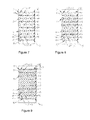
- Fig. 1 shows a pin jig required for manufacturing this endoluminal stent.
- This pin jig comprises a mandrel 1 with round holes and pins 2 inserted into the round holes.
- On the mandrel1 there are eight round holes in each circle along the circumferential direction of the side wall, the azimuth angle of round holes on two adjacent circumferences are staggered, and each of the pins 2 is fixed into one round hole of the mandrel 1, respectively.
- Fig. 2 is a schematic diagram of the mandrel 1 of Fig. 1 , with the lateral surface thereof unfolded into a plane. The pins 2 are distributed evenly along the circumferences, and each of the circumferences is unfolded into a straight line.
- This mandrel has a total of ten circumferences in the axial direction and the distances between the adjacent circumferences are the same. Although this mandrel has ten circumferences, depending upon demands, the number of circumferences on the mandrel may be reduced to four. There may also be more than ten circumferences, and the distances between the circumferences may be different.
- the two pins 2 at two ends of a same circumference are shown repeatedly. Actually, the two pins shown are the same pin 2, because of the periodical array of the pins 2 on the circumferences. As shown in Fig. 2 , eight pins 2 are arrayed on each circumference.
- k is an odd number, it is better to stagger the pins respectively on two adjacent circumferences.
- a pin on one circumference faces a middle point of a connecting line between two adjacent pins on an adjacent circumference.
- the braiding of the grid will be uniform, just like the one in this embodiment.
- k is an even number, it is better to enable pins respectively on two adjacent circumferences to be aligned to each other and arrayed in a matrix, in order to make the braided grid uniform.
- a nickel-titanium wire having a diameter of 0.05 inches is used for braiding, and it may be replaced by a braiding wire made of other materials, for example, stainless steel wire.
- a first group of grids is braided first.
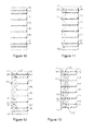
- a first group of crest and trough (crest refers to the highest point of a wave band, and trough refers to the lowest point of a wave band) of a first wave band is winding in the axial direction, starting from the pin 3 on the first circumference 41; the filament is wrapped around the pin 4 on the second circumference 42 to form a crest; and then the filament is wrapped around the pin 5 on the third circumference 43 to form a trough. So far, the winding of the first group of crest and trough of the first wave band is completed.
- the nickel-titanium wire passes through the third circumference 44 and the fourth circumference 45 along a zigzag path in the axial direction according to the method mentioned above, so as to form a second group of crest and trough; then passes through the fifth circumference 46 and the sixth circumference 47 to form a third group of crest and trough; and then passes through the seventh circumference 48 and the eighth circumference 49 to form a fourth group of crest and trough.
- the braiding filament is wrapped around the pin 8 on the tenth circumference 50 to end the winding of the first wave band in the axial direction.
- the crests and troughs on one wave band are alternately arrayed, with all crests on one side of this wave band and all troughs on the other side of this wave band.
- crests are formed at positions of the pins 4 and 8 and troughs are formed at positions of the pins 5 and 6.
- the nickel-titanium wire from the pin 8 is wrapped around the pin 9 to start the winding of a first group of crest and trough of a second wave band.
- One trough of the second wave band is intersected with one crest in the first wave band at the position of the pin 7, and the intersected nickel-titanium wires are intertwined and fixed together at the position of the pin 7 to form one fixed cross-linking point where the braiding wires are fixed together, not capable of moving with respect to each other.
- Fig. 5 is a schematic diagram showing that nickel-titanium wires, intersecting in the proximity of the pin 7, are intertwined and fixed to each other.
- the nickel-titanium wires all change their directions after being intersected with each other, an included angle between the changed direction and the original trend is formed.
- the included angle is preferably between 60°and 120° and kept consistent.
- the winding of other crests and troughs of the second wave band is completed according to the same method.
- a nickel-titanium wire reaches the position of the pin 10 on the first circumference 41, troughs of the second wave band are respectively intersected with crests of the first wave band to form fixed cross-linking points, and nickel-titanium wires at the intersecting positions are intertwined together.
- the distance between the pin 3 and the pin 10 is three times of that between adjacent pins. That is, there are two pins reserved and unused between the pin 3 and the pin 10.
- the winding of the third wave band is started from the position of the pin 10, and the winding of the third, fourth and fifth wave bands is completed according to the same method.
- the nickel-titanium wire reaches the position of the pin 11 on the tenth circumference 50 to form the first group of grids, as shown in Fig. 6 .
- the braiding of the second group of grids is started.
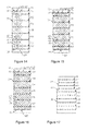
- the winding of a sixth wave band is started from the pin 11, and a first crossing point 12 between the sixth wave band and the first wave band is formed in the proximity of the pin 11. Braiding filaments passing through this crossing point are overlapped here without changing their original trends and capable of moving with respect to each other.
- the nickel-titanium wire of the sixth wave band meets the nickel-titanium wire of the first wave band for the first time, the nickel-titanium wire of the sixth wave band overlies the nickel-titanium wire of the first wave band, and the nickel-titanium wire of the sixth wave band and the nickel-titanium wire of the first wave band may move with respect to each other in the proximity of the first crossing point 12. Then, the nickel-titanium wire is wrapped around the pin 13 of the ninth circumference 49 to form a second crossing point 14 in the proximity of the pin 13.
- the nickel-titanium wire of the sixth wave band is overlapped with the nickel-titanium wire of the first wave band for the second time and passes underneath the nickel-titanium wire of the first wave band.
- This step is repeated, the nickel-titanium wire of the sixth wave band is crossed with the nickel-titanium wire of the second wave band for many times and alternately overlies and underlies the nickel-titanium wire of the second wave band, and when the nickel-titanium wire of the sixth wave band reaches the pin 15 on the first circumference 41, the winding of the sixth wave band is completed according to the method mentioned above.
- the sixth wave band is interwoven with the first waveband, and both extend in a same planar region; and the sixth wave band and the second wave band have a similar shape, and the two extend in parallel and are spaced a certain distance apart.
- the pin 3 is adjacent to the pin 15, while a pin is reserved and unused between the pin 15 and the pin 10.
- the winding of the seventh wave band is started from the pin 15.
- the nickel-titanium wire of the seventh wave band is intersected with, and alternately overlies and underlies the nickel-titanium filament of the second wave band repeatedly, to be interwoven with the second wave band.
- the seventh, eighth, ninth and tenth wave bands are wound according to the method mentioned above, as shown in Fig. 8 .
- the troughs of the seventh wave band are intertwined with corresponding crests of the sixth wave band
- the troughs of the eighth wave band are intertwined with corresponding crests of the seventh wave band, and so forth.
- the sixth, seventh, eighth, ninth and tenth wave bands are connected to form a second group of grids.
- the braiding of a third group of grids is started.
- the winding of the eleventh wave band is started from the position of the pin 16, and the winding of the eleventh, twelfth, thirteenth, fourteenth, fifteenth and sixteenth wave bands is completed according to the method mentioned above.
- the position of the pin 13 is not only the ending point of the sixteenth wave band, but also the starting point of the first wave band.
- the nickel-titanium wire extending from the tail of the sixteenth wave band is braided, intertwined and fixed with the nickel-titanium wire of the first wave band to form the closed third group of grids.
- the braiding of the whole stent is finished. Therefore, the number of wave bands is exactly twice of the number of the pins.
- Those wave bands respectively form three groups of grids and are intersected with each other, so as to form a stent with uniform and dense grids.
- the tubular grid of the endoluminal stent includes a plurality of crossing segments connected to each other in the axial direction.
- Each of the crossing segments is tubular, and there is an annular and closed boundary between two adjacent crossing segments.
- the grid points of each crossing segment are crossing points.
- All the cross-linking points are distributed on boundaries between the crossing segments, and there are nk-1 or nk+1 cross-linking points on each of the boundaries, where, both n and k are natural numbers, n ⁇ 3 and k ⁇ 2.
- cross-linking points on the boundaries are fixed cross-linking points.
- the closed-ring structure of the boundaries and the fixed cross-linking points will produce a larger radial support force.
- the number of crossing points of each crossing segment is substantially an integral multiple of that of cross-linking points of each boundary.
- many crossing points and fixed cross-linking points may be evenly distributed in alternant regions respectively, such an endoluminal stent has excellent performance in many aspects such as axial shortening, radial support strength and flexibility.
- endoluminal stent After braiding, together with the mandrel, and finally take the stent off from the mandrel.
- An endoluminal stent braided from nickel-titanium wires is properly thermally treated to have super-elasticity.
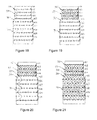
- the pins 2 on the mandrel are arrayed on eight circumferences, respectively, with eight pins 2 on each of the circumferences, and the pins 2 respectively on two adjacent circumferences are staggered.
- the spacing between the first circumference 51 and the second circumference 52 at one end is equal to that between the seventh circumference 57 and the eighth circumference 58 at the other end, and the axial distance between two adjacent circumferences of the rest circumferences is twice of that between two adjacent circumferences at either end.
- the distance between the second circumference 52 and the third circumference 53, the distance between the fourth circumference 54 and the fifth circumference 55, and the distance between the sixth circumference 56 and the seventh circumference 57 are all equal.
- a nickel-titanium wire having a diameter of 0.05 inches is also used for braiding, and three groups of grids, connected to each other, are interwoven from sixteen wave bands.
- a first group of crest and trough of a first wave band is wound in the axial direction, starting from the pin 17 on the first circumference 51, with the filament wound around the pin 18 on the second circumference 52 and then around the pin 19 on the third circumference 53, to finish the winding of the first group of crest and trough of the first wave band.
- the nickel-titanium wire is wound along a zigzag path in the axial direction according to the method mentioned above, wound around and terminating at the pin 20 on the eighth circumference 58, to complete the axial winding of the first wave band.
- the bending angle of the nickel-titanium wire at each of the pins is substantially equal to that of the nickel-titanium wire at a corresponding pin as shown in Fig. 3 , but due to the distance between the circumference 52 and the circumference 53 being double that of the distance between the circumference 51 and the circumference 52, the length of the nickel-titanium wire between the pin 18 and the pin 19 is double that of the nickel-titanium wire between the pin 17 and the pin 18.
- the stent is divided into a plurality of crossing segments connected to each other, and the distance between two adjacent circumferences defines the length of one crossing segment therebetween.
- a shorter crossing segment at one end of the endoluminal stent is braided through pins on the circumference 51 and circumference 52, five longer crossing segments in the middle of the endoluminal stent are braided through pins on and between the circumference 52 and circumference 57, and a shorter crossing segment at the other end of the endoluminal stent is braided through pins on the circumference 57 and circumference 58.
- the pin 19 on the circumference 53 may be staggered with the pin 17 on the circumference 51 by a length unit as shown in Fig. 11 or by 1.5 times or 2 times of the length unit (not shown), in order to ensure substantially uniform grids of crossing segments with different length.
- the nickel-titanium wire from the pin 20 is wound around the pin 21 to start the winding of a first group of crest and trough of a second wave band.
- the nickel-titanium wire of the second wave band and the nickel-titanium wire of the first wave band form a first crossing point 22.
- the nickel-titanium wire of the second wave band overlies the nickel-titanium wire of the first wave band.
- the nickel-titanium wire of the second wave band and the nickel-titanium wire of the first wave band form a second crossing point 23.
- the nickel-titanium wire of the second wave underlies the nickel-titanium wire of the first wave band. This step is repeated; the nickel-titanium wire of the second wave band is intersected with the nickel-titanium wire of the first wave band repeatedly, and alternately overlies and underlies the nickel-titanium wire of the first wave band.
- the nickel-titanium wire is finally wound around the pin 24 on the circumference 51 according to the above winding method, to finish the winding of the second wave band.
- the braiding method as shown in Fig. 4 is useful for increasing the radial support force and for reducing the shortening.
- the winding of the third wave band, fourth wave band and fifth wave band is completed according to the method for winding the first wave band and second wave bands.
- nickel-titanium wire is wound around the pin 25 on the circumference 58, and the first, second, third, fourth and fifth wave bands are interwoven to form the first group of grids, as shown in Fig. 13 .
- the braiding of the second group of grids is started.
- the winding of a sixth wave band is started from the position of the pin 25, and a trough of the sixth wave band is intersected with a crest of the first wave band to form a fixed cross-linking point, and the intersected nickel-titanium wires are intertwined at the position of the pin 26.
- each of the troughs of the sixth wave band is intersected with one corresponding crest of the first wave band at the position of a corresponding pin to form a fixed cross-linking point, and the nickel-titanium wires here are intertwined.
- the sixth wave band has a shape similar to that of the fourth wave band, and the sixth wave band and the fourth wave band extend in parallel with a certain distance between them.
- a plurality of crossing points are formed between the sixth wave band and respective the third wave band and the fifth wave band. Therefore, there are a plurality of fixed cross-linking points formed between the sixth wave band and the first wave band in the first group of grids so that a firm joint may be formed; furthermore, there are a plurality of crossing points between the sixth wave band and the first group of grids so that they may be interwoven uniformly together.
- the winding of the seventh wave band is started from the position of the pin 27.
- Each trough of the seventh wave band is intersected with a corresponding crest of the second wave band at a corresponding pin, where a fixed cross-linking point is formed.
- a plurality of crossing points are formed between the seventh wave band and respective the fourth wave band and the sixth wave band, and the seventh wave band and the second wave band form a relative firm connection.
- the winding of the eighth, ninth and tenth wave bands is continued.
- the sixth, seventh, eighth, ninth and tenth wave bands are interwoven to form the second group of grids, and each of the wave bands is interwoven with the first group of grids, respectively.
- a wave band of the second group of grids and a wave band of the first group of grids are connected in pair to form a plurality of fixed cross-linking points, such as the eighth wave band and the third wave band, the ninth wave band and the fourth wave band, and the tenth wave band and the fifth wave band.
- Each of the connections may be accomplished by a pin where a trough of a wave band of the second group of grids is intertwined with a crest of a wave band of the first group of grids to form a fixed cross-linking point to be wound together.
- the second group of grids and the first group of grids form a firm multi-point connection, thereby increasing the radial support force and reducing the axial shortening of the stent.
- each trough of the eleventh wave band is respectively intersected with a corresponding crest of the sixth wave band at a corresponding pin to form a fixed cross-linking point
- each trough of the twelfth wave band is respectively intersected with a corresponding crest of the seventh wave band at a corresponding pin to form a fixed cross-linking point
- the eleventh wave band and the twelfth wave band are respectively interwoven with other wave bands of the second group of grids to form a plurality of crossing points.
- the plurality of fixed cross-linking points formed by the eleventh wave band and the sixth wave band are fixed by intertwining, and the plurality of fixed cross-linking points formed by the twelfth wave band and the seventh wave band are fixed by intertwining, so that the third group of grids and the second group of grids form a firm and uniform connection.
- the braiding of the third group of grids is continued from the position of the pin 28, and the winding of the thirteenth, fourteenth, fifteenth and sixteenth wave bands is completed.
- the nickel-titanium wire at the tail of the sixteenth wave band is wound and fixed with the nickel-titanium wire of the first wave band, and the braiding of the whole stent is finished.
- the third group of grids is overlapped with the second group of grids and also with the first group of grids.
- the thirteenth and eighth wave bands, the fourteenth and third wave bands, the fifteenth and fourth wave bands, and the sixteenth and fifth wave bands are respectively intertwined in pair to form a plurality of fixed cross-linking points.
- a plurality of fixed cross-linking points are formed by a wave band of the first group of grids being intertwined with a wave band of the second group of grids and with a wave band of the third group of grids respectively
- a plurality of fixed cross-linking points are formed by a wave band of the second group of grids being intertwined with a wave band of the first group of grids and with a wave band of the third group of grids respectively.
- the three groups of grids are uniformly overlapped with each other to form an overall closed grid.
- the three groups of grids may form a uniform and firm connection of a plurality of fixed cross-linking points, and the whole grid has good long-term stability.
- the three groups of grids may slide relatively to each other at those crossing points.
- the whole grid exhibits good short-term variability, i.e., good flexibility.
- Fig. 17 is a schematic diagram of a mandrel for manufacturing an endoluminal stent of this embodiment, with the lateral surface unfolded.
- This mandrel differs from the mandrel of the first embodiment in that this mandrel includes two cylindrical segments having different diameters, i.e., a small cylindrical segment 29 having a smaller diameter and a large cylindrical segment 31 having a larger diameter, which are connected to each other by a tapered segment 30 to form a mandrel with three segments as a whole.
- the shape of this mandrel may vary, for example, a multi-segment structure having an outer diameter varying like a trapezoid, a structure having a bell mouth at one or two ends, and a continuously tapered structure.
- the same nickel-titanium wire as the first embodiment is used.
- the circumferences 61, 62, 63, 64 are all on the small cylindrical segment 29, the braiding is started from the pin 32 on the circumference 61, and the braiding of the head segment of the stent is first finished on the small cylindrical segment 29 according to the same method as the first embodiment.
- the tapered segment 30 is arranged between the circumference 64 and the circumference 65, and the circumferences 65, 66, 67, 68, 69 and 70 are all on the large cylindrical segment 31.
- a nickel-titanium wire is passed out from the position of the pin 33 on the circumference 64, and the braiding of the tail of the stent is started on the tapered segment 30 and the large cylindrical segment 31.
- the nickel-titanium wire of the tail segment of the stent is wound around each of the pins on the circumference 64, the nickel-titanium wire is further intertwined or interlocked with the nickel-titanium wire of the head segment of the stent around this pin.
- a cross-linking point is formed and the connection between the head segment and the tail segment of the stent is relatively loosened, a fixed cross-linking point is formed if the wires are intertwined, and the stent is firmer.
- the resulting laddered endoluminal stent is shown in Fig. 21 , the head segment of the stent has a smaller diameter and the tail segment of the stent includes a tapered transition segment and a segment having a larger diameter.
- the same pin jig and nickel-titanium wire as the first embodiment are used.
- the winding of the first wave band in the axial direction is completed according to the same method as the first embodiment, and then the winding of the second wave band is started.
- troughs of the second wave band are overlapped with crests of the first wave band, and the two are intertwined to form fixed cross-linking points.
- troughs of the second wave band are merely hooked up with crests of the first wave band to form a non-fixed cross-linking point, i.e., the two are interlocked, without being intertwined together.
- the troughs and the crests may move relative to each other in one-way, but not be capable of disconnecting from each other.
- the connecting points of the two wave bands are formed by interlocking and intertwining alternately, i.e., the alternate distribution of fixed cross-linking points and non-fixed cross-linking points. So far, the braiding of the second wave segment is completed.
- the winding of the rest wave bands is completed according to the way mentioned above.
- Each of the pins corresponds to one cross-linking point, and interlocking and intertwined are substantially alternately and uniformly distributed for all connecting points.
- the intertwined connecting points and the interlocked connecting points are alternately arrayed; and along the circumferential direction, the intertwined connecting points and the interlocked connecting points are also alternately arrayed; and the resulting stent is shown in Fig. 23 .
- the endoluminal stent made according to this method has a better flexibility than stents made by purely intertwined wires. In addition, good axial shortening and uniform radial support force may be retained.
- circumferential wave bands are wound generally, and closed-ring grids are also used for increasing the radial support force.
- closed-ring grids are also used for increasing the radial support force.
- endoluminal stent is likely to stack up and thus be shortened, and is disadvantageous for recovery to the original shape.
- the addition of fixed cross-linking points to the circumferential wave bands will increase the radial strength of the the endoluminal stent to a point where it is difficult to compress the stent into the sheath, which is disadvantageous for releasing and recovery of the endoluminal stent.
- the advantages of the endoluminal stent of the present invention depend on the use of axial wave bands together with the inherited coherent advantages of the closed-ring braided endoluminal stent. For example, repeated positioning may be realized, that is, the stent may be withdrawn into the sheath after having been partially released, then be released again after adjustment of its position. On the other hand, the shortening is reduced so that the stent is unlikely to have displacement during the release process, thereby resulting in accurate positioning and easy control. Furthermore, both the flexibility and the axial strength are improved, so that the stent may bear a large bending angle without kinking or losing the radial support force. Thus, the stent may be implanted into various tortuous vasculatures.
- the fixed cross-linking points are distributed on the circumference, thereby ensuring the radial support strength of the endoluminal stent; and crossing points are distributed in different crossing segments, thereby facilitating the improvement of the flexibility of the endoluminal stent.
- the crossing points and the fixed cross-linking points are alternately distributed, and there are more crossing points than fixed cross-linking points, so the density of the grids are enhanced and the stability of the structure is thus improved.
- the coverage to the artery atherosclerotic plaque is increased, the tubular grid is allowed to be deformed appropriately, the stress and the friction force are dispersed evenly, and the shortening, the flexibility and the radial support strength are balanced.
- the self-expandable endoluminal stent having a diameter of 4-12 millimeters, provided by the present invention
- the length of the endoluminal stent is increased by only 12-18%.
- the self-expanding endoluminal stent having a diameter of 8 millimeters is compressed into a sheath having an inner diameter of about 3 millimeters, the length thereof is increased by less than 40%, and the corresponding shortening is about 30%.
- the self-expanding endoluminal stent made according to the common braiding method in the prior art has an elongation percentage of about 100% under the same conditions and the corresponding shortening is about 50%.
- the shortening of the endoluminal stent of the present invention when released from the sheath is significantly reduced, which is beneficial for the controllability of operations and accuracy of positioning.
Applications Claiming Priority (2)
| Application Number | Priority Date | Filing Date | Title |
|---|---|---|---|
| CN201210443878.3A CN102973341B (zh) | 2012-11-08 | 2012-11-08 | 一种编织的自膨式管腔支架及其制作方法 |
| PCT/CN2013/086599 WO2014071837A1 (fr) | 2012-11-08 | 2013-11-06 | Endoprothèse endoluminale autoexpansible tressée |
Publications (3)
| Publication Number | Publication Date |
|---|---|
| EP2918251A1 true EP2918251A1 (fr) | 2015-09-16 |
| EP2918251A4 EP2918251A4 (fr) | 2016-08-24 |
| EP2918251B1 EP2918251B1 (fr) | 2018-08-29 |
Family
ID=47847885
Family Applications (1)
| Application Number | Title | Priority Date | Filing Date |
|---|---|---|---|
| EP13854131.3A Active EP2918251B1 (fr) | 2012-11-08 | 2013-11-06 | Endoprothèse endoluminale autoexpansible tressée et methode de production |
Country Status (4)
| Country | Link |
|---|---|
| US (1) | US10251763B2 (fr) |
| EP (1) | EP2918251B1 (fr) |
| CN (1) | CN102973341B (fr) |
| WO (1) | WO2014071837A1 (fr) |
Cited By (5)
| Publication number | Priority date | Publication date | Assignee | Title |
|---|---|---|---|---|
| WO2016114039A1 (fr) * | 2015-01-13 | 2016-07-21 | 日本ライフライン株式会社 | Endoprothèse et greffe d'endoprothèse |
| WO2019025265A1 (fr) * | 2017-08-01 | 2019-02-07 | Novatech Sa | Stent |
| CN111132638A (zh) * | 2017-07-27 | 2020-05-08 | 波士顿科学国际有限公司 | 用于形成具有抗迁移特征的支架的可调节芯轴 |
| US11517319B2 (en) | 2017-09-23 | 2022-12-06 | Universität Zürich | Medical occluder device |
| US11944315B2 (en) | 2019-09-26 | 2024-04-02 | Universität Zürich | Left atrial appendage occlusion devices |
Families Citing this family (24)
| Publication number | Priority date | Publication date | Assignee | Title |
|---|---|---|---|---|
| CN102973341B (zh) * | 2012-11-08 | 2015-06-17 | 先健科技(深圳)有限公司 | 一种编织的自膨式管腔支架及其制作方法 |
| KR101488972B1 (ko) * | 2014-09-12 | 2015-02-02 | (주)시지바이오 | 스텐트 및 이 스텐트의 제조방법 |
| KR101696810B1 (ko) * | 2015-02-04 | 2017-02-01 | 주식회사 엠아이텍 | 연결용 스텐트 및 그의 제조방법 |
| KR101728319B1 (ko) * | 2015-04-15 | 2017-04-19 | 주식회사 엠아이텍 | 스텐트 제조방법 |
| CN105250058B (zh) * | 2015-10-26 | 2017-08-29 | 先健科技(深圳)有限公司 | 管腔编织支架 |
| KR101785042B1 (ko) * | 2016-02-15 | 2017-10-12 | (주) 태웅메디칼 | 형상기억합금 와이어를 이용한 스텐트의 제조방법과 이에 의해 제조한 스텐트 및 이를 제조하기 위한 지그 |
| US10390944B2 (en) * | 2016-04-13 | 2019-08-27 | Hlt, Inc. | Braided support structure |
| EP3466376A4 (fr) * | 2016-06-03 | 2020-01-29 | Puyi (Shanghai) Biotechnology Co., Ltd | Procédé de tissage pour stents de sinus nasal et stents similaires. |
| AU2017349575B2 (en) * | 2016-10-27 | 2022-11-17 | Rapid Medical Ltd. | Woven wire intraluminal device |
| WO2018110736A1 (fr) * | 2016-12-15 | 2018-06-21 | 주식회사 비씨엠 | Procédé de fabrication d'un stent médical ayant des parties d'extrémité à résistance renforcée, et stent fabriqué à l'aide de celui-ci |
| CN107604528A (zh) * | 2017-10-10 | 2018-01-19 | 东华大学 | 交叉转动式径向缩胀管织物及其制备方法与用途 |
| CN107928845A (zh) * | 2017-12-04 | 2018-04-20 | 成都迈德克科技有限公司 | 一种编织血管支架及制备方法 |
| DE102019101238B8 (de) * | 2019-01-17 | 2020-08-06 | Stebo Sondermaschinenbau GmbH & Co. KG | Verfahren zum Herstellen eines geflochtenen Einfadenstents, Vorrichtung und Flechtkern hierfür sowie geflochtener Einfadenstent |
| WO2021005931A1 (fr) * | 2019-07-09 | 2021-01-14 | 株式会社Pentas | Endoprothèse et procédé de fixation pour fils d'élément dans une endoprothèse |
| US11672661B2 (en) | 2019-08-22 | 2023-06-13 | Silara Medtech Inc. | Annuloplasty systems and methods |
| CN111118729B (zh) * | 2020-01-10 | 2021-06-01 | 江苏唯德康医疗科技有限公司 | 一种支架编织方法及使用该方法制成的支架 |
| CN112331383A (zh) * | 2020-10-14 | 2021-02-05 | 南京信宁电缆有限公司 | 一种防水抗拉导气电缆 |
| EP4255356A1 (fr) | 2020-12-02 | 2023-10-11 | Boston Scientific Scimed, Inc. | Endoprothèse à caractéristiques de déploiement améliorées |
| CN112676499B (zh) * | 2020-12-07 | 2022-10-11 | 北京泰杰伟业科技有限公司 | 一种血管支架制造用模具及其加工设备 |
| CN114948362A (zh) * | 2021-02-16 | 2022-08-30 | 奥林巴斯株式会社 | 支架 |
| CN115844606A (zh) * | 2021-09-24 | 2023-03-28 | 微创优通医疗科技(嘉兴)有限公司 | 用于肠道的支架及其编织方法 |
| CN115976731B (zh) * | 2023-03-21 | 2023-06-20 | 海底鹰深海科技股份有限公司 | 光纤网及其编织方法 |
| CN115976730A (zh) * | 2023-03-21 | 2023-04-18 | 北京爱霖医疗科技有限公司 | 支架及其编织方法、编织胎具 |
| CN116350411A (zh) * | 2023-04-11 | 2023-06-30 | 江苏唯德康医疗科技有限公司 | 一种支架编织方法及使用该方法编织的支架 |
Family Cites Families (32)
| Publication number | Priority date | Publication date | Assignee | Title |
|---|---|---|---|---|
| US4817613A (en) * | 1987-07-13 | 1989-04-04 | Devices For Vascular Intervention, Inc. | Guiding catheter |
| US5035706A (en) * | 1989-10-17 | 1991-07-30 | Cook Incorporated | Percutaneous stent and method for retrieval thereof |
| US5116365A (en) * | 1991-02-22 | 1992-05-26 | Cordis Corporation | Stent apparatus and method for making |
| US5366504A (en) * | 1992-05-20 | 1994-11-22 | Boston Scientific Corporation | Tubular medical prosthesis |
| US5476508A (en) * | 1994-05-26 | 1995-12-19 | Tfx Medical | Stent with mutually interlocking filaments |
| DE4424242A1 (de) * | 1994-07-09 | 1996-01-11 | Ernst Peter Prof Dr M Strecker | In den Körper eines Patienten perkutan implantierbare Endoprothese |
| RU2157146C2 (ru) * | 1995-06-13 | 2000-10-10 | ВИЛЬЯМ КУК Европа, A/S | Устройство для имплантации в сосудах и полых органах (его варианты) |
| US5718159A (en) * | 1996-04-30 | 1998-02-17 | Schneider (Usa) Inc. | Process for manufacturing three-dimensional braided covered stent |
| US6520983B1 (en) * | 1998-03-31 | 2003-02-18 | Scimed Life Systems, Inc. | Stent delivery system |
| US6187036B1 (en) * | 1998-12-11 | 2001-02-13 | Endologix, Inc. | Endoluminal vascular prosthesis |
| DE19954166A1 (de) * | 1999-11-10 | 2001-05-17 | Inst Textil & Faserforschung | Flächiges Implantat, Verfahren zu seiner Herstellung und Verwendung in der Chirurgie |
| US6585759B1 (en) * | 1999-12-16 | 2003-07-01 | Israel Aircraft Industries Ltd. | Method and apparatus for manufacturing medical support devices |
| US20060265052A1 (en) * | 2001-03-29 | 2006-11-23 | Isis Innovation Limited | Deployable stent |
| KR100457630B1 (ko) * | 2001-04-04 | 2004-11-18 | (주) 태웅메디칼 | 형상기억합금을 이용한 가변상태 유지형 확장기구의제조방법과 이에 의해 제조된 확장기구 |
| JP4043216B2 (ja) * | 2001-10-30 | 2008-02-06 | オリンパス株式会社 | ステント |
| US6939369B2 (en) * | 2002-04-03 | 2005-09-06 | Cook Incorporated | Intraluminal graft assembly and vessel repair system |
| US7195648B2 (en) * | 2002-05-16 | 2007-03-27 | Cordis Neurovascular, Inc. | Intravascular stent device |
| US7001425B2 (en) * | 2002-11-15 | 2006-02-21 | Scimed Life Systems, Inc. | Braided stent method for its manufacture |
| US7344559B2 (en) * | 2003-08-25 | 2008-03-18 | Biophan Technologies, Inc. | Electromagnetic radiation transparent device and method of making thereof |
| FR2865926B1 (fr) * | 2004-02-11 | 2006-05-12 | Perouse Laboratoires | Prothese tubulaire. |
| US20050192581A1 (en) * | 2004-02-27 | 2005-09-01 | Molz Fred J. | Radiopaque, coaxial orthopedic tether design and method |
| US20050288775A1 (en) * | 2004-06-24 | 2005-12-29 | Scimed Life Systems, Inc. | Metallic fibers reinforced textile prosthesis |
| WO2007002933A2 (fr) * | 2005-06-28 | 2007-01-04 | Stout Medical Group, Inc. | Microstructures en couches minces destinees a des applications cardiovasculaires |
| KR100633020B1 (ko) * | 2005-07-15 | 2006-10-11 | 주식회사 스텐다드싸이텍 | 스텐트 및 그의 제작 방법 |
| CN201150578Y (zh) * | 2007-12-26 | 2008-11-19 | 上海康德莱企业发展集团有限公司 | 一种编织血管支架 |
| US8151682B2 (en) * | 2009-01-26 | 2012-04-10 | Boston Scientific Scimed, Inc. | Atraumatic stent and method and apparatus for making the same |
| DE102009042121B3 (de) * | 2009-09-18 | 2011-04-21 | Acandis Gmbh & Co. Kg | Medizinisches Gerät zum Einführen in ein Körperhohlorgan |
| US20120191177A1 (en) * | 2011-01-20 | 2012-07-26 | Medtronic Vascular, Inc. | Tubular Helical Stent With Rotatable Connections and Method of Making |
| US8511214B2 (en) * | 2011-04-21 | 2013-08-20 | Aga Medical Corporation | Tubular structure and method for making the same |
| US20130289690A1 (en) * | 2011-11-01 | 2013-10-31 | Hira V. Thapliyal | Personalized prosthesis and methods of use |
| CN202982316U (zh) * | 2012-11-08 | 2013-06-12 | 先健科技(深圳)有限公司 | 一种编织的自膨式管腔支架 |
| CN102973341B (zh) * | 2012-11-08 | 2015-06-17 | 先健科技(深圳)有限公司 | 一种编织的自膨式管腔支架及其制作方法 |
-
2012
- 2012-11-08 CN CN201210443878.3A patent/CN102973341B/zh active Active
-
2013
- 2013-11-06 EP EP13854131.3A patent/EP2918251B1/fr active Active
- 2013-11-06 WO PCT/CN2013/086599 patent/WO2014071837A1/fr active Application Filing
- 2013-11-06 US US14/441,221 patent/US10251763B2/en active Active
Cited By (11)
| Publication number | Priority date | Publication date | Assignee | Title |
|---|---|---|---|---|
| WO2016114039A1 (fr) * | 2015-01-13 | 2016-07-21 | 日本ライフライン株式会社 | Endoprothèse et greffe d'endoprothèse |
| CN111132638A (zh) * | 2017-07-27 | 2020-05-08 | 波士顿科学国际有限公司 | 用于形成具有抗迁移特征的支架的可调节芯轴 |
| CN111132638B (zh) * | 2017-07-27 | 2022-03-29 | 波士顿科学国际有限公司 | 用于形成具有抗迁移特征的支架的可调节芯轴 |
| WO2019025265A1 (fr) * | 2017-08-01 | 2019-02-07 | Novatech Sa | Stent |
| CN110545762A (zh) * | 2017-08-01 | 2019-12-06 | 诺瓦泰克股份有限公司 | 支架 |
| KR20200010380A (ko) * | 2017-08-01 | 2020-01-30 | 노바테크 에스에이 | 스텐트 |
| US10980988B2 (en) | 2017-08-01 | 2021-04-20 | Novatech Sa | Stent |
| DE102017117439B4 (de) * | 2017-08-01 | 2021-05-20 | Novatech Sa | Stent |
| CN110545762B (zh) * | 2017-08-01 | 2021-09-24 | 诺瓦泰克股份有限公司 | 支架 |
| US11517319B2 (en) | 2017-09-23 | 2022-12-06 | Universität Zürich | Medical occluder device |
| US11944315B2 (en) | 2019-09-26 | 2024-04-02 | Universität Zürich | Left atrial appendage occlusion devices |
Also Published As
| Publication number | Publication date |
|---|---|
| EP2918251B1 (fr) | 2018-08-29 |
| CN102973341B (zh) | 2015-06-17 |
| EP2918251A4 (fr) | 2016-08-24 |
| CN102973341A (zh) | 2013-03-20 |
| US10251763B2 (en) | 2019-04-09 |
| US20160213498A1 (en) | 2016-07-28 |
| WO2014071837A1 (fr) | 2014-05-15 |
Similar Documents
| Publication | Publication Date | Title |
|---|---|---|
| US10251763B2 (en) | Braided self-expanding endoluminal stent and manufacturing method thereof | |
| US6241757B1 (en) | Stent for expanding body's lumen | |
| US9592137B2 (en) | Flexible stent | |
| JP4197762B2 (ja) | 分岐した脈管を処置するためのステントおよびステント移植片 | |
| JP5036116B2 (ja) | 血管内ステント | |
| EP3057540B1 (fr) | Endoprothèse vasculaire | |
| US20120239136A1 (en) | Flexible intraluminal stent | |
| JPH11128364A (ja) | 拡張可能な管腔内部人工器官 | |
| JPH09512460A (ja) | 医療用人工ステント及びその製造方法 | |
| JP2017533806A (ja) | ステントプロテーゼ | |
| US10449069B2 (en) | Stent | |
| CN202982316U (zh) | 一种编织的自膨式管腔支架 | |
| CN112089511A (zh) | 一种应用于锥形血管多重狭窄的自膨胀式锥形血管支架 | |
| US10905572B2 (en) | Stent | |
| WO2024067402A1 (fr) | Endoprothèse vasculaire | |
| AU2012201649B2 (en) | Flexible stent | |
| EP4248918A1 (fr) | Endoprothèse vasculaire périphérique, son procédé de fabrication et son application | |
| US10258488B2 (en) | Stent | |
| AU2014201135B2 (en) | Flexible stent |
Legal Events
| Date | Code | Title | Description |
|---|---|---|---|
| PUAI | Public reference made under article 153(3) epc to a published international application that has entered the european phase |
Free format text: ORIGINAL CODE: 0009012 |
|
| 17P | Request for examination filed |
Effective date: 20150601 |
|
| AK | Designated contracting states |
Kind code of ref document: A1 Designated state(s): AL AT BE BG CH CY CZ DE DK EE ES FI FR GB GR HR HU IE IS IT LI LT LU LV MC MK MT NL NO PL PT RO RS SE SI SK SM TR |
|
| AX | Request for extension of the european patent |
Extension state: BA ME |
|
| RIN1 | Information on inventor provided before grant (corrected) |
Inventor name: WANG, YONGSHENG |
|
| DAX | Request for extension of the european patent (deleted) | ||
| RA4 | Supplementary search report drawn up and despatched (corrected) |
Effective date: 20160722 |
|
| RIC1 | Information provided on ipc code assigned before grant |
Ipc: A61F 2/06 20060101ALI20160718BHEP Ipc: A61F 2/90 20130101AFI20160718BHEP |
|
| GRAP | Despatch of communication of intention to grant a patent |
Free format text: ORIGINAL CODE: EPIDOSNIGR1 |
|
| INTG | Intention to grant announced |
Effective date: 20180314 |
|
| GRAS | Grant fee paid |
Free format text: ORIGINAL CODE: EPIDOSNIGR3 |
|
| GRAA | (expected) grant |
Free format text: ORIGINAL CODE: 0009210 |
|
| AK | Designated contracting states |
Kind code of ref document: B1 Designated state(s): AL AT BE BG CH CY CZ DE DK EE ES FI FR GB GR HR HU IE IS IT LI LT LU LV MC MK MT NL NO PL PT RO RS SE SI SK SM TR |
|
| REG | Reference to a national code |
Ref country code: GB Ref legal event code: FG4D |
|
| REG | Reference to a national code |
Ref country code: CH Ref legal event code: EP |
|
| REG | Reference to a national code |
Ref country code: AT Ref legal event code: REF Ref document number: 1034267 Country of ref document: AT Kind code of ref document: T Effective date: 20180915 |
|
| REG | Reference to a national code |
Ref country code: IE Ref legal event code: FG4D |
|
| REG | Reference to a national code |
Ref country code: DE Ref legal event code: R096 Ref document number: 602013042903 Country of ref document: DE |
|
| REG | Reference to a national code |
Ref country code: NL Ref legal event code: MP Effective date: 20180829 |
|
| REG | Reference to a national code |
Ref country code: LT Ref legal event code: MG4D |
|
| PG25 | Lapsed in a contracting state [announced via postgrant information from national office to epo] |
Ref country code: NL Free format text: LAPSE BECAUSE OF FAILURE TO SUBMIT A TRANSLATION OF THE DESCRIPTION OR TO PAY THE FEE WITHIN THE PRESCRIBED TIME-LIMIT Effective date: 20180829 Ref country code: RS Free format text: LAPSE BECAUSE OF FAILURE TO SUBMIT A TRANSLATION OF THE DESCRIPTION OR TO PAY THE FEE WITHIN THE PRESCRIBED TIME-LIMIT Effective date: 20180829 Ref country code: LT Free format text: LAPSE BECAUSE OF FAILURE TO SUBMIT A TRANSLATION OF THE DESCRIPTION OR TO PAY THE FEE WITHIN THE PRESCRIBED TIME-LIMIT Effective date: 20180829 Ref country code: BG Free format text: LAPSE BECAUSE OF FAILURE TO SUBMIT A TRANSLATION OF THE DESCRIPTION OR TO PAY THE FEE WITHIN THE PRESCRIBED TIME-LIMIT Effective date: 20181129 Ref country code: SE Free format text: LAPSE BECAUSE OF FAILURE TO SUBMIT A TRANSLATION OF THE DESCRIPTION OR TO PAY THE FEE WITHIN THE PRESCRIBED TIME-LIMIT Effective date: 20180829 Ref country code: GR Free format text: LAPSE BECAUSE OF FAILURE TO SUBMIT A TRANSLATION OF THE DESCRIPTION OR TO PAY THE FEE WITHIN THE PRESCRIBED TIME-LIMIT Effective date: 20181130 Ref country code: FI Free format text: LAPSE BECAUSE OF FAILURE TO SUBMIT A TRANSLATION OF THE DESCRIPTION OR TO PAY THE FEE WITHIN THE PRESCRIBED TIME-LIMIT Effective date: 20180829 Ref country code: IS Free format text: LAPSE BECAUSE OF FAILURE TO SUBMIT A TRANSLATION OF THE DESCRIPTION OR TO PAY THE FEE WITHIN THE PRESCRIBED TIME-LIMIT Effective date: 20181229 Ref country code: NO Free format text: LAPSE BECAUSE OF FAILURE TO SUBMIT A TRANSLATION OF THE DESCRIPTION OR TO PAY THE FEE WITHIN THE PRESCRIBED TIME-LIMIT Effective date: 20181129 |
|
| REG | Reference to a national code |
Ref country code: AT Ref legal event code: MK05 Ref document number: 1034267 Country of ref document: AT Kind code of ref document: T Effective date: 20180829 |
|
| PG25 | Lapsed in a contracting state [announced via postgrant information from national office to epo] |
Ref country code: LV Free format text: LAPSE BECAUSE OF FAILURE TO SUBMIT A TRANSLATION OF THE DESCRIPTION OR TO PAY THE FEE WITHIN THE PRESCRIBED TIME-LIMIT Effective date: 20180829 Ref country code: HR Free format text: LAPSE BECAUSE OF FAILURE TO SUBMIT A TRANSLATION OF THE DESCRIPTION OR TO PAY THE FEE WITHIN THE PRESCRIBED TIME-LIMIT Effective date: 20180829 Ref country code: AL Free format text: LAPSE BECAUSE OF FAILURE TO SUBMIT A TRANSLATION OF THE DESCRIPTION OR TO PAY THE FEE WITHIN THE PRESCRIBED TIME-LIMIT Effective date: 20180829 |
|
| PG25 | Lapsed in a contracting state [announced via postgrant information from national office to epo] |
Ref country code: RO Free format text: LAPSE BECAUSE OF FAILURE TO SUBMIT A TRANSLATION OF THE DESCRIPTION OR TO PAY THE FEE WITHIN THE PRESCRIBED TIME-LIMIT Effective date: 20180829 Ref country code: CZ Free format text: LAPSE BECAUSE OF FAILURE TO SUBMIT A TRANSLATION OF THE DESCRIPTION OR TO PAY THE FEE WITHIN THE PRESCRIBED TIME-LIMIT Effective date: 20180829 Ref country code: IT Free format text: LAPSE BECAUSE OF FAILURE TO SUBMIT A TRANSLATION OF THE DESCRIPTION OR TO PAY THE FEE WITHIN THE PRESCRIBED TIME-LIMIT Effective date: 20180829 Ref country code: AT Free format text: LAPSE BECAUSE OF FAILURE TO SUBMIT A TRANSLATION OF THE DESCRIPTION OR TO PAY THE FEE WITHIN THE PRESCRIBED TIME-LIMIT Effective date: 20180829 Ref country code: EE Free format text: LAPSE BECAUSE OF FAILURE TO SUBMIT A TRANSLATION OF THE DESCRIPTION OR TO PAY THE FEE WITHIN THE PRESCRIBED TIME-LIMIT Effective date: 20180829 Ref country code: ES Free format text: LAPSE BECAUSE OF FAILURE TO SUBMIT A TRANSLATION OF THE DESCRIPTION OR TO PAY THE FEE WITHIN THE PRESCRIBED TIME-LIMIT Effective date: 20180829 Ref country code: PL Free format text: LAPSE BECAUSE OF FAILURE TO SUBMIT A TRANSLATION OF THE DESCRIPTION OR TO PAY THE FEE WITHIN THE PRESCRIBED TIME-LIMIT Effective date: 20180829 |
|
| PG25 | Lapsed in a contracting state [announced via postgrant information from national office to epo] |
Ref country code: SK Free format text: LAPSE BECAUSE OF FAILURE TO SUBMIT A TRANSLATION OF THE DESCRIPTION OR TO PAY THE FEE WITHIN THE PRESCRIBED TIME-LIMIT Effective date: 20180829 Ref country code: DK Free format text: LAPSE BECAUSE OF FAILURE TO SUBMIT A TRANSLATION OF THE DESCRIPTION OR TO PAY THE FEE WITHIN THE PRESCRIBED TIME-LIMIT Effective date: 20180829 Ref country code: SM Free format text: LAPSE BECAUSE OF FAILURE TO SUBMIT A TRANSLATION OF THE DESCRIPTION OR TO PAY THE FEE WITHIN THE PRESCRIBED TIME-LIMIT Effective date: 20180829 |
|
| REG | Reference to a national code |
Ref country code: DE Ref legal event code: R097 Ref document number: 602013042903 Country of ref document: DE |
|
| REG | Reference to a national code |
Ref country code: CH Ref legal event code: PL |
|
| PLBE | No opposition filed within time limit |
Free format text: ORIGINAL CODE: 0009261 |
|
| STAA | Information on the status of an ep patent application or granted ep patent |
Free format text: STATUS: NO OPPOSITION FILED WITHIN TIME LIMIT |
|
| GBPC | Gb: european patent ceased through non-payment of renewal fee |
Effective date: 20181129 |
|
| PG25 | Lapsed in a contracting state [announced via postgrant information from national office to epo] |
Ref country code: MC Free format text: LAPSE BECAUSE OF FAILURE TO SUBMIT A TRANSLATION OF THE DESCRIPTION OR TO PAY THE FEE WITHIN THE PRESCRIBED TIME-LIMIT Effective date: 20180829 Ref country code: LU Free format text: LAPSE BECAUSE OF NON-PAYMENT OF DUE FEES Effective date: 20181106 |
|
| 26N | No opposition filed |
Effective date: 20190531 |
|
| REG | Reference to a national code |
Ref country code: BE Ref legal event code: MM Effective date: 20181130 |
|
| REG | Reference to a national code |
Ref country code: IE Ref legal event code: MM4A |
|
| PG25 | Lapsed in a contracting state [announced via postgrant information from national office to epo] |
Ref country code: SI Free format text: LAPSE BECAUSE OF FAILURE TO SUBMIT A TRANSLATION OF THE DESCRIPTION OR TO PAY THE FEE WITHIN THE PRESCRIBED TIME-LIMIT Effective date: 20180829 Ref country code: LI Free format text: LAPSE BECAUSE OF NON-PAYMENT OF DUE FEES Effective date: 20181130 Ref country code: CH Free format text: LAPSE BECAUSE OF NON-PAYMENT OF DUE FEES Effective date: 20181130 |
|
| PG25 | Lapsed in a contracting state [announced via postgrant information from national office to epo] |
Ref country code: FR Free format text: LAPSE BECAUSE OF NON-PAYMENT OF DUE FEES Effective date: 20181130 Ref country code: IE Free format text: LAPSE BECAUSE OF NON-PAYMENT OF DUE FEES Effective date: 20181106 |
|
| PG25 | Lapsed in a contracting state [announced via postgrant information from national office to epo] |
Ref country code: BE Free format text: LAPSE BECAUSE OF NON-PAYMENT OF DUE FEES Effective date: 20181130 |
|
| PG25 | Lapsed in a contracting state [announced via postgrant information from national office to epo] |
Ref country code: GB Free format text: LAPSE BECAUSE OF NON-PAYMENT OF DUE FEES Effective date: 20181129 |
|
| PG25 | Lapsed in a contracting state [announced via postgrant information from national office to epo] |
Ref country code: MT Free format text: LAPSE BECAUSE OF NON-PAYMENT OF DUE FEES Effective date: 20181106 |
|
| PG25 | Lapsed in a contracting state [announced via postgrant information from national office to epo] |
Ref country code: TR Free format text: LAPSE BECAUSE OF FAILURE TO SUBMIT A TRANSLATION OF THE DESCRIPTION OR TO PAY THE FEE WITHIN THE PRESCRIBED TIME-LIMIT Effective date: 20180829 |
|
| PG25 | Lapsed in a contracting state [announced via postgrant information from national office to epo] |
Ref country code: PT Free format text: LAPSE BECAUSE OF FAILURE TO SUBMIT A TRANSLATION OF THE DESCRIPTION OR TO PAY THE FEE WITHIN THE PRESCRIBED TIME-LIMIT Effective date: 20180829 |
|
| PG25 | Lapsed in a contracting state [announced via postgrant information from national office to epo] |
Ref country code: HU Free format text: LAPSE BECAUSE OF FAILURE TO SUBMIT A TRANSLATION OF THE DESCRIPTION OR TO PAY THE FEE WITHIN THE PRESCRIBED TIME-LIMIT; INVALID AB INITIO Effective date: 20131106 Ref country code: CY Free format text: LAPSE BECAUSE OF FAILURE TO SUBMIT A TRANSLATION OF THE DESCRIPTION OR TO PAY THE FEE WITHIN THE PRESCRIBED TIME-LIMIT Effective date: 20180829 Ref country code: MK Free format text: LAPSE BECAUSE OF NON-PAYMENT OF DUE FEES Effective date: 20180829 |
|
| P01 | Opt-out of the competence of the unified patent court (upc) registered |
Effective date: 20230515 |
|
| PGFP | Annual fee paid to national office [announced via postgrant information from national office to epo] |
Ref country code: DE Payment date: 20231107 Year of fee payment: 11 |