EP2916658B1 - Backform für brot - Google Patents
Backform für brot Download PDFInfo
- Publication number
- EP2916658B1 EP2916658B1 EP13821165.1A EP13821165A EP2916658B1 EP 2916658 B1 EP2916658 B1 EP 2916658B1 EP 13821165 A EP13821165 A EP 13821165A EP 2916658 B1 EP2916658 B1 EP 2916658B1
- Authority
- EP
- European Patent Office
- Prior art keywords
- pan
- plate
- moulds
- hook
- cover
- Prior art date
- Legal status (The legal status is an assumption and is not a legal conclusion. Google has not performed a legal analysis and makes no representation as to the accuracy of the status listed.)
- Active
Links
Images





Classifications
-
- A—HUMAN NECESSITIES
- A21—BAKING; EDIBLE DOUGHS
- A21B—BAKERS' OVENS; MACHINES OR EQUIPMENT FOR BAKING
- A21B3/00—Parts or accessories of ovens
- A21B3/13—Baking-tins; Baking forms
- A21B3/135—Accessories, e.g. covers, handles
-
- A—HUMAN NECESSITIES
- A21—BAKING; EDIBLE DOUGHS
- A21B—BAKERS' OVENS; MACHINES OR EQUIPMENT FOR BAKING
- A21B3/00—Parts or accessories of ovens
- A21B3/13—Baking-tins; Baking forms
- A21B3/133—Baking-tins; Baking forms for making bread
- A21B3/134—Multiple bread pans
Definitions
- the present invention relates to a pan for baking bread on an industrial scale which has a plate acting as a cover and is, nevertheless, light and easy to handle.
- Pans are known for baking the type of bread known as pan loaf on an industrial scale. These pans comprise a plurality of baking moulds and, in many cases, a plate acting as a cover of the pan.
- Said plate acting as a cover is placed to avoid the upper part of the bread from becoming convex and thus obtaining, insofar as possible, a loaf of uniform square or rectangular section which is easy to handle. Nevertheless, it has been observed that, in practice, despite the use of the cover, the existing pans obtain a loaf which has many irregularities or bulges on its surface.
- pans are displaced empty along chains until reaching the production chain where the raw bread dough falls inside the moulds.
- pans are covered with said plate acting as a cover and they enter the fermentation process.
- the pans enter the oven to bake the dough.
- the bread dough may displace the plate that serves as a cover.
- plates or covers of a heavy weight (6 to 8 kg) which are not displaced with the thrust of the bread dough.
- these plates hinder fast heat transmission and are difficult to handle.
- US 2 071 845 A discloses a bread form embodying a rectangular form comprising three compartments, a cover and a spring clip.
- US 1 050 449 A discloses a pan for baking bread comprising a plurality of baking moulds, a plate acting as a cover, a structure and a fastening device.
- FR 1 166 787 A discloses a pan for making a bread comprising a plurality of baking moulds and a fastening hook hingedly joined to a weight and positioned on an outer frame of the pan.
- reinforcing structures that laterally cover the pan and give it resistance.
- these reinforcing structures also hinder the uniform transmission of heat in certain areas, which translates into a less homogeneous baking which negatively affects obtaining a regular shaped loaf.
- the objective of the present invention is that of resolving the aforementioned drawbacks, providing a pan for baking bread which has the advantages that will be described below.
- the present invention provides a pan for baking bread comprising a plurality of baking moulds, a plate acting as a cover of said moulds, and means to prevent the raising of said plate as the bread is baked inside said moulds, and it is characterized in that said means to prevent the raising of said plate comprise a fastening device associated to a structure of said pan, said fastening device including at least one hook which is hingedly joined to said structure, said hook being susceptible of fastening a portion of said plate when it tilts on said structure.
- the fastening device has the advantage that it effectively and safely prevents raising the cover without the need to resort to the use of plates with a heavy weight.
- the weight of the cover can be reduced to approximately 4 kg, which positively results in a large energy saving (quicker baking with smaller energy consumption).
- the pan is light and easy to handle.
- Another advantage of the pan claimed lies in the fact that said fastening device makes it possible to implement on an industrial scale an automatic process to place and remove the plate acting as a cover, externally actuating said hook or a counterweight that is associated with said hook. This positively leads to an improvement in the bread production yield.
- Said fastening hook is hingedly joined to a shaft of a structure of the pan which is interposed between two of said baking moulds and, advantageously, said structure is joined to the outer walls of two of the pan moulds.
- said plate acting as a cover comprises a lower portion which extends from the underside of said plate, said lower portion being interposed between two of said moulds in order that it can be gripped by said hook whilst said hook remains concealed under the plate in a closed position of the plate.
- said fastening hook is joined to a weight configured by way of a counterweight to tilt said hook automatically and fasten the plate, said same weight being susceptible of acting as a counterweight if actuated in the opposite direction to release the hook from the plate.
- the cover is very easy to place and remove which facilitates the industrial application of the pan.
- the weight acting as counterweight of the hook can be actuated in its lower part by a piston located under the transport chain of the pan to make the hook tilt and release the plate.
- the hook can be actuated in its upper part to make it tilt and release the plate.
- the plate comprises an upper portion arranged traversed in a plate groove, said hook being susceptible of fastening said upper portion when it tilts and traverses said groove.
- the structure of the pan whereto the fastening hook is joined comprises a piece which acts as a stop to limit the tilting movement of the weight and said hook.
- the upper edge of said hook has a curved profile to facilitate the sliding and upper placement of the plate acting as a cover.
- the plate acting as a cover comprises a plurality of recesses which act by way of a cover of each one of said moulds, each one of said recesses defining an insert "e" of the plate in the upper edge of the walls of said moulds.
- This insert "e” enables an adjustment between the plate and the walls of the moulds which makes it possible to accurately fix the dimensions of the internal cavity wherein the dough is housed during the baking. In this way, it guarantees that a loaf is obtained with uniform section, since the dough growth space is exactly delimited.
- said insert "e” facilitates and contributes to the fastening of the plate.
- said recesses of the plate each define an insert "e" equal to or greater than 5 mm in the upper edge of the walls of said moulds.
- These recesses of the plate may be obtained by a process of inlaying or stamping of a sheet, preferably a metal sheet.
- the surface of the recesses designed to cover the opening of the moulds has corrugations and, preferably, said corrugations configure waves with wavelengths equal to or less than 9 mm.
- These corrugations have the advantage that they increase the heat transmission surface of the plate during baking.
- the surface of the recesses designed to cover the opening of the moulds has a cross-section of slightly convex profile. This avoids the formation of depressions in the bread after baking.
- the surface with corrugations of the recesses comprises a plurality of orifices to allow the entry of hot air.
- This air inlet favours fast heat transmission to the dough.
- the pan moulds comprise sidewalls provided with corrugations, lacking at least the upper edge of said walls of said corrugations to enable the insertion of the plate recesses.
- the corrugations in the sidewalls facilitate fast heat transmission during baking.
- the corrugations of said side walls define a plurality of ribs which are vertically disposed with respect to the base of said pan. It has been observed that the vertical ribs facilitate the extraction of the bread once baked and protect the inner coating of the moulds from wear.
- said pan comprises a reinforcing structure which includes a tubular profile disposed on the periphery of said pan, said tubular profile enveloping the edges of said moulds and said tubular profile being mounted separated from said edges so that it defines a space for the air circulation.
- This enveloping tubular profile has the advantage that it laterally reinforces the pan and enables at the same time uniform baking since the hot air circulation guarantees fast heat transmission to the edges of the moulds, which also translates into a significant energy saving.
- said tubular profile is mounted so that it appreciably protrudes from the base of the moulds to protect said moulds from wear. Thanks to this, the same reinforcing structure of the pan edges protects the base of the moulds without negatively affecting the thermal transmission of heat. All of this enables the manufacturing of a resistant pan which can be manufactured with sheet thicknesses less than 1 mm, which again leads to a significant energy saving for the bread maker.
- said pan comprises means for the vertical stacking of two or more units, said stacking means including a plurality of lugs which are vertically extended upwards from the reinforcing structure of the pan, said lugs being susceptible of being inserted in a plurality of recipient cavities associated to the reinforcing structure of another pan, the plate acting as a cover of the pan being provided with a plurality of grooves wherethrough said lugs protrude when the recesses of said plate cover the openings of the moulds.
- each one of said lugs is configured from a profile which defines in its lower end a recipient cavity of the lug of another pan and in its upper end a protuberance for the insertion of said lug in the cavity of another pan.
- recess is understood as a portion of the plate acting as a cover configured to penetrate in the inner cavity of each one of said moulds.
- These recesses are further configured so that each defines an insert "e” of the plate in the upper edge of the walls of the moulds. This insert "e” enables an adjustment of the plate in the inner cavity of the moulds where the dough is housed.
- a pan for baking bread comprising a plurality of baking moulds, a plate acting as a cover of said moulds, and means to prevent the raising of said plate as the bread is baked inside said moulds, and it is characterized in that the plate acting as a cover comprises a plurality of recesses which act by way of a cover of each one of said moulds, each one of said recesses defining an insert "e" of the plate in the upper edge of the walls of said moulds.
- the pan 1 of the present invention comprises four baking moulds 2 and a plate 3 acting as a cover of said moulds 2. These moulds 2 serve for the baking, on an industrial scale, of the bread popularly called "pan loaf”.
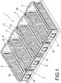
- Figure 1 shows an embodiment of the pan 1 showing the enveloping tubular profile 4 acting as reinforcing structure of the pan 1 and protects the edges of the moulds 2.
- This profile 4 is mounted on fastening parts 5 integrally joined to the walls of the ends of the moulds 2.
- the same figure 1 shows the corrugations 6 of the longer sidewalls 7 of the moulds 2 which have the function of facilitating the fast heat transmission during the baking process of the dough.
- these corrugations 6 define a plurality of vertical ribs 6a with respect to the base of the moulds 2 which have the function of facilitating the extraction of the bread once baked.
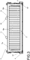
- Figure 2 shows a plan view of the pan 1 of figure 1 lacking the plate 3 acting as a cover and figure 3 a cross-section of said pan 1.
- Figure 2 shows the air inlet orifices 8 of the base of the pan 1, and the bar 9 wherein the supports 20 of the hooks 11 of the fastening device 12 of the plate 3 are mounted. The ends of this bar 9 are integrally joined to the enveloping tubular profile 4 which protects the edges of the moulds 2.
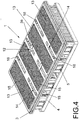
- Figure 4 shows a perspective view of the same pan 1 of figure 1 provided with the plate 3 comprising the recesses 13 which act as cover of the moulds 2.
- the plate 3 is provided with a plurality of grooves 14 which extend longitudinally between each two recesses 13. These grooves 14 facilitate the air circulation to favour the heat transmission during the baking and, furthermore, enable the installation of the hooks 11 of the fastening device 12.
- the same figure 4 shows the air inlet orifices 15 provided on the portions of the plate 3 which define the recesses 13.
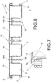
- Figure 6 shows a longitudinal section of the pan 1 provided with the plate 3 which has the recesses 13 which act as cover of the moulds 2.
- the recesses 13 penetrate inside the cavity of the moulds 2 defining an insert "e" in the upper edge of the walls.
- the same figure 6 shows the corrugations 16 of the surface of the recesses 13 and the section of the enveloping tubular profile 4.
- This profile 4 acts as a reinforcement and is mounted separated from the edges of the moulds 2 so that it defines a space 17 for the air circulation.
- the tubular profile 4 protrudes from the base 2a of the moulds 2 to protect said base 2a from the wear caused by contact with the transport chains of the industry.
- the thickness of the sheet that the moulds 2 is manufactured with may be lower than 1 mm, preferably of a thickness of 0.8 mm to facilitate maximum energy saving.
- the present invention proposes means of vertical stacking which include lugs 18 which extend vertically upward towards the reinforcing tubular profile 4 and are susceptible of insertion in recipient cavities associated to the reinforcing structure or profile of another pan similar to that claimed.
- each one of said lugs 18 is configured by a profile which defines at its lower end a recipient cavity 19 of the lug of another pan and at its upper end a protuberance 18a for the insertion of said lug 18.
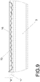
- figure 9 shows a detail of the longitudinal section of the plate 3 of figure 8 wherein the slightly convex profile of said recesses is observed 13, which, in this case, has been obtained by inlaying of the plate 3 and defining a convexity of a height "h" of 2.20 mm.
- the same figure 9 shows the corrugations 16 of the plate 3 which facilitate heat transmission during the baking, as well as the insert "e” to allow the adjustment with the upper edge of the walls of the moulds 2.
- Figure 7 shows a detail of the longitudinal section of the pan 1 wherein the insert "e” of a recess 13 is observed of the plate 3 acting as a cover in a mould 2 of the end of the pan 1.
- the recess 13 penetrates in the inner cavity of the mould 2 accurately adjusting to the upper edge 7a of the walls 7 to exactly delimit the growth space of the dough.
- the edge 7a of the walls 7 of the mould is lacking corrugations to enable the insertion of the recess 13 of the plate 3.
- FIG 5 is a cross-section of the pan 1 of figure 3 wherein said device 12 is observed in detail.
- the fastening device 12 comprises a pair of hooks 11 which are hingedly joined to one end of a vertical support 20 which is joined to a bar 9 integrally joined to the enveloping tubular profile 4.
- Each one of the hooks 11 automatically tilts towards the closed position thanks to a weight 21 which is associated to the body of the hook 11.
- On tilting to this closed position each one of the hooks 11 traverses a groove 14a of the plate 3 to catch a portion 3a of said plate 3 by a fastening member 11 a.
- the same figure 5 shows the upper rounded edge of the hooks 11 to facilitate the upper sliding of the plate 3 and the tilting of the hook 11.
- the fastening device 12 claimed has the advantage that it is very simple, effective and safe. Furthermore, it allows reducing the weight of the cover to approximately 4 kg which results in a lower energy consumption during baking. On the other hand, said fastening device 12 is very easy to apply industrially thanks to the automatic closure system.
- the pan 1 is light and resistant and guarantees the obtainment of a loaf with a regular section, since the recesses 13 effectively delimit the bread baking cavity.
- the embodiment of the pan 1 shown in figure 10 is differentiated from the aforementioned embodiment in the fact that the fastening device 12 is associated to a pair of structures 22 of the pan 1 which are interposed between two moulds 2, so that they hang joined to the walls of said moulds 2.
- Each one of said structures 22 includes a shaft 23 whereto is hingedly joined a fastening hook 11 of the plate 3 acting as a cover. The hooks 11 can tilt on the shafts 23 to each catch a lower portion 3b of the plate 3.
- the hooks 11 automatically tilt to the closed position thanks to a weight 21 which is configured by way of a counterweight and associated to the body of the hook 11.
- the hooks 11 remain concealed under the plate 3 in the closed position of the plate 3, which provides a more compact design which further facilitated the handling of the pan 1 in the production chain (see figures 12 and 13 ).
- the plate 3 acting as a cover includes a pair of lower portions 3b which extend from the underside of the plate 3 to be able to be gripped.
- Figure 11 shows a top perspective view of the plate 3 where said lower portions 3b can be observed.
- Figures 12 and 13 show the shafts 23 whereon the hooks 11 tilt, and the part 24 which acts as a stop to limit the movement of the hooks 11.
- the hooks 11 fasten the lower portions 3b remaining at the same time concealed under the plate 3.
- both the hooks 11 and the weights 21 can be actuated by a piston or equivalent member to automatically and continuously release the plate 3 without having to stop the production chain.
- figure 12 schematically represents, a piston 25 disposed to actuate from the lower part of the pan 1 the weights 21 and make the hooks 11 tilt in order to release the plate 3.
- Figure 13 represents an alternative manner of releasing the same hook 11 by an actuating member disposed to simultaneously press the edge of the hooks 11 and make the weights 21 tilt in order to release the plate 3.
- fastening hook 11 has been described in figures 1 to 9 hingedly joined to a shaft of the bar 9 through a vertical support 20, the same hook can be joined or hinged directly to a bar or part of the pan structure which is situated so that it allows actuation of the weight 21 by the lower part or base of the pan, as shown in figure 12 .
- This detail enables the automatic opening of the cover from the base making the hook tilt.
Landscapes
- Life Sciences & Earth Sciences (AREA)
- Engineering & Computer Science (AREA)
- Food Science & Technology (AREA)
- Baking, Grill, Roasting (AREA)
- Food-Manufacturing Devices (AREA)
- Table Devices Or Equipment (AREA)
- Bakery Products And Manufacturing Methods Therefor (AREA)
Claims (14)
- Schale (1) zum Backen eines Brotlaibs, die eine Mehrzahl von Backformen (2), eine Platte (3), die als eine Abdeckung der Schale (1) dient, und eine Einrichtung zum Verhindern des Hochhebens der Platte (3), während das Brot in den Formen (2) gebacken wird, aufweist, wobei die Einrichtung zum Verhindern des Hochhebens der Platte (3) eine Befestigungsvorrichtung (12) aufweist, die einer Struktur (9, 22) der Schale (1) zugeordnet ist, wobei
die Befestigungsvorrichtung (12) zumindest einen Haken (11) umfasst, der gelenkig mit einer Welle (23) der Struktur (9, 22) der Schale verbunden ist, dadurch gekennzeichnet, dass die Struktur zwischen zwei der Backformen (2) angeordnet ist, wobei der Haken (11) mit einem Gewicht (21) verbunden ist, das durch ein Gegengewicht konfiguriert ist, um zu bewirken, dass der Haken (11) sich automatisch neigt, um einen Abschnitt (3a, 3b) der Platte (3) zu befestigen, wobei das gleiche Gewicht (21) als ein Gegengewicht wirken kann, falls dasselbe betätigt wird, um zu bewirken, dass sich der Haken (11) in der entgegengesetzten Richtung neigt, um den Haken (11) von der Platte (3) zu lösen. - Schale (1) gemäß Anspruch 1, bei der die Platte (3) eine Mehrzahl von Ausnehmungen (13) aufweist, wobei jede der Ausnehmungen (13) durch eine Abdeckung von jeder der Formen (2) wirkt und jede der Ausnehmungen (13) einen Einsatz ("e") definiert, der konfiguriert ist, um in den inneren Hohlraum von jeder der Formen (2) in dem oberen Rand (7a) der Wände (7) der Formen (2) einzudringen.
- Schale (1) gemäß Anspruch 1, bei der die Platte (3), die als eine Abdeckung dient, einen Abschnitt (3b) aufweist, der sich von der Unterseite der Platte (3) nach unten erstreckt, wobei der Abschnitt (3b) zwischen zwei der Formen (2) angeordnet ist, so dass derselbe durch den Haken (11) gegriffen werden kann, während der Haken (11) unter der Platte (3) verborgen bleibt.
- Schale (1) gemäß Anspruch 1, wobei die Struktur (22) der Schale, mit der der Haken (11) verbunden ist, ein Stück (24) aufweist, das als ein Anschlag wirkt, um die Neigungsbewegung des Gewichts (21) und des Hakens (11) zu begrenzen.
- Schale (1) gemäß einem der Ansprüche 1 bis 4, bei der der Befestigungshaken (11) der Vorrichtung (12) einen oberen Rand mit einem gekrümmten Profil aufweist, um das obere Gleiten der Platte (3) auf den Formen (2) zu ermöglichen.
- Schale (1) gemäß Anspruch 2, bei der die Ausnehmungen (13) der Platte (3) jeweils einen Einsatz ("e") definieren, der konfiguriert ist, um den Innenhohlraum der Form (2) um einen Abstand gleich oder größer 5 mm zu durchdringen.
- Schale (1) gemäß einem der Ansprüche 1 bis 12, bei der die Ausnehmungen (13) jeweils eine Oberfläche mit Rillen (16) aufweisen, die entworfen ist, um die Öffnung der Formen (2) zu bedecken.
- Schale (1) gemäß einem der Anspruch 7, bei der die Oberfläche mit Rillen (16) ein im Wesentlichen konvexes Profil aufweist.
- Schale (1) gemäß einem der Ansprüche 7 bis 8, bei der die Oberfläche mit Rillen eine Mehrzahl von Öffnungen (15) aufweist, um das Eindringen von Luft zu ermöglichen.
- Schale (1) gemäß einem der vorhergehenden Ansprüche, die eine Verstärkungsstruktur aufweist, die ein röhrenförmiges Profil (4) umfasst, das an dem Umfang der Schale (1) angeordnet ist, wobei das röhrenförmige Profil (4) die Ränder der Formen (2) umhüllt und das röhrenförmige Profil (4) von den Rändern getrennt ist, so dass dasselbe einen Raum (17) für die Luftzirkulation definiert.
- Schale (1) gemäß Anspruch 10, bei der ferner das röhrenförmige Profil (4) befestigt ist, so dass dasselbe im Wesentlichen von der Basis (2a) der Formen (2) vorsteht.
- Schale (1) gemäß einem der Ansprüche 10 bis 11, die eine Einrichtung aufweist zum vertikalen Stapeln von zwei oder mehr Einheiten, wobei die Einrichtung eine Mehrzahl von Vorsprüngen (18) aufweist, die der Verstärkungsstruktur (4) der Schale (1) zugeordnet ist, wobei die Vorsprünge (18) in eine Mehrzahl von aufnehmenden Hohlräumen (19) eingefügt werden können, die der Verstärkungsstruktur einer weiteren Schale zugeordnet sind, wobei die Platte (3), die als eine Abdeckung der Schale (1) wirkt, mit einer Mehrzahl von Einschnitten (14) versehen ist, durch die die Vorsprünge (18) vorstehen, wenn die Ausnehmungen (13) der Platte (3) die Öffnungen der Formen (2) bedecken.
- Schale (1) gemäß Anspruch 2, bei der die Seitenwände (7) der Formen Rillen (6) aufweisen, wobei zumindest der obere Rand (7a) der Wände (7) der Rillen (6) ausgespart ist, um den Einsatz ("e") der Ausnehmungen (13) der Platte (3) zu ermöglichen.
- Schale (1) gemäß Anspruch 13, bei der die Rillen (6) der Seitenwände (7) eine Mehrzahl von Rippen (6a) definieren, die bezüglich der Basis (2a) der Schale (1) vertikal angeordnet sind.
Priority Applications (1)
| Application Number | Priority Date | Filing Date | Title |
|---|---|---|---|
| PL13821165T PL2916658T3 (pl) | 2012-10-31 | 2013-10-29 | Blacha do wypieku chleba |
Applications Claiming Priority (2)
| Application Number | Priority Date | Filing Date | Title |
|---|---|---|---|
| ES201231162U ES1078030Y (es) | 2012-10-31 | 2012-10-31 | Molde para elaborar pan |
| PCT/IB2013/059753 WO2014068481A1 (en) | 2012-10-31 | 2013-10-29 | Pan for baking bread |
Publications (2)
| Publication Number | Publication Date |
|---|---|
| EP2916658A1 EP2916658A1 (de) | 2015-09-16 |
| EP2916658B1 true EP2916658B1 (de) | 2017-07-26 |
Family
ID=47074479
Family Applications (1)
| Application Number | Title | Priority Date | Filing Date |
|---|---|---|---|
| EP13821165.1A Active EP2916658B1 (de) | 2012-10-31 | 2013-10-29 | Backform für brot |
Country Status (10)
| Country | Link |
|---|---|
| US (2) | US10219519B2 (de) |
| EP (1) | EP2916658B1 (de) |
| CN (1) | CN104822268B (de) |
| AU (1) | AU2013340396B2 (de) |
| BR (1) | BR112015009688B1 (de) |
| CA (1) | CA2889816C (de) |
| ES (1) | ES1078030Y (de) |
| MX (1) | MX357587B (de) |
| PL (1) | PL2916658T3 (de) |
| WO (1) | WO2014068481A1 (de) |
Families Citing this family (25)
| Publication number | Priority date | Publication date | Assignee | Title |
|---|---|---|---|---|
| FR3010865B1 (fr) | 2013-09-24 | 2016-07-29 | Mecatherm | Dispositif de plaque support de cuisson de produits de boulangerie, viennoiserie et patisserie |
| JP2016015889A (ja) * | 2014-07-04 | 2016-02-01 | 株式会社神戸屋 | 丸底パン型 |
| USD816387S1 (en) | 2017-03-03 | 2018-05-01 | Tristar Products, Inc. | Cooking apparatus |
| USD828710S1 (en) | 2017-03-03 | 2018-09-18 | Tristar Products, Inc. | Cooking apparatus |
| USD801104S1 (en) | 2017-03-03 | 2017-10-31 | Tristar Products, Inc. | Cooking apparatus |
| USD828075S1 (en) | 2017-03-03 | 2018-09-11 | Tristar Products, Inc. | Cooking apparatus |
| USD815879S1 (en) | 2017-03-03 | 2018-04-24 | Tristar Products, Inc. | Cooking apparatus |
| USD830099S1 (en) | 2017-03-03 | 2018-10-09 | Tristar Products, Inc. | Cooking apparatus |
| USD830112S1 (en) | 2016-10-07 | 2018-10-09 | Tristar Products, Inc. | Cooking apparatus |
| USD829487S1 (en) | 2016-10-07 | 2018-10-02 | Tristar Products, Inc. | Cooking apparatus |
| CN106342964A (zh) * | 2016-11-18 | 2017-01-25 | 淮北智淮科技有限公司 | 一种吐司面包模具及其加工工艺 |
| USD826621S1 (en) | 2017-03-03 | 2018-08-28 | Tristar Products, Inc. | Cooking apparatus |
| USD816406S1 (en) | 2017-03-03 | 2018-05-01 | Tristar Products, Inc. | Cooking apparatus |
| USD859060S1 (en) | 2017-03-03 | 2019-09-10 | Tristar Products, Inc. | Cooking pan |
| USD815882S1 (en) | 2017-03-03 | 2018-04-24 | Tristar Products, Inc. | Cooking apparatus |
| USD816404S1 (en) | 2017-03-03 | 2018-05-01 | Tristar Products, Inc. | Cooking apparatus |
| USD827374S1 (en) | 2017-03-03 | 2018-09-04 | Tristar Products, Inc. | Cooking apparatus |
| USD860725S1 (en) | 2017-03-03 | 2019-09-24 | Tristar Products, Inc. | Cooking apparatus |
| USD815881S1 (en) | 2017-03-03 | 2018-04-24 | Tristar Products, Inc. | Cooking apparatus |
| CN107094819A (zh) * | 2017-05-17 | 2017-08-29 | 昌顺烘焙科技(上海)股份有限公司 | 多连面包烤盘 |
| CN107150211B (zh) * | 2017-07-11 | 2023-12-08 | 河南赫斯特威自动化设备有限公司 | 一种多连装面包烤盒及其加工工艺 |
| NL2032945B1 (en) * | 2022-09-02 | 2024-03-21 | Kaak Groep B V | Method and assembly for preparing food products in a treatment unit |
| WO2024055085A1 (en) | 2022-09-16 | 2024-03-21 | Cainco Equipamentos Para Panificação Ltda. | Baking pan assembly |
| EP4702843A1 (de) | 2024-08-26 | 2026-03-04 | Kaak Groep B.V. | Träger, anordnung und verfahren zur herstellung von teigprodukten in einem ofen |
| EP4740737A1 (de) * | 2024-11-11 | 2026-05-13 | Fabula S.r.l. | Ofenvorrichtung zur herstellung von panettone mit flacher oberseite während des backvorganges |
Family Cites Families (20)
| Publication number | Priority date | Publication date | Assignee | Title |
|---|---|---|---|---|
| US581232A (en) * | 1897-04-20 | The nor | ||
| US1050449A (en) * | 1912-01-17 | 1913-01-14 | William J Gillespie | Pan for baking bread. |
| GB386377A (en) | 1931-10-12 | 1933-01-19 | Herbert Owen | Improvements relating to baking tins |
| US2023812A (en) * | 1934-07-11 | 1935-12-10 | Katzinger Edward Co | Baking pan set |
| US2071845A (en) * | 1935-12-19 | 1937-02-23 | Kowalski Waclaw | Bread form |
| US2347694A (en) * | 1942-01-31 | 1944-05-02 | Chicago Metallic Mfg Company | Multiple baking pan |
| US2654502A (en) * | 1952-09-12 | 1953-10-06 | Ekco Products Company | Cover for bake pans |
| FR1166787A (fr) * | 1956-03-20 | 1958-11-14 | Sidam Srl | Forme multiple pour la cuisson de miches de pain ou de produits similaires |
| US2903151A (en) * | 1957-11-25 | 1959-09-08 | Alcaro Anthony | Means for attaching baking pan covers to baking pans |
| US3476262A (en) * | 1967-11-15 | 1969-11-04 | Bucks County Enterprises Inc | Stacking arrangement for pie trays |
| US3862339A (en) * | 1972-12-11 | 1975-01-21 | Gen Foods Corp | Process fsr making rectilinear bread loaves |
| CA1243631A (en) * | 1985-12-19 | 1988-10-25 | Sajjad Ebrahim | Cover for baked goods |
| US5048707A (en) * | 1989-11-13 | 1991-09-17 | The United States Of America As Represented By The Secretary Of The Army | Accordion bread pan |
| CA2129272A1 (en) | 1994-08-01 | 1996-02-02 | Line Groulx | Edible bun having a compartmented central recess and a baking mold for producing same |
| US6003705A (en) * | 1998-05-19 | 1999-12-21 | Magnum Mud Equipment Company | Portable bulk storage container having and easy opening lid |
| US6973872B2 (en) * | 2002-11-15 | 2005-12-13 | Fletcher Morgan | Individual dome molds and baking assembly |
| AU2007200951B2 (en) | 2006-03-30 | 2012-05-17 | Moffat Pty Limited | A lidding system |
| EP2179656A1 (de) * | 2008-10-24 | 2010-04-28 | Cremona Inoxidable S.r.l. | System zum Stapeln und Entstapeln von Formeinheiten |
| US9936707B2 (en) * | 2009-09-28 | 2018-04-10 | American Pan Company | Segmented industrial baking pan |
| US20120003363A1 (en) | 2010-07-03 | 2012-01-05 | Beloff Arthur L | Edible bread cup and method of production |
-
2012
- 2012-10-31 ES ES201231162U patent/ES1078030Y/es not_active Expired - Fee Related
-
2013
- 2013-10-29 EP EP13821165.1A patent/EP2916658B1/de active Active
- 2013-10-29 CA CA2889816A patent/CA2889816C/en active Active
- 2013-10-29 WO PCT/IB2013/059753 patent/WO2014068481A1/en not_active Ceased
- 2013-10-29 AU AU2013340396A patent/AU2013340396B2/en active Active
- 2013-10-29 CN CN201380056382.3A patent/CN104822268B/zh active Active
- 2013-10-29 PL PL13821165T patent/PL2916658T3/pl unknown
- 2013-10-29 BR BR112015009688-3A patent/BR112015009688B1/pt active IP Right Grant
- 2013-10-29 US US14/438,741 patent/US10219519B2/en active Active
- 2013-10-29 MX MX2015005499A patent/MX357587B/es active IP Right Grant
-
2019
- 2019-01-18 US US16/252,455 patent/US11252967B2/en active Active
Non-Patent Citations (1)
| Title |
|---|
| None * |
Also Published As
| Publication number | Publication date |
|---|---|
| US20150250189A1 (en) | 2015-09-10 |
| EP2916658A1 (de) | 2015-09-16 |
| ES1078030Y (es) | 2013-02-11 |
| US10219519B2 (en) | 2019-03-05 |
| AU2013340396B2 (en) | 2017-08-31 |
| BR112015009688A2 (pt) | 2017-07-04 |
| US11252967B2 (en) | 2022-02-22 |
| US20190150456A1 (en) | 2019-05-23 |
| CN104822268A (zh) | 2015-08-05 |
| BR112015009688B1 (pt) | 2020-08-11 |
| CA2889816C (en) | 2021-01-12 |
| CA2889816A1 (en) | 2014-05-08 |
| HK1209974A1 (en) | 2016-04-15 |
| CN104822268B (zh) | 2018-01-09 |
| BR112015009688A8 (pt) | 2019-09-17 |
| ES1078030U (es) | 2012-11-15 |
| MX2015005499A (es) | 2015-11-30 |
| PL2916658T3 (pl) | 2018-01-31 |
| AU2013340396A1 (en) | 2015-05-14 |
| WO2014068481A1 (en) | 2014-05-08 |
| MX357587B (es) | 2018-07-16 |
Similar Documents
| Publication | Publication Date | Title |
|---|---|---|
| US11252967B2 (en) | Pan for baking bread | |
| EP1864575B1 (de) | Silikonbackblech | |
| CN104936455B (zh) | 用于烘烤圆面包的设备和方法 | |
| US20090250473A1 (en) | Convertible insulated cooking utensil | |
| HK1201705A1 (en) | Multi-purpose cooking vessel and method of manufacturing the same | |
| AU673271B2 (en) | Bread baking | |
| EP2592976B1 (de) | Dampfgarer | |
| ES2760254T3 (es) | Dispositivo de placa de soporte para productos de panadería, pastelería o repostería | |
| HK1209974B (en) | Pan for baking bread | |
| KR101162025B1 (ko) | 조리용기 성형용 금형 | |
| JP3181170U (ja) | 料理用鍋 | |
| ES2644756T3 (es) | Molde para elaborar pan | |
| KR101332565B1 (ko) | 후라이팬 및 그 제조방법 | |
| CN115151171A (zh) | 带有易于抓握的可拆卸容器的模具及其支撑件 | |
| JP4324546B2 (ja) | パンの焼き色を抑える焼成用治具 | |
| AU2007200951B2 (en) | A lidding system | |
| ES1068784U (es) | Bandeja para la preparacion de barras de pan. | |
| CN219126055U (zh) | 把手可脱卸的烤箱双面烤盘 | |
| US20070248722A1 (en) | Lidding system | |
| CA2583162C (en) | A lidding system | |
| ES1068783U (es) | Bandeja para la preparacion de barras de pan. | |
| CN209883864U (zh) | 一种均匀受热易脱模烤盘 | |
| US20130025471A1 (en) | Pie crust protector pan | |
| JP3143721U (ja) | 電子レンジ調理用容器 | |
| CZ21541U1 (cs) | Forma na pečení bábovky s různě velkými dílky |
Legal Events
| Date | Code | Title | Description |
|---|---|---|---|
| PUAI | Public reference made under article 153(3) epc to a published international application that has entered the european phase |
Free format text: ORIGINAL CODE: 0009012 |
|
| 17P | Request for examination filed |
Effective date: 20150527 |
|
| AK | Designated contracting states |
Kind code of ref document: A1 Designated state(s): AL AT BE BG CH CY CZ DE DK EE ES FI FR GB GR HR HU IE IS IT LI LT LU LV MC MK MT NL NO PL PT RO RS SE SI SK SM TR |
|
| AX | Request for extension of the european patent |
Extension state: BA ME |
|
| DAX | Request for extension of the european patent (deleted) | ||
| REG | Reference to a national code |
Ref country code: HK Ref legal event code: DE Ref document number: 1209974 Country of ref document: HK |
|
| GRAP | Despatch of communication of intention to grant a patent |
Free format text: ORIGINAL CODE: EPIDOSNIGR1 |
|
| STAA | Information on the status of an ep patent application or granted ep patent |
Free format text: STATUS: GRANT OF PATENT IS INTENDED |
|
| INTG | Intention to grant announced |
Effective date: 20170214 |
|
| GRAS | Grant fee paid |
Free format text: ORIGINAL CODE: EPIDOSNIGR3 |
|
| GRAA | (expected) grant |
Free format text: ORIGINAL CODE: 0009210 |
|
| STAA | Information on the status of an ep patent application or granted ep patent |
Free format text: STATUS: THE PATENT HAS BEEN GRANTED |
|
| AK | Designated contracting states |
Kind code of ref document: B1 Designated state(s): AL AT BE BG CH CY CZ DE DK EE ES FI FR GB GR HR HU IE IS IT LI LT LU LV MC MK MT NL NO PL PT RO RS SE SI SK SM TR |
|
| REG | Reference to a national code |
Ref country code: GB Ref legal event code: FG4D |
|
| REG | Reference to a national code |
Ref country code: CH Ref legal event code: EP |
|
| REG | Reference to a national code |
Ref country code: AT Ref legal event code: REF Ref document number: 911631 Country of ref document: AT Kind code of ref document: T Effective date: 20170815 |
|
| REG | Reference to a national code |
Ref country code: IE Ref legal event code: FG4D |
|
| REG | Reference to a national code |
Ref country code: DE Ref legal event code: R096 Ref document number: 602013024171 Country of ref document: DE |
|
| REG | Reference to a national code |
Ref country code: FR Ref legal event code: PLFP Year of fee payment: 5 |
|
| REG | Reference to a national code |
Ref country code: RO Ref legal event code: EPE |
|
| REG | Reference to a national code |
Ref country code: NL Ref legal event code: FP |
|
| REG | Reference to a national code |
Ref country code: ES Ref legal event code: FG2A Ref document number: 2644756 Country of ref document: ES Kind code of ref document: T3 Effective date: 20171130 |
|
| REG | Reference to a national code |
Ref country code: LT Ref legal event code: MG4D |
|
| REG | Reference to a national code |
Ref country code: AT Ref legal event code: MK05 Ref document number: 911631 Country of ref document: AT Kind code of ref document: T Effective date: 20170726 |
|
| PG25 | Lapsed in a contracting state [announced via postgrant information from national office to epo] |
Ref country code: LT Free format text: LAPSE BECAUSE OF FAILURE TO SUBMIT A TRANSLATION OF THE DESCRIPTION OR TO PAY THE FEE WITHIN THE PRESCRIBED TIME-LIMIT Effective date: 20170726 Ref country code: SE Free format text: LAPSE BECAUSE OF FAILURE TO SUBMIT A TRANSLATION OF THE DESCRIPTION OR TO PAY THE FEE WITHIN THE PRESCRIBED TIME-LIMIT Effective date: 20170726 Ref country code: HR Free format text: LAPSE BECAUSE OF FAILURE TO SUBMIT A TRANSLATION OF THE DESCRIPTION OR TO PAY THE FEE WITHIN THE PRESCRIBED TIME-LIMIT Effective date: 20170726 Ref country code: FI Free format text: LAPSE BECAUSE OF FAILURE TO SUBMIT A TRANSLATION OF THE DESCRIPTION OR TO PAY THE FEE WITHIN THE PRESCRIBED TIME-LIMIT Effective date: 20170726 Ref country code: NO Free format text: LAPSE BECAUSE OF FAILURE TO SUBMIT A TRANSLATION OF THE DESCRIPTION OR TO PAY THE FEE WITHIN THE PRESCRIBED TIME-LIMIT Effective date: 20171026 Ref country code: AT Free format text: LAPSE BECAUSE OF FAILURE TO SUBMIT A TRANSLATION OF THE DESCRIPTION OR TO PAY THE FEE WITHIN THE PRESCRIBED TIME-LIMIT Effective date: 20170726 |
|
| PG25 | Lapsed in a contracting state [announced via postgrant information from national office to epo] |
Ref country code: LV Free format text: LAPSE BECAUSE OF FAILURE TO SUBMIT A TRANSLATION OF THE DESCRIPTION OR TO PAY THE FEE WITHIN THE PRESCRIBED TIME-LIMIT Effective date: 20170726 Ref country code: IS Free format text: LAPSE BECAUSE OF FAILURE TO SUBMIT A TRANSLATION OF THE DESCRIPTION OR TO PAY THE FEE WITHIN THE PRESCRIBED TIME-LIMIT Effective date: 20171126 Ref country code: RS Free format text: LAPSE BECAUSE OF FAILURE TO SUBMIT A TRANSLATION OF THE DESCRIPTION OR TO PAY THE FEE WITHIN THE PRESCRIBED TIME-LIMIT Effective date: 20170726 Ref country code: BG Free format text: LAPSE BECAUSE OF FAILURE TO SUBMIT A TRANSLATION OF THE DESCRIPTION OR TO PAY THE FEE WITHIN THE PRESCRIBED TIME-LIMIT Effective date: 20171026 Ref country code: GR Free format text: LAPSE BECAUSE OF FAILURE TO SUBMIT A TRANSLATION OF THE DESCRIPTION OR TO PAY THE FEE WITHIN THE PRESCRIBED TIME-LIMIT Effective date: 20171027 |
|
| REG | Reference to a national code |
Ref country code: HK Ref legal event code: GR Ref document number: 1209974 Country of ref document: HK |
|
| PG25 | Lapsed in a contracting state [announced via postgrant information from national office to epo] |
Ref country code: DK Free format text: LAPSE BECAUSE OF FAILURE TO SUBMIT A TRANSLATION OF THE DESCRIPTION OR TO PAY THE FEE WITHIN THE PRESCRIBED TIME-LIMIT Effective date: 20170726 |
|
| REG | Reference to a national code |
Ref country code: DE Ref legal event code: R097 Ref document number: 602013024171 Country of ref document: DE |
|
| PG25 | Lapsed in a contracting state [announced via postgrant information from national office to epo] |
Ref country code: SK Free format text: LAPSE BECAUSE OF FAILURE TO SUBMIT A TRANSLATION OF THE DESCRIPTION OR TO PAY THE FEE WITHIN THE PRESCRIBED TIME-LIMIT Effective date: 20170726 Ref country code: SM Free format text: LAPSE BECAUSE OF FAILURE TO SUBMIT A TRANSLATION OF THE DESCRIPTION OR TO PAY THE FEE WITHIN THE PRESCRIBED TIME-LIMIT Effective date: 20170726 Ref country code: EE Free format text: LAPSE BECAUSE OF FAILURE TO SUBMIT A TRANSLATION OF THE DESCRIPTION OR TO PAY THE FEE WITHIN THE PRESCRIBED TIME-LIMIT Effective date: 20170726 Ref country code: MC Free format text: LAPSE BECAUSE OF FAILURE TO SUBMIT A TRANSLATION OF THE DESCRIPTION OR TO PAY THE FEE WITHIN THE PRESCRIBED TIME-LIMIT Effective date: 20170726 |
|
| REG | Reference to a national code |
Ref country code: CH Ref legal event code: PL |
|
| PLBE | No opposition filed within time limit |
Free format text: ORIGINAL CODE: 0009261 |
|
| STAA | Information on the status of an ep patent application or granted ep patent |
Free format text: STATUS: NO OPPOSITION FILED WITHIN TIME LIMIT |
|
| 26N | No opposition filed |
Effective date: 20180430 |
|
| REG | Reference to a national code |
Ref country code: IE Ref legal event code: MM4A |
|
| PG25 | Lapsed in a contracting state [announced via postgrant information from national office to epo] |
Ref country code: LI Free format text: LAPSE BECAUSE OF NON-PAYMENT OF DUE FEES Effective date: 20171031 Ref country code: LU Free format text: LAPSE BECAUSE OF NON-PAYMENT OF DUE FEES Effective date: 20171029 Ref country code: CH Free format text: LAPSE BECAUSE OF NON-PAYMENT OF DUE FEES Effective date: 20171031 |
|
| REG | Reference to a national code |
Ref country code: BE Ref legal event code: MM Effective date: 20171031 |
|
| PG25 | Lapsed in a contracting state [announced via postgrant information from national office to epo] |
Ref country code: SI Free format text: LAPSE BECAUSE OF FAILURE TO SUBMIT A TRANSLATION OF THE DESCRIPTION OR TO PAY THE FEE WITHIN THE PRESCRIBED TIME-LIMIT Effective date: 20170726 Ref country code: BE Free format text: LAPSE BECAUSE OF NON-PAYMENT OF DUE FEES Effective date: 20171031 |
|
| REG | Reference to a national code |
Ref country code: FR Ref legal event code: PLFP Year of fee payment: 6 |
|
| PG25 | Lapsed in a contracting state [announced via postgrant information from national office to epo] |
Ref country code: MT Free format text: LAPSE BECAUSE OF NON-PAYMENT OF DUE FEES Effective date: 20171029 |
|
| PG25 | Lapsed in a contracting state [announced via postgrant information from national office to epo] |
Ref country code: IE Free format text: LAPSE BECAUSE OF NON-PAYMENT OF DUE FEES Effective date: 20171029 |
|
| PG25 | Lapsed in a contracting state [announced via postgrant information from national office to epo] |
Ref country code: HU Free format text: LAPSE BECAUSE OF FAILURE TO SUBMIT A TRANSLATION OF THE DESCRIPTION OR TO PAY THE FEE WITHIN THE PRESCRIBED TIME-LIMIT; INVALID AB INITIO Effective date: 20131029 |
|
| PG25 | Lapsed in a contracting state [announced via postgrant information from national office to epo] |
Ref country code: CY Free format text: LAPSE BECAUSE OF FAILURE TO SUBMIT A TRANSLATION OF THE DESCRIPTION OR TO PAY THE FEE WITHIN THE PRESCRIBED TIME-LIMIT Effective date: 20170726 |
|
| PG25 | Lapsed in a contracting state [announced via postgrant information from national office to epo] |
Ref country code: MK Free format text: LAPSE BECAUSE OF FAILURE TO SUBMIT A TRANSLATION OF THE DESCRIPTION OR TO PAY THE FEE WITHIN THE PRESCRIBED TIME-LIMIT Effective date: 20170726 |
|
| PG25 | Lapsed in a contracting state [announced via postgrant information from national office to epo] |
Ref country code: PT Free format text: LAPSE BECAUSE OF FAILURE TO SUBMIT A TRANSLATION OF THE DESCRIPTION OR TO PAY THE FEE WITHIN THE PRESCRIBED TIME-LIMIT Effective date: 20170726 |
|
| PG25 | Lapsed in a contracting state [announced via postgrant information from national office to epo] |
Ref country code: AL Free format text: LAPSE BECAUSE OF FAILURE TO SUBMIT A TRANSLATION OF THE DESCRIPTION OR TO PAY THE FEE WITHIN THE PRESCRIBED TIME-LIMIT Effective date: 20170726 |
|
| REG | Reference to a national code |
Ref country code: DE Ref legal event code: R082 Ref document number: 602013024171 Country of ref document: DE Representative=s name: ISARPATENT - PATENT- UND RECHTSANWAELTE BARTH , DE Ref country code: DE Ref legal event code: R081 Ref document number: 602013024171 Country of ref document: DE Owner name: COATRESA S.L.U., ES Free format text: FORMER OWNERS: FERREIRA SANTOS, RAQUEL SOFIA, MAIA, PT; MAGAR INVEST S.L., BARBERA DEL VALLES, ES Ref country code: DE Ref legal event code: R081 Ref document number: 602013024171 Country of ref document: DE Owner name: FERREIRA SANTOS, RAQUEL SOFIA, PT Free format text: FORMER OWNERS: FERREIRA SANTOS, RAQUEL SOFIA, MAIA, PT; MAGAR INVEST S.L., BARBERA DEL VALLES, ES |
|
| REG | Reference to a national code |
Ref country code: ES Ref legal event code: PC2A Owner name: COATRESA, S.L.U. Effective date: 20201214 |
|
| REG | Reference to a national code |
Ref country code: GB Ref legal event code: 732E Free format text: REGISTERED BETWEEN 20210107 AND 20210113 |
|
| REG | Reference to a national code |
Ref country code: NL Ref legal event code: PD Owner name: COATRESA S.L.U.; ES Free format text: DETAILS ASSIGNMENT: CHANGE OF OWNER(S), ASSIGNMENT; FORMER OWNER NAME: MAGAR INVEST S.L. Effective date: 20211019 |
|
| PGFP | Annual fee paid to national office [announced via postgrant information from national office to epo] |
Ref country code: NL Payment date: 20251026 Year of fee payment: 13 |
|
| PGFP | Annual fee paid to national office [announced via postgrant information from national office to epo] |
Ref country code: DE Payment date: 20251029 Year of fee payment: 13 |
|
| PGFP | Annual fee paid to national office [announced via postgrant information from national office to epo] |
Ref country code: GB Payment date: 20251027 Year of fee payment: 13 |
|
| PGFP | Annual fee paid to national office [announced via postgrant information from national office to epo] |
Ref country code: IT Payment date: 20251021 Year of fee payment: 13 |
|
| PGFP | Annual fee paid to national office [announced via postgrant information from national office to epo] |
Ref country code: FR Payment date: 20251027 Year of fee payment: 13 |
|
| PGFP | Annual fee paid to national office [announced via postgrant information from national office to epo] |
Ref country code: TR Payment date: 20251007 Year of fee payment: 13 |
|
| PGFP | Annual fee paid to national office [announced via postgrant information from national office to epo] |
Ref country code: CZ Payment date: 20251006 Year of fee payment: 13 |
|
| PGFP | Annual fee paid to national office [announced via postgrant information from national office to epo] |
Ref country code: PL Payment date: 20251007 Year of fee payment: 13 |
|
| PGFP | Annual fee paid to national office [announced via postgrant information from national office to epo] |
Ref country code: RO Payment date: 20251006 Year of fee payment: 13 |
|
| PGFP | Annual fee paid to national office [announced via postgrant information from national office to epo] |
Ref country code: ES Payment date: 20251103 Year of fee payment: 13 |