EP2915944B1 - Slide guide frame section for screen devices - Google Patents
Slide guide frame section for screen devices Download PDFInfo
- Publication number
- EP2915944B1 EP2915944B1 EP13852260.2A EP13852260A EP2915944B1 EP 2915944 B1 EP2915944 B1 EP 2915944B1 EP 13852260 A EP13852260 A EP 13852260A EP 2915944 B1 EP2915944 B1 EP 2915944B1
- Authority
- EP
- European Patent Office
- Prior art keywords
- frame portion
- slide guide
- screen
- guide frame
- mounting frame
- Prior art date
- Legal status (The legal status is an assumption and is not a legal conclusion. Google has not performed a legal analysis and makes no representation as to the accuracy of the status listed.)
- Active
Links
Images


Classifications
-
- E—FIXED CONSTRUCTIONS
- E06—DOORS, WINDOWS, SHUTTERS, OR ROLLER BLINDS IN GENERAL; LADDERS
- E06B—FIXED OR MOVABLE CLOSURES FOR OPENINGS IN BUILDINGS, VEHICLES, FENCES OR LIKE ENCLOSURES IN GENERAL, e.g. DOORS, WINDOWS, BLINDS, GATES
- E06B9/00—Screening or protective devices for wall or similar openings, with or without operating or securing mechanisms; Closures of similar construction
- E06B9/52—Devices affording protection against insects, e.g. fly screens; Mesh windows for other purposes
- E06B9/54—Roller fly screens
-
- E—FIXED CONSTRUCTIONS
- E05—LOCKS; KEYS; WINDOW OR DOOR FITTINGS; SAFES
- E05D—HINGES OR SUSPENSION DEVICES FOR DOORS, WINDOWS OR WINGS
- E05D15/00—Suspension arrangements for wings
- E05D15/06—Suspension arrangements for wings for wings sliding horizontally more or less in their own plane
- E05D15/0621—Details, e.g. suspension or supporting guides
-
- E—FIXED CONSTRUCTIONS
- E06—DOORS, WINDOWS, SHUTTERS, OR ROLLER BLINDS IN GENERAL; LADDERS
- E06B—FIXED OR MOVABLE CLOSURES FOR OPENINGS IN BUILDINGS, VEHICLES, FENCES OR LIKE ENCLOSURES IN GENERAL, e.g. DOORS, WINDOWS, BLINDS, GATES
- E06B9/00—Screening or protective devices for wall or similar openings, with or without operating or securing mechanisms; Closures of similar construction
- E06B9/52—Devices affording protection against insects, e.g. fly screens; Mesh windows for other purposes
- E06B9/54—Roller fly screens
- E06B2009/543—Horizontally moving screens
Definitions
- the present invention relates to a slide guide frame portion disposed in a versatile screen device which can be used as a curtain, a blind, a screen door, and a partition wall.
- the present applicant proposes a screen device which performs smooth and stable opening/closing while releasing restrictions on installation when the screen device is used as a light blocking and light adjustment device such as the curtain and the blind, the screen door, and the partition wall ( JP2000145314 ).
- a screen is attached to be freely developed between a pair of screen mounting frame portions which are disposed to face each other, and at least one of the screen mounting frame portions can slide.
- a pair of slide guide frame portions are disposed in the vicinity of both ends portions of the screen not on a side where the screen is attached to the screen mounting frame portion.
- These two slide guide frame portions have flexibility, at least one end serves as a free end and capable of being stored in and drawn out of the slidable screen mounting frame portion.
- a portion of the slide guide frame portion drawn out of the screen mounting frame portion has linearity as the slidable screen mounting frame portion slides.
- the slide guide frame portion is formed by a plurality of rigid units in which adjacent two units are connected to each other.
- the rigid unit includes a pair of side wall portions disposed to face each other and a bridge portion linking both side wall portions.
- a protrusion protruding to the outside is disposed in one end portion in a length direction, and a through hole into which the protrusion can be inserted is formed in the other end portion.
- a small protrusion protrudes toward the outside is disposed which is adjacent to the protrusion and positioned on a side opposite to the through hole, and a long hole is formed which is adjacent to the through hole and formed in a substantially crescent shape on a side near the protrusion.
- Patent document EP 2915944 A1 describes a known slide guide frame portion while document EP 2 487 316 A1 shows a slide guide frame portion according to the preamble of claim 1.
- the screen device in which the slide guide frame portion is disposed as described above releases the restriction on installation and realizes the smooth and stable opening/closing, so that the screen device can be used in general purpose.
- the slidable screen mounting frame portion stores two slide guide frame portions therein, in order to reduce the width of the slidable screen mounting frame portion, the width of the slide guide frame portion is necessarily reduced.
- the slide guide frame portion formed of the present rigid units is degraded in strength for the connection between the rigid units.
- the dimension of the rigid unit in a height direction is necessarily reduced in order to realize the reduction of the width of the slide guide frame portion, but a long hole having the substantially crescent shape is formed in the side wall portion of the rigid unit, so that the strength of the side wall portion is insufficient.
- the long hole is necessarily made short for securing the strength of the side wall portion, but when the length of the long hole is made short, the size of the small protrusion becomes smaller, and thus it is not possible to secure a sufficient strength of the small protrusion.
- the invention has been made in view of the above circumstances, and an object thereof is to provide a slide guide frame portion of a screen device which can reduce the width of the slidable screen mounting frame portion while securing a sufficient strength for the connection between the rigid units.
- a slide guide frame portion of a screen device of the invention includes a pair of hollow screen mounting frame portions configured to be disposed to face each other in which at least one of the portions is capable of sliding, a screen configured to be attached between these screen mounting frame portions to be freely developed, and a slide guide frame portion configured to be disposed in the vicinity of either end portion of the screen not on a side where the screen is attached to the screen mounting frame portion.
- Each slide guide frame portion has flexibility, at least one end serves as a free end and is capable of being stored in and drawn out of the slidable screen mounting frame portion, and when the screen is drawn out of the screen mounting frame portion as the slidable screen mounting frame portion slides, a drawn-out portion of the slide guide frame portion has linearity.
- any one or both of the two slide guide frame portions are formed by a plurality of rigid units, each of which includes a pair of side wall portions disposed to face each other and a bridge portion linking both side wall portions from the substantially center portion to one end portion, in which adjacent two rigid units are rotatably connected to each other.
- a depressed portion which is depressed in a width direction of the rigid unit is formed in an approximately half portion from the substantially center portion to the one end portion
- a through hole which is made in the width direction of the rigid unit is formed in the approximately half portion from the substantially center portion to the other end portion, and a protrusion is provided adjacent to the through hole inside the substantially center portion.
- a shaft protruding toward the outside is provided in the substantially center portion, and a notch portion which is cut in a height direction of the rigid unit is formed from the substantially center portion of the depressed portion to the one end portion of the side wall portion.
- the adjacent two rigid units are connected such that the shaft of one rigid unit is inserted into the through hole of the other rigid unit from the inside, and the one rigid unit is freely rotated with respect to the other rigid unit within a range in which the protrusion abuts on one end and the other end of the notch portion.
- a chamfer portion inclining toward the inside in the width direction of the rigid unit is preferably formed on a side near the one end portion of the side wall portion.
- one of the two screen mounting frame portions is fixed, a roller pipe having a built-in coil spring is rotatably stored inside the fixed screen mounting frame portion, one end of the screen is attached to the roller pipe, the roller pipe is rotated by an elastic force generated in the coil spring, and the screen is preferably wound around the outer peripheral of the roller pipe.
- a reduced width of a slidable screen mounting frame portion can be realized while securing a connection strength enough for a rigid unit.
- Fig. 1 is a partially-broken front view illustrating an embodiment of a slide guide frame portion of a screen device of the invention, and the screen device which includes the slide guide frame portion.
- a screen device 1 includes a net 2a as a screen 2 which is opened or closed in a horizontal direction.
- the screen 2 is made of fabrics such as woven fabrics and knitted fabrics, and appropriately selected from those having a light blocking property or those used as insect screens according to necessary characteristics.
- the net 2a applied as the insect screen is employed.
- the shape of the screen 2 including the net 2a is not particularly limited, and can be pleated as needed.
- a hollow screen mounting frame portion 3 is disposed on the right side of the screen device 1.
- the screen mounting frame portion 3, for example, is fixed to a right frame which is extended in the longitudinal direction of a rectangular opening in a building.
- a roller pipe 4 is built in and contained therein.
- One end of the screen 2 is attached to the roller pipe 4.
- the roller pipe 4 includes a hollow main body 4a having a substantially cylindrical shape and a bearing 5 connected to the lower end of the main body 4a.
- a rotation shaft 6 is provided inside the main body 4a.
- the rotation shaft 6 is extended on the way to the roller pipe 4 in a height direction from the bearing 5.
- a coil spring 7 is built in the main body 4a, and the coil spring 7 is provided about the rotation shaft 6.
- the screen 2 of which the one end is attached to the roller pipe 4 is wound around the outer peripheral of the main body 4a.
- the main body 4a of the roller pipe 4 is rotated in a direction opposite to the above direction, and the coil spring 7 is twisted while accumulating the elastic force.
- the other end of the screen 2 is attached to a screen mounting frame portion 8 which can slide with respect to the fixed screen mounting frame portion 3 in the horizontal direction to open and close the screen 2.
- the screen mounting frame portion 8 includes a hollow main body 8a which is formed in a rectangular cylindrical shape having a rectangular cross portion, and the main body 8a is extended in the longitudinal direction of the screen device 1.
- the slidable screen mounting frame portion 8 for example, slides in the horizontal direction between the screen mounting frame portion 3 and a door stop frame 9 which is attached to the left frame which extends in the longitudinal direction of the opening of the building.
- the screen 2 is configured to be opened or closed by such a sliding of the screen mounting frame portion 8.
- a lower rail 10 is provided in a floor surface or the like in order to realize a smooth sliding of the screen mounting frame portion 8 and an upper rail 11 is provided in the upper frame which is extended in the horizontal direction of the opening of the building.
- the lower rail 10, for example, may be formed in an elongate rod shape.
- the upper rail 11, for example, may be formed as a frame having a U shape in cross-portional view. In this case, the upper rail 11 can cover and hide the upper end portions of the screen mounting frame portions 3 and 8 and the screen 2 from both front and back sides of the screen device 1, and contributes to an improvement in visual quality of the screen device 1.
- a handle may be provided in the front surface and even in the back surface as needed, so that the operator can easily open/close the screen.
- an upper slide guide frame portion 12 is provided in the vicinity of the upper end of the screen 2
- a lower slide guide frame portion 13 is provided in the vicinity of the lower end of the screen 2.
- the upper slide guide frame portion 12 and the lower slide guide frame portion 13 both serve to dispose the slidable screen mounting frame portion 8 in parallel to the screen mounting frame portion 3, and stably keep such a parallel positional relation even when the screen mounting frame portion 8 slides.
- the opening/closing of the screen 2 is securely performed by the upper slide guide frame portion 12 and the lower slide guide frame portion 13.
- the present slide guide frame portion is employed to the lower slide guide frame portion 13, and a new slide guide frame portion is employed to the upper slide guide frame portion 12.
- the lower slide guide frame portion 13 is formed by a plurality of first rigid units 14 as the present rigid units in which adjacent two rigid units are rotatably connected.
- the first rigid unit 14 includes a pair of side wall portions 15 which are disposed to face each other, and a bridge portion (not illustrated) which links both side wall portions 15 at a position near the upper end portion of the side wall portion 15 and in a left end portion from the substantially center portion.
- a protrusion 16 which protrudes to the side is disposed in the left end portion, and a through hole 17 where the protrusion 16 is inserted into and passes through in a width direction of the first rigid unit 14 is formed in the right end portion.
- the plurality of first rigid units 14 is connected by inserting the protrusions 16 of the adjacent two units into the through holes 17 from the back surface of the side wall portion 15, and forms the lower slide guide frame portion 13. In this way, since the first rigid units 14 are connected by inserting the protrusions 16 into the through holes 17, the first rigid units 14 are configured such that the adjacent two units are rotatably connected to each other. Since the first rigid units 14 are rotatably provided, the lower slide guide frame portion 13 is realized to have flexibility.
- a small protrusion 18 which protrudes to the outside from the side wall portion 15 is disposed on the left side of the protrusion 16.
- a long hole 19 of the substantially crescent shape is formed on the left side of the through hole 17 to pass through the side wall portion 15 in the width direction of the first rigid unit 14.
- the long hole 19 can accept the small protrusion 18, and when the first rigid units 14 are connected, the small protrusion 18 is inserted into the long hole 19. In this way, since the small protrusion 18 is inserted into the long hole 19, when the small protrusion 18 abuts on one end of the long hole 19 in the adjacent two first rigid units 14, the rotation of the first rigid unit 14 is stopped. Therefore, the lower slide guide frame portion 13 can have linearity.
- a plurality of second rigid units 20 as new rigid units is formed such that the adjacent two units are rotatably connected.
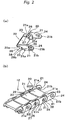
- Figs. 2(a) and 2(b) are perspective views illustrating the rigid unit forming the slide guide frame portion illustrated in Fig. 1 and a part of the slide guide frame portion, respectively.
- Figs. 3(a), 3(b), 3(c), 3(d), and 3(e) are a front view, a top view, a bottom view, a left side view, and a right side view of the rigid unit illustrated in Fig. 2(a) .
- the upper slide guide frame portion 12 is formed by the plurality of second rigid units 20, each of which includes a pair of side wall portions 21 disposed to face each other on the right and left sides and a bridge portion 22 linking both side wall portions 21 from the substantially center portion to one end portion on the left side.
- the adjacent two second rigid units are rotatably connected.
- the side wall portions 21 and the bridge portion 22 of the rigid unit 20 are members having the substantially flat shape.
- a depressed portion 23 which is depressed in a width direction w (see Fig. 3(e) ) of the second rigid unit 20 is formed in an approximately half portion 21a formed from the substantially center portion to the one end portion on the left side.
- the left end and the right end of the depressed portion 23 both are formed in an arc shape in front view.
- a through hole 24 which passes through in the width direction w of the second rigid unit 20 is formed in an approximately half portion 21b formed from the substantially center portion to the other end portion on the right side.
- One end on the right side of the approximately half portion 21b is formed in a semicircular shape in front view.
- a protrusion 25 is provided adjacent to the through hole 24 inwardly to the substantially center portion.
- an upper surface 25a is a flat surface extending in parallel to a length direction 1 (see Fig. 3(a) ) of the second rigid unit 20, and a lower surface 25b is an inclined surface which is inclined with respect to the upper surface 25a.
- An inclined degree of the lower surface 25b with respect to the upper surface 25a may be set to about 30°.
- a shaft 26 is provided in the substantially center portion to protrude toward the outside.
- a chamfer portion 27 inclined toward the inside in the width direction w of the second rigid unit 20 is formed in the one end portion on the left side of the side wall portion 21.
- a notch portion 28 cut in a height direction h (see Fig. 3(e) ) of the second rigid unit 20 is formed from the substantially center portion to the one end portion on the left side of the side wall portion 21.
- the notch portion 28 is formed by cutting the approximately half portion 21a from the lower surface to the half of the height of the approximately half portion 21a into an arc shape, and includes one end 28a in parallel with the length direction 1 of the second rigid unit 20 and the other end 28b in parallel with the height direction h of the second rigid unit 20.
- the adjacent two second rigid units 20 are connected such that the shaft 26 of one second rigid unit 20 is inserted into the through hole 24 of the other second rigid unit 20 from the inside. Since the chamfer portion 27 is formed in the shaft 26, the shaft 26 is easily inserted into the through hole 24, and thus the connection between the second rigid units 20 is easily realized.
- one second rigid unit 20 is freely rotated with respect to the other second rigid unit 20 within a range (about 60°) in which the upper surface 25a of the protrusion 25 abuts on one end 28a and the other end 28b of the notch portion 28. Therefore, the upper slide guide frame portion 12 formed by the plurality of second rigid units 20 in which the adjacent two units are rotatably connected has the flexibility.
- the upper slide guide frame portion 12 has the linearity.
- the width is reduced compared to the lower slide guide frame portion 13 formed by the first rigid units 14 as the present rigid units as illustrated in Fig. 1 .
- the second rigid unit 20 is reduced in dimension in the height direction h. Since a rotation limit of the second rigid unit 20 is determined by the protrusion 25 and the notch portion 28, the small protrusion 18 and the long hole 19 required for the first rigid unit 14 are eliminated. With the elimination of the long hole 19, the strength of the side wall portion 21 can be secured, and furthermore there is no need to take the strength of the small protrusion 18 into consideration.
- the connection strength made by the shaft 26 is sufficiently high, and the connection strength of the second rigid unit 20 in the upper slide guide frame portion 12 is sufficiently secured.
- the second rigid units 20 forming the upper slide guide frame portion 12 may be formed of a material having a good moldability such as resin or metal similarly to the present first rigid unit 14.
- the second rigid unit 20 is formed of the resin or the metal, the approximately half portion 21b of the side wall portion 21 can be expanded to the outside due to elasticity, and furthermore can be spontaneously restored to the original state. Therefore, the connection between the second rigid units 20 becomes easier.
- the upper slide guide frame portion 12 can be bent downward, and the lower slide guide frame portion 13 can be bent upward.
- the right ends of the upper slide guide frame portion 12 and the lower slide guide frame portion 13 both are configured by fixed ends, and fixed to the screen mounting frame portion 3.
- the left end serves as a free end 29 and disposed in the main body 8a of the screen mounting frame portion 8, and the upper slide guide frame portion 12 and the lower slide guide frame portion 13 can be stored in and drawn out of the inside of the main body 8a of the screen mounting frame portion 8.
- the inside of the main body 8a of the screen mounting frame portion 8 is partitioned into two portions: a first storage portion 30 in which the upper slide guide frame portion 12 is stored; and a second storage portion 31 in which the lower slide guide frame portion 13 is stored.
- the first storage portion 30 and the second storage portion 31 can be partitioned in the main body 8a by providing a rib or the like protruding into the main body 8a in the main body 8a in the height direction of the main body 8a.
- the first storage portion 30 is disposed on a side near the mounting portion of the screen 2 in the screen mounting frame portion 8, and the second storage portion 31 is disposed on a side away from the mounting portion of the screen 2.
- each free end 29 does not abut.
- the upper slide guide frame portion 12 and the lower slide guide frame portion 13 both are smoothly stored in the main body 8a of the screen mounting frame portion 8.
- the upper slide guide frame portion 12 and the lower slide guide frame portion 13 do not interfere with each other.
- the upper slide guide frame portion 12 and the lower slide guide frame portion 13 are connected to each other by a tensile member 32 appropriately selected from a wire material such as a cord or a wire. Since the upper slide guide frame portion 12 and the lower slide guide frame portion 13 are connected by the tensile member 32, movement amounts inside and outside the main body 8a become substantially equal according to the sliding of the screen mounting frame portion 8. Therefore, the slidable screen mounting frame portion 8 securely moves in parallel with respect to the fixed screen mounting frame portion 3.
- the tensile member 32 is looped inside the main body 8a of the screen mounting frame portion 8, wound around a direction changing member 33 provided on both upper and lower sides of the screen mounting frame portion 8, and folded back.
- the direction changing member 33 may be configured as a pulley of a barrel shape having a curved surface on which the tensile member 32 can be surrounded.
- a guide block 35 is provided in both upper and lower end portions where the upper slide guide frame portion 12 and the lower slide guide frame portion 13 move forward and backward.
- the guide block 35 includes a guide surface 34 therein to guide the bending of the upper slide guide frame portion 12 and the lower slide guide frame portion 13.
- the guide surface 34 is concavely bent from the right end to the lower end.
- the guide surface 34 is concavely bent from the right end to the upper end.
- the direction changing member 33 which folds back the tensile member 32 is attached.
- the direction changing member 33 on the upper side is disposed adjacent to the left side of the guide block 35 on the upper side.
- the upper slide guide frame portion 12 and the lower slide guide frame portion 13 are stored inside the main body 8a of the screen mounting frame portion 8 according to the sliding of the slidable screen mounting frame portion 8 in the horizontal direction, and drawn out therefrom.
- a portion drawn out of the screen mounting frame portion 8 has the linearity by the first rigid unit 14 and the second rigid unit 20 as described above.
- a latch 37 is disposed in the door stop frame 9.
- the latch 37 includes an engaging portion 38 which protrudes toward the screen mounting frame portion 8 and is bent downward.
- the latch 37 is applied with an elastic force of an installed spring 39, and can move upward and downward.
- a hanger (not illustrated) having an opening (not illustrated) which is engaged with the engaging portion 38 is provided.
- the engaging portion 38 of the latch 37 is inserted into the opening of the hanger, and the end is hung on the edge of the opening and engaged with the hanger.
- the screen mounting frame portion 8 is stopped in its movement against the elastic force of the coil spring 7 built in the roller pipe 4, and the screen device 1 can be stably kept in a closed state.
- the new slide guide frame portion having a reduced width is employed to the upper slide guide frame portion 12. Therefore, even when the present slide guide frame portion is employed to the lower slide guide frame portion 13, it is possible to reduce the width of the slidable screen mounting frame portion 8 where the upper slide guide frame portion 12 and the lower slide guide frame portion 13 are stored. Therefore, it is simply realized that an opening area is increased when the screen device 1 is completely opened. Further, in a case where the screen 2 is formed by net or lace, it is simply realized that an improvement of ventilation when the screen device 1 is completely closed.
- the details on the shape and the size of the rigid unit forming the new slide guide frame portion may be variously modified.
- the new slide guide frame portion can be similarly employed not only to the upper slide guide frame portion but also to the lower slide guide frame portion.
- the invention is not limited to a method of storing the screen into the roller pipe, and for example, it is possible to employ the screen which is pleated, contracted and stored between a pair of screen mounting frame portions.
- a reduced width of a slidable screen mounting frame portion is realized while securing a connection strength enough for a rigid unit.
Landscapes
- Engineering & Computer Science (AREA)
- Structural Engineering (AREA)
- Life Sciences & Earth Sciences (AREA)
- Insects & Arthropods (AREA)
- Pest Control & Pesticides (AREA)
- Architecture (AREA)
- Civil Engineering (AREA)
- Mechanical Engineering (AREA)
- Operating, Guiding And Securing Of Roll- Type Closing Members (AREA)
- Curtains And Furnishings For Windows Or Doors (AREA)
- Extensible Doors And Revolving Doors (AREA)
- Mirrors, Picture Frames, Photograph Stands, And Related Fastening Devices (AREA)
- Blinds (AREA)
- Overhead Projectors And Projection Screens (AREA)
- Transforming Electric Information Into Light Information (AREA)
- Devices For Indicating Variable Information By Combining Individual Elements (AREA)
Priority Applications (1)
| Application Number | Priority Date | Filing Date | Title |
|---|---|---|---|
| PL13852260T PL2915944T3 (pl) | 2012-11-05 | 2013-10-17 | Przesuwny segment ramy prowadnicy do ekranowych urządzeń |
Applications Claiming Priority (2)
| Application Number | Priority Date | Filing Date | Title |
|---|---|---|---|
| JP2012243837A JP6000807B2 (ja) | 2012-11-05 | 2012-11-05 | スクリーン装置のスライドガイド枠部 |
| PCT/JP2013/078157 WO2014069242A1 (ja) | 2012-11-05 | 2013-10-17 | スクリーン装置のスライドガイド枠部 |
Publications (3)
| Publication Number | Publication Date |
|---|---|
| EP2915944A1 EP2915944A1 (en) | 2015-09-09 |
| EP2915944A4 EP2915944A4 (en) | 2016-07-20 |
| EP2915944B1 true EP2915944B1 (en) | 2017-08-16 |
Family
ID=50627155
Family Applications (1)
| Application Number | Title | Priority Date | Filing Date |
|---|---|---|---|
| EP13852260.2A Active EP2915944B1 (en) | 2012-11-05 | 2013-10-17 | Slide guide frame section for screen devices |
Country Status (12)
| Country | Link |
|---|---|
| US (1) | US9487986B2 (pl) |
| EP (1) | EP2915944B1 (pl) |
| JP (1) | JP6000807B2 (pl) |
| CN (1) | CN104884725B (pl) |
| AU (1) | AU2013339447B2 (pl) |
| BR (1) | BR112015010137B1 (pl) |
| CA (1) | CA2890382C (pl) |
| ES (1) | ES2647781T3 (pl) |
| MX (1) | MX359750B (pl) |
| PL (1) | PL2915944T3 (pl) |
| RU (1) | RU2616918C2 (pl) |
| WO (1) | WO2014069242A1 (pl) |
Families Citing this family (15)
| Publication number | Priority date | Publication date | Assignee | Title |
|---|---|---|---|---|
| JP6320863B2 (ja) * | 2014-07-15 | 2018-05-09 | 株式会社メタコ | スクリーン装置 |
| JP6401019B2 (ja) * | 2014-10-21 | 2018-10-03 | 株式会社メタコ | スライドガイド枠とこれを用いたスクリーン装置 |
| JP6700738B2 (ja) * | 2015-11-24 | 2020-05-27 | 株式会社メタコ | 電動スクリーン装置 |
| SI3263820T1 (sl) * | 2016-06-28 | 2019-02-28 | Gabrijel Rejc | Motorno gnana in navpično premična dvižna vrata |
| PL3263819T3 (pl) * | 2016-06-28 | 2019-06-28 | Gabrijel Rejc | Ruchoma pionowo brama ze skrzydłem bramy |
| DE102016225079A1 (de) | 2016-12-15 | 2018-06-21 | Gabrijel Rejc Gmbh & Co. Kg | Tor mit einer Absturzsicherung |
| US11643864B2 (en) | 2018-01-23 | 2023-05-09 | Pella Corporation | Screen edge retention and screen rethreading features for a hidden screen assembly and a fenestration assembly |
| EP3567205B1 (en) | 2018-05-10 | 2021-04-14 | Palagina S.r.l. | Guide chain for fabric roller blind |
| CA3097254A1 (en) | 2019-10-30 | 2021-04-30 | Pella Corporation | Retractable screen system and fenestration assembly |
| US12000208B2 (en) | 2020-01-31 | 2024-06-04 | Pella Corporation | Integrated pleated screen assembly |
| CN115104883A (zh) * | 2021-03-17 | 2022-09-27 | 株式会社美达科 | 屏风装置 |
| US11505991B2 (en) * | 2021-03-24 | 2022-11-22 | Metaco Inc. | Screen device |
| EP4350117B1 (en) * | 2021-05-26 | 2025-07-09 | Metaco Inc. | Screen apparatus |
| WO2022249334A1 (ja) * | 2021-05-26 | 2022-12-01 | 株式会社メタコ | スクリーン装置 |
| PL4350115T3 (pl) * | 2021-06-02 | 2025-11-03 | Metaco Inc. | Struktura okablowania elementu napinającego w urządzeniu ekranowym |
Family Cites Families (25)
| Publication number | Priority date | Publication date | Assignee | Title |
|---|---|---|---|---|
| JPS6178989A (ja) | 1984-09-26 | 1986-04-22 | 新日軽株式会社 | 窓の密閉装置 |
| US4757852A (en) | 1985-10-25 | 1988-07-19 | Leon Jentof | Automatic mosquito curtain for windows and doors |
| JPH0663597B2 (ja) * | 1986-04-03 | 1994-08-22 | 敬之助 松谷 | 巻取り可能な伸縮構造体 |
| JP3424284B2 (ja) | 1993-11-24 | 2003-07-07 | 富士電機株式会社 | 配電盤の電気機器駆動軸装置 |
| JP3323461B2 (ja) | 1999-09-07 | 2002-09-09 | 株式会社メタコ | スクリーン装置 |
| US6186212B1 (en) * | 1998-06-11 | 2001-02-13 | Metaco Inc. | Screen device |
| JP3403652B2 (ja) * | 1998-11-06 | 2003-05-06 | 株式会社メタコ | スクリーン装置 |
| US6283193B1 (en) | 1999-07-06 | 2001-09-04 | Harry E. Finch | Adjustable tensioning arrangement for modular security door system |
| US6644378B2 (en) | 2001-11-02 | 2003-11-11 | Wayne-Dalton Corp. | Tensioning device for a door system |
| US20070012410A1 (en) | 2002-04-10 | 2007-01-18 | Canimex Inc. | Ratchet system for winding a rolling door assembly |
| WO2004071252A1 (en) | 2003-02-07 | 2004-08-26 | Pella Corporation | Retractable screen door components and method |
| JP2005023577A (ja) | 2003-06-30 | 2005-01-27 | Seiki Juko Kk | 巻取式スクリーン装置 |
| US6896027B2 (en) | 2003-07-15 | 2005-05-24 | Nci Building Systems, L.P. | Method and apparatus for suspending a door |
| CN100572736C (zh) * | 2003-08-27 | 2009-12-23 | 株式会社梅泰柯 | 帘装置 |
| JP4693366B2 (ja) | 2004-06-14 | 2011-06-01 | 株式会社メタコ | スクリーン装置 |
| WO2006038301A1 (ja) | 2004-10-07 | 2006-04-13 | Seiki Sogyo Co., Ltd. | 網戸用ネットガイド |
| JP4794373B2 (ja) * | 2006-06-23 | 2011-10-19 | 株式会社メタコ | スクリーン装置 |
| US20090008615A1 (en) * | 2007-06-07 | 2009-01-08 | High Arctic Energy Services Limited Partnership | Roller chain and sprocket system |
| US7810543B2 (en) * | 2007-12-11 | 2010-10-12 | Effe S.R.L. | Roller screen device |
| JP5358126B2 (ja) * | 2008-06-09 | 2013-12-04 | 株式会社メタコ | スクリーン装置 |
| AU2010201331B2 (en) * | 2009-04-02 | 2016-04-28 | Global Pleated Screens Pty Ltd | Pleat screen device |
| JP5284238B2 (ja) * | 2009-10-07 | 2013-09-11 | 株式会社メタコ | スクリーン装置 |
| US8336286B2 (en) * | 2010-02-10 | 2012-12-25 | Prince Castle LLC | Push chain with a bias spring to prevent buckling |
| US8302655B2 (en) | 2011-03-16 | 2012-11-06 | Macauto Industrial Co., Ltd. | Spring drive device for a sunshade assembly |
| JP2014081058A (ja) * | 2012-10-18 | 2014-05-08 | Tsubakimoto Chain Co | 押し引き両用チェーン、進退作動装置 |
-
2012
- 2012-11-05 JP JP2012243837A patent/JP6000807B2/ja active Active
-
2013
- 2013-10-17 RU RU2015117582A patent/RU2616918C2/ru active
- 2013-10-17 WO PCT/JP2013/078157 patent/WO2014069242A1/ja not_active Ceased
- 2013-10-17 CN CN201380057555.3A patent/CN104884725B/zh active Active
- 2013-10-17 MX MX2015005646A patent/MX359750B/es active IP Right Grant
- 2013-10-17 ES ES13852260.2T patent/ES2647781T3/es active Active
- 2013-10-17 EP EP13852260.2A patent/EP2915944B1/en active Active
- 2013-10-17 US US14/435,618 patent/US9487986B2/en active Active
- 2013-10-17 PL PL13852260T patent/PL2915944T3/pl unknown
- 2013-10-17 BR BR112015010137-2A patent/BR112015010137B1/pt active IP Right Grant
- 2013-10-17 AU AU2013339447A patent/AU2013339447B2/en active Active
- 2013-10-17 CA CA2890382A patent/CA2890382C/en active Active
Non-Patent Citations (1)
| Title |
|---|
| None * |
Also Published As
| Publication number | Publication date |
|---|---|
| JP6000807B2 (ja) | 2016-10-05 |
| PL2915944T3 (pl) | 2017-11-30 |
| BR112015010137B1 (pt) | 2021-06-01 |
| CN104884725A (zh) | 2015-09-02 |
| MX2015005646A (es) | 2015-08-20 |
| WO2014069242A1 (ja) | 2014-05-08 |
| BR112015010137A2 (pt) | 2019-12-17 |
| AU2013339447A1 (en) | 2015-06-18 |
| RU2015117582A (ru) | 2016-12-27 |
| MX359750B (es) | 2018-10-08 |
| ES2647781T3 (es) | 2017-12-26 |
| EP2915944A4 (en) | 2016-07-20 |
| JP2014091980A (ja) | 2014-05-19 |
| EP2915944A1 (en) | 2015-09-09 |
| US20150300067A1 (en) | 2015-10-22 |
| CA2890382A1 (en) | 2014-05-08 |
| RU2616918C2 (ru) | 2017-04-18 |
| US9487986B2 (en) | 2016-11-08 |
| CA2890382C (en) | 2020-08-25 |
| CN104884725B (zh) | 2016-11-02 |
| AU2013339447B2 (en) | 2017-04-20 |
Similar Documents
| Publication | Publication Date | Title |
|---|---|---|
| EP2915944B1 (en) | Slide guide frame section for screen devices | |
| CN1977087B (zh) | 帘装置 | |
| EP1959090B1 (en) | Foldable screen device | |
| JP5284239B2 (ja) | スクリーン装置 | |
| JP5602995B2 (ja) | スクリーン装置 | |
| CN102597406B (zh) | 隔离幕装置 | |
| EP2687786A2 (en) | Assembly of a door hinge of an oven of a household appliance with dampened closing | |
| US20240102340A1 (en) | Screen guide frame structure and screen device having same | |
| KR20120041056A (ko) | 태엽 스프링 구동형 방충망 장치 및 그의 롤 구동 유닛 | |
| IT201900002879A1 (it) | Dispositivo di tensionamento per zanzariere e tende avvolgibili | |
| JP6320863B2 (ja) | スクリーン装置 | |
| JP5601526B2 (ja) | 折畳み式横引きシャッター装置 | |
| KR102699030B1 (ko) | 창호 차폐 장치 | |
| JP7621133B2 (ja) | ロール網戸 | |
| KR20240041598A (ko) | 롤 스크린용 감속 어셈블리 | |
| KR20170014995A (ko) | 슬라이드레일 자동폐쇄장치 | |
| HK1133685A1 (en) | Screen device | |
| HK1133685B (en) | Screen device | |
| ITRN20060003A1 (it) | Dispositivo di sicurezza per serrande avvolgibili |
Legal Events
| Date | Code | Title | Description |
|---|---|---|---|
| PUAI | Public reference made under article 153(3) epc to a published international application that has entered the european phase |
Free format text: ORIGINAL CODE: 0009012 |
|
| 17P | Request for examination filed |
Effective date: 20150416 |
|
| AK | Designated contracting states |
Kind code of ref document: A1 Designated state(s): AL AT BE BG CH CY CZ DE DK EE ES FI FR GB GR HR HU IE IS IT LI LT LU LV MC MK MT NL NO PL PT RO RS SE SI SK SM TR |
|
| AX | Request for extension of the european patent |
Extension state: BA ME |
|
| DAX | Request for extension of the european patent (deleted) | ||
| RA4 | Supplementary search report drawn up and despatched (corrected) |
Effective date: 20160616 |
|
| RIC1 | Information provided on ipc code assigned before grant |
Ipc: E06B 9/54 20060101ALI20160610BHEP Ipc: E06B 3/92 20060101AFI20160610BHEP |
|
| GRAP | Despatch of communication of intention to grant a patent |
Free format text: ORIGINAL CODE: EPIDOSNIGR1 |
|
| INTG | Intention to grant announced |
Effective date: 20170425 |
|
| GRAS | Grant fee paid |
Free format text: ORIGINAL CODE: EPIDOSNIGR3 |
|
| GRAA | (expected) grant |
Free format text: ORIGINAL CODE: 0009210 |
|
| AK | Designated contracting states |
Kind code of ref document: B1 Designated state(s): AL AT BE BG CH CY CZ DE DK EE ES FI FR GB GR HR HU IE IS IT LI LT LU LV MC MK MT NL NO PL PT RO RS SE SI SK SM TR |
|
| REG | Reference to a national code |
Ref country code: GB Ref legal event code: FG4D |
|
| REG | Reference to a national code |
Ref country code: CH Ref legal event code: EP |
|
| REG | Reference to a national code |
Ref country code: IE Ref legal event code: FG4D |
|
| REG | Reference to a national code |
Ref country code: AT Ref legal event code: REF Ref document number: 919211 Country of ref document: AT Kind code of ref document: T Effective date: 20170915 |
|
| REG | Reference to a national code |
Ref country code: NL Ref legal event code: FP |
|
| REG | Reference to a national code |
Ref country code: DE Ref legal event code: R096 Ref document number: 602013025273 Country of ref document: DE |
|
| REG | Reference to a national code |
Ref country code: FR Ref legal event code: PLFP Year of fee payment: 5 |
|
| REG | Reference to a national code |
Ref country code: ES Ref legal event code: FG2A Ref document number: 2647781 Country of ref document: ES Kind code of ref document: T3 Effective date: 20171226 |
|
| REG | Reference to a national code |
Ref country code: LT Ref legal event code: MG4D |
|
| REG | Reference to a national code |
Ref country code: AT Ref legal event code: MK05 Ref document number: 919211 Country of ref document: AT Kind code of ref document: T Effective date: 20170816 |
|
| PG25 | Lapsed in a contracting state [announced via postgrant information from national office to epo] |
Ref country code: SE Free format text: LAPSE BECAUSE OF FAILURE TO SUBMIT A TRANSLATION OF THE DESCRIPTION OR TO PAY THE FEE WITHIN THE PRESCRIBED TIME-LIMIT Effective date: 20170816 Ref country code: AT Free format text: LAPSE BECAUSE OF FAILURE TO SUBMIT A TRANSLATION OF THE DESCRIPTION OR TO PAY THE FEE WITHIN THE PRESCRIBED TIME-LIMIT Effective date: 20170816 Ref country code: LT Free format text: LAPSE BECAUSE OF FAILURE TO SUBMIT A TRANSLATION OF THE DESCRIPTION OR TO PAY THE FEE WITHIN THE PRESCRIBED TIME-LIMIT Effective date: 20170816 Ref country code: FI Free format text: LAPSE BECAUSE OF FAILURE TO SUBMIT A TRANSLATION OF THE DESCRIPTION OR TO PAY THE FEE WITHIN THE PRESCRIBED TIME-LIMIT Effective date: 20170816 Ref country code: NO Free format text: LAPSE BECAUSE OF FAILURE TO SUBMIT A TRANSLATION OF THE DESCRIPTION OR TO PAY THE FEE WITHIN THE PRESCRIBED TIME-LIMIT Effective date: 20171116 |
|
| PG25 | Lapsed in a contracting state [announced via postgrant information from national office to epo] |
Ref country code: BG Free format text: LAPSE BECAUSE OF FAILURE TO SUBMIT A TRANSLATION OF THE DESCRIPTION OR TO PAY THE FEE WITHIN THE PRESCRIBED TIME-LIMIT Effective date: 20171116 Ref country code: IS Free format text: LAPSE BECAUSE OF FAILURE TO SUBMIT A TRANSLATION OF THE DESCRIPTION OR TO PAY THE FEE WITHIN THE PRESCRIBED TIME-LIMIT Effective date: 20171216 Ref country code: RS Free format text: LAPSE BECAUSE OF FAILURE TO SUBMIT A TRANSLATION OF THE DESCRIPTION OR TO PAY THE FEE WITHIN THE PRESCRIBED TIME-LIMIT Effective date: 20170816 Ref country code: LV Free format text: LAPSE BECAUSE OF FAILURE TO SUBMIT A TRANSLATION OF THE DESCRIPTION OR TO PAY THE FEE WITHIN THE PRESCRIBED TIME-LIMIT Effective date: 20170816 |
|
| REG | Reference to a national code |
Ref country code: GR Ref legal event code: EP Ref document number: 20170402447 Country of ref document: GR Effective date: 20180309 |
|
| PG25 | Lapsed in a contracting state [announced via postgrant information from national office to epo] |
Ref country code: RO Free format text: LAPSE BECAUSE OF FAILURE TO SUBMIT A TRANSLATION OF THE DESCRIPTION OR TO PAY THE FEE WITHIN THE PRESCRIBED TIME-LIMIT Effective date: 20170816 Ref country code: DK Free format text: LAPSE BECAUSE OF FAILURE TO SUBMIT A TRANSLATION OF THE DESCRIPTION OR TO PAY THE FEE WITHIN THE PRESCRIBED TIME-LIMIT Effective date: 20170816 |
|
| REG | Reference to a national code |
Ref country code: DE Ref legal event code: R097 Ref document number: 602013025273 Country of ref document: DE |
|
| PG25 | Lapsed in a contracting state [announced via postgrant information from national office to epo] |
Ref country code: SM Free format text: LAPSE BECAUSE OF FAILURE TO SUBMIT A TRANSLATION OF THE DESCRIPTION OR TO PAY THE FEE WITHIN THE PRESCRIBED TIME-LIMIT Effective date: 20170816 Ref country code: MC Free format text: LAPSE BECAUSE OF FAILURE TO SUBMIT A TRANSLATION OF THE DESCRIPTION OR TO PAY THE FEE WITHIN THE PRESCRIBED TIME-LIMIT Effective date: 20170816 Ref country code: SK Free format text: LAPSE BECAUSE OF FAILURE TO SUBMIT A TRANSLATION OF THE DESCRIPTION OR TO PAY THE FEE WITHIN THE PRESCRIBED TIME-LIMIT Effective date: 20170816 Ref country code: EE Free format text: LAPSE BECAUSE OF FAILURE TO SUBMIT A TRANSLATION OF THE DESCRIPTION OR TO PAY THE FEE WITHIN THE PRESCRIBED TIME-LIMIT Effective date: 20170816 |
|
| REG | Reference to a national code |
Ref country code: CH Ref legal event code: PL |
|
| PLBE | No opposition filed within time limit |
Free format text: ORIGINAL CODE: 0009261 |
|
| STAA | Information on the status of an ep patent application or granted ep patent |
Free format text: STATUS: NO OPPOSITION FILED WITHIN TIME LIMIT |
|
| 26N | No opposition filed |
Effective date: 20180517 |
|
| GBPC | Gb: european patent ceased through non-payment of renewal fee |
Effective date: 20171116 |
|
| REG | Reference to a national code |
Ref country code: IE Ref legal event code: MM4A |
|
| PG25 | Lapsed in a contracting state [announced via postgrant information from national office to epo] |
Ref country code: CH Free format text: LAPSE BECAUSE OF NON-PAYMENT OF DUE FEES Effective date: 20171031 Ref country code: LU Free format text: LAPSE BECAUSE OF NON-PAYMENT OF DUE FEES Effective date: 20171017 Ref country code: LI Free format text: LAPSE BECAUSE OF NON-PAYMENT OF DUE FEES Effective date: 20171031 |
|
| REG | Reference to a national code |
Ref country code: BE Ref legal event code: MM Effective date: 20171031 |
|
| PG25 | Lapsed in a contracting state [announced via postgrant information from national office to epo] |
Ref country code: SI Free format text: LAPSE BECAUSE OF FAILURE TO SUBMIT A TRANSLATION OF THE DESCRIPTION OR TO PAY THE FEE WITHIN THE PRESCRIBED TIME-LIMIT Effective date: 20170816 Ref country code: BE Free format text: LAPSE BECAUSE OF NON-PAYMENT OF DUE FEES Effective date: 20171031 |
|
| PG25 | Lapsed in a contracting state [announced via postgrant information from national office to epo] |
Ref country code: MT Free format text: LAPSE BECAUSE OF NON-PAYMENT OF DUE FEES Effective date: 20171017 |
|
| PG25 | Lapsed in a contracting state [announced via postgrant information from national office to epo] |
Ref country code: IE Free format text: LAPSE BECAUSE OF NON-PAYMENT OF DUE FEES Effective date: 20171017 |
|
| REG | Reference to a national code |
Ref country code: FR Ref legal event code: PLFP Year of fee payment: 6 |
|
| PG25 | Lapsed in a contracting state [announced via postgrant information from national office to epo] |
Ref country code: GB Free format text: LAPSE BECAUSE OF NON-PAYMENT OF DUE FEES Effective date: 20171116 |
|
| PG25 | Lapsed in a contracting state [announced via postgrant information from national office to epo] |
Ref country code: HU Free format text: LAPSE BECAUSE OF FAILURE TO SUBMIT A TRANSLATION OF THE DESCRIPTION OR TO PAY THE FEE WITHIN THE PRESCRIBED TIME-LIMIT; INVALID AB INITIO Effective date: 20131017 |
|
| PG25 | Lapsed in a contracting state [announced via postgrant information from national office to epo] |
Ref country code: CY Free format text: LAPSE BECAUSE OF FAILURE TO SUBMIT A TRANSLATION OF THE DESCRIPTION OR TO PAY THE FEE WITHIN THE PRESCRIBED TIME-LIMIT Effective date: 20170816 |
|
| PG25 | Lapsed in a contracting state [announced via postgrant information from national office to epo] |
Ref country code: MK Free format text: LAPSE BECAUSE OF FAILURE TO SUBMIT A TRANSLATION OF THE DESCRIPTION OR TO PAY THE FEE WITHIN THE PRESCRIBED TIME-LIMIT Effective date: 20170816 |
|
| PG25 | Lapsed in a contracting state [announced via postgrant information from national office to epo] |
Ref country code: PT Free format text: LAPSE BECAUSE OF FAILURE TO SUBMIT A TRANSLATION OF THE DESCRIPTION OR TO PAY THE FEE WITHIN THE PRESCRIBED TIME-LIMIT Effective date: 20170816 |
|
| PG25 | Lapsed in a contracting state [announced via postgrant information from national office to epo] |
Ref country code: HR Free format text: LAPSE BECAUSE OF FAILURE TO SUBMIT A TRANSLATION OF THE DESCRIPTION OR TO PAY THE FEE WITHIN THE PRESCRIBED TIME-LIMIT Effective date: 20170816 |
|
| PG25 | Lapsed in a contracting state [announced via postgrant information from national office to epo] |
Ref country code: AL Free format text: LAPSE BECAUSE OF FAILURE TO SUBMIT A TRANSLATION OF THE DESCRIPTION OR TO PAY THE FEE WITHIN THE PRESCRIBED TIME-LIMIT Effective date: 20170816 |
|
| PGFP | Annual fee paid to national office [announced via postgrant information from national office to epo] |
Ref country code: IT Payment date: 20250806 Year of fee payment: 13 |
|
| PGFP | Annual fee paid to national office [announced via postgrant information from national office to epo] |
Ref country code: NL Payment date: 20251027 Year of fee payment: 13 |
|
| PGFP | Annual fee paid to national office [announced via postgrant information from national office to epo] |
Ref country code: DE Payment date: 20251024 Year of fee payment: 13 |
|
| PGFP | Annual fee paid to national office [announced via postgrant information from national office to epo] |
Ref country code: FR Payment date: 20251031 Year of fee payment: 13 |
|
| PGFP | Annual fee paid to national office [announced via postgrant information from national office to epo] |
Ref country code: TR Payment date: 20251103 Year of fee payment: 13 Ref country code: GR Payment date: 20251029 Year of fee payment: 13 |
|
| PGFP | Annual fee paid to national office [announced via postgrant information from national office to epo] |
Ref country code: CZ Payment date: 20251024 Year of fee payment: 13 |
|
| PGFP | Annual fee paid to national office [announced via postgrant information from national office to epo] |
Ref country code: PL Payment date: 20251024 Year of fee payment: 13 |
|
| PGFP | Annual fee paid to national office [announced via postgrant information from national office to epo] |
Ref country code: ES Payment date: 20251103 Year of fee payment: 13 |