EP2915642A1 - Baumaschine - Google Patents
Baumaschine Download PDFInfo
- Publication number
- EP2915642A1 EP2915642A1 EP15150872.8A EP15150872A EP2915642A1 EP 2915642 A1 EP2915642 A1 EP 2915642A1 EP 15150872 A EP15150872 A EP 15150872A EP 2915642 A1 EP2915642 A1 EP 2915642A1
- Authority
- EP
- European Patent Office
- Prior art keywords
- bit
- tool
- tool changer
- chisel
- construction machine
- Prior art date
- Legal status (The legal status is an assumption and is not a legal conclusion. Google has not performed a legal analysis and makes no representation as to the accuracy of the status listed.)
- Granted
Links
Images


Classifications
-
- B—PERFORMING OPERATIONS; TRANSPORTING
- B28—WORKING CEMENT, CLAY, OR STONE
- B28D—WORKING STONE OR STONE-LIKE MATERIALS
- B28D1/00—Working stone or stone-like materials, e.g. brick, concrete or glass, not provided for elsewhere; Machines, devices, tools therefor
- B28D1/18—Working stone or stone-like materials, e.g. brick, concrete or glass, not provided for elsewhere; Machines, devices, tools therefor by milling, e.g. channelling by means of milling tools
- B28D1/186—Tools therefor, e.g. having exchangeable cutter bits
- B28D1/188—Tools therefor, e.g. having exchangeable cutter bits with exchangeable cutter bits or cutter segments
-
- E—FIXED CONSTRUCTIONS
- E01—CONSTRUCTION OF ROADS, RAILWAYS, OR BRIDGES
- E01C—CONSTRUCTION OF, OR SURFACES FOR, ROADS, SPORTS GROUNDS, OR THE LIKE; MACHINES OR AUXILIARY TOOLS FOR CONSTRUCTION OR REPAIR
- E01C23/00—Auxiliary devices or arrangements for constructing, repairing, reconditioning, or taking-up road or like surfaces
- E01C23/06—Devices or arrangements for working the finished surface; Devices for repairing or reconditioning the surface of damaged paving; Recycling in place or on the road
- E01C23/08—Devices or arrangements for working the finished surface; Devices for repairing or reconditioning the surface of damaged paving; Recycling in place or on the road for roughening or patterning; for removing the surface down to a predetermined depth high spots or material bonded to the surface, e.g. markings; for maintaining earth roads, clay courts or like surfaces by means of surface working tools, e.g. scarifiers, levelling blades
- E01C23/085—Devices or arrangements for working the finished surface; Devices for repairing or reconditioning the surface of damaged paving; Recycling in place or on the road for roughening or patterning; for removing the surface down to a predetermined depth high spots or material bonded to the surface, e.g. markings; for maintaining earth roads, clay courts or like surfaces by means of surface working tools, e.g. scarifiers, levelling blades using power-driven tools, e.g. vibratory tools
- E01C23/088—Rotary tools, e.g. milling drums
-
- E—FIXED CONSTRUCTIONS
- E21—EARTH OR ROCK DRILLING; MINING
- E21C—MINING OR QUARRYING
- E21C35/00—Details of, or accessories for, machines for slitting or completely freeing the mineral from the seam, not provided for in groups E21C25/00 - E21C33/00, E21C37/00 or E21C39/00
- E21C35/18—Mining picks; Holders therefor
-
- E—FIXED CONSTRUCTIONS
- E21—EARTH OR ROCK DRILLING; MINING
- E21C—MINING OR QUARRYING
- E21C35/00—Details of, or accessories for, machines for slitting or completely freeing the mineral from the seam, not provided for in groups E21C25/00 - E21C33/00, E21C37/00 or E21C39/00
- E21C35/18—Mining picks; Holders therefor
- E21C35/188—Mining picks; Holders therefor characterised by adaptations to use an extraction tool
Definitions
- the invention relates to a construction machine for processing ground surfaces, with a milling drum, on the surface of a plurality of chisel holders is arranged, wherein in a bit holder of the chisel holder a chisel, in particular a round shank chisel, is interchangeable added.
- Such trained as a road milling machine construction machine is from the DE 39 03 482 A1 known.
- road milling machines road surfaces can be milled off.
- the chisels wear out continuously. If the chisels have reached a certain state of wear, they must be replaced. For this purpose, it is necessary that a worker goes into the area of the milling drum and drives out the chisels from the chisel holders there. When removing the chisel, the worker uses a special Austreibdornes and a hammer. This can lead to injuries.
- the handling in the narrowed Fräswalzen Scheme is extremely cumbersome and requires great care to to minimize the risk of danger. After a chisel has been removed from its chisel holder, new unworn chisels must be inserted into the chisel holder. The exchange of the chisel is a very tedious and time-consuming job.
- the road milling machine has a Fräswalzenkasten in which a milling drum is housed protected. This is equipped with a variety of chisels. To facilitate the replacement of worn chisels, a seat can be swiveled into the working area of the milling drum when the machine is stationary. There, the worker can then take a seat comfortably and carry out the tool change.
- a change tool which automatically disassembles the one or more worn bits and / or mounts one or more unworn bits in the bit holder of the bit holder.
- the manual labor required to change the bits can be significantly reduced.
- the fact that the change process is at least partially automated, this can also be done faster, so less Machine downtimes arise.
- the health hazard and the physical strain on the operator are reduced.
- the tool changing device is a mechanical tool device, which is preferably arranged within the milling drum.
- Each bit holder according to the invention is associated with a respective tool changer of the tool changing device, wherein the tool changer can be firmly connected to the bit holder.
- the tool changers can also be connected to one another via a common control. For example, a machine operator can use this control to change individual chisels, groups of chisels or all chisels at the same time.
- the tool changer can be designed such that it engages the bit positively and / or non-positively and disassembled from the bit holder or mounted in this.
- the tool change can be further automated if it is provided that the tool changer conveys the dismantled bit directly or via a conveyor into a container or that the changing device is associated with a separating device, and that the singulator feeds bits from a storage unit of the tool changing device.
- the milling drum is associated with a detection device that continuously, in intervals or on default, the state of wear of the chisel or a part of the chisel or a single chisel checked, and that the detection device Upon reaching a predetermined state of wear, a tool change initiated or signaled.
- the wear detection can be designed, for example, such that at least one signal acquisition unit of the recognition device is assigned to at least one machine component directly or indirectly involved in the work process, that the signal acquisition unit detects an operating state of the machine component, and that the signal acquisition unit determines the state of wear via a signal processing arrangement ,
- Fig. 1 is a rotary body of a road milling machine, namely a milling drum 10 is shown.
- base parts 20 are arranged at a systematic spacing from one another.
- the base parts 20 are connected to the roller surface 11, preferably welded.
- the base parts 20 have a plug-in receptacle 21.
- a plug-in extension of a chisel holder 23 can be used.
- the chisel holder 23 is fixed to the base part 20 via a pressure screw 22.
- the chisel holder 23 has a bit receptacle 24, which is formed here as a bore.
- a chisel in this case a round shank chisel, are used.
- the bit 30 has a chisel head 31 to which a chisel tip 32 made of cemented carbide or a ceramic material is attached at the front.
- a shaft 33 connects, on which a clamping sleeve 34 is mounted.
- the clamping sleeve 34 is not axially displaceable, but rotatably connected in the circumferential direction with the shaft 33.
- the chisel head 31 lies with the interposition of a wear protection disk 35 on a mating surface of the chisel holder 23.
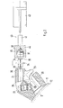
- Fig. 1 can recognize the bit holder 23 is associated with a tool changer 40 with a tool changer.
- the tool changer 40 has a servomotor 43, which drives a transmission member 41.
- the transmission member 41 is presently designed as a pull rod.
- the transmission member 41 carries a Austreibdorn 42.
- the Austreibdorn 42 can be introduced via the servo motor 43 in the bit holder 24. In this case, the mandrel penetrates into the bit receptacle 24 via the rear bore opening 25. He then meets the formed by the shaft 33 rear abutment surface.
- the servo motor 43 pulls the Austreibdorn 42 into the bit holder 24.
- the bit 30 together with a clamping sleeve 34 is pushed out of the bit receptacle 24.
- the servomotor 43 pushes the Austreibdorn 42 back out of the bit receptacle 24.
- the tool changer 40 can be adjusted by means of a, not shown in the drawing adjusting unit in the direction of the central longitudinal axis of the milling drum 10, for example, linear. It can then be gradually assigned to the individual bit holders 23 of the milling drum 10.
- the servomotor 43 moves not alone a Austreibdorn 42, but a plurality Austreibdorne 42 at the same time, so that a plurality of chisels 30 can be pushed out of their bit holders 23 with a setting operation.
- the milling drum 10 can be rotated via an auxiliary drive of an adjusting device.
- the auxiliary drive can be used when the milling drum 10 is lifted off the ground. Then it can be adjusted for tool change by means of the auxiliary drive.
- the auxiliary drive is also assigned a control unit. This rotates the milling drum 10 according to a predetermined program sequence, so that the chisel 30 or a part of the chisel 30 can be successively aligned with the tool changer 40.
- a tool changer 40 is shown which is used to mount an unworn bit 30 in the bit receptacle 24.
- the tool changer 40 in turn has a servomotor 43, which adjusts the transmission member 41 linearly.
- the transmission member 41 has a mounting bell 44. This is provided with a receptacle 45 in which the chisel 30 to be mounted is held with its chisel head 31.
- the tool changer 40 is accordingly assigned to the bit holder 23 by means of an actuating unit. In this case, then the shaft 33 is opposite the hole entry into the bit holder 24. Subsequently, the servo motor 43 is activated. The shaft 33 is then inserted into the bit receptacle 24.
- the in the Fig. 1 and 2 shown tool changer can be used individually or together on a road milling machine. If they are used together, then a fully automatic bit change can be performed.
- FIG. 3 a section of a milling drum 10 is shown.
- the milling drum 10 has a milling tube which forms the roll surface 11.
- bit holders 24 are introduced directly, so that the bit holder 23 are integrally connected to the Fräswalzenrohr.
- the bit receptacle 24 is formed by a bore. This is provided at its one bore end with a bore extension 26, which facilitates the insertion of the bit 30.
- a tool changer 40 is arranged at the other end of the bore.
- This can be designed as a hydraulic or pneumatic cylinder and have a linearly adjustable Austreibdorn 32.
- any other bit holder system especially in a swap-holder system, as shown in the FIGS. 1 and 2 is shown, insert.
- a chisel 30 is inserted in the bit holder 24 in the bit holder 24, a chisel 30 is inserted. This corresponds in its design in the FIGS. 1 and 2 shown chisel 30.
- the tool changer 40 To remove the bit 30 from its bit receptacle 24, the tool changer 40 is activated. Then the Austreibdorn 42 moves against the free end of the drill collar 33. The Austreibdorn 42 pushes the bit 30 in the direction of the central longitudinal axis of the bit holder 24 from.
- the tool changer 40 can also be used to reconnect a new unthreaded bit 30 to the extended expelling mandrel 42 and retract it into the bit receptacle 24 under the action of the change tool 40.
Landscapes
- Engineering & Computer Science (AREA)
- Mining & Mineral Resources (AREA)
- Mechanical Engineering (AREA)
- Geology (AREA)
- General Life Sciences & Earth Sciences (AREA)
- Geochemistry & Mineralogy (AREA)
- Life Sciences & Earth Sciences (AREA)
- Architecture (AREA)
- Civil Engineering (AREA)
- Structural Engineering (AREA)
- Automatic Tool Replacement In Machine Tools (AREA)
- Road Repair (AREA)
- Drilling And Exploitation, And Mining Machines And Methods (AREA)
- Processing Of Stones Or Stones Resemblance Materials (AREA)
- Soil Working Implements (AREA)
Abstract
Description
- Die Erfindung betrifft eine Baumaschine zum Bearbeiten von Bodenflächen, mit einer Fräswalze, auf deren Oberfläche eine Vielzahl von Meißelhaltern angeordnet ist, wobei in einer Meißelaufnahme des Meißelhalters ein Meißel, insbesondere ein Rundschaftmeißel, auswechselbar aufgenommen ist.
- Eine solche als Straßenfräsmaschine ausgebildete Baumaschine ist aus der
DE 39 03 482 A1 bekannt. Mit den Straßenfräsmaschinen können Straßenbeläge abgefräst werden. Im Laufe des Maschineneinsatzes verschleißen die Meißel kontinuierlich. Wenn die Meißel einen bestimmten Verschleißzustand erreicht haben, so müssen sie ausgetauscht werden. Hierzu ist es erforderlich, dass sich ein Arbeiter in den Bereich der Fräswalze begibt und dort die Meißel aus den Meißelhaltern austreibt. Beim Austreiben der Meißel bedient sich der Arbeiter eines speziellen Austreibdornes und eines Hammers. Dabei kann es zu Verletzungen kommen. Das Hantieren in dem eingeengten Fräswalzenbereich ist äußerst mühsam und bedarf großer Sorgfalt, um das Gefahrenrisiko zu minimieren. Nachdem ein Meißel aus seinem Meißelhalter entfernt wurde, müssen neue unverschlissene Meißel in die Meißelhalter eingesetzt werden. Der Tausch der Meißel stellt eine sehr mühsame und zeitaufwendige Arbeit dar. - Aus der
DE 32 23 761 C2 und derUS 3,342,531 sind manuell betätigbare Wechselwerkzeuge bekannt. Sie weisen einen Ansatz auf, der in eine umlaufende Nut im Meißel formschlüssig eingreift. Die Meißel können dann aus dem zugeordneten Meißelhalter ausgehebelt werden. Der Auswechselvorgang wird damit zwar erleichtert, jedoch ist die Arbeit an der Fräswalze dennoch gefährlich und mühsam. - Aus der
EP 1 167 626 A1 ist eine Straßenfräsmaschine bekannt. Die Straßenfräsmaschine besitzt einen Fräswalzenkasten, in dem eine Fräswalze geschützt untergebracht ist. Diese ist mit einer Vielzahl von Meißeln bestückt. Um den Austausch verschlissener Meißel zu erleichtern, kann bei stehender Maschine ein Sitz in den Arbeitsbereich der Fräswalze geschwenkt werden. Dort kann der Arbeiter dann bequem Platz nehmen und den Werkzeugwechsel durchführen. - Es ist Aufgabe der Erfindung, eine Straßenfräsmaschine der eingangs erwähnten Art zu schaffen, bei der das Auswechseln der Meißel vereinfacht ist.
- Diese Aufgabe wird mit den Merkmalen der Ansprüche gelöst.
- Erfindungsgemäß wird somit ein Wechselwerkzeug vorgeschlagen, das den oder mehrere verschlissenen Meißel automatisch demontiert und/oder einen oder mehrere unverschlissenen Meißel in der Meißelhalteraufnahme der Meißelhalter montiert. Auf diese Weise kann die manuelle Arbeit, die zum Wechseln der Meißel nötig ist, deutlich reduziert werden. Dadurch, dass der Wechselvorgang zumindest teilweise automatisiert ist, kann dieser auch schneller durchgeführt werden, sodass weniger Maschinenstillstandszeiten entstehen. Weiterhin werden mit der erfindungsgemäßen Anordnung auch die Gesundheitsgefahr und die körperliche Belastung des Maschinisten reduziert.
- Die Werkzeugwechselvorrichtung ist eine mechanische Werkzeugvorrichtung, die vorzugsweise innerhalb der Fräswalze angeordnet ist. Jedem Meißelhalter ist erfindungsgemäß jeweils ein Werkzeugwechsler der Werkzeugwechseleinrichtung zugeordnet, wobei der Werkzeugwechsler fest mit dem Meißelhalter verbunden sein kann. Die Werkzeugwechsler können auch über eine gemeinsame Steuerung miteinander verbunden sein. Über diese Steuerung kann ein Maschinenführer beispielsweise gezielt einzelne Meißel, Gruppen von Meißeln oder alle Meißel gleichzeitig wechseln.
- Der Werkzeugwechsler kann derart ausgelegt sein, dass er den Meißel form- und/oder kraftschlüssig angreift und aus dem Meißelhalter demontiert oder in diesen montiert.
- Der Werkzeugwechsel kann weiter automatisiert werden, wenn vorgesehen ist, dass die Werkzeugwechseleinrichtung die demontierten Meißel direkt oder über eine Fördereinrichtung in einen Behälter befördert oder dass der Wechseleinrichtung eine Vereinzelungseinrichtung zugeordnet ist, und dass die Vereinzelungseinrichtung Meißel aus einer Bevorratungseinheit der Werkzeugwechseleinrichtung zufördert.
- Eine optimale Ausnutzung der Werkzeugstandzeit kann dann erreicht werden, wenn vorgesehen ist, dass der Fräswalze eine Erkennungseinrichtung zugeordnet ist, die kontinuierlich, in Intervallen oder auf Vorgabe, den Verschleißzustand der Meißel oder eines Teils der Meißel oder eines einzelnen Meißels überprüft, und dass die Erkennungseinrichtung bei Erreichen eines vorgegebenen Verschleißzustandes einen Werkzeugwechsel initiiert oder signalisiert.
- Die Verschleißerkennung kann dabei beispielsweise so gestaltet sein, dass mindestens eine Signalaufnahmeeinheit der Erkennungseinrichtung wenigstens einem am Arbeitsprozess direkt oder indirekt beteiligten Maschinen-Bauteil zugeordnet ist, dass die Signalaufnahmeeinheit einen Betriebszustand des Maschinen-Bauteils erfasst, und dass die Signalaufnahmeeinheit über eine Signalverarbeitungsanordnung den Verschleißzustand ermittelt.
- Die Erfindung wird im Folgenden anhand von Zeichnungen dargestellt. Es zeigen:
- Fig. 1
- eine Fräswalze einer Straßenfräsmaschine mit einem darauf montierten Meißelhalter und einer nicht erfindungsgemäßen Werkzeugwechseleinrichtung in Seitenansicht und Teildarstellung,
- Fig. 2
- die Fräswalze gemäß
Fig. 1 mit einer nicht erfindungsgemäßen Werkzeugwechseleinrichtung zum Montieren von unverschlissenen Meißeln und - Fig. 3
- In Seitenansicht und im Schnitt eine Fräswalze mit einem einteilig angeformten Meißelhalter.
- In der
Fig. 1 ist ein Rotationskörper einer Straßenfräsmaschine, nämlich eine Fräswalze 10 dargestellt. Auf der Walzenoberfläche 11 der Fräswalze 10 sind in systematischer Teilung zueinander beabstandet Basisteile 20 angeordnet. Die Basisteile 20 sind mit der Walzenoberfläche 11 verbunden, vorzugsweise verschweißt. Die Basisteile 20 weisen eine Steckaufnahme 21 auf. In die Steckaufnahme 21 kann ein Steckansatz eines Meißelhalters 23 eingesetzt werden. Die Fixierung des Meißelhalters 23 an dem Basisteil 20 erfolgt über eine Druckschraube 22. Der Meißelhalter 23 besitzt eine Meißelaufnahme 24, die vorliegend als Bohrung ausgebildet ist. In die Bohrung kann ein Meißel, vorliegend ein Rundschaftmeißel, eingesetzt werden. Der Meißel 30 besitzt einen Meißelkopf 31, an dem eine Meißelspitze 32, bestehend aus Hartmetall oder einem Keramikmaterial, frontseitig befestigt ist. An den Meißelkopf 31 schließt sich ein Schaft 33 an, auf den eine Spannhülse 34 aufgezogen ist. Die Spannhülse 34 ist nicht axial verschiebbar, jedoch in Umfangsrichtung drehbar mit dem Schaft 33 verbunden. - Der Meißelkopf 31 liegt unter Zwischenlage einer Verschleißschutzscheibe 35 auf einer Gegenfläche des Meißelhalters 23 auf.
- Wie
Fig. 1 erkennen lässt, ist dem Meißelhalter 23 eine Werkzeugwechseleinrichtung mit einem Werkzeugwechsler 40 zugeordnet. Der Werkzeugwechsler 40 besitzt einen Stellmotor 43, der ein Übertragungsglied 41 antreibt. Das Übertragungsglied 41 ist vorliegend als Zugstange ausgebildet. An dem, dem Stellmotor 43 abgewandten Ende, trägt das Übertragungsglied 41 einen Austreibdorn 42. Der Austreibdorn 42 kann über den Stellmotor 43 in die Meißelaufnahme 24 eingeführt werden. Hierbei dringt der Dorn über die rückwärtige Bohrungsöffnung 25 in die Meißelaufnahme 24 ein. Er trifft dann auf die von dem Schaft 33 gebildete rückwärtige Stoßfläche. Der Stellmotor 43 zieht den Austreibdorn 42 in die Meißelaufnahme 24 hinein. Dabei wird der Meißel 30 samt einer Spannhülse 34 aus der Meißelaufnahme 24 herausgeschoben. Nachdem der Meißel 30 aus der Meißelaufnahme 24 herausbewegt wurde, schiebt der Stellmotor 43 den Austreibdorn 42 wieder aus der Meißelaufnahme 24 heraus. - Der Werkzeugwechsler 40 kann mittels einer, in der Zeichnung nicht dargestellten Stelleinheit in Richtung der Mittellängsachse der Fräswalze 10 beispielsweise linienförmig verstellt werden. Er lässt sich dann nach und nach den einzelnen Meißelhaltern 23 der Fräswalze 10 zuordnen. Vorteilhafter Weise bewegt der Stellmotor 43 nicht alleine einen Austreibdorn 42, sondern mehrere Austreibdorne 42 gleichzeitig, so dass mit einem Stellvorgang mehrere Meißel 30 aus ihren Meißelhaltern 23 herausgeschoben werden können.
- Es ist auch denkbar, dass die Fräswalze 10 über einen Hilfsantrieb einer Verstelleinrichtung gedreht werden kann. Der Hilfsantrieb kann dann zum Einsatz kommen, wenn die Fräswalze 10 vom Boden abgehoben ist. Dann lässt sie sich zum Werkzeugwechsel mittels des Hilfsantriebes verstellen. Vorteilhafter Weise ist dem Hilfsantrieb auch eine Steuereinheit zugeordnet. Diese dreht die Fräswalze 10 nach einem vorgegebenen Programmablauf, so dass die Meißel 30 oder ein Teil der Meißel 30 nacheinander auf den Werkzeugwechsler 40 ausgerichtet werden können.
- In
Fig. 2 ist ein Werkzeugwechsler 40 dargestellt, der zur Montage eines unverschlissenen Meißels 30 in der Meißelaufnahme 24 verwendet wird. Der Werkzeugwechsler 40 besitzt wiederum einen Stellmotor 43, der das Übertragungsglied 41 linear verstellt. Das Übertragungsglied 41 weist eine Montageglocke 44 auf. Diese ist mit einer Aufnahme 45 versehen, in der der zu montierende Meißel 30 mit seinem Meißelkopf 31 gehalten ist. Der Werkzeugwechsler 40 wird dementsprechend dem Meißelhalter 23 mittels einer Stelleinheit zugeordnet. Dabei steht dann der Schaft 33 gegenüberliegend dem Bohrungseintritt in die Meißelaufnahme 24. Anschließend wird der Stellmotor 43 aktiviert. Der Schaft 33 wird dann in die Meißelaufnahme 24 eingeschoben. Die Einfädelbewegung des Schaftes 33 in die Meißelaufnahme 24 wird mittels einer konischen Bohrungserweiterung 26 erleichtert. Nachdem der Meißel 30 in den Meißelhalter 23 montiert wurde, wird der Meißelkopf 31 von der Montageglocke 44 freigegeben. Der Stellmotor 43 bewegt sich wieder in seine Ausgangslage und steht dann für den nächsten Montagevorgang zur Verfügung. - Die in den
Fig. 1 und2 dargestellten Werkzeugwechsler können einzeln oder gemeinsam an einer Straßenfräse verwendet werden. Wenn sie gemeinsam Verwendung finden, so kann ein vollautomatischer Meißelwechsel durchgeführt werden. - In der
Figur 3 ist ein Abschnitt einer Fräswalze 10 gezeigt. Die Fräswalze 10 besitzt ein Fräswalzrohr, das die Walzenoberfläche 11 bildet. In das Fräswalzenrohr sind Meißelaufnahmen 24 direkt eingebracht, so dass die Meißelhalter 23 einteilig mit dem Fräswalzenrohr verbunden sind. Die Meißelaufnahme 24 wird von einer Bohrung gebildet. Diese ist an ihrem einen Bohrungsende mit einer Bohrungserweiterung 26 versehen, die das Einsetzen des Meißels 30 erleichtert. Am anderen Ende der Bohrung ist ein Werkzeugwechsler 40 angeordnet. Dieser kann als Hydraulik- oder Pneumatikzylinder ausgebildet sein und einen linear verstellbaren Austreibdorn 32 aufweisen. Selbstverständlich lässt sich die in derFigur 3 angegebene Werkzeugwechseleinrichtung auch an einem beliebigen anderen Meißelhaltersystem, insbesondere bei einem Wechselhaltersystem, wie es in denFiguren 1 und2 dargestellt ist, einsetzen. - In die Meißelaufnahme 24 ist ein Meißel 30 eingesetzt. Dieser entspricht in seiner Bauart den in den
Figuren 1 und2 gezeigten Meißel 30. - Um den Meißel 30 aus seiner Meißelaufnahme 24 zu entfernen, wird der Werkzeugwechsler 40 aktiviert. Dann bewegt sich der Austreibdorn 42 gegen das freie Ende des Meißelschaftes 33. Der Austreibdorn 42 schiebt den Meißel 30 in Richtung der Mittel-Längsachse der Meißelaufnahme 24 aus. Der Werkzeugwechsler 40 kann auch dazu verwendet werden, einen neuen unverschlissenen Meißel 30 wieder an den ausgefahrenen Austreibdorn 42 angekoppelt und unter Einwirkung des Wechselwerkzeuges 40 in die Meißelaufnahme 24 eingezogen.
Claims (7)
- Baumaschine zum Bearbeiten von Bodenflächen, mit einer Fräswalze (10), auf deren Oberfläche eine Vielzahl von Meißelhaltern (23) angeordnet sind, wobei in einer Meißelaufnahme (24) des Meißelhalters (23) ein Meißel (30), insbesondere ein Rundschaftmeißel, auswechselbar aufgenommen ist, wobei der Fräswalze (10) eine Werkzeugwechseleinrichtung, die eine mechanischen Werkzeugvorrichtung ist, zugeordnet ist und die mindestens einen Werkzeugwechsler (40) aufweist, der den oder die Meißel (30) demontieren und/oder montieren kann,
dadurch gekennzeichnet,
dass jedem Meißelhalter (23) jeweils ein Werkzeugwechsler (40) der Werkzeugwechseleinrichtung zugeordnet ist,
und dass die Werkzeugwechseleinrichtung im Inneren der Fräswalze (10) angeordnet ist.
oder dass jedem Meißelhalter (23) jeweils ein Werkzeugwechsler (40) der Werkzeugwechseleinrichtung zugeordnet ist,
und dass die Werkzeugwechsler über eine gemeinsame Steuerung miteinander verbunden sind. - Baumaschine nach Anspruch 1,
dadurch gekennzeichnet,
dass der Werkzeugwechsler (40) fest mit dem Meißelhalter (23) verbunden ist. - Baumaschine nach Anspruch 1 oder 2,
dadurch gekennzeichnet, dass der Werkzeugwechsler (40), einen Ansatz aufweist, der an einer Formfläche des Meißels (30) angreift, und dass der Ansatz den Meißel (30) aus der Meißelaufnahme (24) auszieht oder herausschiebt bzw. in die Meißelaufnahme (24) hineinschiebt oder hineinzieht, oder dass der Werkzeugwechsler (40) kraftschlüssig an dem Meißel (30) angreift. - Baumaschine nach einem der Ansprüche 1 bis 3,
dadurch gekennzeichnet,
dass die Werkzeugwechseleinrichtung die demontierten Meißel (30) direkt oder über eine Fördereinrichtung in einen Behälter befördert. - Baumaschine nach einem der Ansprüche 1 bis 4,
dadurch gekennzeichnet,
dass der Werkzeugwechseleinrichtung eine Vereinzelungseinrichtung zugeordnet ist,
und dass die Vereinzelungseinrichtung Meißel (30) aus einer Bevorratungseinheit der Werkzeugwechseleinrichtung zufördert. - Baumaschine nach einem der Ansprüche 1 bis 5,
dadurch gekennzeichnet,
dass der Fräswalze (10) eine Erkennungseinrichtung zugeordnet ist, die kontinuierlich, in Intervallen oder auf Vorgabe, den Verschleißzustand der Meißel (30) oder eines Teils der Meißel (30) oder eines einzelnen Meißels (30) überprüft, und dass die Erkennungseinrichtung bei Erreichen eines vorgegebenen Verschleißzustandes einen Werkzeugwechsel initiiert oder signalisiert. - Baumaschine nach Anspruch 6,
dadurch gekennzeichnet,
dass mindestens eine Signalaufnahmeeinheit der Erkennungseinrichtung wenigstens einem am Arbeitsprozess direkt oder indirekt beteiligten Maschinen-Bauteil zugeordnet ist, dass die Signalaufnahmeeinheit einen Betriebszustand des Maschinen-Bauteils erfasst, und
dass die Signalaufnahmeeinheit über eine Signalverarbeitungsanordnung den Verschleißzustand ermittelt.
Applications Claiming Priority (2)
| Application Number | Priority Date | Filing Date | Title |
|---|---|---|---|
| DE10331970A DE10331970B4 (de) | 2003-07-14 | 2003-07-14 | Baumaschine |
| EP04727518.5A EP1646484B1 (de) | 2003-07-14 | 2004-04-15 | Baumaschine |
Related Parent Applications (2)
| Application Number | Title | Priority Date | Filing Date |
|---|---|---|---|
| EP04727518.5A Division EP1646484B1 (de) | 2003-07-14 | 2004-04-15 | Baumaschine |
| EP04727518.5A Division-Into EP1646484B1 (de) | 2003-07-14 | 2004-04-15 | Baumaschine |
Publications (2)
| Publication Number | Publication Date |
|---|---|
| EP2915642A1 true EP2915642A1 (de) | 2015-09-09 |
| EP2915642B1 EP2915642B1 (de) | 2017-06-28 |
Family
ID=34041873
Family Applications (3)
| Application Number | Title | Priority Date | Filing Date |
|---|---|---|---|
| EP04727518.5A Expired - Lifetime EP1646484B1 (de) | 2003-07-14 | 2004-04-15 | Baumaschine |
| EP09003594.0A Expired - Lifetime EP2060375B1 (de) | 2003-07-14 | 2004-04-15 | Verfahren zum Auswechseln von Meißel |
| EP15150872.8A Expired - Lifetime EP2915642B1 (de) | 2003-07-14 | 2004-04-15 | Baumaschine |
Family Applications Before (2)
| Application Number | Title | Priority Date | Filing Date |
|---|---|---|---|
| EP04727518.5A Expired - Lifetime EP1646484B1 (de) | 2003-07-14 | 2004-04-15 | Baumaschine |
| EP09003594.0A Expired - Lifetime EP2060375B1 (de) | 2003-07-14 | 2004-04-15 | Verfahren zum Auswechseln von Meißel |
Country Status (9)
| Country | Link |
|---|---|
| US (1) | US7401862B2 (de) |
| EP (3) | EP1646484B1 (de) |
| JP (1) | JP4714146B2 (de) |
| CN (1) | CN1816432B (de) |
| AU (1) | AU2004255307B2 (de) |
| BR (1) | BRPI0412551B1 (de) |
| DE (1) | DE10331970B4 (de) |
| RU (1) | RU2332538C2 (de) |
| WO (1) | WO2005005119A1 (de) |
Families Citing this family (63)
| Publication number | Priority date | Publication date | Assignee | Title |
|---|---|---|---|---|
| DE10221764C1 (de) * | 2002-05-15 | 2003-11-27 | Wirtgen Gmbh | Halterung für einen Schaftmeißel |
| EP1621685A1 (de) * | 2004-07-27 | 2006-02-01 | BITELLI S.p.A. | Werkzeug Abziehsystem für Schrämmeissel auf rotierenden Schneidköpfen |
| EP2322717A3 (de) * | 2006-12-22 | 2011-06-29 | Caterpillar Paving Products Inc. | Oberflächenbehandlungsmaschine |
| DE202007010047U1 (de) * | 2007-07-02 | 2007-09-27 | Wirtgen Gmbh | Werkzeug |
| DE102007030658A1 (de) * | 2007-07-02 | 2009-01-15 | Betek Bergbau- Und Hartmetalltechnik Karl-Heinz Simon Gmbh & Co. Kg | Schaftmeißel |
| AU2012203728B2 (en) * | 2008-05-26 | 2014-11-06 | Wirtgen Gmbh | Tool for removing a chisel |
| DE102008025071A1 (de) | 2008-05-26 | 2009-12-03 | Wirtgen Gmbh | Werkzeug zur Demontage eines Meißels |
| RU2472929C1 (ru) * | 2008-11-07 | 2013-01-20 | Брэдкен Ресорсиз Пти Лимитед | Крепление для сменного инструмента |
| DE102009014730B3 (de) * | 2009-03-25 | 2010-10-28 | Wirtgen Gmbh | Auswerfer bzw. Auswerfereinheit für eine Straßenfräsmaschine oder dergleichen |
| US8469456B2 (en) | 2009-03-25 | 2013-06-25 | Wirtgen Gmbh | Ejector unit for a road milling machine or the like |
| DE102009014729B3 (de) * | 2009-03-25 | 2010-11-04 | Wirtgen Gmbh | Auswerfer für eine Straßenfräsmaschine oder dergleichen |
| US8128177B2 (en) * | 2010-02-08 | 2012-03-06 | Wirtgen Gmbh | Adaptive advance drive control for milling machine |
| US10385689B1 (en) | 2010-08-27 | 2019-08-20 | The Sollami Company | Bit holder |
| US9879531B2 (en) | 2014-02-26 | 2018-01-30 | The Sollami Company | Bit holder shank and differential interference between the shank distal portion and the bit holder block bore |
| US10370966B1 (en) * | 2014-04-23 | 2019-08-06 | The Sollami Company | Rear of base block |
| US11261731B1 (en) | 2014-04-23 | 2022-03-01 | The Sollami Company | Bit holder and unitary bit/holder for use in shortened depth base blocks |
| US10072501B2 (en) | 2010-08-27 | 2018-09-11 | The Sollami Company | Bit holder |
| US10337324B2 (en) | 2015-01-07 | 2019-07-02 | The Sollami Company | Various bit holders and unitary bit/holders for use with shortened depth bit holder blocks |
| US10598013B2 (en) | 2010-08-27 | 2020-03-24 | The Sollami Company | Bit holder with shortened nose portion |
| USD669505S1 (en) * | 2011-11-23 | 2012-10-23 | Wirtgen Gmbh | Chisel holder bar |
| USD677285S1 (en) * | 2011-11-23 | 2013-03-05 | Wirtgen Gmbh | Chisel holder bar |
| DE102011119935A1 (de) * | 2011-12-01 | 2013-06-06 | Bomag Gmbh | Antriebsvorrichtung in einer selbstfahrenden Baumaschine |
| EP2685007B1 (de) | 2012-07-10 | 2015-01-07 | BAUER Maschinen GmbH | Fräsrad für eine Schlitzwandfräse |
| US10260342B1 (en) | 2012-10-19 | 2019-04-16 | The Sollami Company | Combination polycrystalline diamond bit and bit holder |
| US10180065B1 (en) | 2015-10-05 | 2019-01-15 | The Sollami Company | Material removing tool for road milling mining and trenching operations |
| US10105870B1 (en) | 2012-10-19 | 2018-10-23 | The Sollami Company | Combination polycrystalline diamond bit and bit holder |
| US9909416B1 (en) | 2013-09-18 | 2018-03-06 | The Sollami Company | Diamond tipped unitary holder/bit |
| US10107097B1 (en) | 2012-10-19 | 2018-10-23 | The Sollami Company | Combination polycrystalline diamond bit and bit holder |
| US9988903B2 (en) | 2012-10-19 | 2018-06-05 | The Sollami Company | Combination polycrystalline diamond bit and bit holder |
| US10323515B1 (en) | 2012-10-19 | 2019-06-18 | The Sollami Company | Tool with steel sleeve member |
| DE102012024770B4 (de) * | 2012-12-18 | 2024-03-14 | Bomag Gmbh | Selbstfahrende Baumaschine |
| DE102013008618B4 (de) * | 2013-05-21 | 2020-08-27 | Bomag Gmbh | Werkzeugverbund für eine Fräswalze, Fräswerkzeughalter und Fräswalze |
| US10577931B2 (en) | 2016-03-05 | 2020-03-03 | The Sollami Company | Bit holder (pick) with shortened shank and angular differential between the shank and base block bore |
| US10415386B1 (en) | 2013-09-18 | 2019-09-17 | The Sollami Company | Insertion-removal tool for holder/bit |
| US10876402B2 (en) | 2014-04-02 | 2020-12-29 | The Sollami Company | Bit tip insert |
| US9976418B2 (en) | 2014-04-02 | 2018-05-22 | The Sollami Company | Bit/holder with enlarged ballistic tip insert |
| US10794181B2 (en) | 2014-04-02 | 2020-10-06 | The Sollami Company | Bit/holder with enlarged ballistic tip insert |
| US10767478B2 (en) | 2013-09-18 | 2020-09-08 | The Sollami Company | Diamond tipped unitary holder/bit |
| US10633971B2 (en) | 2016-03-07 | 2020-04-28 | The Sollami Company | Bit holder with enlarged tire portion and narrowed bit holder block |
| US10995613B1 (en) | 2013-09-18 | 2021-05-04 | The Sollami Company | Diamond tipped unitary holder/bit |
| US10968739B1 (en) | 2013-09-18 | 2021-04-06 | The Sollami Company | Diamond tipped unitary holder/bit |
| US10947844B1 (en) | 2013-09-18 | 2021-03-16 | The Sollami Company | Diamond Tipped Unitary Holder/Bit |
| US11168563B1 (en) | 2013-10-16 | 2021-11-09 | The Sollami Company | Bit holder with differential interference |
| US11339656B1 (en) | 2014-02-26 | 2022-05-24 | The Sollami Company | Rear of base block |
| US11339654B2 (en) | 2014-04-02 | 2022-05-24 | The Sollami Company | Insert with heat transfer bore |
| US11891895B1 (en) | 2014-04-23 | 2024-02-06 | The Sollami Company | Bit holder with annular rings |
| DE102014011195C5 (de) * | 2014-07-28 | 2025-10-16 | Bomag Gmbh | Bodenfräsmaschine mit von einem Wartungsmotor betriebenem Kompressor und Verfahren zum Betrieb einer solchen Bodenfräsmaschine |
| US10502056B2 (en) | 2015-09-30 | 2019-12-10 | The Sollami Company | Reverse taper shanks and complementary base block bores for bit assemblies |
| US10612376B1 (en) | 2016-03-15 | 2020-04-07 | The Sollami Company | Bore wear compensating retainer and washer |
| DE102016108808A1 (de) * | 2016-05-12 | 2017-11-16 | Betek Gmbh & Co. Kg | Meißel mit einem Stützelement mit einem Zentrieransatz |
| US10876401B1 (en) | 2016-07-26 | 2020-12-29 | The Sollami Company | Rotational style tool bit assembly |
| US11187080B2 (en) | 2018-04-24 | 2021-11-30 | The Sollami Company | Conical bit with diamond insert |
| US10968738B1 (en) | 2017-03-24 | 2021-04-06 | The Sollami Company | Remanufactured conical bit |
| US12491611B2 (en) * | 2017-09-11 | 2025-12-09 | Steven Gerard Verkley | Bit driver and method for its use |
| US11279012B1 (en) | 2017-09-15 | 2022-03-22 | The Sollami Company | Retainer insertion and extraction tool |
| DE102017130800A1 (de) * | 2017-12-20 | 2019-06-27 | Wirtgen Gmbh | Werkzeug für die Montage eines Meißels an und/oder die Demontage eine Meißels von einem Meißelhaltersystem einer Fräsmaschine |
| US11103939B2 (en) | 2018-07-18 | 2021-08-31 | The Sollami Company | Rotatable bit cartridge |
| CN108951390A (zh) * | 2018-09-03 | 2018-12-07 | 徐州徐工筑路机械有限公司 | 一种铣刨装置用卸刀弯头及气动卸刀工具 |
| US10857633B2 (en) | 2018-09-07 | 2020-12-08 | Caterpillar Paving Products Inc. | Toolholder with provisions for bit removal |
| US11274423B2 (en) * | 2019-02-22 | 2022-03-15 | G. Dennis Gordon | Road grader blade teeth removal apparatus |
| US12345158B1 (en) | 2019-06-20 | 2025-07-01 | The Sollami Company | Bit tip insert |
| US11208887B2 (en) * | 2019-08-23 | 2021-12-28 | Caterpillar Paving Products Inc. | Tool holder installation device and system |
| US11661846B2 (en) | 2021-02-01 | 2023-05-30 | Caterpillar Paving Products Inc. | Systems and methods for replacing wear parts |
Citations (6)
| Publication number | Priority date | Publication date | Assignee | Title |
|---|---|---|---|---|
| US3342531A (en) | 1965-02-16 | 1967-09-19 | Cincinnati Mine Machinery Co | Conical cutter bits held by resilient retainer for free rotation |
| US4337980A (en) * | 1979-05-21 | 1982-07-06 | The Cincinnati Mine Machinery Company | Wedge arrangements and related means for mounting means, base members, and bits, and combinations thereof, for mining, road working, or earth moving machinery |
| DE3223761C2 (de) | 1982-06-25 | 1984-08-02 | Wolfgang 6603 Sulzbach Preinfalk | Abziehwerkzeug für Schrämmeißel |
| DE3903482A1 (de) | 1989-02-06 | 1990-08-23 | Wirtgen Gmbh | Frontladerfraesvorrichtung zum abfraesen von beschaedigten strassendecken |
| US6059373A (en) * | 1995-04-06 | 2000-05-09 | Kennametal Inc. | Pick holder extraction |
| EP1167626A1 (de) | 2000-06-27 | 2002-01-02 | WIRTGEN GmbH | Baumaschine zum Bearbeiten von Bodenflächen |
Family Cites Families (10)
| Publication number | Priority date | Publication date | Assignee | Title |
|---|---|---|---|---|
| US4329766A (en) * | 1979-08-27 | 1982-05-18 | Leonard James F | Tool for installing scarifier teeth |
| DE3935691A1 (de) * | 1989-10-26 | 1991-05-02 | Gewerk Eisenhuette Westfalia | Meisselanordnung fuer bergbau-gewinnungsmaschinen u. dgl., insbesondere fuer hobel |
| JPH0653696U (ja) * | 1992-12-18 | 1994-07-22 | 株式会社小松製作所 | シールド掘進機のカッタビット摩耗検知装置 |
| DE9310542U1 (de) * | 1993-07-15 | 1993-11-18 | Betek Bergbau- und Hartmetalltechnik Karl-Heinz Simon GmbH & Co KG, 78733 Aichhalden | Werkzeug |
| RU2055185C1 (ru) * | 1993-11-05 | 1996-02-27 | Юрий Андреевич Прядко | Устройство для крепления резца горной машины |
| AT404969B (de) * | 1993-12-01 | 1999-04-26 | Voest Alpine Bergtechnik | Meisselhalter mit einer lösbar festgelegten meisselbüchse |
| DE19512349C1 (de) * | 1995-04-01 | 1996-10-24 | Betek Bergbau & Hartmetall | Werkzeug |
| AT406503B (de) * | 1995-12-21 | 2000-06-26 | Voest Alpine Bergtechnik | Meisselanordnung für einen rundschaftmeissel |
| NL1010895C1 (nl) | 1998-12-27 | 2000-06-30 | Betonboor Bleeker B V | Freesinrichting. |
| DE10044369C2 (de) * | 2000-09-08 | 2003-03-27 | Michael Steinbrecher | Schnellwechselhaltersystem für Werkzeuge auf Walzen |
-
2003
- 2003-07-14 DE DE10331970A patent/DE10331970B4/de not_active Expired - Fee Related
-
2004
- 2004-04-15 WO PCT/EP2004/003940 patent/WO2005005119A1/de not_active Ceased
- 2004-04-15 CN CN200480019041XA patent/CN1816432B/zh not_active Expired - Fee Related
- 2004-04-15 EP EP04727518.5A patent/EP1646484B1/de not_active Expired - Lifetime
- 2004-04-15 AU AU2004255307A patent/AU2004255307B2/en not_active Ceased
- 2004-04-15 BR BRPI0412551A patent/BRPI0412551B1/pt not_active IP Right Cessation
- 2004-04-15 RU RU2006104563/03A patent/RU2332538C2/ru not_active IP Right Cessation
- 2004-04-15 EP EP09003594.0A patent/EP2060375B1/de not_active Expired - Lifetime
- 2004-04-15 JP JP2006519776A patent/JP4714146B2/ja not_active Expired - Lifetime
- 2004-04-15 EP EP15150872.8A patent/EP2915642B1/de not_active Expired - Lifetime
- 2004-04-15 US US10/564,222 patent/US7401862B2/en not_active Expired - Lifetime
Patent Citations (6)
| Publication number | Priority date | Publication date | Assignee | Title |
|---|---|---|---|---|
| US3342531A (en) | 1965-02-16 | 1967-09-19 | Cincinnati Mine Machinery Co | Conical cutter bits held by resilient retainer for free rotation |
| US4337980A (en) * | 1979-05-21 | 1982-07-06 | The Cincinnati Mine Machinery Company | Wedge arrangements and related means for mounting means, base members, and bits, and combinations thereof, for mining, road working, or earth moving machinery |
| DE3223761C2 (de) | 1982-06-25 | 1984-08-02 | Wolfgang 6603 Sulzbach Preinfalk | Abziehwerkzeug für Schrämmeißel |
| DE3903482A1 (de) | 1989-02-06 | 1990-08-23 | Wirtgen Gmbh | Frontladerfraesvorrichtung zum abfraesen von beschaedigten strassendecken |
| US6059373A (en) * | 1995-04-06 | 2000-05-09 | Kennametal Inc. | Pick holder extraction |
| EP1167626A1 (de) | 2000-06-27 | 2002-01-02 | WIRTGEN GmbH | Baumaschine zum Bearbeiten von Bodenflächen |
Also Published As
| Publication number | Publication date |
|---|---|
| EP2060375A1 (de) | 2009-05-20 |
| AU2004255307B2 (en) | 2009-08-20 |
| EP2915642B1 (de) | 2017-06-28 |
| CN1816432A (zh) | 2006-08-09 |
| EP1646484B1 (de) | 2016-03-23 |
| EP1646484A1 (de) | 2006-04-19 |
| JP4714146B2 (ja) | 2011-06-29 |
| US20070132304A1 (en) | 2007-06-14 |
| DE10331970A1 (de) | 2005-02-10 |
| AU2004255307A1 (en) | 2005-01-20 |
| JP2007533875A (ja) | 2007-11-22 |
| CN1816432B (zh) | 2010-10-27 |
| BRPI0412551B1 (pt) | 2015-09-08 |
| BRPI0412551A (pt) | 2006-09-19 |
| US7401862B2 (en) | 2008-07-22 |
| DE10331970B4 (de) | 2008-01-31 |
| RU2332538C2 (ru) | 2008-08-27 |
| WO2005005119A1 (de) | 2005-01-20 |
| EP2060375B1 (de) | 2016-05-18 |
| RU2006104563A (ru) | 2006-08-27 |
Similar Documents
| Publication | Publication Date | Title |
|---|---|---|
| EP2915642B1 (de) | Baumaschine | |
| EP0970770B1 (de) | Einrichtung sowie Verfahren zur Bearbeitung von Bohrungen | |
| EP1044772A2 (de) | Vorrichtung zum Bearbeiten von Kanten eines plattenförmigen Werkstückes mit mehreren Spanwerkzeugen | |
| CH655892A5 (de) | Bohrhammer mit fuehrungszylinder fuer das schlagwerk. | |
| DE202010018091U1 (de) | Vorrichtung zur Bearbeitung einer Zylinderbohrung mit geometrischbestimmter Schneide | |
| DE4021090C2 (de) | Bearbeitungsvorrichtung mit Mitteln zur Änderung der radialen Position von Schneidwerkzeugen | |
| DE68902953T2 (de) | Bohrmaschine, insbesondere fuer programmierbare maschine. | |
| CH671718A5 (de) | ||
| EP0796164B1 (de) | Verfahren und vorrichtung zum nachschleifen von genuteten werkzeugen | |
| EP3333361B1 (de) | Verfahren zur instandsetzung einer fräswalze einer strassenfräse, vorrichtung zur spanenden bearbeitung von verschleissbelasteten meisselkopfnäheren endbereichen von meisselhaltern von strassenfräsen und verwendung dieser vorrichtung zur instandsetzung eines verschleissbelasteten meisselkopfnäheren endbereichs eines meisselhalters | |
| DE102011089462A1 (de) | Feinbearbeitungsmaschine, Kupplungseinrichtung für Feinbearbeitungsmaschine und Bearbeitungswerkzeug | |
| DE102013104875B3 (de) | Elektrodenschleifvorrichtung | |
| DE3634018C2 (de) | ||
| EP0231911A2 (de) | Verfahren zum automatischen Verstellen einer Stangenführung an einer numerisch gesteuerten Drehmaschine sowie Drehmaschine zum Durchführen des Verfahrens | |
| EP3658320B1 (de) | Zerspanungswerkzeug mit einer stelleinrichtung | |
| EP0556611B1 (de) | Vorrichtung zur Einstellung eines zentrisch in einer Werkzeugspindel angeordneten und längs dieser verstellbaren Werkzeuganschlags. | |
| EP0123787B1 (de) | Tiefbohrwerkzeug | |
| EP3090831A1 (de) | Werkzeugschnellwechselsystem mit späneleiteinrichtung | |
| DE3332306A1 (de) | Einrichtung zur automatischen feinstellung von werkzeugen | |
| DE102007038312A1 (de) | System zur Aufnahme von Bearbeitungsköpfen an einem Bearbeitungszentrum | |
| DE102017212053A1 (de) | Rotationswerkzeug sowie Verfahren zur Herstellung eines Rotationswerkzeugs | |
| DE202007014828U1 (de) | Spannfutter für zu spannende Teile | |
| EP1641002A1 (de) | Magnetisch gehaltene Meissel einer Fräsvorrichtung | |
| DE3306303A1 (de) | Werkzeuganordnung | |
| DE102004049037B4 (de) | Aufnahmevorrichtung für ein Werkzeug |
Legal Events
| Date | Code | Title | Description |
|---|---|---|---|
| PUAI | Public reference made under article 153(3) epc to a published international application that has entered the european phase |
Free format text: ORIGINAL CODE: 0009012 |
|
| AC | Divisional application: reference to earlier application |
Ref document number: 1646484 Country of ref document: EP Kind code of ref document: P |
|
| AK | Designated contracting states |
Kind code of ref document: A1 Designated state(s): AT BE BG CH CY CZ DE DK EE ES FI FR GB GR HU IE IT LI LU MC NL PL PT RO SE SI SK TR |
|
| 17P | Request for examination filed |
Effective date: 20160309 |
|
| RBV | Designated contracting states (corrected) |
Designated state(s): AT BE BG CH CY CZ DE DK EE ES FI FR GB GR HU IE IT LI LU MC NL PL PT RO SE SI SK TR |
|
| GRAP | Despatch of communication of intention to grant a patent |
Free format text: ORIGINAL CODE: EPIDOSNIGR1 |
|
| STAA | Information on the status of an ep patent application or granted ep patent |
Free format text: STATUS: GRANT OF PATENT IS INTENDED |
|
| INTG | Intention to grant announced |
Effective date: 20170406 |
|
| GRAS | Grant fee paid |
Free format text: ORIGINAL CODE: EPIDOSNIGR3 |
|
| GRAA | (expected) grant |
Free format text: ORIGINAL CODE: 0009210 |
|
| STAA | Information on the status of an ep patent application or granted ep patent |
Free format text: STATUS: THE PATENT HAS BEEN GRANTED |
|
| AC | Divisional application: reference to earlier application |
Ref document number: 1646484 Country of ref document: EP Kind code of ref document: P |
|
| AK | Designated contracting states |
Kind code of ref document: B1 Designated state(s): AT BE BG CH CY CZ DE DK EE ES FI FR GB GR HU IE IT LI LU MC NL PL PT RO SE SI SK TR |
|
| REG | Reference to a national code |
Ref country code: GB Ref legal event code: FG4D Free format text: NOT ENGLISH |
|
| REG | Reference to a national code |
Ref country code: CH Ref legal event code: EP |
|
| REG | Reference to a national code |
Ref country code: AT Ref legal event code: REF Ref document number: 904441 Country of ref document: AT Kind code of ref document: T Effective date: 20170715 |
|
| REG | Reference to a national code |
Ref country code: IE Ref legal event code: FG4D Free format text: LANGUAGE OF EP DOCUMENT: GERMAN |
|
| REG | Reference to a national code |
Ref country code: DE Ref legal event code: R096 Ref document number: 502004015551 Country of ref document: DE |
|
| REG | Reference to a national code |
Ref country code: SE Ref legal event code: TRGR |
|
| PG25 | Lapsed in a contracting state [announced via postgrant information from national office to epo] |
Ref country code: GR Free format text: LAPSE BECAUSE OF FAILURE TO SUBMIT A TRANSLATION OF THE DESCRIPTION OR TO PAY THE FEE WITHIN THE PRESCRIBED TIME-LIMIT Effective date: 20170929 Ref country code: FI Free format text: LAPSE BECAUSE OF FAILURE TO SUBMIT A TRANSLATION OF THE DESCRIPTION OR TO PAY THE FEE WITHIN THE PRESCRIBED TIME-LIMIT Effective date: 20170628 |
|
| REG | Reference to a national code |
Ref country code: NL Ref legal event code: MP Effective date: 20170628 |
|
| PG25 | Lapsed in a contracting state [announced via postgrant information from national office to epo] |
Ref country code: BG Free format text: LAPSE BECAUSE OF FAILURE TO SUBMIT A TRANSLATION OF THE DESCRIPTION OR TO PAY THE FEE WITHIN THE PRESCRIBED TIME-LIMIT Effective date: 20170928 Ref country code: NL Free format text: LAPSE BECAUSE OF FAILURE TO SUBMIT A TRANSLATION OF THE DESCRIPTION OR TO PAY THE FEE WITHIN THE PRESCRIBED TIME-LIMIT Effective date: 20170628 |
|
| PG25 | Lapsed in a contracting state [announced via postgrant information from national office to epo] |
Ref country code: RO Free format text: LAPSE BECAUSE OF FAILURE TO SUBMIT A TRANSLATION OF THE DESCRIPTION OR TO PAY THE FEE WITHIN THE PRESCRIBED TIME-LIMIT Effective date: 20170628 Ref country code: CZ Free format text: LAPSE BECAUSE OF FAILURE TO SUBMIT A TRANSLATION OF THE DESCRIPTION OR TO PAY THE FEE WITHIN THE PRESCRIBED TIME-LIMIT Effective date: 20170628 Ref country code: SK Free format text: LAPSE BECAUSE OF FAILURE TO SUBMIT A TRANSLATION OF THE DESCRIPTION OR TO PAY THE FEE WITHIN THE PRESCRIBED TIME-LIMIT Effective date: 20170628 Ref country code: EE Free format text: LAPSE BECAUSE OF FAILURE TO SUBMIT A TRANSLATION OF THE DESCRIPTION OR TO PAY THE FEE WITHIN THE PRESCRIBED TIME-LIMIT Effective date: 20170628 |
|
| PG25 | Lapsed in a contracting state [announced via postgrant information from national office to epo] |
Ref country code: ES Free format text: LAPSE BECAUSE OF FAILURE TO SUBMIT A TRANSLATION OF THE DESCRIPTION OR TO PAY THE FEE WITHIN THE PRESCRIBED TIME-LIMIT Effective date: 20170628 Ref country code: PL Free format text: LAPSE BECAUSE OF FAILURE TO SUBMIT A TRANSLATION OF THE DESCRIPTION OR TO PAY THE FEE WITHIN THE PRESCRIBED TIME-LIMIT Effective date: 20170628 |
|
| REG | Reference to a national code |
Ref country code: DE Ref legal event code: R097 Ref document number: 502004015551 Country of ref document: DE |
|
| REG | Reference to a national code |
Ref country code: FR Ref legal event code: PLFP Year of fee payment: 15 |
|
| PG25 | Lapsed in a contracting state [announced via postgrant information from national office to epo] |
Ref country code: DK Free format text: LAPSE BECAUSE OF FAILURE TO SUBMIT A TRANSLATION OF THE DESCRIPTION OR TO PAY THE FEE WITHIN THE PRESCRIBED TIME-LIMIT Effective date: 20170628 |
|
| PLBE | No opposition filed within time limit |
Free format text: ORIGINAL CODE: 0009261 |
|
| STAA | Information on the status of an ep patent application or granted ep patent |
Free format text: STATUS: NO OPPOSITION FILED WITHIN TIME LIMIT |
|
| 26N | No opposition filed |
Effective date: 20180329 |
|
| PG25 | Lapsed in a contracting state [announced via postgrant information from national office to epo] |
Ref country code: SI Free format text: LAPSE BECAUSE OF FAILURE TO SUBMIT A TRANSLATION OF THE DESCRIPTION OR TO PAY THE FEE WITHIN THE PRESCRIBED TIME-LIMIT Effective date: 20170628 |
|
| PG25 | Lapsed in a contracting state [announced via postgrant information from national office to epo] |
Ref country code: MC Free format text: LAPSE BECAUSE OF FAILURE TO SUBMIT A TRANSLATION OF THE DESCRIPTION OR TO PAY THE FEE WITHIN THE PRESCRIBED TIME-LIMIT Effective date: 20170628 |
|
| REG | Reference to a national code |
Ref country code: CH Ref legal event code: PL |
|
| REG | Reference to a national code |
Ref country code: BE Ref legal event code: MM Effective date: 20180430 |
|
| REG | Reference to a national code |
Ref country code: IE Ref legal event code: MM4A |
|
| PG25 | Lapsed in a contracting state [announced via postgrant information from national office to epo] |
Ref country code: LU Free format text: LAPSE BECAUSE OF NON-PAYMENT OF DUE FEES Effective date: 20180415 |
|
| PG25 | Lapsed in a contracting state [announced via postgrant information from national office to epo] |
Ref country code: LI Free format text: LAPSE BECAUSE OF NON-PAYMENT OF DUE FEES Effective date: 20180430 Ref country code: CH Free format text: LAPSE BECAUSE OF NON-PAYMENT OF DUE FEES Effective date: 20180430 Ref country code: BE Free format text: LAPSE BECAUSE OF NON-PAYMENT OF DUE FEES Effective date: 20180430 |
|
| PG25 | Lapsed in a contracting state [announced via postgrant information from national office to epo] |
Ref country code: IE Free format text: LAPSE BECAUSE OF NON-PAYMENT OF DUE FEES Effective date: 20180415 |
|
| REG | Reference to a national code |
Ref country code: AT Ref legal event code: MM01 Ref document number: 904441 Country of ref document: AT Kind code of ref document: T Effective date: 20180415 |
|
| PG25 | Lapsed in a contracting state [announced via postgrant information from national office to epo] |
Ref country code: AT Free format text: LAPSE BECAUSE OF NON-PAYMENT OF DUE FEES Effective date: 20180415 |
|
| PG25 | Lapsed in a contracting state [announced via postgrant information from national office to epo] |
Ref country code: TR Free format text: LAPSE BECAUSE OF FAILURE TO SUBMIT A TRANSLATION OF THE DESCRIPTION OR TO PAY THE FEE WITHIN THE PRESCRIBED TIME-LIMIT Effective date: 20170628 |
|
| PG25 | Lapsed in a contracting state [announced via postgrant information from national office to epo] |
Ref country code: PT Free format text: LAPSE BECAUSE OF FAILURE TO SUBMIT A TRANSLATION OF THE DESCRIPTION OR TO PAY THE FEE WITHIN THE PRESCRIBED TIME-LIMIT Effective date: 20170628 |
|
| PG25 | Lapsed in a contracting state [announced via postgrant information from national office to epo] |
Ref country code: CY Free format text: LAPSE BECAUSE OF FAILURE TO SUBMIT A TRANSLATION OF THE DESCRIPTION OR TO PAY THE FEE WITHIN THE PRESCRIBED TIME-LIMIT Effective date: 20170628 Ref country code: HU Free format text: LAPSE BECAUSE OF FAILURE TO SUBMIT A TRANSLATION OF THE DESCRIPTION OR TO PAY THE FEE WITHIN THE PRESCRIBED TIME-LIMIT; INVALID AB INITIO Effective date: 20040415 |
|
| PGFP | Annual fee paid to national office [announced via postgrant information from national office to epo] |
Ref country code: FR Payment date: 20200420 Year of fee payment: 17 Ref country code: DE Payment date: 20200420 Year of fee payment: 17 |
|
| PGFP | Annual fee paid to national office [announced via postgrant information from national office to epo] |
Ref country code: IT Payment date: 20200428 Year of fee payment: 17 Ref country code: SE Payment date: 20200427 Year of fee payment: 17 Ref country code: GB Payment date: 20200427 Year of fee payment: 17 |
|
| REG | Reference to a national code |
Ref country code: DE Ref legal event code: R119 Ref document number: 502004015551 Country of ref document: DE |
|
| REG | Reference to a national code |
Ref country code: SE Ref legal event code: EUG |
|
| GBPC | Gb: european patent ceased through non-payment of renewal fee |
Effective date: 20210415 |
|
| PG25 | Lapsed in a contracting state [announced via postgrant information from national office to epo] |
Ref country code: SE Free format text: LAPSE BECAUSE OF NON-PAYMENT OF DUE FEES Effective date: 20210416 Ref country code: FR Free format text: LAPSE BECAUSE OF NON-PAYMENT OF DUE FEES Effective date: 20210430 Ref country code: GB Free format text: LAPSE BECAUSE OF NON-PAYMENT OF DUE FEES Effective date: 20210415 Ref country code: DE Free format text: LAPSE BECAUSE OF NON-PAYMENT OF DUE FEES Effective date: 20211103 |
|
| PG25 | Lapsed in a contracting state [announced via postgrant information from national office to epo] |
Ref country code: IT Free format text: LAPSE BECAUSE OF NON-PAYMENT OF DUE FEES Effective date: 20200415 |
|
| PG25 | Lapsed in a contracting state [announced via postgrant information from national office to epo] |
Ref country code: IT Free format text: LAPSE BECAUSE OF NON-PAYMENT OF DUE FEES Effective date: 20210415 |