EP2913640A1 - Messsystem, Messverwaltungsvorrichtung, Messvorrichtung und Messverfahren - Google Patents
Messsystem, Messverwaltungsvorrichtung, Messvorrichtung und Messverfahren Download PDFInfo
- Publication number
- EP2913640A1 EP2913640A1 EP15155769.1A EP15155769A EP2913640A1 EP 2913640 A1 EP2913640 A1 EP 2913640A1 EP 15155769 A EP15155769 A EP 15155769A EP 2913640 A1 EP2913640 A1 EP 2913640A1
- Authority
- EP
- European Patent Office
- Prior art keywords
- measurement
- time
- measured data
- management apparatus
- devices
- Prior art date
- Legal status (The legal status is an assumption and is not a legal conclusion. Google has not performed a legal analysis and makes no representation as to the accuracy of the status listed.)
- Granted
Links
Images


Classifications
-
- G—PHYSICS
- G05—CONTROLLING; REGULATING
- G05B—CONTROL OR REGULATING SYSTEMS IN GENERAL; FUNCTIONAL ELEMENTS OF SUCH SYSTEMS; MONITORING OR TESTING ARRANGEMENTS FOR SUCH SYSTEMS OR ELEMENTS
- G05B19/00—Program-control systems
- G05B19/02—Program-control systems electric
- G05B19/418—Total factory control, i.e. centrally controlling a plurality of machines, e.g. direct or distributed numerical control [DNC], flexible manufacturing systems [FMS], integrated manufacturing systems [IMS] or computer integrated manufacturing [CIM]
- G05B19/4185—Total factory control, i.e. centrally controlling a plurality of machines, e.g. direct or distributed numerical control [DNC], flexible manufacturing systems [FMS], integrated manufacturing systems [IMS] or computer integrated manufacturing [CIM] characterised by the network communication
-
- G—PHYSICS
- G01—MEASURING; TESTING
- G01D—MEASURING NOT SPECIALLY ADAPTED FOR A SPECIFIC VARIABLE; ARRANGEMENTS FOR MEASURING TWO OR MORE VARIABLES NOT COVERED IN A SINGLE OTHER SUBCLASS; TARIFF METERING APPARATUS; MEASURING OR TESTING NOT OTHERWISE PROVIDED FOR
- G01D21/00—Measuring or testing not otherwise provided for
-
- G—PHYSICS
- G05—CONTROLLING; REGULATING
- G05B—CONTROL OR REGULATING SYSTEMS IN GENERAL; FUNCTIONAL ELEMENTS OF SUCH SYSTEMS; MONITORING OR TESTING ARRANGEMENTS FOR SUCH SYSTEMS OR ELEMENTS
- G05B19/00—Program-control systems
- G05B19/02—Program-control systems electric
- G05B19/04—Program control other than numerical control, i.e. in sequence controllers or logic controllers
- G05B19/042—Program control other than numerical control, i.e. in sequence controllers or logic controllers using digital processors
- G05B19/0423—Input/output
-
- Y—GENERAL TAGGING OF NEW TECHNOLOGICAL DEVELOPMENTS; GENERAL TAGGING OF CROSS-SECTIONAL TECHNOLOGIES SPANNING OVER SEVERAL SECTIONS OF THE IPC; TECHNICAL SUBJECTS COVERED BY FORMER USPC CROSS-REFERENCE ART COLLECTIONS [XRACs] AND DIGESTS
- Y02—TECHNOLOGIES OR APPLICATIONS FOR MITIGATION OR ADAPTATION AGAINST CLIMATE CHANGE
- Y02P—CLIMATE CHANGE MITIGATION TECHNOLOGIES IN THE PRODUCTION OR PROCESSING OF GOODS
- Y02P90/00—Enabling technologies with a potential contribution to greenhouse gas [GHG] emissions mitigation
- Y02P90/02—Total factory control, e.g. smart factories, flexible manufacturing systems [FMS] or integrated manufacturing systems [IMS]
Definitions
- the present invention relates to a measurement system, a measurement management apparatus, a measurement device, and a measurement method.
- HSE Health, Safety and Environment
- Japanese Patent Application Laid-Open Publication No. 2005-37247 discloses a measurement device for recording occurrence times of events occurred inside the measurement device based on time information timed by an internal timer as an example of measurement device.
- the collection of measured data by providing such measurement devices at a plurality of sites in a plant enables detection of abnormalities in a plant.
- each of the plurality of measurement devices provided in the plant does not time the accurate time and the measured data measured by the measurement devices are not correlated to each other. Therefore, even if the measured data are collected from the plurality of measurement devices provided in the plant, there are some cases where the data could not be used effectively and, for example, the occurrence of an abnormality could not be detected accurately.
- One aspect of the present invention provides a measurement system, a measurement management apparatus, a measurement device, and a measurement method, which enable acquisition of effectively usable measured data from each of a plurality of measurement devices.
- a measurement system may include a plurality of measurement devices configured to perform measurements at a plurality of sites in a measurement target, respectively and a measurement management apparatus configured to acquire measured data measured by each of the measurement devices via a communication network. Times timed by the measurement devices may be correlated with each other. Each of the measurement devices may be configured to transmit the measured data measured based on the correlated time to the measurement management apparatus.
- the measurement management apparatus may include a measured data acquirer configured to acquire the measured data from each of the measurement devices.
- the measurement management apparatus may further include a measurement time indicator configured to transmit information related to a measurement time of each of the measurement devices to each of the measurement devices.
- the measured data acquirer is configured to acquire, from each of the measurement devices, the measured data measured by each of the measurement devices based on the measurement time indicated by the information related to the measurement time transmitted from the measurement time indicator.
- the measurement time indicator may be configured to transmit, to different measurement devices, different information indicating execution of measurements and indicating different measurement times to permit the measurement devices to perform measurements at the different measurement times, respectively, as the information related to the measurement time.
- the different measurement times may be different from each other by a predetermined period of time.
- the measurement time indicator may be configured to transmit, to each of the measurement devices, information indicating execution of measurements and indicating the same measurement time to permit the measurement devices to perform measurements at the same measurement time, as the information related to the measurement time.
- the measurement management apparatus may further include a synchronization time transmitter configured to transmit common time information to each of the measurement devices.
- Each of the measurement devices may include a timer configured to time a time correlated with the time information transmitted from the synchronization time transmitter.
- the measurement management apparatus may further include an estimator configured to estimate specific matters of the measurement target based on a plurality of measured data acquired by the measured data acquirer.
- the estimator is configured to estimate the specific matters of the measurement target based on at least first measured data measured at a first time and second measured data measured at a second time among the plurality of measured data acquired by the measured data acquirer.
- the second time may be delayed from the first time by a predetermined period of time.
- the estimator may be configured to estimate the specific matters of the measurement target based on at least a plurality of measured data measured at the same measurement time among the plurality of measured data acquired by the measured data acquirer.
- a measurement management apparatus may a measured data acquirer configured to acquire measured data from a plurality of measurement devices via a communication network. Times timed by the measurement devices may be correlated with each other. The measurement devices may be configured to perform measurements at a plurality of sites in a measurement target, respectively and to generate the measured data based on the correlated time.
- the above-described measurement management apparatus may further include an estimator configured to estimate specific matters of the measurement target based on a plurality of measured data acquired by the measured data acquirer.
- a method for measuring a measurement target may include acquiring measured data from a plurality of measurement devices via a communication network, times timed by the measurement devices being correlated with each other and being configured to perform measurements at a plurality of sites in a measurement target, respectively and to generate the measured data based on the correlated time based on the correlated time.
- transmitting the information related to the measurement time may include transmitting, to different measurement devices, different information indicating execution of measurements and indicating different measurement times to permit the measurement devices to perform measurements at the different measurement times, respectively, as the information related to the measurement time.
- the different measurement times may be different from each other by a predetermined period of time.
- transmitting the information related to the measurement time may include transmitting, to each of the measurement devices, information indicating execution of measurements and indicating the same measurement time to permit the measurement devices to perform measurements at the same measurement time, as the information related to the measurement time.
- the above-described method for measuring the measurement target may further includes estimating specific matters of the measurement target based on a plurality of acquired measured data.
- effectively usable measured data can be acquired from each of a plurality of measurement devices.
- FIG. 1 is a configuration diagram showing one example of schematic configuration of the measurement system 100 according to the present embodiment.
- the measurement system 100 performs measurements for regularly monitoring an inside of a plant.
- the plant includes, for example, in addition to an industrial plant such as a chemical industrial plant, a plant for managing and controlling a wellhead such as a gas field and oil field and its surroundings, a plant for managing and controlling an electrical power generation such as water power, fire power, and nuclear power, a plant for managing and controlling an energy harvesting such as photovoltaic power generation and wind-power generation, and a plant for managing and controlling a water and sewerage, a dam, and the like.
- the measurement system 100 includes a field device 40 (measurement device) configured to measure various physical quantity in the plant.
- the field device 40 includes, for example, a sensor device such as a flow gauge or temperature sensor, a valve device such as a flow rate control valve or open and close value, an actuator device such as a fan or motor, an imaging device such as a camera or video for taking an image of a target or the situation in a plant, an acoustic device such as a microphone or speaker for collecting abnormal noise or the like in a plant or emitting a warning sound or the like, a position detection device for outputting position information of each device, and other devices.
- the measurement system 100 includes a transmitter 5, a differential pressure transmitter 6, and sensors 10a, 10b and 10c as the field device 40.
- a line 1 provided in the plant is connected to a pimp 2, a positioner and valve 3, the transmitter 5 configured to measure pressure, temperature, flow rate, or the like, an orifice plate 4, the differential pressure transmitter 6 configured to perform a flow measurement using the orifice plate 4.
- the differential pressure transmitter 6 is configured to measure fluctuation of pressure inside the line 1 and collects the fluctuation of pressure as time-series data. This enables detection of the clogging of the line 1 and the abnormalities. At this time, for example, data ranging in size from a few kilobytes to tens of kilobytes is used as the time-series data.
- Each sensor 10a, 10b, and 10c is a noise sensor equipped with a microphone or a vibration sensor configured to measure the vibration of the line 1.
- Each sensor 10a, 10b, and 10c is configured to measure sound in a plurality of frequency bands or a vibration peak value or acquires waveform data of vibration in a time domain or in a frequency domain. At this time, for example, data ranging in size from a few kilobytes to a few megabytes is used as the waveform data depending on the number of samples.
- each sensor 10a and 10b is noise sensor (the sensors 10a and 10b are also referred to as noise sensors 10a and 10b).
- each sensor 10a and 10b is used to measure the amount of noise or to estimate a noise source in order to improve work environment or to prevent noise pollution.
- the noise sensors 10a and 10b are always installed in, for example, a plant.
- the sensor 10c is a vibration sensor (the sensor 10c is also referred to as a vibration sensor 10c).
- the noise source includes, for example, the line 1 and the pump 2.
- the case where the line 1 is the noise source includes a case where noise occurred in a noise source other than the line 1 is transmitted through the line 1 or through fluid in the line 1 and a case where noise occurs due to the turbulence of fluid in the line 1 (for example, a pressure loss in the downstream of the orifice plate 4 or a cavitation occurred at the valve in the positioner and valve 3).
- the vibration sensor 10c is directly attached to, for example, the line 1, measures the vibration of the line 1, and performs the monitoring of the abnormality of the line 1 or the monitoring of the tendency.
- FIG. 1 shows the example in which the vibration sensor 10c is attached to the line 1.
- the vibration sensor 10c may be attached to another equipment, another device, or the like (for example, the pump 2) to measure the vibration.
- the measurement system 100 includes a measurement management apparatus 20.
- the measurement management apparatus 20 is connected to the positioner and valve 3, the transmitter 5, the differential pressure transmitter 6, the noise sensors 10a and 10b, and the vibration sensor 10c via a communication network 7.
- the communication network 7 indicates a communication path used for a current signal in the range of 4 mA to 20 mA transmitted from the transmitter 5 and the differential pressure transmitter 6, a digital signal superimposed on the current signal, a digital signal for field bus communication, industrial wireless communication such as ISA100.11a and Wireless HART (registered mark), or the like.
- industrial wireless communication such as ISA100.11a and Wireless HART (registered mark), or the like.
- ISA100.11a and Wireless HART registered mark
- the measurement management apparatus 20 is configured to transmit and receive measured data or control information with the positioner and valve 3, the transmitter 5, the differential pressure transmitter 6, the noise sensors 10a and 10b, and the vibration sensor 10c via the communication network 7.
- the measurement management apparatus 20 may be configured as a part of a central control device for controlling a plant (for example, a Distributed Control System (DCS) or a Plant Asset Management System (PAM)).
- a central control device for controlling a plant
- DCS Distributed Control System
- PAM Plant Asset Management System
- the central control device including the measurement management apparatus 20 may be configured to transmit and receive measured data or control information with a device, which is communicatively connected to the central control device via the communication network 7, and may be configured to transmit alarm information indicating an abnormality of process quantity and an abnormality of device.
- the measurement system 100 may include a device management tool such as a portable hand held terminal (HHT) or a personal computer (PC).
- the device management tool may be connected to the positioner and valve 3, the transmitter 5, the differential pressure transmitter 6, the noise sensors 10a and 10b, and the vibration sensor 10c via the communication network 7.
- the device management tool may be configured to set a measurement range and a tag to a device, which is communicatively connected to the device management tool via the communication network 7.
- the device management tool may be configured to transmit and receive measured data or control information with a device, which is communicatively connected to the device management tool via the communication network 7, and may be configured to transmit alarm information indicating abnormality of process quantity and abnormality of device.
- the measured data of the noise sensors 10a and 10b and the vibration sensor 10c may be collected by an apparatus management tool, a noise monitoring tool, or the like separately from the measurement management apparatus 20 (or the central control device including the measurement management apparatus 20) and the tendency of the measured data may be monitored.
- Measured data which has been obtained by making a worker go round in the plant, for example, once a year and measure data using a portable noise sensor in addition to the noise sensors 10a and 10b, may be collected and used to generate a noise map.
- the noise map may be used to review devices for pollution prevention or work environment improvement or to install a sound barrier.
- the measurement management apparatus 20 is configured to continuously or intermittently acquire measured data such as pressure, temperature, and flow rate from each of the plurality of field devices 40 (for example, the transmitter 5, the differential pressure transmitter 6, the noise sensors 10a and 10b, and the vibration sensor 10c) via the communication network 7.
- the measurement management apparatus 20 may acquire the measured data, which has been measured with a period in the range from a few seconds to a few minutes, ranging from a few hours to a few days, or the like.
- the measurements by the field devices 40 are performed in asynchronization and at different time from each other, it is not easy to correlate the measured data measured by the field devices 40 to each other and to correlate the measurement times of the measured data to each other. Therefore, there are some cases where the occurrence of an abnormality such as noise and equipment failure cannot be detected accurately and the estimation of the site of the abnormality occurrence is not easy. For example, when the noise or the turbulence of fluid in the line 1 occurs due to the abnormality of the pump 2, the occurrence of noise near the noise sensors 10a and 10b can be detected. However, there are some cases where it is not easy to specify the site where the noise source exists.
- the noise source can be estimated.
- the noise sensors 10a and 10b is a portable noise sensor, the position in the process and the relative position between the noise sensors are not determined. Therefore, there are some cases where the estimation of the noise source is not easy. Even if each of the noise sensors 10a and 10b is a stationary sensor, in order to estimate the noise source, information related to an accurate time difference between a first time when the noise occurs and a second time when the noise reaches the noise sensors 10a and 10b is required.
- times timed by the plurality of field devices 40 connected to the communication network 7 are correlated with each other. Measurements at a plurality of sites in the plant may be performed at the same time or at the different measurement times from each other. The different measurement times are different from each other by a constant delay time.
- the measurement system 100 is configured to acquire the measured data measured by each of the plurality of field devices 40 from each of the plurality of field devices 40. The measurement times of the measured data acquire from the field devices 40 are correlated with each other.
- the measurement system 100 facilitates the correlation of the measured data measured at the plurality of the sites in the plant and the correlation of the measurement times, it is possible to promptly, accurately, and easily estimate specific matters such as an abnormality such as noise and equipment failure and the site of the abnormality occurrence.
- the measurement management apparatus 20 In order to maintain communication using field bus communication or industrial wireless communication such as ISA100.11a, the measurement management apparatus 20 according to the present embodiment shown in FIG. 1 performs a time-synchronization with respect to the plurality of field devices 40, and acquires the measured data from each of the plurality of field devices 40 via the communication network 7. The measurement times of the measured data acquired from the plurality of field devices 40 are correlated with each other.
- Each of the plurality of field devices 40 shown in FIG. 1 (the transmitter 5, the differential pressure transmitter 6, the noise sensors 10a and 10b, and the vibration sensor 10c) times a time correlated by performing the time-synchronization by the measurement management apparatus 20, and can perform the measurements at the correlated measurement time.
- FIG. 2 is a configuration diagram showing one example of schematic configuration of the measurement management apparatus 20 according to the present embodiment.
- the configuration of the measurement management apparatus 20 will be described with reference to FIG. 2 .
- the measurement management apparatus 20 includes a time information acquirer 21, a position information acquirer 22, a communicator 23, a user interface 24, a measurement manager 25, an estimator 26, a distribution information generator 27, a device manager 28, and an operation history manager 29.
- the time information acquirer 21 is configured to acquire time information and provide the acquired time information to the measurement manager 25.
- the time information acquirer 21 includes a network time protocol (NTP) server configured to receive time information via an internet or a global positioning system (GPS) receiving unit configured to acquire time information based on electrical waves received from a GPS satellite. If the NTP server and the GPS receiving unit are provided outside the time information acquirer 21, the time information acquirer 21 is configured to acquire the time information from the NTP server and the GPS receiving unit provided outside via communication.
- NTP network time protocol
- GPS global positioning system
- the position information acquirer 22 includes, for example, a GPS receiving unit, and is configured to acquire position information of the measurement management apparatus 20 based on electrical waves received from a GPS satellite.
- the communicator 23 is configured to communicate with each field device 40 connected to the communication network 7 using field bus communication or industrial wireless communication such as ISA100.11a.
- the user interface 24 includes an input configured to receive input information such as a measurement start time and a measurement start delay time input by a user operation and a display configured to display measured results or information indicating specific matters such as an abnormality and a site of abnormality occurrence so as to notify a user of them.
- the user interface 24 is configured as a touch panel where the input and the display are integrated.
- the measurement manager 25 is configured to indicate a measurement time to each field device 40 connected to the communication network 7, and acquire measured data from each field device 40.
- the measurement manager 25 may have a network management function of field bus communication or industrial wireless communication such as ISA100.11a.
- the measurement manager 25 has a function of periodically transmitting the time information to each field device 40 connected to the communication network 7 so as to maintain the communication.
- the measurement manager 25 includes a synchronization time transmitter 251, a measurement time indicator 252, and a measured data acquirer 253.
- the synchronization time transmitter 251 is configured to transmit common time information for time-synchronization (for example, same time information) to each field device 40 connected to the communication network 7 based on the time information supplied from the time information acquirer 21.
- the measurement time indicator 252 is configured to transmit information related to a measurement time when each of the plurality of field devices 40 performs measurements to each field device 40 via the communication network 7.
- the measurement time indicator 252 is configured to transmit, to each of the transmitter 5, the differential pressure transmitter 6, the noise sensors 10a and 10b, and the vibration sensor 10c, information indicating a measurement time when each of them performs measurements.
- the measurement time indicator 252 may be configured to transmit, to each of the plurality of field devices 40, information indicating execution of measurements and indicating the same measurement time to permit the field devices 40 to perform measurements at the same measurement time. In other cases, the measurement time indicator 252 may be configured to transmit, to different field devices 40, different information indicating execution of measurements and indicating different measurement times to permit the field devices 40 to perform measurements at the different measurement times, respectively. The different measurement times may be different from each other by a predetermined period of time.
- the information related to the measurement time may include information indicating the instant measurement time.
- the information related to the measurement time may include information indicating at least a measurement start time.
- the information indicating the predetermined duration may be included in the information related to the measurement time, or may be set in the field device 40.
- the measured data acquirer 253 is configured to acquire measured data from each of the plurality of field devices 40 via the communication network 7.
- the measured data acquirer 253 is configured to acquire measured data, which each of the plurality of field devices 40 measures, from each of the plurality of field devices 40 based on the measurement time indicated by the information related to the measurement time transmitted from the measurement time indicator 252.
- the measured data acquirer 253 acquires, from each of the plurality of field devices 40, measured data in which the measurement times are correlated with each other.
- the measured data acquired by the measured data acquirer 253 includes instantaneous values of noise or vibration, waveform data of noise or vibration in a time domain or in a frequency domain, or the like.
- the estimator 26 is configured to estimate specific matters in a measurement target based on measured data measured by the plurality of field devices 40 and acquired by the measured data acquirer 253. The measurement times of the measured data acquired from the field devices 40 are correlated with each other.
- the specific matters in the measurement target include, for example, an abnormality such as noise and equipment failure, and the site of the abnormality occurrence.
- the estimator 26 is configured to estimate the specific matters such as a fundamental noise source, failure phenomena of equipment, and the site of the failure occurrence, in other words, the abnormality and the site of the abnormality occurrence.
- the distribution information generator 27 is configured to generate distribution information of noise or vibration, distribution information of abnormal site, or the like based on position information of each field device 40 in the plant or map information indicating the position and the measured data of each field device 40 acquired by the measured data acquirer 253.
- the device manager 28 is configured to collect the state information or the measured data of each field device 40 in the plant via the communication network 7, display, on the display of the user interface 24, the state information of each field device 40 (for example, any one of the transmitter 5, the differential pressure transmitter 6, the noise sensors 10a and 10b, and the vibration sensor 10c) or the state information of the device such as the line 1, the pump 2, and the positioner and valve 3 based on the state information or the measured data of each field device 40, and store them into a database (not shown).
- the state information of each field device 40 for example, any one of the transmitter 5, the differential pressure transmitter 6, the noise sensors 10a and 10b, and the vibration sensor 10c
- the state information of the device such as the line 1, the pump 2, and the positioner and valve 3 based on the state information or the measured data of each field device 40
- the operation history manager 29 is configured to record operation histories such as the operation time of a worker under the environment indicated by the distribution information of noise, vibration, or the like or the distribution information of the abnormal sites generated by the distribution information generator 27.
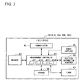
- the configuration of the field device 40 such as the transmitter 5, the differential pressure transmitter 6, the noise sensors 10a and 10b, and the vibration sensor 10c will be described with reference to FIG. 3 .
- FIG. 3 is a configuration diagram showing one example of schematic configuration of the field device 40 according to the present embodiment.
- the configuration of the field device 40 is not limited to the configuration shown in FIG. 3 .
- the field device 40 (the transmitter 5, the differential pressure transmitter 6, the noise sensors 10a and 10b, and the vibration sensor 10c) includes a communicator 41, a measure 42, a measurement controller 43, a storage 44, a power supplier 45, a position information acquirer 46, and a timer 47 (timer).
- the communicator 41 is configured to communicate with the measurement management apparatus 20 (external apparatus) connected to the communication network 7 using field bus communication or industrial wireless communication such as ISA100.11a.
- the measure 42 is configured to measure a measurement target.
- the measure 42 includes a sensor, which is adaptable to measurement specifications of each field device 40 (an acoustic sensor such as a microphone, a vibration sensor, a vibration-type pressure sensor, or the like).
- the measurement controller 43 is configured to acquire the measured results from the measure 42, generate measured data, which includes a process value such as a pressure value, sound volume, or the like, based on the acquired measured results, and transmit the generated measured data to the measurement management apparatus 20 via the communicator 41.
- the measurement controller 43 includes a measured result acquirer 431 configured to acquire measured results from the measure 42 and to generate measured data, and a measured data transmitter 432 configured to transmit the generated measured data via the communicator 41.
- the measurement controller 43 further includes a time synchronizer 433 and a measurement time controller 434.
- the time synchronizer 433 is configured to acquire common time information for time synchronization transmitted from the measurement management apparatus 20 via the communicator 41.
- the time synchronizer 433 is configured to adjust the time of the timer 47 based on the acquired time information. Thereby, the timer 47 is configured to time the time which is correlated with the time information acquired from the measurement management apparatus 20.
- the timer 47 may include another timer configured to time a period of time in addition to the timer configured to time a time.
- the timer 47 may be included outside the measurement controller 43 as shown in FIG. 3 , or included inside it. Based on the time or the period of time timed by the timer 47, the measurement controller 43 is configured to control the measurement timing and the operation time of each element included in the field device 40 so as to reduce the electrical power.
- the measurement time controller 434 is configured to acquire information related to the measurement time of the measure 42 transmitted from the measurement management apparatus 20 via the communicator 41. Based on the time timed by the timer 47 and the acquired measurement time, the measurement time controller 434 is configured to control the measure 42 so that the measure 42 performs measurements at the measurement time.
- the measurement time controller 434 After the measurement time controller 434 acquires the measurement start time from the measurement management apparatus 20 via the communicator 41, the measurement time controller 434 makes the timer 47 time a time, and makes the measure 42 perform measurements when reaching the measurement start time.
- the measured result acquirer 431 acquires the measured results from the measure 42, and stores the measured data based on the acquired measured results (instantaneous values of noise or vibration, waveform data of noise or vibration in a time domain or in a frequency domain, or the like) and information indicating the measurement time into the storage 44.
- the measured data transmitter 432 transmits the measured data to the measurement management apparatus 20 via the communicator 41.
- the measured data related to information indicating the measurement time, which corresponds to the measured data, may be transmitted.
- the measured data may include the position information acquired by the position information acquirer 46.
- the measurement controller 43 may continuously activate the measure 42, make the measure 42 perform measurements, and acquire the measured results only when reaching the measurement start time.
- the storage 44 includes a recoding medium such as a random access memory (RAM), an electrically erasable programmable read-only memory (EEPROM) a flash read-only memory (ROM), and a hard disk drive (HDD), or combination thereof.
- the storage 44 stores unique information of the sensor included in the measure 42, the measured data based on the measured results measured by the measure 42 (instantaneous values of noise or vibration, waveform data of noise or vibration in a time domain or in a frequency domain, or the like), or the like.
- the power supplier 45 is configured to be controlled by the measurement controller 43 and supply electrical power supplied from an external power source or electrical power supplied from a battery installed in the field device 40 to the communicator 41, the measure 42, the measurement controller 43, the storage 44, the power supplier 45, the position information acquirer 46, and the timer 47.
- the power supplier 45 may configured to supply the electrical power to each element included in the field device 40 via the measurement controller 43 or directly.
- the position information acquirer 46 includes, for example, a GPS receiving unit, and acquires the own position information based on electrical waves received from a GPS satellite.
- the position information acquirer 46 may be configured to calculate the own position information based on the position information supplied from the measurement management apparatus 20 via the communicator 41 and acquire it.
- FIG. 4 is a sequence diagram showing one example of measurement process with regard to measurements according to the present embodiment.
- the measurement management apparatus 20 acquires the measured data measured by each field device 40 at the same measurement time.
- the measurement management apparatus 20 periodically transmits common time information (for example, the same time information) used for time synchronization for network management to each field device 40 connected to the communication network 7 (step S101: time synchronization).
- Each field device 40 adjusts the time of the timer 47 based on the acquired time information. Thereby, each timer 47 included in the field device 40 times a time which is correlated with the time information acquired from the measurement management apparatus 20.
- the measurement management apparatus 20 transmits information indicating the measurement start time (information to instruct that measurements are performed at the measurement time) to each field device 40 connected to the communication network 7 (step S110: measurement start time transmission). For example, the measurement management apparatus 20 transmits information indicating the same measurement start time instructed by a user to each field device 40.
- each field device 40 acquires the information indicating the measurement start time
- each field device 40 transmits a response indicating the acquirement to the measurement management apparatus 20 (step S120: measurement start time acquirement response).
- each field device 40 When each field device 40 acquires the information indicating the measurement start time, each field device 40 starts the timing of the timer 47 and times a period of time required to reach the measurement start time based on the correlated time information in each field device 40 and the information indicating the measurement start time acquired in the step S120 (step S130).
- step S140 When the timing by the timer 47 is completed and the time reaches the measurement start time, in each field device 40, measurements by the measure 42 are started and the measured results are stored into the storage 44 (step S140).
- the measurement management apparatus 20 transmits information indicating a transmission request of measured data to each field device 40 after a predetermined period of time (step S150: measured data transmission request).
- the predetermined period of time is a period of time required to complete the measurement of each field device 40.
- each field device 40 acquires the information indicating the transmission request of the measured data from the measurement management apparatus 20
- each field device 40 transmits the measured data based on the measured results to the measurement management apparatus 20 (step S160: measured data transmission).
- the measurement management apparatus 20 acquires the measured data, which have been measured at the same measurement time as each other, from the field devices 40.
- the measurement management apparatus 20 may acquire measured data related to information indicating the measurement time from each field device 40.
- each field device 40 may divide the measured data and perform the transmission operation of the divided measured data in plural times (in other words, each field device 40 may perform the process in the step S160 in plural times). Then, the divided measured data may be integrated by the measurement management apparatus 20.
- the measurement management apparatus 20 may acquire measured data, which have been measured by field devices 40 at different measurement times from each other.
- the different measurement times may be different from each other by a predetermined period of time (delay time).
- the measurement management apparatus 20 may transmit, to each field device 40, information to instruct that each field devices 40 perform measurements at different measurement times from each other.
- the different measurement times may be different from each other by a predetermined period of time (delay time).
- the predetermined time difference (delay time) may be set in each field device 40.
- the measurement management apparatus 20 may transmit information indicating a criterial measurement time in the process of the step S110 shown in FIG. 4 , and acquire, from each field device 40, measured data, which has been measured at a measurement time obtained by adding the predetermined time difference (delay time) to the transmit measurement time.
- the field device 40 may start measurements when the time of the timer 47 matches the measurement start time without timing the period of time required to reach the measurement start time.
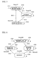
- FIG. 5 is a state transition diagram showing the operation states of the measurement management apparatus 20 according to the present embodiment.
- a State 101 indicates a "measurement start time input waiting" state.
- the measurement management apparatus 20 waits an input designating the measurement start time by a user operation.
- the measurement manager 25 included in the measurement management apparatus 20 periodically transmits common time information used for network management (for example, the same time information) to each field device 40 connected to the communication network 7 (refer to the step S101 shown in FIG. 4 ).
- the measurement manager 25 transmits the information indicating the measurement start time to each field device 40 (refer to the step S110 shown in FIG. 4 ) and receives the response, which indicates the acquirement of the information indicating the measurement start time (refer to the step S120 shown in FIG. 4 ), from each field device 40, and the state of the measurement management apparatus 20 is transited to a State 102 (step ST11).
- the State 102 indicates a "measurement completion waiting" state.
- the measurement management apparatus 20 waits the completion of the measurement of each field device 40.
- the measurement manager 25 transmits the information indication the transmission request of the measured data to each field device 40 after the time required to perform measurements in each field device 40 passes (refer to the step S150 shown in FIG. 4 ) and the state of the measurement management apparatus 20 is transited to a State 103 (step ST12).
- the State 103 indicates a "measured data receiving" state.
- the measurement management apparatus 20 receives the measured data from each field device 40 (refer to the step S160 shown in FIG. 4 ).
- the measurement manager 25 completes the receiving of the measured data and acquires the measured data
- the measurement manager 25 supplies the acquired measured data to at least one of the estimator 26, the distribution information generator 27, the device manager 28, and the operation history manager 29 and the state of the measurement management apparatus 20 is transited to the "measurement start time input waiting" state of the State 101 (step ST13).
- the measurement management apparatus 20 integrates the divided measured data and supplies the integrated measured data to at least one of the estimator 26, the distribution information generator 27, the device manager 28, and the operation history manager 29.
- the measurement manager 25 monitors the presence or absence of the input designating the measurement start time input and the state of the State 101 is continued (step ST 14).
- the measurement manager 25 monitors the passing of the measurement time in each field device 40 and the state of the State 102 is continued (step ST15).
- the measurement manager 25 continues the receiving of the measured data and the state of the State 103 is continued (step ST16).
- the measurement management apparatus 20 When the state of the measurement management apparatus 20 is transited from the power-off state to the power-on state (or when the measurement management apparatus 20 is restarted), the measurement management apparatus 20 starts each elements in the device and the state is transited to the "measurement start time input waiting" state of the State 101 (step ST 17).
- FIG. 6 is a state transition diagram showing the operation states of the field device 40 according to the present embodiment.
- a State 201 indicates a "measurement start time designation waiting" state.
- the field device 40 waits the designation of the measurement start time from the measurement management apparatus 20.
- the measurement controller 43 included in the field device 40 periodically acquire the time information for time synchronization transmitted from the measurement management apparatus 20 (refer to the step S101 shown in FIG. 4 ), and adjusts the time of the timer 47 based on the acquired time information.
- the measurement controller 43 When the measurement controller 43 acquires the information indicating the measurement start time transmitted from the measurement management apparatus 20 in the State 201 (refer to the step S110 shown in FIG. 4 ), the measurement controller 43 transmits the response indicating the acquirement to the measurement management apparatus 20 (refer to the step S120 shown in FIG. 4 ) and starts the timing of the timer 47 (refer to the step S130 shown in FIG. 4 ), and the state of the field device 40 is transited to a State 202 (step ST20).
- the State 202 indicates a "measurement start time waiting" state.
- the field device 40 waits to reach the measurement start time (in other words, the designated measurement start time) indicated by the information indicating the measurement start time, which has been transmitted from the measurement management apparatus 20.
- the measurement controller 43 starts the measurements of the measure 42, and the state of the field device 40 is transited to a State 203 (step ST21).
- the State 203 indicates a "measuring" state.
- the field device 40 performs measurements.
- the measurement controller 43 makes the measure 42 perform the measurements and stores the measured results measured by the measure 42 into the storage 44.
- the measurement controller 43 acquires the information indicating the transmission request of the measured data from the measurement management apparatus 20 (refer to the step S150 shown in FIG. 4 )
- the measurement controller 43 starts the transmission of the measured data based on the measured results (refer to the step S160 shown in FIG. 4 ), and the state of the field device 40 is transited to a State 204 (step ST22).
- the State 204 indicates a "measured data transmission" state.
- the field device 40 transmits the measured data to the measurement management apparatus 20.
- the measurement controller 43 clears the timer 47 and the state of the field device 40 is transited to the State 201 (step ST23).
- the measurement controller 43 monitors the presence or absence of the acquirement of the information indicating the measurement start time and the state of the State 201 is continued (step ST24).
- the measurement controller 43 waits without starting the measurements until the timing of the timer 47 is completed and the state of the State 202 is continued (step ST25).
- the measurement controller 43 continues the measurements by the measure 42 and the state of the State 203 is continued (step ST26).
- the measurement controller 43 When the transmission of the measured data is not completed and the transmission is performed in the "measured data transmission" state of the State 204, the measurement controller 43 continues the transmission of the measured data and the state of the State 204 is continued (step ST27). If the measured data is large in size and cannot be transmitted data at one time, the measurement controller 43 divides the measured data and performs the transmission operation of the divided measured data in plural times.
- the field device 40 starts each elements in the device and the state is transited to the "measurement start time designation waiting" state of the State 201 (step ST28).
- the estimator 26 included in the measurement management apparatus 20 estimates an abnormality and the site of the abnormality occurrence (specific matters) in the plant, which is the measurement target of the measurement system 100, based on the measured data in which the measurement times are correlated with each other.
- the measured data is acquired from each of the plurality of field devices 40.
- the estimator 26 estimates the abnormality and the site of the abnormality occurrence by correlating the measured data in which the measurement times are correlated with each other.
- the measured data is acquired from each of the plurality of field devices 40.
- a cross-correlation function for calculating a correlation coefficient C which represents the correlation between p5(t) and p6(t) is represented by the following equation 1.
- C ⁇ 1 ⁇ p 5 t ⁇ p ⁇ 6 ⁇ t + ⁇ 1 ⁇ d t t : Time ⁇ 1 : Delay time
- the measurement management apparatus 20 designates a time "T1" (first time) as the measurement start time with respect to the transmitter 5 and designates a time “T1+ ⁇ 1 " (second time) as the measurement start time with respect to the differential pressure transmitter 6. In this case, when the correlation coefficient C, which is calculated by the equation 1 based on the measured data acquired from the transmitter 5 and the differential pressure transmitter 6, is maximized, this indicates that there is no abnormality between the transmitter 5 and the differential pressure transmitter 6.
- the measurement management apparatus 20 can acquire a data string of the line pressure signal at the respective sites.
- the estimator 26 uses the acquired data string for the calculation of the correlation coefficient C.
- the specific matters can be estimated that some abnormality between the transmitter 5 and the differential pressure transmitter 6 is occurring, for example, the turbulence of the fluid flow in the line 1 is occurring due to corrosion or failure of the line 1.
- the delay time ⁇ 1 is nearly equal to 0.1 sec bases on the equation 2.
- the time synchronization accuracy for network management of field bus communication or industrial wireless communication such as ISA100.11 a is nearly equal to 0.001 sec.
- the delay time ⁇ 1 has a value which can be designated in the measurement system 100 according to the present embodiment.
- the above-described equation 1 and equation 2 are also adaptable by setting the information as "v". For example, an abnormality such as corrosion or failure of the line 1 and the site of the abnormality occurrence are estimatable.
- each noise sensor 10a and 10b has a microphone or the like
- the distance between the installation position of the noise sensor 10a and the installation position of the noise sensor 10b is defined as d
- the sound source direction is defined as ⁇
- the sound velocity is defined as c.
- a cross-correlation function for culculating a correlation coefficient Cs which represents the correlation between p10a(t) and p10b(t) is represented by the following equation 4.
- C s ⁇ 1 ⁇ p 10 ⁇ a t ⁇ p ⁇ 10 ⁇ b ⁇ t + ⁇ 1 ⁇ d t t : Time ⁇ 1 : Delay time
- the arrival time difference ⁇ T is obtained using a time when the correlation coefficient Cs is maximized.
- the measurement management apparatus 20 designates a plurality of pairs of the measurement start time and the delay time ⁇ 1 to the noise sensors 10a and 10b, and the estimator 26 performs the calculation of the equation (4) based on the measured data measured at each designated pair of the measurement start time and the delay time ⁇ 1 .
- the delay time ⁇ 1 at the maximum of the correlation coefficient Cs can be gradationally obtained.
- the estimator 26 can estimate the sound source direction ⁇ based on the above-described equation 3 using the delay time ⁇ 1 at the maximum of the correlation coefficient Cs as the arrival time difference ⁇ T.
- the measurement system 100 includes the plurality of field devices 40 (an example of measurement device), each of which is configured to perform measurements at each of a plurality of sites in a measurement target, and the measurement management apparatus 20 configured to acquire measured data measured by each of the plurality of field devices 40 via the communication network 7.
- the times are correlated with each other, and each field devices 40 is configured to transmit measured data measured based on the correlated time.
- the measurement management apparatus 20 includes the measured data acquirer 253 configured to acquire measured data from each field devices 40.
- the measurement management apparatus 20 further includes the synchronization time transmitter 251 configured to transmit common time information to each of the plurality of field devices 40.
- Each of the plurality of field devices 40 includes the timer 47 (timer) configured to time the time correlated with the time information transmitted from the synchronization time transmitter 251.
- the measurement system 100 uses time information to be transmitted to the plurality of field devices 40, which are connected to the communication network 7 for field bus communication or industrial wireless communication such as ISA100.11a, to perform a communication synchronization.
- the measurement system 100 can correlate measurement times of the plurality of field devices 40, which are positioned at a plurality of sites in a plant, with each other. Since the measurement system 100 (measurement management apparatus 20) can acquire, from the field devices 40, measured data where the measurement time are correlated with each other, the measurement system 100 can correlate these measured data. Therefore, the measurement system 100 (measurement management apparatus 20) can acquire effectively usable measured data from each of the plurality of field devices 40.
- the measurement management apparatus 20 may include the estimator 26 configured to estimate specific matters of a measurement target (an abnormality and the site of the abnormality occurrence) based on a plurality of measured data acquired by the measured data acquirer 253.
- the measurement system 100 (measurement management apparatus 20) can estimate an abnormality and the site of the abnormality occurrence by correlating the measured data acquired from the field devices 40. Therefore, the measurement system 100 (measurement management apparatus 20) according to the present embodiment can easily estimate an abnormality and the site of the abnormality occurrence in a measurement target (for example, in a plant).
- the measurement management apparatus 20 further includes the measurement time indicator 252 configured to transmit, to each of the plurality of field devices 40, information related to a measurement time (for example, a measurement start time) when each field device 40 performs measurements.
- the measured data acquirer 253 is configured to acquire, from each of the plurality of field devices 40, measured data measured by each field device 40 based on the measurement time, which is indicated by the information related to the measurement time transmitted from the measurement time indicator 252.
- the measurement system 100 (measurement management apparatus 20) can designate the measurement time of each of the plurality of field devices 40. Therefore, the measurement management apparatus 20 can acquire the measured data measured at a correlated arbitrary measurement time from each of the plurality field devices 40.
- the measurement time indicator 252 may transmit, to each of the plurality of field devices 40, information, which instructs that each field device 40 performs the measurements at the same measurement time, as the information related to the measurement time.
- the measurement time indicator 252 may transmit, to each of the plurality of field devices 40, information, which instructs that each field device 40 performs the measurements at different measurement times from each other, as the information related to the measurement time.
- the different measurement times may be different from each other by a predetermined period of time.
- the measurement system 100 (measurement management apparatus 20) enables each of the plurality of field devices 40 to perform the measurements at the same time or to perform the measurements at different measurement times.
- the different measurement times may be different from each other by a constant delay time.
- each of the plurality of field devices 40 is subjected to the periodical time-synchronization via the communication network 7 and the field devices 40 perform measurements at the same time or at the delayed time by a designated period of time based on the designated measurement time. Therefore, the measurement system 100 can correlate the measured data.
- the estimator 26 may estimate specific matters of measurement target (an abnormality and the site of the abnormality occurrence) based on the correlation between a plurality of measured data acquired by the measured data acquirer 253.
- the estimator 26 included in the measurement management apparatus 20 may estimate specific matters of measurement target (an abnormality and the site of the abnormality occurrence) based on at least a plurality of measured data measured at the same measurement time among a plurality of measured data acquired by the measured data acquirer 253. In other cases, the estimator 26 may estimate specific matters of measurement target (an abnormality and the site of the abnormality occurrence) based on at least a plurality of measured data measured at different measurement times from each other among a plurality of measured data acquired by the measured data acquirer 253. The different measurement times may be different from each other by a predetermined period of time.
- the estimator 26 may estimate specific matters of measurement target (an abnormality and the site of the abnormality occurrence) based on at least first measured data measured at a first time (for example, the time "T1" described in the above-described “First example of Method for estimating specific matters") and second measured data measured at a second time, which is delayed from the first time by a predetermined period of time, (for example, the time "T1+ ⁇ 1 " described in the above-described "First example of Method for estimating specific matters") among a plurality of measured data acquired by the measured data acquirer 253.
- first measured data measured at a first time for example, the time "T1" described in the above-described “First example of Method for estimating specific matters
- second measured data measured at a second time which is delayed from the first time by a predetermined period of time, (for example, the time "T1+ ⁇ 1 " described in the above-described "First example of Method for estimating specific matters") among a plurality of measured data acquired by the measured data acquirer 253.
- the measurement system 100 (measurement management apparatus 20) can easily estimate an abnormality such as corrosion and failures of the line 1, the site of the abnormality occurrence, a direction of a noise source, or the like by correlating the measured data measured by the plurality of the field devices 40 at the same time or correlating the measured data measured by the plurality of the field devices 40 at different measurement times from each other.
- the different measurement times may be different from each other by a constant period of time (delay time).
- the example where the measurement management apparatus 20 designates the measurement time to each of the plurality of the field devices 40 designates the measurement time to each of the plurality of the field devices 40.
- the present invention is not limited to this example.
- the same measurement time as each other or the different measurement times from each other is previously set in each of the plurality of the field devices 40 and the measurements may be performed at the set measurement time.
- the different measurement times may be different from each other by a predetermined period of time.
- the measurement management apparatus 20 may estimate an abnormality or the site of the abnormality occurrence based on a plurality of measured data (measured data measured at the same measurement time, or measured data measured at different measurement times from each other in which the different measurement times are different from each other by a predetermined period of time) acquired by acquiring measured data related to information indicating a measurement time from each of the plurality of field devices 40.
- the field devices 40 includes the measure 42 configured to measure a measurement target, the timer 47 (an example of timer) configured to time a time correlated with time information acquired from an external apparatus (for example, the measurement management apparatus 20), the measurement controller 43 configured to control the measure 42 to perform measurements when the time timed by the timer 47 reaches a predetermined measurement time, and the measured data transmitter 432 configured to transmit the measured data measured by the measure 42 to an external apparatus (for example, the measurement management apparatus 20) communicatively connected to the field devices 40 via the communication network 7.
- the predetermined measurement time may be a measurement time designated as a time when the field device 40 performs measurements and transmitted from the measurement management apparatus 20.
- the predetermined measurement time may correspond to the same measurement time or the different measurement times from each other previously set in each of the plurality of field devices 40. The different measurement times may be different from each other by a predetermined period of time.
- one field device 40 can transmit measured data measured at a measurement time correlated with that of another field device 40 to the measurement management apparatus 20. Therefore, the measurement system 100 can easily estimate an abnormality of a measurement target and the site of the abnormality occurrence based on measured data in which the measurement times are correlated with each other. The measured data is acquired from each of the plurality of field devices 40.
- the field device 40 may be a measurement device connected to the measurement management apparatus 20 via the communication network 7, and the timer 47 may time a time correlated with time information acquired from the measurement management apparatus 20.
- the measurement controller 43 may acquire, from the measurement management apparatus 20, information related to a measurement time when the measurement 42 performs measurements and control the measurement 42 to perform measurements at the measurement time based on the time timed by the timer 47 and the acquired information related to the measurement time.
- the measured data transmitter 432 may transmit the measured data measured by the measure 42 to the measurement management apparatus 20 communicatively connected to the measured data transmitter 432 via the communication network 7.
- the field device 40 can be time-synchronized with respect to the time information, which is transmitted from the measurement management apparatus 20 connected to the communication network 7 for field bus communication or industrial wireless communication such as ISA100.11a so as to perform communication synchronization.
- the field device 40 can perform measurements at the measurement time designated by the measurement management apparatus 20 and transmit the measured data to the measurement management apparatus 20. Therefore, the measurement system 100 can easily estimate an abnormality of measurement target and the site of the abnormality occurrence based on the measured data in which the measurement times are correlated with each other. The measured data is acquired from each of the plurality of field devices 40.
- the measurement process for acquiring, from each field device 40, measured data in which the measurement times are correlated with each other described in the above embodiment may be continuously performed or be performed only in an abnormal state where an abnormality is occurring.
- the measurement system 100 may simply determine whether an abnormality is occurring or not based on measured data asynchronously measured by each field device 40 in a normal state in which an abnormality is not occurring (somewhat less-accurate simple determination) and may acquire measured data in which the measurement times are correlated with each other from each field device 40 in an abnormal state in which an abnormality is occurring and accurately estimate an abnormality or the site of the abnormality occurrence (accurate determination (estimation)).
- the measurement management apparatus 20 transmits time information for time-synchronization to each of the plurality of field devices 40 and each field device 40 performs time-synchronization based on the time information.
- the measurement management apparatus 20 and each of the plurality of field devices 40 may include an NTP server configured to be supplied with time information via an internet, a GPS receiving unit configured to acquire time information based on electrical waves received from a GPS satellite, or the like and may time the same time based on the supplied time information or the received time information.
- the time information used for the time-synchronization is not limited to the time information supplied to the NTP server and the time information received from the GPS satellite and may be other time information.
- time information received from a wireless station configured to transmit standard waves, time information superimposed on airwaves for television or radio, time information superimposed on control signals transmitted from a mobile phone base station, or the like may be used for time-synchronization.
- a part of or all of functions of each element included in the measurement management apparatus 20 according to the above-described embodiment or a part of or all of functions of each element included in the field device 40 may be implemented by a computer.
- the above-described functions may be implemented by recording a program for implementing the above-described functions into a computer readable storage medium, making a computer system read the program stored in the storage medium, and executing the program.
- the "computer system” may be embedded in the measurement management apparatus 20 or the field device 40 and include an operating system and a hardware such as a peripheral device.
- the "computer system” may include an environment for providing homepage (or display environment).
- the "computer readable storage medium” indicates a portable medium such as a flexible disk, a magnetic optical disk, a read-only memory (ROM), a CD-ROM and a storage device such as a hard-disk embedded in a computer system.
- the "computer readable storage medium” may include a medium for dynamically storing a program in a short time like a communication wire used to transmit a program via a communication line such as a network including the Internet and a phone line and a medium for storing a program for a given length of time like a volatile memory embedded in a computer system, which is a server or client in that case.
- the above-described program may be used to implement a part of the above-described functions and may implement the above-described functions in cooperation with another program previously stored in the computer system.
- the measurement management apparatus 20 or a part of or all of the field devices 40 may be implemented as a integrated circuit such as a large-scale integration (LSI).
- LSI large-scale integration
- each function block of the measurement management apparatus 20 or the field device 40 may be implemented by its own processor.
- a part of or all of function blocks of the measurement management apparatus 20 or the field device 40 may be integrated and implemented by a processor.
- the method for integrating a circuit is not limited to LSI and may be implemented by a dedicated communication circuit or a general-purpose processor. When a technique for integrating a circuit as a substitute for LSI appears with the development of semiconductor technology, the integrated circuit based on this technique may be adopted.
Landscapes
- Physics & Mathematics (AREA)
- General Physics & Mathematics (AREA)
- Engineering & Computer Science (AREA)
- Automation & Control Theory (AREA)
- General Engineering & Computer Science (AREA)
- Manufacturing & Machinery (AREA)
- Quality & Reliability (AREA)
- Arrangements For Transmission Of Measured Signals (AREA)
- Testing And Monitoring For Control Systems (AREA)
Applications Claiming Priority (1)
| Application Number | Priority Date | Filing Date | Title |
|---|---|---|---|
| JP2014037157A JP6403957B2 (ja) | 2014-02-27 | 2014-02-27 | 測定システム、測定管理装置、測定機器、および測定方法 |
Publications (2)
| Publication Number | Publication Date |
|---|---|
| EP2913640A1 true EP2913640A1 (de) | 2015-09-02 |
| EP2913640B1 EP2913640B1 (de) | 2018-10-31 |
Family
ID=52633063
Family Applications (1)
| Application Number | Title | Priority Date | Filing Date |
|---|---|---|---|
| EP15155769.1A Active EP2913640B1 (de) | 2014-02-27 | 2015-02-19 | Messsystem, Messverwaltungsvorrichtung, Messvorrichtung und Messverfahren |
Country Status (5)
| Country | Link |
|---|---|
| US (1) | US10359766B2 (de) |
| EP (1) | EP2913640B1 (de) |
| JP (1) | JP6403957B2 (de) |
| CN (1) | CN104880221B (de) |
| DK (1) | DK2913640T3 (de) |
Families Citing this family (28)
| Publication number | Priority date | Publication date | Assignee | Title |
|---|---|---|---|---|
| US11120371B2 (en) * | 2014-06-23 | 2021-09-14 | Sensia Netherlands B.V. | Systems and methods for cloud-based asset management and analysis regarding well devices |
| US20170122092A1 (en) | 2015-11-04 | 2017-05-04 | Schlumberger Technology Corporation | Characterizing responses in a drilling system |
| JP2017220081A (ja) * | 2016-06-09 | 2017-12-14 | 富士電機株式会社 | センサ装置、センサシステムおよび測定方法 |
| US10024823B2 (en) | 2016-07-11 | 2018-07-17 | General Electric Company | Evaluating condition of components using acoustic sensor in lighting device |
| JP6487386B2 (ja) | 2016-07-22 | 2019-03-20 | ファナック株式会社 | 時刻精度を維持するためのサーバ、方法、プログラム、記録媒体、及びシステム |
| US10782679B2 (en) | 2016-12-15 | 2020-09-22 | Schlumberger Technology Corporation | Relationship tagging of data in well construction |
| JP6969108B2 (ja) * | 2017-02-20 | 2021-11-24 | 横河電機株式会社 | フィールド機器および情報提供方法 |
| US11143010B2 (en) | 2017-06-13 | 2021-10-12 | Schlumberger Technology Corporation | Well construction communication and control |
| US11021944B2 (en) | 2017-06-13 | 2021-06-01 | Schlumberger Technology Corporation | Well construction communication and control |
| US11422999B2 (en) | 2017-07-17 | 2022-08-23 | Schlumberger Technology Corporation | System and method for using data with operation context |
| DE102017116167A1 (de) * | 2017-07-18 | 2019-01-24 | Endress+Hauser Process Solutions Ag | Verfahren zum Überwachen einer Automatisierungsanlage |
| JP2019030595A (ja) * | 2017-08-09 | 2019-02-28 | オムロンヘルスケア株式会社 | 測定装置、送信方法およびプログラム |
| JP6919596B2 (ja) * | 2018-03-01 | 2021-08-18 | オムロン株式会社 | 計測システムおよび方法 |
| IT201800005091A1 (it) * | 2018-05-04 | 2019-11-04 | "Procedimento per monitorare lo stato di funzionamento di una stazione di lavorazione, relativo sistema di monitoraggio e prodotto informatico" | |
| JP2019200067A (ja) * | 2018-05-14 | 2019-11-21 | 横河電機株式会社 | 測定システム、測定方法及び圧力測定装置 |
| US12366152B2 (en) | 2018-06-04 | 2025-07-22 | Schlumberger Technology Corporation | Well construction workstation and control |
| DE102018211099B4 (de) * | 2018-07-05 | 2020-06-18 | Carl Zeiss Smt Gmbh | Verfahren und Vorrichtung zum Bewerten eines statistisch verteilten Messwertes beim Untersuchen eines Elements eines Photolithographieprozesses |
| WO2020044518A1 (ja) * | 2018-08-30 | 2020-03-05 | 中国電力株式会社 | 同期システム、測定同期システム、同期方法、プログラム |
| US10909847B1 (en) * | 2018-09-19 | 2021-02-02 | All Turtles Corporation | Building urban area noise pollution maps and mitigating noise from emergency vehicles |
| US10907466B2 (en) | 2018-12-07 | 2021-02-02 | Schlumberger Technology Corporation | Zone management system and equipment interlocks |
| US10890060B2 (en) | 2018-12-07 | 2021-01-12 | Schlumberger Technology Corporation | Zone management system and equipment interlocks |
| CN110412382B (zh) * | 2019-08-07 | 2021-07-20 | 中核控制系统工程有限公司 | 一种基于图像处理的s-vdu响应时间自动测量装置 |
| US11514383B2 (en) | 2019-09-13 | 2022-11-29 | Schlumberger Technology Corporation | Method and system for integrated well construction |
| US12055027B2 (en) | 2020-03-06 | 2024-08-06 | Schlumberger Technology Corporation | Automating well construction operations based on detected abnormal events |
| US11933156B2 (en) | 2020-04-28 | 2024-03-19 | Schlumberger Technology Corporation | Controller augmenting existing control system |
| JP7417732B2 (ja) * | 2020-06-15 | 2024-01-18 | 株式会社日立製作所 | 自動点検システム及び無線子機 |
| KR102459094B1 (ko) * | 2021-02-02 | 2022-10-26 | 주식회사 하이드로넷 | 지하수 이용량 원격 검침 및 관리 시스템 |
| US20250216845A1 (en) * | 2023-12-28 | 2025-07-03 | Endress+Hauser Inc. | Industrial process automation system with field device level anomaly detection |
Citations (5)
| Publication number | Priority date | Publication date | Assignee | Title |
|---|---|---|---|---|
| US20030158682A1 (en) * | 2002-02-18 | 2003-08-21 | Yokogawa Electric Corporation | Measured data synchronizing system and measured data synchronizing method |
| US20040167745A1 (en) * | 2003-02-25 | 2004-08-26 | Yokogawa Electric Corporation | Measured data synchronization system |
| JP2005037247A (ja) | 2003-07-15 | 2005-02-10 | Yokogawa Electric Corp | 時間記録機能付き物理量測定器 |
| US20130018620A1 (en) * | 2010-03-24 | 2013-01-17 | Sylvain Riendeau | Method And System For Time Synchronization Of Phase Of Signals From Respective Measurement Devices |
| JP2014037157A (ja) | 2012-08-10 | 2014-02-27 | Sumitomo Rubber Ind Ltd | 空気入りタイヤ |
Family Cites Families (17)
| Publication number | Priority date | Publication date | Assignee | Title |
|---|---|---|---|---|
| JP2750956B2 (ja) * | 1991-02-22 | 1998-05-18 | 日工株式会社 | アナログ多重伝送方法 |
| US5304800A (en) * | 1992-11-10 | 1994-04-19 | Nalco Chemical Company | Leak detection and responsive treatment in industrial water processes |
| JPH06311151A (ja) * | 1993-04-26 | 1994-11-04 | Fujitsu Ltd | 絶対時刻同期制御装置 |
| JP3883025B2 (ja) * | 1998-03-26 | 2007-02-21 | ヤマハマリン株式会社 | 筒内燃料噴射式エンジン |
| US7007545B1 (en) * | 1999-10-26 | 2006-03-07 | Peter Martinek | Method and measurement probe for the performance of measurements in water supply systems |
| US6567006B1 (en) * | 1999-11-19 | 2003-05-20 | Flow Metrix, Inc. | Monitoring vibrations in a pipeline network |
| JP3846330B2 (ja) * | 2002-02-21 | 2006-11-15 | 富士電機システムズ株式会社 | 収集データの同期化方法及びデータ処理システム |
| CA2570029A1 (en) * | 2004-06-09 | 2005-12-22 | International Business Machines Corporation | Distance measurement system, distance measurement method, information processing apparatus, program and recording medium |
| JP4257305B2 (ja) * | 2005-03-04 | 2009-04-22 | 株式会社東芝 | 遠隔振動監視装置 |
| CN100575967C (zh) * | 2007-09-20 | 2009-12-30 | 上海交通大学 | 交流点焊动态电阻实时测量装置与方法 |
| US8866453B2 (en) * | 2008-08-28 | 2014-10-21 | Intersil Americas LLC | Switching regulator input current sensing circuit, system, and method |
| JP2010061777A (ja) * | 2008-09-08 | 2010-03-18 | Yokogawa Electric Corp | メモリテスト装置 |
| JP2013228245A (ja) * | 2012-04-25 | 2013-11-07 | Toshiba Corp | 振動測定システムおよび振動測定方法 |
| CN102680893A (zh) * | 2012-05-22 | 2012-09-19 | 李朝晖 | 发电机主绝缘故障实时在线预警装置及预警方法 |
| JP5549710B2 (ja) * | 2012-07-04 | 2014-07-16 | 横河電機株式会社 | 無線通信システム及び情報提供方法 |
| JP6295955B2 (ja) * | 2012-09-28 | 2018-03-20 | 日本電気株式会社 | 漏洩位置特定装置、漏洩位置特定方法、漏洩位置特定プログラム、及び漏洩位置特定システム |
| HK1217363A1 (zh) * | 2013-01-28 | 2017-01-06 | Aquarius Spectrum Ltd. | 用於检测管线网络中的泄漏的方法及设备 |
-
2014
- 2014-02-27 JP JP2014037157A patent/JP6403957B2/ja active Active
-
2015
- 2015-02-19 EP EP15155769.1A patent/EP2913640B1/de active Active
- 2015-02-19 DK DK15155769.1T patent/DK2913640T3/en active
- 2015-02-20 US US14/626,962 patent/US10359766B2/en active Active
- 2015-02-25 CN CN201510087940.3A patent/CN104880221B/zh active Active
Patent Citations (5)
| Publication number | Priority date | Publication date | Assignee | Title |
|---|---|---|---|---|
| US20030158682A1 (en) * | 2002-02-18 | 2003-08-21 | Yokogawa Electric Corporation | Measured data synchronizing system and measured data synchronizing method |
| US20040167745A1 (en) * | 2003-02-25 | 2004-08-26 | Yokogawa Electric Corporation | Measured data synchronization system |
| JP2005037247A (ja) | 2003-07-15 | 2005-02-10 | Yokogawa Electric Corp | 時間記録機能付き物理量測定器 |
| US20130018620A1 (en) * | 2010-03-24 | 2013-01-17 | Sylvain Riendeau | Method And System For Time Synchronization Of Phase Of Signals From Respective Measurement Devices |
| JP2014037157A (ja) | 2012-08-10 | 2014-02-27 | Sumitomo Rubber Ind Ltd | 空気入りタイヤ |
Also Published As
| Publication number | Publication date |
|---|---|
| CN104880221A (zh) | 2015-09-02 |
| DK2913640T3 (en) | 2019-02-25 |
| US20150241871A1 (en) | 2015-08-27 |
| JP2015162108A (ja) | 2015-09-07 |
| JP6403957B2 (ja) | 2018-10-10 |
| EP2913640B1 (de) | 2018-10-31 |
| US10359766B2 (en) | 2019-07-23 |
| CN104880221B (zh) | 2017-08-29 |
Similar Documents
| Publication | Publication Date | Title |
|---|---|---|
| EP2913640B1 (de) | Messsystem, Messverwaltungsvorrichtung, Messvorrichtung und Messverfahren | |
| US10527515B2 (en) | Ultrasonic flow meter leak detection system and method | |
| US11274797B1 (en) | System and method for determining range of possible locations of pipeline leak | |
| JP6434419B2 (ja) | 流体搬送導管網をモニタリングするための装置、方法およびシステム | |
| US11153386B2 (en) | Data collection device, data collection system, data server, data collection method, and non-transitory computer readable storage medium | |
| US20150052979A1 (en) | Leakage signal analysis method | |
| US20180292292A1 (en) | Pipe condition detection device, pipe condition detection method, computer-readable recording medium, and pipe condition detection system | |
| JP6840066B2 (ja) | 漏水検知システムおよび漏水検知方法 | |
| JPWO2014050923A1 (ja) | 漏洩判定方法、漏洩判定システム、及びプログラム | |
| US7219553B1 (en) | Dynamic transient pressure detection system | |
| JPWO2017163954A1 (ja) | センサユニット、サーバ、システム、および、制御方法 | |
| US20210116323A1 (en) | Leakage inspection device, leakage inspection method, and storage medium | |
| JP6967502B2 (ja) | 漏水検知方法、漏水検知システム、及び、それに用いるセンサ端末 | |
| EP4163587B1 (de) | Abschätzvorrichtung, abschätzverfahren und abschätzcomputerprogramm zur abschätzung einer ablagerungsdicke | |
| Christos et al. | Autonomous low-cost wireless sensor platform for leakage detection in oil and gas pipes | |
| KR101780123B1 (ko) | 위성항법시스템에 의한 지진 감시 장치 및 방법 | |
| CN118168619A (zh) | 管内流体流量测量方法及装置、电子设备、存储介质 | |
| JP7095743B2 (ja) | 流体漏洩診断装置、流体漏洩診断システム、流体漏洩診断方法、及び、流体漏洩診断プログラム | |
| EP3591364A1 (de) | Messzeitspezifikationsvorrichtung, abtastvorrichtung, messzeitspezifikationsverfahren und computerlesbares aufzeichnungsmedium | |
| Horsburgh et al. | High frequency sea level recording for tsunami warning and enhanced storm surge monitoring at UK sites | |
| JP2008129754A (ja) | プロセスデータ記録装置およびプロセスデータ記録方法 | |
| JP2023132383A (ja) | ガスメータ及び地震判定方法 | |
| JP2025006025A (ja) | 漏洩位置推定装置及び漏洩位置推定方法 | |
| RU132552U1 (ru) | Дистанционный обнаружитель течи водопроводных сетей |
Legal Events
| Date | Code | Title | Description |
|---|---|---|---|
| PUAI | Public reference made under article 153(3) epc to a published international application that has entered the european phase |
Free format text: ORIGINAL CODE: 0009012 |
|
| AK | Designated contracting states |
Kind code of ref document: A1 Designated state(s): AL AT BE BG CH CY CZ DE DK EE ES FI FR GB GR HR HU IE IS IT LI LT LU LV MC MK MT NL NO PL PT RO RS SE SI SK SM TR |
|
| AX | Request for extension of the european patent |
Extension state: BA ME |
|
| 17P | Request for examination filed |
Effective date: 20160229 |
|
| RBV | Designated contracting states (corrected) |
Designated state(s): AL AT BE BG CH CY CZ DE DK EE ES FI FR GB GR HR HU IE IS IT LI LT LU LV MC MK MT NL NO PL PT RO RS SE SI SK SM TR |
|
| STAA | Information on the status of an ep patent application or granted ep patent |
Free format text: STATUS: EXAMINATION IS IN PROGRESS |
|
| 17Q | First examination report despatched |
Effective date: 20170313 |
|
| GRAP | Despatch of communication of intention to grant a patent |
Free format text: ORIGINAL CODE: EPIDOSNIGR1 |
|
| STAA | Information on the status of an ep patent application or granted ep patent |
Free format text: STATUS: GRANT OF PATENT IS INTENDED |
|
| INTG | Intention to grant announced |
Effective date: 20180531 |
|
| GRAS | Grant fee paid |
Free format text: ORIGINAL CODE: EPIDOSNIGR3 |
|
| GRAA | (expected) grant |
Free format text: ORIGINAL CODE: 0009210 |
|
| STAA | Information on the status of an ep patent application or granted ep patent |
Free format text: STATUS: THE PATENT HAS BEEN GRANTED |
|
| AK | Designated contracting states |
Kind code of ref document: B1 Designated state(s): AL AT BE BG CH CY CZ DE DK EE ES FI FR GB GR HR HU IE IS IT LI LT LU LV MC MK MT NL NO PL PT RO RS SE SI SK SM TR |
|
| REG | Reference to a national code |
Ref country code: CH Ref legal event code: EP Ref country code: GB Ref legal event code: FG4D |
|
| REG | Reference to a national code |
Ref country code: AT Ref legal event code: REF Ref document number: 1059939 Country of ref document: AT Kind code of ref document: T Effective date: 20181115 |
|
| REG | Reference to a national code |
Ref country code: IE Ref legal event code: FG4D |
|
| REG | Reference to a national code |
Ref country code: DE Ref legal event code: R096 Ref document number: 602015018944 Country of ref document: DE |
|
| REG | Reference to a national code |
Ref country code: NO Ref legal event code: T2 Effective date: 20181031 |
|
| REG | Reference to a national code |
Ref country code: DK Ref legal event code: T3 Effective date: 20190218 |
|
| REG | Reference to a national code |
Ref country code: NL Ref legal event code: MP Effective date: 20181031 |
|
| REG | Reference to a national code |
Ref country code: LT Ref legal event code: MG4D |
|
| REG | Reference to a national code |
Ref country code: AT Ref legal event code: MK05 Ref document number: 1059939 Country of ref document: AT Kind code of ref document: T Effective date: 20181031 |
|
| PG25 | Lapsed in a contracting state [announced via postgrant information from national office to epo] |
Ref country code: HR Free format text: LAPSE BECAUSE OF FAILURE TO SUBMIT A TRANSLATION OF THE DESCRIPTION OR TO PAY THE FEE WITHIN THE PRESCRIBED TIME-LIMIT Effective date: 20181031 Ref country code: AT Free format text: LAPSE BECAUSE OF FAILURE TO SUBMIT A TRANSLATION OF THE DESCRIPTION OR TO PAY THE FEE WITHIN THE PRESCRIBED TIME-LIMIT Effective date: 20181031 Ref country code: PL Free format text: LAPSE BECAUSE OF FAILURE TO SUBMIT A TRANSLATION OF THE DESCRIPTION OR TO PAY THE FEE WITHIN THE PRESCRIBED TIME-LIMIT Effective date: 20181031 Ref country code: LV Free format text: LAPSE BECAUSE OF FAILURE TO SUBMIT A TRANSLATION OF THE DESCRIPTION OR TO PAY THE FEE WITHIN THE PRESCRIBED TIME-LIMIT Effective date: 20181031 Ref country code: ES Free format text: LAPSE BECAUSE OF FAILURE TO SUBMIT A TRANSLATION OF THE DESCRIPTION OR TO PAY THE FEE WITHIN THE PRESCRIBED TIME-LIMIT Effective date: 20181031 Ref country code: BG Free format text: LAPSE BECAUSE OF FAILURE TO SUBMIT A TRANSLATION OF THE DESCRIPTION OR TO PAY THE FEE WITHIN THE PRESCRIBED TIME-LIMIT Effective date: 20190131 Ref country code: LT Free format text: LAPSE BECAUSE OF FAILURE TO SUBMIT A TRANSLATION OF THE DESCRIPTION OR TO PAY THE FEE WITHIN THE PRESCRIBED TIME-LIMIT Effective date: 20181031 Ref country code: FI Free format text: LAPSE BECAUSE OF FAILURE TO SUBMIT A TRANSLATION OF THE DESCRIPTION OR TO PAY THE FEE WITHIN THE PRESCRIBED TIME-LIMIT Effective date: 20181031 Ref country code: IS Free format text: LAPSE BECAUSE OF FAILURE TO SUBMIT A TRANSLATION OF THE DESCRIPTION OR TO PAY THE FEE WITHIN THE PRESCRIBED TIME-LIMIT Effective date: 20190228 |
|
| PG25 | Lapsed in a contracting state [announced via postgrant information from national office to epo] |
Ref country code: PT Free format text: LAPSE BECAUSE OF FAILURE TO SUBMIT A TRANSLATION OF THE DESCRIPTION OR TO PAY THE FEE WITHIN THE PRESCRIBED TIME-LIMIT Effective date: 20190301 Ref country code: RS Free format text: LAPSE BECAUSE OF FAILURE TO SUBMIT A TRANSLATION OF THE DESCRIPTION OR TO PAY THE FEE WITHIN THE PRESCRIBED TIME-LIMIT Effective date: 20181031 Ref country code: SE Free format text: LAPSE BECAUSE OF FAILURE TO SUBMIT A TRANSLATION OF THE DESCRIPTION OR TO PAY THE FEE WITHIN THE PRESCRIBED TIME-LIMIT Effective date: 20181031 Ref country code: GR Free format text: LAPSE BECAUSE OF FAILURE TO SUBMIT A TRANSLATION OF THE DESCRIPTION OR TO PAY THE FEE WITHIN THE PRESCRIBED TIME-LIMIT Effective date: 20190201 Ref country code: AL Free format text: LAPSE BECAUSE OF FAILURE TO SUBMIT A TRANSLATION OF THE DESCRIPTION OR TO PAY THE FEE WITHIN THE PRESCRIBED TIME-LIMIT Effective date: 20181031 Ref country code: NL Free format text: LAPSE BECAUSE OF FAILURE TO SUBMIT A TRANSLATION OF THE DESCRIPTION OR TO PAY THE FEE WITHIN THE PRESCRIBED TIME-LIMIT Effective date: 20181031 |
|
| PG25 | Lapsed in a contracting state [announced via postgrant information from national office to epo] |
Ref country code: IT Free format text: LAPSE BECAUSE OF FAILURE TO SUBMIT A TRANSLATION OF THE DESCRIPTION OR TO PAY THE FEE WITHIN THE PRESCRIBED TIME-LIMIT Effective date: 20181031 Ref country code: CZ Free format text: LAPSE BECAUSE OF FAILURE TO SUBMIT A TRANSLATION OF THE DESCRIPTION OR TO PAY THE FEE WITHIN THE PRESCRIBED TIME-LIMIT Effective date: 20181031 |
|
| REG | Reference to a national code |
Ref country code: DE Ref legal event code: R097 Ref document number: 602015018944 Country of ref document: DE |
|
| PG25 | Lapsed in a contracting state [announced via postgrant information from national office to epo] |
Ref country code: RO Free format text: LAPSE BECAUSE OF FAILURE TO SUBMIT A TRANSLATION OF THE DESCRIPTION OR TO PAY THE FEE WITHIN THE PRESCRIBED TIME-LIMIT Effective date: 20181031 Ref country code: SM Free format text: LAPSE BECAUSE OF FAILURE TO SUBMIT A TRANSLATION OF THE DESCRIPTION OR TO PAY THE FEE WITHIN THE PRESCRIBED TIME-LIMIT Effective date: 20181031 Ref country code: EE Free format text: LAPSE BECAUSE OF FAILURE TO SUBMIT A TRANSLATION OF THE DESCRIPTION OR TO PAY THE FEE WITHIN THE PRESCRIBED TIME-LIMIT Effective date: 20181031 Ref country code: SK Free format text: LAPSE BECAUSE OF FAILURE TO SUBMIT A TRANSLATION OF THE DESCRIPTION OR TO PAY THE FEE WITHIN THE PRESCRIBED TIME-LIMIT Effective date: 20181031 |
|
| PLBE | No opposition filed within time limit |
Free format text: ORIGINAL CODE: 0009261 |
|
| STAA | Information on the status of an ep patent application or granted ep patent |
Free format text: STATUS: NO OPPOSITION FILED WITHIN TIME LIMIT |
|
| REG | Reference to a national code |
Ref country code: CH Ref legal event code: PL |
|
| 26N | No opposition filed |
Effective date: 20190801 |
|
| PG25 | Lapsed in a contracting state [announced via postgrant information from national office to epo] |
Ref country code: SI Free format text: LAPSE BECAUSE OF FAILURE TO SUBMIT A TRANSLATION OF THE DESCRIPTION OR TO PAY THE FEE WITHIN THE PRESCRIBED TIME-LIMIT Effective date: 20181031 Ref country code: LU Free format text: LAPSE BECAUSE OF NON-PAYMENT OF DUE FEES Effective date: 20190219 Ref country code: MC Free format text: LAPSE BECAUSE OF FAILURE TO SUBMIT A TRANSLATION OF THE DESCRIPTION OR TO PAY THE FEE WITHIN THE PRESCRIBED TIME-LIMIT Effective date: 20181031 |
|
| REG | Reference to a national code |
Ref country code: BE Ref legal event code: MM Effective date: 20190228 |
|
| REG | Reference to a national code |
Ref country code: IE Ref legal event code: MM4A |
|
| PG25 | Lapsed in a contracting state [announced via postgrant information from national office to epo] |
Ref country code: CH Free format text: LAPSE BECAUSE OF NON-PAYMENT OF DUE FEES Effective date: 20190228 Ref country code: LI Free format text: LAPSE BECAUSE OF NON-PAYMENT OF DUE FEES Effective date: 20190228 |
|
| PG25 | Lapsed in a contracting state [announced via postgrant information from national office to epo] |
Ref country code: IE Free format text: LAPSE BECAUSE OF NON-PAYMENT OF DUE FEES Effective date: 20190219 |
|
| PG25 | Lapsed in a contracting state [announced via postgrant information from national office to epo] |
Ref country code: BE Free format text: LAPSE BECAUSE OF NON-PAYMENT OF DUE FEES Effective date: 20190228 |
|
| PG25 | Lapsed in a contracting state [announced via postgrant information from national office to epo] |
Ref country code: TR Free format text: LAPSE BECAUSE OF FAILURE TO SUBMIT A TRANSLATION OF THE DESCRIPTION OR TO PAY THE FEE WITHIN THE PRESCRIBED TIME-LIMIT Effective date: 20181031 |
|
| PG25 | Lapsed in a contracting state [announced via postgrant information from national office to epo] |
Ref country code: MT Free format text: LAPSE BECAUSE OF NON-PAYMENT OF DUE FEES Effective date: 20190219 |
|
| PG25 | Lapsed in a contracting state [announced via postgrant information from national office to epo] |
Ref country code: CY Free format text: LAPSE BECAUSE OF FAILURE TO SUBMIT A TRANSLATION OF THE DESCRIPTION OR TO PAY THE FEE WITHIN THE PRESCRIBED TIME-LIMIT Effective date: 20181031 |
|
| PG25 | Lapsed in a contracting state [announced via postgrant information from national office to epo] |
Ref country code: HU Free format text: LAPSE BECAUSE OF FAILURE TO SUBMIT A TRANSLATION OF THE DESCRIPTION OR TO PAY THE FEE WITHIN THE PRESCRIBED TIME-LIMIT; INVALID AB INITIO Effective date: 20150219 |
|
| PG25 | Lapsed in a contracting state [announced via postgrant information from national office to epo] |
Ref country code: MK Free format text: LAPSE BECAUSE OF FAILURE TO SUBMIT A TRANSLATION OF THE DESCRIPTION OR TO PAY THE FEE WITHIN THE PRESCRIBED TIME-LIMIT Effective date: 20181031 |
|
| PGFP | Annual fee paid to national office [announced via postgrant information from national office to epo] |
Ref country code: GB Payment date: 20221230 Year of fee payment: 9 |
|
| PGFP | Annual fee paid to national office [announced via postgrant information from national office to epo] |
Ref country code: NO Payment date: 20230208 Year of fee payment: 9 Ref country code: DK Payment date: 20230213 Year of fee payment: 9 |
|
| P01 | Opt-out of the competence of the unified patent court (upc) registered |
Effective date: 20230603 |
|
| REG | Reference to a national code |
Ref country code: DK Ref legal event code: EBP Effective date: 20240229 |
|
| GBPC | Gb: european patent ceased through non-payment of renewal fee |
Effective date: 20240219 |
|
| PG25 | Lapsed in a contracting state [announced via postgrant information from national office to epo] |
Ref country code: NO Free format text: LAPSE BECAUSE OF NON-PAYMENT OF DUE FEES Effective date: 20240229 |
|
| PG25 | Lapsed in a contracting state [announced via postgrant information from national office to epo] |
Ref country code: DK Free format text: LAPSE BECAUSE OF NON-PAYMENT OF DUE FEES Effective date: 20240229 |
|
| PG25 | Lapsed in a contracting state [announced via postgrant information from national office to epo] |
Ref country code: GB Free format text: LAPSE BECAUSE OF NON-PAYMENT OF DUE FEES Effective date: 20240219 |
|
| PG25 | Lapsed in a contracting state [announced via postgrant information from national office to epo] |
Ref country code: FR Free format text: LAPSE BECAUSE OF NON-PAYMENT OF DUE FEES Effective date: 20240229 |
|
| PG25 | Lapsed in a contracting state [announced via postgrant information from national office to epo] |
Ref country code: GB Free format text: LAPSE BECAUSE OF NON-PAYMENT OF DUE FEES Effective date: 20240219 Ref country code: FR Free format text: LAPSE BECAUSE OF NON-PAYMENT OF DUE FEES Effective date: 20240229 Ref country code: DK Free format text: LAPSE BECAUSE OF NON-PAYMENT OF DUE FEES Effective date: 20240229 |
|
| PGFP | Annual fee paid to national office [announced via postgrant information from national office to epo] |
Ref country code: DE Payment date: 20250122 Year of fee payment: 11 |
|
| PGFP | Annual fee paid to national office [announced via postgrant information from national office to epo] |
Ref country code: FR Payment date: 20230110 Year of fee payment: 9 |