EP2912315B1 - Thermal insulation system for the discharge of gas in a refrigeration compressor - Google Patents
Thermal insulation system for the discharge of gas in a refrigeration compressor Download PDFInfo
- Publication number
- EP2912315B1 EP2912315B1 EP13792244.9A EP13792244A EP2912315B1 EP 2912315 B1 EP2912315 B1 EP 2912315B1 EP 13792244 A EP13792244 A EP 13792244A EP 2912315 B1 EP2912315 B1 EP 2912315B1
- Authority
- EP
- European Patent Office
- Prior art keywords
- hollow body
- end wall
- discharge
- refrigeration compressor
- valve plate
- Prior art date
- Legal status (The legal status is an assumption and is not a legal conclusion. Google has not performed a legal analysis and makes no representation as to the accuracy of the status listed.)
- Active
Links
- 238000005057 refrigeration Methods 0.000 title claims description 22
- 238000009413 insulation Methods 0.000 title claims description 20
- 230000006835 compression Effects 0.000 claims description 9
- 238000007906 compression Methods 0.000 claims description 9
- 239000011810 insulating material Substances 0.000 claims description 9
- 238000007789 sealing Methods 0.000 description 10
- 238000010276 construction Methods 0.000 description 7
- 238000004891 communication Methods 0.000 description 6
- 239000012530 fluid Substances 0.000 description 6
- 239000000463 material Substances 0.000 description 3
- 239000004033 plastic Substances 0.000 description 3
- 230000010349 pulsation Effects 0.000 description 3
- 239000003507 refrigerant Substances 0.000 description 3
- 230000005540 biological transmission Effects 0.000 description 2
- 238000010438 heat treatment Methods 0.000 description 2
- 229910001092 metal group alloy Inorganic materials 0.000 description 2
- 238000013021 overheating Methods 0.000 description 2
- 230000009471 action Effects 0.000 description 1
- 239000000853 adhesive Substances 0.000 description 1
- 230000001070 adhesive effect Effects 0.000 description 1
- 239000002313 adhesive film Substances 0.000 description 1
- 230000002238 attenuated effect Effects 0.000 description 1
- 238000005219 brazing Methods 0.000 description 1
- 230000001419 dependent effect Effects 0.000 description 1
- 230000000694 effects Effects 0.000 description 1
- 230000008020 evaporation Effects 0.000 description 1
- 238000001704 evaporation Methods 0.000 description 1
- -1 for example Polymers 0.000 description 1
- 230000007246 mechanism Effects 0.000 description 1
- 239000007769 metal material Substances 0.000 description 1
- 238000000034 method Methods 0.000 description 1
- 239000000203 mixture Substances 0.000 description 1
- 229920000642 polymer Polymers 0.000 description 1
- 239000004810 polytetrafluoroethylene Substances 0.000 description 1
- 229920001343 polytetrafluoroethylene Polymers 0.000 description 1
- 230000008569 process Effects 0.000 description 1
- 230000001737 promoting effect Effects 0.000 description 1
- 230000009467 reduction Effects 0.000 description 1
- 230000000717 retained effect Effects 0.000 description 1
- 239000000725 suspension Substances 0.000 description 1
Images

Classifications
-
- F—MECHANICAL ENGINEERING; LIGHTING; HEATING; WEAPONS; BLASTING
- F04—POSITIVE - DISPLACEMENT MACHINES FOR LIQUIDS; PUMPS FOR LIQUIDS OR ELASTIC FLUIDS
- F04B—POSITIVE-DISPLACEMENT MACHINES FOR LIQUIDS; PUMPS
- F04B53/00—Component parts, details or accessories not provided for in, or of interest apart from, groups F04B1/00 - F04B23/00 or F04B39/00 - F04B47/00
- F04B53/10—Valves; Arrangement of valves
- F04B53/1085—Valves; Arrangement of valves having means for limiting the opening height
-
- F—MECHANICAL ENGINEERING; LIGHTING; HEATING; WEAPONS; BLASTING
- F04—POSITIVE - DISPLACEMENT MACHINES FOR LIQUIDS; PUMPS FOR LIQUIDS OR ELASTIC FLUIDS
- F04B—POSITIVE-DISPLACEMENT MACHINES FOR LIQUIDS; PUMPS
- F04B39/00—Component parts, details, or accessories, of pumps or pumping systems specially adapted for elastic fluids, not otherwise provided for in, or of interest apart from, groups F04B25/00 - F04B37/00
- F04B39/0027—Pulsation and noise damping means
- F04B39/0055—Pulsation and noise damping means with a special shape of fluid passage, e.g. bends, throttles, diameter changes, pipes
- F04B39/0061—Pulsation and noise damping means with a special shape of fluid passage, e.g. bends, throttles, diameter changes, pipes using muffler volumes
-
- F—MECHANICAL ENGINEERING; LIGHTING; HEATING; WEAPONS; BLASTING
- F04—POSITIVE - DISPLACEMENT MACHINES FOR LIQUIDS; PUMPS FOR LIQUIDS OR ELASTIC FLUIDS
- F04B—POSITIVE-DISPLACEMENT MACHINES FOR LIQUIDS; PUMPS
- F04B39/00—Component parts, details, or accessories, of pumps or pumping systems specially adapted for elastic fluids, not otherwise provided for in, or of interest apart from, groups F04B25/00 - F04B37/00
- F04B39/06—Cooling; Heating; Prevention of freezing
- F04B39/064—Cooling by a cooling jacket in the pump casing
-
- F—MECHANICAL ENGINEERING; LIGHTING; HEATING; WEAPONS; BLASTING
- F04—POSITIVE - DISPLACEMENT MACHINES FOR LIQUIDS; PUMPS FOR LIQUIDS OR ELASTIC FLUIDS
- F04B—POSITIVE-DISPLACEMENT MACHINES FOR LIQUIDS; PUMPS
- F04B39/00—Component parts, details, or accessories, of pumps or pumping systems specially adapted for elastic fluids, not otherwise provided for in, or of interest apart from, groups F04B25/00 - F04B37/00
- F04B39/12—Casings; Cylinders; Cylinder heads; Fluid connections
- F04B39/121—Casings
-
- F—MECHANICAL ENGINEERING; LIGHTING; HEATING; WEAPONS; BLASTING
- F04—POSITIVE - DISPLACEMENT MACHINES FOR LIQUIDS; PUMPS FOR LIQUIDS OR ELASTIC FLUIDS
- F04B—POSITIVE-DISPLACEMENT MACHINES FOR LIQUIDS; PUMPS
- F04B39/00—Component parts, details, or accessories, of pumps or pumping systems specially adapted for elastic fluids, not otherwise provided for in, or of interest apart from, groups F04B25/00 - F04B37/00
- F04B39/12—Casings; Cylinders; Cylinder heads; Fluid connections
- F04B39/123—Fluid connections
-
- F—MECHANICAL ENGINEERING; LIGHTING; HEATING; WEAPONS; BLASTING
- F04—POSITIVE - DISPLACEMENT MACHINES FOR LIQUIDS; PUMPS FOR LIQUIDS OR ELASTIC FLUIDS
- F04B—POSITIVE-DISPLACEMENT MACHINES FOR LIQUIDS; PUMPS
- F04B39/00—Component parts, details, or accessories, of pumps or pumping systems specially adapted for elastic fluids, not otherwise provided for in, or of interest apart from, groups F04B25/00 - F04B37/00
- F04B39/12—Casings; Cylinders; Cylinder heads; Fluid connections
- F04B39/125—Cylinder heads
-
- F—MECHANICAL ENGINEERING; LIGHTING; HEATING; WEAPONS; BLASTING
- F04—POSITIVE - DISPLACEMENT MACHINES FOR LIQUIDS; PUMPS FOR LIQUIDS OR ELASTIC FLUIDS
- F04B—POSITIVE-DISPLACEMENT MACHINES FOR LIQUIDS; PUMPS
- F04B53/00—Component parts, details or accessories not provided for in, or of interest apart from, groups F04B1/00 - F04B23/00 or F04B39/00 - F04B47/00
- F04B53/001—Noise damping
-
- F—MECHANICAL ENGINEERING; LIGHTING; HEATING; WEAPONS; BLASTING
- F04—POSITIVE - DISPLACEMENT MACHINES FOR LIQUIDS; PUMPS FOR LIQUIDS OR ELASTIC FLUIDS
- F04B—POSITIVE-DISPLACEMENT MACHINES FOR LIQUIDS; PUMPS
- F04B53/00—Component parts, details or accessories not provided for in, or of interest apart from, groups F04B1/00 - F04B23/00 or F04B39/00 - F04B47/00
- F04B53/007—Cylinder heads
-
- F—MECHANICAL ENGINEERING; LIGHTING; HEATING; WEAPONS; BLASTING
- F04—POSITIVE - DISPLACEMENT MACHINES FOR LIQUIDS; PUMPS FOR LIQUIDS OR ELASTIC FLUIDS
- F04B—POSITIVE-DISPLACEMENT MACHINES FOR LIQUIDS; PUMPS
- F04B53/00—Component parts, details or accessories not provided for in, or of interest apart from, groups F04B1/00 - F04B23/00 or F04B39/00 - F04B47/00
- F04B53/10—Valves; Arrangement of valves
- F04B53/1037—Flap valves
-
- F—MECHANICAL ENGINEERING; LIGHTING; HEATING; WEAPONS; BLASTING
- F04—POSITIVE - DISPLACEMENT MACHINES FOR LIQUIDS; PUMPS FOR LIQUIDS OR ELASTIC FLUIDS
- F04B—POSITIVE-DISPLACEMENT MACHINES FOR LIQUIDS; PUMPS
- F04B53/00—Component parts, details or accessories not provided for in, or of interest apart from, groups F04B1/00 - F04B23/00 or F04B39/00 - F04B47/00
- F04B53/16—Casings; Cylinders; Cylinder liners or heads; Fluid connections
-
- F—MECHANICAL ENGINEERING; LIGHTING; HEATING; WEAPONS; BLASTING
- F16—ENGINEERING ELEMENTS AND UNITS; GENERAL MEASURES FOR PRODUCING AND MAINTAINING EFFECTIVE FUNCTIONING OF MACHINES OR INSTALLATIONS; THERMAL INSULATION IN GENERAL
- F16K—VALVES; TAPS; COCKS; ACTUATING-FLOATS; DEVICES FOR VENTING OR AERATING
- F16K15/00—Check valves
- F16K15/14—Check valves with flexible valve members
- F16K15/16—Check valves with flexible valve members with tongue-shaped laminae
-
- F—MECHANICAL ENGINEERING; LIGHTING; HEATING; WEAPONS; BLASTING
- F04—POSITIVE - DISPLACEMENT MACHINES FOR LIQUIDS; PUMPS FOR LIQUIDS OR ELASTIC FLUIDS
- F04B—POSITIVE-DISPLACEMENT MACHINES FOR LIQUIDS; PUMPS
- F04B39/00—Component parts, details, or accessories, of pumps or pumping systems specially adapted for elastic fluids, not otherwise provided for in, or of interest apart from, groups F04B25/00 - F04B37/00
- F04B39/06—Cooling; Heating; Prevention of freezing
-
- F—MECHANICAL ENGINEERING; LIGHTING; HEATING; WEAPONS; BLASTING
- F04—POSITIVE - DISPLACEMENT MACHINES FOR LIQUIDS; PUMPS FOR LIQUIDS OR ELASTIC FLUIDS
- F04B—POSITIVE-DISPLACEMENT MACHINES FOR LIQUIDS; PUMPS
- F04B39/00—Component parts, details, or accessories, of pumps or pumping systems specially adapted for elastic fluids, not otherwise provided for in, or of interest apart from, groups F04B25/00 - F04B37/00
- F04B39/14—Provisions for readily assembling or disassembling
Definitions
- the present invention refers to a refrigeration compressor comprising a thermal insulation system for the discharge of gas, for example, of the reciprocating hermetic type, which is particularly driven by a linear motor.
- the discharge system usually presenting a high temperature, contributes to increase the thermal profile of the compressor. Therefore, insulating the discharge heat results in reducing the thermal profile as a whole and, most importantly, of the temperature in which the gas is compressed.
- the strategy to prevent the gas from overheating is to improve the suction insulation.
- US2010/0226805 discloses a discharge line in which is provided a discharge tube in plastic material, and a tubular sleeve, in plastic or polymer, for example, PTFE, which is located surrounding a portion of the discharge tube, in the region the latter passes through the discharge tube located in the compressor housing, such tube being metallic in this prior solution.
- this solution presents a small reduction in the heat transmission to the interior of the compressor, it has the drawback of preventing only the transmission of heat of the discharge gas, in the discharge tube, to the interior of the environment of the hermetic housing, considering that said discharge tube is usually metallic and of large extension, in order to absorb the vibrations between the compressor assembly and the hermetic housing.
- This prior solution does not prevent the discharge gas heat, which is released to the discharge chamber inside the cylinder cap, from being transferred to the head region of the compressor and to the remaining of the metallic parts of the assembly, particularly to the cylinder crankcase, contributing to the undesired heating of the gas to be compressed.
- WO 2010/025534 A1 describes a suction arrangement for a hermetic refrigeration compressor which comprises a hermetic shell, a cylinder block defining, in a single piece, a shell portion and a compression cylinder having an end opened to the exterior of the hermetic shell and closed by a valve plate.
- a head is affixed to the cylinder block onto the valve plate so as to define, with the latter, at least one suction chamber receiving refrigerant gas from a gas inlet pipe external to the hermetic shell.
- a gas inlet duct defined through the shell portion and through the valve plate and having an outer end hermetically coupled to the gas inlet pipe and an inner end opened to the suction chamber.
- this prior art arrangement does not prevent the discharge gas heat, which is released to the discharge chamber inside the cylinder cap, from being transferred to the head region of the compressor and to the remaining of the metallic parts of the assembly, particularly to the cylinder crankcase, contributing to an undesired heating of the gas to be compressed.
- the present solution has the objective of providing an effective thermal insulation system for the discharge of a compressor, which is able to substantially reduce the transfer of heat, to the cylinder cap and to the rest of the compressor, from the refrigerant fluid under high temperature pumped by the compressor, improving the efficiency of the latter.
- Another object of the present invention is to provide a thermal insulation system for the discharge of the compressor, such as mentioned above, of easy construction and assembly, particularly but not exclusively, in a compressor of the type having a linear motor.
- An additional object is to provide a refrigeration compressor including a thermal insulation system as mentioned above.
- a refrigeration compressor of the type comprising: a cylinder crankcase defining a cylinder which is closed, at one end, by a valve plate provided with at least one discharge orifice operationally associated with at least one discharge valve and defining, with the cylinder, a compression chamber; a cylinder cap having a gas outlet and an end wall opposed and seated to the valve plate in opposition to the compression chamber and inside which is defined a discharge chamber; and a discharge tube communicating the gas outlet of the cylinder cap with the exterior of the compressor, and further comprising a thermal insulation system for the discharge of gas, wherein the thermal insulation system comprises a hollow body defining, in its interior, at least one plenum and which is mounted, in an indexed manner, in the interior of the cylinder cap and maintaining, with the latter, a gap, said hollow body comprising: a base end wall to be seated against the valve plate, in order to secure, in the latter, the discharge valve, and to define for the latter a stop, said base end wall preventing the direct contact of
- the hollow body is formed of a thermal insulating material.
- the construction proposed by the present invention allows the gas, which is pumped by the compressor to the interior of the discharge chamber, to remain insulated from the cylinder cap by the gap defined between the hollow body and the cylinder cap. Furthermore, the hollow body is seated on the valve plate, allowing the gas contained therewithin to be maintained in communication only with the discharge orifice of the valve plate, and not with the remaining of the surface of the latter facing the cylinder cap. In the case of using a hollow body formed in thermal insulating material, the gas pumped by the compressor to the interior of the discharge chamber will be additionally insulated from the cylinder cap by the thickness of the wall of said hollow body in thermal insulating material.
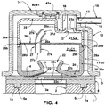
- the present invention will be described for a refrigeration compressor of the reciprocating hermetic type and comprising a motor-compressor assembly (not illustrated), including a cylinder crankcase 1 (partially illustrated in figure 4 ), which defines a cylinder 2 inside which a piston is axially displaced (not illustrated), by action of a rotary or linear electric motor.
- a motor-compressor assembly (not illustrated), including a cylinder crankcase 1 (partially illustrated in figure 4 ), which defines a cylinder 2 inside which a piston is axially displaced (not illustrated), by action of a rotary or linear electric motor.
- the cylinder crankcase 1 may be built in any suitable metal alloy, well known in the state of the art.
- the cylinder 2 has an open end, through which the piston is mounted, and an opposite end (illustrated in figure 4 ), closed by a valve plate 3, against which is seated a usually metallic cylinder cap 10.
- the valve plate 3 is built in a metal alloy, in order to operate together with at least one suction valve, not illustrated, facing the interior of the cylinder 2, and with at least one discharge valve 4 which, in the illustrated example, takes the form of a single plate incorporating a metallic flexible blade 4a, operating in association with a respective discharge orifice 3a of the valve plate 3.
- the discharge valve may take the form of a single plate incorporating a plurality of flexible blades, each operating in association with a respective discharge orifice provided in the valve plate 3.
- valve plate 3 is seated on the cylinder crankcase 1, by means of an annular sealing gasket 5. Although not illustrated in the drawings, it may be further provided another annular sealing gasket located between the cylinder cap 10 and the adjacent face of the valve plate 3.
- the cylinder cap 10 is seated against one face of the valve plate 3, opposite to that seated against the cylinder crankcase 1.
- the cylinder cap 10 defines, with the adjacent face of the valve plate 3, a discharge chamber 11, which maintains a selective fluid communication with the cylinder 2, through the discharge orifice 3a or through the multiple discharge orifices, if existent, upon the opening of the discharge valve 4, and a constant fluid communication with a discharge side of a refrigeration system to which the compressor is associated, through a discharge tube (not illustrated), which connects said discharge chamber 11 to the exterior of the compressor.
- the cylinder cap 10 takes the form of a cup, with its open base seated on the valve plate 3 and defining a gas inlet 12 in fluid communication with the discharge orifice 3a, and a gas outlet 13, coupled to the discharge tube which communicates said gas outlet 13 with the exterior of the compressor.
- the cylinder cap 10 is provided with an end wall 14, opposed to its open base and to the valve plate 3.
- the gas outlet 13 is provided in a chamfered region 15 of the end wall 14 and located facing laterally outwards of the cylinder cap 10.
- said positioning of the gas outlet 13 should not be limited to the illustrated embodiment, and the gas outlet 13 may be provided in the end wall 14 of the cylinder cap 10.
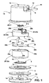
- the present invention provides a refrigeration compressor having a thermal insulation system for the discharge of gas, said system comprising a hollow body 20, preferably but not necessarily, formed of a thermal insulating material, defining at least one plenum 21 therein and mounted, in an indexed manner, inside the cylinder cap 10, keeping with the latter a gap 30 and being seated against the valve plate 3, preventing a direct contact of the latter with the internal volume of the hollow body 20.
- the plenum 21 of the hollow body 20 effectively acts as a discharge chamber.
- the discharge chamber 11 of the cylinder cap 10 acts, in this embodiment, in the definition of the volume of the gap 30 between the inner walls of the cylinder cap 10 and the hollow body 20.
- the assembly of the cylinder cap 10 and hollow body 20 may be carried out in order to make the gap 30 hermetic in relation to the interior of the hollow body 20 and to the exterior of the cylinder cap 10.
- the hollow body 20 is provided with an inlet nozzle 22, open to the plenum 21 and to the discharge orifice 3a of the valve plate 3, and with an outlet nozzle 23, communicating the plenum 21 with the gas outlet 13 of the cylinder cap 10.
- the hollow body 20 comprises a base end wall 24 to be seated against the valve plate 3, in order to secure thereto the discharge valve 4 and to define a stop for the latter, with the inlet nozzle 22 being provided in said base end wall 24 and open to the discharge orifice 3a of the valve plate 3.
- the annular sealing gasket 5 is provided with at least two diametrically opposite eccentric axial projections 5a, which are dimensioned to be fitted in respective recesses 1a defined in a confronting face of the cylinder crankcase 1, allowing for the correct indexation in the seating of the annular sealing gasket 5 against the cylinder crankcase 1.
- the base end wall 24 may incorporate a plurality of base projections facing outwards the hollow body 20, indexing the hollow body 20 in relation to the valve plate 3 and also in relation to the annular sealing gasket 5 and to the cylinder crankcase 1.
- the inlet nozzle 22 of the hollow body 20 comprises a base opening 22a provided in the base end wall 24, and a tubular projection 22b which extends from the base end wall 24 to the interior of the hollow body 20, around the base opening 22a thereof.
- annular region 22c of the base wall 24 surrounding the base opening 22a of the inlet nozzle 22 is constructed so as be axially spaced from the valve plate 3, defining a stop for the opening of the flexible blade 4a of the discharge valve 4.
- said annular region 22c of the base wall 24 is located inclined radially inwards and axially inwards the hollow body 20, defining an inclined opening stop against which is seated the flexible blade 4a upon the opening of the discharge valve 4.
- the tubular projection 22b of the inlet nozzle 22 presents a frusto-conical configuration, with the larger base open and facing the interior of the hollow body 20. This constructive arrangement of the inlet nozzle 22 reduces the discharge power (consumption in the discharge process) and minimizes the pulsation transients.
- the hollow body 20 comprises a top end wall 25 in which is provided the outlet nozzle 23 of the hollow body 20, said outlet nozzle 23 being open to the gas outlet 13 of the cylinder cap 10.
- the outlet nozzle 23 of the hollow body 20 comprises an outer tubular projection 23a which extends outside from a lowered region 25a of the top end wall 25 of the hollow body 20, to be fitted in a tubular passage 16 formed internally to the end wall 14 and which is open to the outlet opening 13 of the cylinder cap 10.
- the outlet opening 13 of the cylinder cap 10 is configured to receive and secure, in its interior and by any suitable means, such as for example threads, adhesives or brazing, a tubular connector 18 which projects outside from the outlet opening 13, in order to be coupled to an adjacent end of the discharge tube, not illustrated, which connects the discharge chamber 11 to the exterior of the compressor.
- the cylinder cap may incorporate a support element, not illustrated, which is configured to be coupled to the suspension system of the compression mechanism, inside the compressor housing.
- the cylinder cap does not need to incorporate said support element.
- the refrigeration compressor of the present invention further provides a biasing means 40 located between the top end wall 25 of the hollow body 20 and the end wall 14 of the cylinder cap 10, in order to constantly and elastically force the hollow body 20 against the valve plate 3, minimizing the passage of the discharge gas to the interior of the cylinder cap 10, externally to the hollow body 20.
- the biasing means 40 forces the base end wall 24 against the valve plate 3, improving the securing and limiting (stopping) functions of the base end wall 24 in relation to the discharge valve 4.
- the biasing means 40 further improves the sealing of the hollow body 20 in relation to the gap 30.
- the biasing means 40 is defined by a plate spring 41, generally formed by parallel rods joined by their ends 41a, the latter being each fitted externally to a respective top projection 25b of the top end wall 25 of the hollow body 20.
- the top end wall 25 of the hollow body 20 may incorporate a plurality of top projections facing outwards of the hollow body 20, and the end wall 14 of the cylinder cap 10 may be internally provided with an equal plurality of recesses, inside which is fitted a respective top projection of the top end wall 25, indexing, relative to each other, the hollow body 20 and the cylinder cap 10.
- the plate spring 41 may have each of its ends fitted inside a respective top projection of the top end wall 25.
- the hollow body 20 is formed of two parts 20a, 20b, one incorporating the base end wall 24 and the other incorporating the top end wall 25, said parts being seated against a common dividing wall 26 which divides the plenum 21 of the hollow body 20 into a first and into a second discharge chamber C1, C2, said dividing wall 26 presenting an opening 26a communicating both discharge chambers C1, C2.
- sealing means between the two parts 20a, 20b of the hollow body 20 and the common dividing wall 26, which sealing means may be defined in different manners, such as for example, by an adhesive film or by sealing gaskets.
- the part 20a of the hollow body 20 closer to the valve plate 3 presents an end edge 28a, facing the common dividing wall 26 and provided with at least two outer cutouts 29a configured to perform the function described below.
- the other part 20b of the hollow body 20 has an end edge 28b, facing the common dividing wall 26 and incorporating at least two axial projections 29b dimensioned to be fitted and each preferably retained into a respective outer cutout 29a of the other part 20a of the hollow body 20.
- the common dividing wall 26 presents at least two radial cutouts/notches 26b dimensioned to allow the passage of the axial projections 29b of the part 20b of the hollow body 20, upon closing the latter.
- the hollow body 20 may be formed in a single piece defining a single discharge chamber, or also formed in two or more parts, as illustrated, however having the dividing wall incorporated to one of said parts.
- the hollow body 20 may further present more than two discharge chambers in the interior thereof.
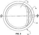
- the opening 26a of the dividing wall 26 receives, hermetically, a tube 27 which projects to the interior of the first discharge chamber C1, through a straight section 27a eccentric in relation to the inlet nozzle 22 of the hollow body 20, and to the interior of the second discharge chamber C2, through an arcuate section 27b.
- the tube 27 may be built and dimensioned in order to define an acoustic attenuator.
- the illustrated tube 27 is obtained in a separate piece from the median wall 26, it should be understood that said tube may be provided in a single piece with said median wall.
- the median wall 26 may be disposed in different positions, not necessarily horizontal or substantially horizontal, and may even be arranged in a substantially vertical or inclined manner.
- the first and the second discharge chambers C1, C2 may present equal or different volumes and also communicate with each other by more than one opening 26a or more than one tube 27.
- the first discharge chamber C1 receives, from the inlet nozzle 22 of the hollow body 20, the entire discharge flow coming from the compression chamber, said first discharge chamber C1 maintaining a constant fluid communication with the second discharge chamber C2, through the tube 27.
- thermally insulated discharge system of the refrigeration compressor according to the present invention also acts as an acoustic muffler during the discharge of gas in the gas compression upon operation of the compressor.
- each of the first and second discharge chambers C1, C2, as well as the determination of the dimensions of each tube 27 (length, shape, cross section) and the definition of its projecting extension to the interior of each chamber in which said tube acts, are defined in function of the thermal insulation effect to be achieved, however they may also be defined in function of the attenuation to be achieved and of the pulsation range to be attenuated.
- the hollow body 20 may further present a plurality of discharge chambers located according to the same concept described for both discharge chambers illustrated in the drawings.
- the tube 27 presents a first end 27c and a second end 27d eccentrically located in the first and second discharge chambers C1, C2, with the first end 27c of the tube 27 being located eccentrically to the inlet nozzle 22 of the hollow body 20, and with the second end 27d of the tube 27 being located spaced from the gas outlet opening 22 of the hollow body 20.
- the gas outlet opening 22 is disposed in direct fluid communication with the gas outlet 13 of the cylinder cap 10.
- the gas outlet opening 22 is provided located orthogonal to the gas outlet 13 of the cylinder cap 10 and connected to said gas outlet 13 by means of the tubular passage 16 provided internally to the end wall 14 of the cylinder cap 10.
- the thermal insulation system of the refrigeration compressor of the present invention is distinguished from the known solutions, by promoting a substantial increase in the total resistance to the thermal exchange between the compressed gas contained inside the hollow body 20 and the environment internal to the compressor housing.
- the provision of the hollow body 20, preferably formed in a thermal insulating material, such as plastic, causes the heat of the compressed gas contained within the hollow body to reach, by internal convection, the wall of the hollow body 20 and hence, by means of conduction through the material with which the hollow body 20 is built, the gap 30 defined between the hollow body 20 and the cylinder cap 10, and which defines an effective thermal insulation element against the heat that tends to migrate to the cylinder cap 10 and from the latter, by convection, to the interior of the hermetic housing of the compressor.
- This construction creates, in relation to the prior art, at least one additional thermal resistance means defined by the gap 30 between the hollow body 20 and the cylinder cap 10, which is not foreseen by the state of the art and also, preferably, a second additional thermal resistance means defined by the wall of the hollow body 20 when built in a thermal insulating material.
- the present invention provides an improved thermal insulation, even if variations occur: in the value of the gap existing between the metallic wall of the cylinder cap 10 and the wall in insulating material of the hollow body 20; in the number of internal divisions of the hollow body 20; in the shape of the chambers inside the hollow body 20; and in the determination of the type of insulating material (for example, a composition formed of more than one material for the hollow body 20).
Landscapes
- Engineering & Computer Science (AREA)
- General Engineering & Computer Science (AREA)
- Mechanical Engineering (AREA)
- Compressor (AREA)
Applications Claiming Priority (2)
| Application Number | Priority Date | Filing Date | Title |
|---|---|---|---|
| BR102012025273-2A BR102012025273B1 (pt) | 2012-10-03 | 2012-10-03 | Compressor de refrigeração |
| PCT/BR2013/000394 WO2014053040A1 (en) | 2012-10-03 | 2013-10-02 | Thermal insulation system for the discharge of gas in a refrigeration compressor |
Publications (2)
| Publication Number | Publication Date |
|---|---|
| EP2912315A1 EP2912315A1 (en) | 2015-09-02 |
| EP2912315B1 true EP2912315B1 (en) | 2018-09-05 |
Family
ID=49596017
Family Applications (1)
| Application Number | Title | Priority Date | Filing Date |
|---|---|---|---|
| EP13792244.9A Active EP2912315B1 (en) | 2012-10-03 | 2013-10-02 | Thermal insulation system for the discharge of gas in a refrigeration compressor |
Country Status (10)
| Country | Link |
|---|---|
| US (1) | US9909581B2 (enExample) |
| EP (1) | EP2912315B1 (enExample) |
| JP (1) | JP6225191B2 (enExample) |
| CN (1) | CN104797820B (enExample) |
| AU (1) | AU2013327353A1 (enExample) |
| BR (1) | BR102012025273B1 (enExample) |
| ES (1) | ES2692655T3 (enExample) |
| MX (1) | MX355382B (enExample) |
| NZ (1) | NZ706406A (enExample) |
| WO (1) | WO2014053040A1 (enExample) |
Cited By (1)
| Publication number | Priority date | Publication date | Assignee | Title |
|---|---|---|---|---|
| EP4424992A1 (en) * | 2023-02-28 | 2024-09-04 | ZF Commercial Vehicle Systems (Qingdao) Co., Ltd. | Air compressor cylinder head and air compressor |
Families Citing this family (12)
| Publication number | Priority date | Publication date | Assignee | Title |
|---|---|---|---|---|
| CN107636404B (zh) * | 2015-07-03 | 2020-03-27 | 三菱电机株式会社 | 热泵装置 |
| BR102016005387A2 (pt) * | 2016-03-11 | 2017-09-19 | Whirlpool S.A. | Discharge acoustic filter, process of manufacture of acoustic discharge filter and hermetic compressor |
| BR102016029873A2 (pt) * | 2016-12-19 | 2018-07-17 | Whirlpool S.A. | compressor hermético |
| TR201717699A2 (tr) * | 2017-11-10 | 2019-05-21 | Arcelik As | Sizdirmazliği i̇yi̇leşti̇ri̇len hermeti̇k kompresör |
| KR102424613B1 (ko) * | 2018-04-10 | 2022-07-25 | 엘지전자 주식회사 | 리니어 압축기 |
| KR102060175B1 (ko) * | 2018-06-29 | 2019-12-27 | 엘지전자 주식회사 | 리니어 압축기 |
| KR102215909B1 (ko) * | 2019-08-23 | 2021-02-16 | 엘지전자 주식회사 | 리니어 압축기 |
| DE102021205041A1 (de) * | 2021-05-18 | 2022-11-24 | Thyssenkrupp Ag | Kolbenverdichter, insbesondere Radialkolbenverdichter |
| CN113357123B (zh) * | 2021-07-08 | 2022-11-15 | 珠海格力节能环保制冷技术研究中心有限公司 | 阀板结构、压缩机以及具有其的电器 |
| CN216812061U (zh) * | 2021-10-25 | 2022-06-24 | 思科普有限责任公司 | 封装式制冷剂压缩机的排出消声器和封装式制冷剂压缩机 |
| KR102674873B1 (ko) * | 2022-09-27 | 2024-06-14 | 엘지전자 주식회사 | 리니어 압축기 |
| US20250271185A1 (en) * | 2024-02-23 | 2025-08-28 | Copeland Lp | Thermal Barriers For Compressor Discharge Chambers or Cavities |
Family Cites Families (12)
| Publication number | Priority date | Publication date | Assignee | Title |
|---|---|---|---|---|
| CH249217A (de) * | 1944-08-03 | 1947-06-15 | Sulzer Ag | Verfahren zur Unterdrückung von Schwingungen an Abschlussorganen, die vom Strom des Fördermittels gesteuert sind, und Vorrichtung zur Ausführung des Verfahrens. |
| JPS61207884A (ja) | 1985-03-12 | 1986-09-16 | Diesel Kiki Co Ltd | 圧縮機の脈動低減機構 |
| US5530214A (en) * | 1994-09-20 | 1996-06-25 | The United States Of America As Represented By The Secretary Of The Navy | Venturi muffler |
| JP4019720B2 (ja) * | 2002-01-24 | 2007-12-12 | 株式会社豊田自動織機 | 圧縮機 |
| DE10323526B3 (de) * | 2003-05-24 | 2005-02-03 | Danfoss Compressors Gmbh | Saugschalldämpfer für einen hermetischen Kältemittelverdichter |
| JP4104534B2 (ja) | 2003-11-13 | 2008-06-18 | 株式会社デンソー | 密閉型圧縮機 |
| JP4552432B2 (ja) * | 2003-12-11 | 2010-09-29 | ダイキン工業株式会社 | 圧縮機 |
| BRPI0505717B1 (pt) * | 2005-12-16 | 2020-03-10 | Embraco Indústria De Compressores E Soluções Em Refrigeração Ltda | Compressor hermético com isolamento térmico interno |
| AT10136U1 (de) | 2007-10-05 | 2008-09-15 | Acc Austria Gmbh | Kältemittelverdichter |
| BRPI0705357A2 (pt) * | 2007-12-26 | 2009-08-25 | Whirlpool Sa | sistema para atenuação de pulsação na descarga de gás em um compressor de refrigeração |
| BRPI0803457B1 (pt) * | 2008-09-05 | 2020-11-10 | Embraco Indústria De Compressores E Soluções Em Refrigeração Ltda | arranjo de sucção para compressor hermético de refrigeração |
| BRPI0900855A2 (pt) * | 2009-04-06 | 2010-12-28 | Whirlpool Sa | arranjo construtivo para compressor hermético de refrigeração |
-
2012
- 2012-10-03 BR BR102012025273-2A patent/BR102012025273B1/pt not_active IP Right Cessation
-
2013
- 2013-10-02 WO PCT/BR2013/000394 patent/WO2014053040A1/en not_active Ceased
- 2013-10-02 NZ NZ706406A patent/NZ706406A/en not_active IP Right Cessation
- 2013-10-02 AU AU2013327353A patent/AU2013327353A1/en not_active Abandoned
- 2013-10-02 JP JP2015534890A patent/JP6225191B2/ja not_active Expired - Fee Related
- 2013-10-02 CN CN201380061030.7A patent/CN104797820B/zh not_active Expired - Fee Related
- 2013-10-02 US US14/433,188 patent/US9909581B2/en active Active
- 2013-10-02 EP EP13792244.9A patent/EP2912315B1/en active Active
- 2013-10-02 ES ES13792244.9T patent/ES2692655T3/es active Active
- 2013-10-02 MX MX2015004344A patent/MX355382B/es active IP Right Grant
Cited By (1)
| Publication number | Priority date | Publication date | Assignee | Title |
|---|---|---|---|---|
| EP4424992A1 (en) * | 2023-02-28 | 2024-09-04 | ZF Commercial Vehicle Systems (Qingdao) Co., Ltd. | Air compressor cylinder head and air compressor |
Also Published As
| Publication number | Publication date |
|---|---|
| JP6225191B2 (ja) | 2017-11-01 |
| AU2013327353A1 (en) | 2015-04-16 |
| JP2015530520A (ja) | 2015-10-15 |
| MX355382B (es) | 2018-04-17 |
| BR102012025273B1 (pt) | 2021-09-08 |
| ES2692655T3 (es) | 2018-12-04 |
| NZ706406A (en) | 2017-11-24 |
| CN104797820A (zh) | 2015-07-22 |
| BR102012025273A2 (pt) | 2014-08-26 |
| EP2912315A1 (en) | 2015-09-02 |
| US20150275883A1 (en) | 2015-10-01 |
| US9909581B2 (en) | 2018-03-06 |
| MX2015004344A (es) | 2015-06-10 |
| CN104797820B (zh) | 2017-05-24 |
| WO2014053040A1 (en) | 2014-04-10 |
Similar Documents
| Publication | Publication Date | Title |
|---|---|---|
| EP2912315B1 (en) | Thermal insulation system for the discharge of gas in a refrigeration compressor | |
| EP2265821B1 (en) | Muffler for compressor | |
| EP2912314B1 (en) | Gas discharge system for a refrigeration compressor and a refrigeration compressor | |
| EP2859235B1 (en) | A compressor comprising a cylinder head | |
| EP2329146B1 (en) | Suction arrangement for a hermetic refrigeration compressor | |
| US8257061B2 (en) | Hermetic compressor with internal thermal insulation | |
| JP2015530519A6 (ja) | 冷凍圧縮機用ガス排気システムおよび冷凍圧縮機 | |
| CN102119275A (zh) | 用于封闭式压缩机的排出阀装置 | |
| JP5411348B2 (ja) | 密閉冷凍圧縮機の構造的配置 | |
| EP2891801B1 (en) | Compressor and valve assembly thereof for reducing pulsation and/or noise | |
| EP2873864A1 (en) | Rotary compressor | |
| EP2935886B1 (en) | Suction muffler for a linear motor compressor and a linear motor compressor | |
| KR20150067284A (ko) | 냉동 컴프레서에서 가스를 배출하기 위한 열 절연 시스템 | |
| CN211474433U (zh) | 压缩机和制冷设备 | |
| EP1853822B1 (en) | A compressor | |
| EP2917575A1 (en) | Compressor comprising cylinder head | |
| JP6186593B2 (ja) | ロータリ圧縮機 | |
| US20050226740A1 (en) | Compressor having rear housing structure to reduce the operating temperature | |
| WO2009132955A1 (en) | A compressor |
Legal Events
| Date | Code | Title | Description |
|---|---|---|---|
| PUAI | Public reference made under article 153(3) epc to a published international application that has entered the european phase |
Free format text: ORIGINAL CODE: 0009012 |
|
| 17P | Request for examination filed |
Effective date: 20150504 |
|
| AK | Designated contracting states |
Kind code of ref document: A1 Designated state(s): AL AT BE BG CH CY CZ DE DK EE ES FI FR GB GR HR HU IE IS IT LI LT LU LV MC MK MT NL NO PL PT RO RS SE SI SK SM TR |
|
| AX | Request for extension of the european patent |
Extension state: BA ME |
|
| DAX | Request for extension of the european patent (deleted) | ||
| GRAP | Despatch of communication of intention to grant a patent |
Free format text: ORIGINAL CODE: EPIDOSNIGR1 |
|
| INTG | Intention to grant announced |
Effective date: 20180316 |
|
| GRAS | Grant fee paid |
Free format text: ORIGINAL CODE: EPIDOSNIGR3 |
|
| GRAA | (expected) grant |
Free format text: ORIGINAL CODE: 0009210 |
|
| AK | Designated contracting states |
Kind code of ref document: B1 Designated state(s): AL AT BE BG CH CY CZ DE DK EE ES FI FR GB GR HR HU IE IS IT LI LT LU LV MC MK MT NL NO PL PT RO RS SE SI SK SM TR |
|
| REG | Reference to a national code |
Ref country code: GB Ref legal event code: FG4D |
|
| REG | Reference to a national code |
Ref country code: CH Ref legal event code: EP |
|
| REG | Reference to a national code |
Ref country code: AT Ref legal event code: REF Ref document number: 1038128 Country of ref document: AT Kind code of ref document: T Effective date: 20180915 |
|
| REG | Reference to a national code |
Ref country code: DE Ref legal event code: R096 Ref document number: 602013043233 Country of ref document: DE |
|
| REG | Reference to a national code |
Ref country code: IE Ref legal event code: FG4D |
|
| REG | Reference to a national code |
Ref country code: ES Ref legal event code: FG2A Ref document number: 2692655 Country of ref document: ES Kind code of ref document: T3 Effective date: 20181204 |
|
| REG | Reference to a national code |
Ref country code: NL Ref legal event code: MP Effective date: 20180905 |
|
| REG | Reference to a national code |
Ref country code: LT Ref legal event code: MG4D |
|
| PG25 | Lapsed in a contracting state [announced via postgrant information from national office to epo] |
Ref country code: SE Free format text: LAPSE BECAUSE OF FAILURE TO SUBMIT A TRANSLATION OF THE DESCRIPTION OR TO PAY THE FEE WITHIN THE PRESCRIBED TIME-LIMIT Effective date: 20180905 Ref country code: FI Free format text: LAPSE BECAUSE OF FAILURE TO SUBMIT A TRANSLATION OF THE DESCRIPTION OR TO PAY THE FEE WITHIN THE PRESCRIBED TIME-LIMIT Effective date: 20180905 Ref country code: RS Free format text: LAPSE BECAUSE OF FAILURE TO SUBMIT A TRANSLATION OF THE DESCRIPTION OR TO PAY THE FEE WITHIN THE PRESCRIBED TIME-LIMIT Effective date: 20180905 Ref country code: LT Free format text: LAPSE BECAUSE OF FAILURE TO SUBMIT A TRANSLATION OF THE DESCRIPTION OR TO PAY THE FEE WITHIN THE PRESCRIBED TIME-LIMIT Effective date: 20180905 Ref country code: BG Free format text: LAPSE BECAUSE OF FAILURE TO SUBMIT A TRANSLATION OF THE DESCRIPTION OR TO PAY THE FEE WITHIN THE PRESCRIBED TIME-LIMIT Effective date: 20181205 Ref country code: NO Free format text: LAPSE BECAUSE OF FAILURE TO SUBMIT A TRANSLATION OF THE DESCRIPTION OR TO PAY THE FEE WITHIN THE PRESCRIBED TIME-LIMIT Effective date: 20181205 |
|
| REG | Reference to a national code |
Ref country code: AT Ref legal event code: MK05 Ref document number: 1038128 Country of ref document: AT Kind code of ref document: T Effective date: 20180905 |
|
| PG25 | Lapsed in a contracting state [announced via postgrant information from national office to epo] |
Ref country code: AL Free format text: LAPSE BECAUSE OF FAILURE TO SUBMIT A TRANSLATION OF THE DESCRIPTION OR TO PAY THE FEE WITHIN THE PRESCRIBED TIME-LIMIT Effective date: 20180905 Ref country code: HR Free format text: LAPSE BECAUSE OF FAILURE TO SUBMIT A TRANSLATION OF THE DESCRIPTION OR TO PAY THE FEE WITHIN THE PRESCRIBED TIME-LIMIT Effective date: 20180905 Ref country code: LV Free format text: LAPSE BECAUSE OF FAILURE TO SUBMIT A TRANSLATION OF THE DESCRIPTION OR TO PAY THE FEE WITHIN THE PRESCRIBED TIME-LIMIT Effective date: 20180905 |
|
| REG | Reference to a national code |
Ref country code: SK Ref legal event code: T3 Ref document number: E 28938 Country of ref document: SK |
|
| REG | Reference to a national code |
Ref country code: ES Ref legal event code: PC2A Owner name: EMBRACO INDUSTRIA DE COMPRESSORES E SOLUSOES EM RE Effective date: 20190227 |
|
| REG | Reference to a national code |
Ref country code: DE Ref legal event code: R081 Ref document number: 602013043233 Country of ref document: DE Owner name: EMBRACO INDUSTRIA DE COMPRESSORES E SOLUCOES E, BR Free format text: FORMER OWNER: WHIRLPOOL S.A., SAO PAULO, BR |
|
| PG25 | Lapsed in a contracting state [announced via postgrant information from national office to epo] |
Ref country code: PL Free format text: LAPSE BECAUSE OF FAILURE TO SUBMIT A TRANSLATION OF THE DESCRIPTION OR TO PAY THE FEE WITHIN THE PRESCRIBED TIME-LIMIT Effective date: 20180905 Ref country code: EE Free format text: LAPSE BECAUSE OF FAILURE TO SUBMIT A TRANSLATION OF THE DESCRIPTION OR TO PAY THE FEE WITHIN THE PRESCRIBED TIME-LIMIT Effective date: 20180905 Ref country code: NL Free format text: LAPSE BECAUSE OF FAILURE TO SUBMIT A TRANSLATION OF THE DESCRIPTION OR TO PAY THE FEE WITHIN THE PRESCRIBED TIME-LIMIT Effective date: 20180905 Ref country code: AT Free format text: LAPSE BECAUSE OF FAILURE TO SUBMIT A TRANSLATION OF THE DESCRIPTION OR TO PAY THE FEE WITHIN THE PRESCRIBED TIME-LIMIT Effective date: 20180905 Ref country code: RO Free format text: LAPSE BECAUSE OF FAILURE TO SUBMIT A TRANSLATION OF THE DESCRIPTION OR TO PAY THE FEE WITHIN THE PRESCRIBED TIME-LIMIT Effective date: 20180905 Ref country code: CZ Free format text: LAPSE BECAUSE OF FAILURE TO SUBMIT A TRANSLATION OF THE DESCRIPTION OR TO PAY THE FEE WITHIN THE PRESCRIBED TIME-LIMIT Effective date: 20180905 Ref country code: IS Free format text: LAPSE BECAUSE OF FAILURE TO SUBMIT A TRANSLATION OF THE DESCRIPTION OR TO PAY THE FEE WITHIN THE PRESCRIBED TIME-LIMIT Effective date: 20190105 |
|
| PG25 | Lapsed in a contracting state [announced via postgrant information from national office to epo] |
Ref country code: PT Free format text: LAPSE BECAUSE OF FAILURE TO SUBMIT A TRANSLATION OF THE DESCRIPTION OR TO PAY THE FEE WITHIN THE PRESCRIBED TIME-LIMIT Effective date: 20190105 Ref country code: SM Free format text: LAPSE BECAUSE OF FAILURE TO SUBMIT A TRANSLATION OF THE DESCRIPTION OR TO PAY THE FEE WITHIN THE PRESCRIBED TIME-LIMIT Effective date: 20180905 |
|
| REG | Reference to a national code |
Ref country code: CH Ref legal event code: PL |
|
| REG | Reference to a national code |
Ref country code: SK Ref legal event code: PC4A Ref document number: E 28938 Country of ref document: SK Owner name: EMBRACO INDUSTRIA DE COMPRESSORES E SOLUCOES E, BR Free format text: FORMER OWNER: WHIRLPOOL S.A., SAO PAULO SP, BR Effective date: 20190503 |
|
| REG | Reference to a national code |
Ref country code: DE Ref legal event code: R097 Ref document number: 602013043233 Country of ref document: DE |
|
| REG | Reference to a national code |
Ref country code: BE Ref legal event code: MM Effective date: 20181031 |
|
| PG25 | Lapsed in a contracting state [announced via postgrant information from national office to epo] |
Ref country code: LU Free format text: LAPSE BECAUSE OF NON-PAYMENT OF DUE FEES Effective date: 20181002 |
|
| PLBE | No opposition filed within time limit |
Free format text: ORIGINAL CODE: 0009261 |
|
| STAA | Information on the status of an ep patent application or granted ep patent |
Free format text: STATUS: NO OPPOSITION FILED WITHIN TIME LIMIT |
|
| REG | Reference to a national code |
Ref country code: IE Ref legal event code: MM4A |
|
| PG25 | Lapsed in a contracting state [announced via postgrant information from national office to epo] |
Ref country code: DK Free format text: LAPSE BECAUSE OF FAILURE TO SUBMIT A TRANSLATION OF THE DESCRIPTION OR TO PAY THE FEE WITHIN THE PRESCRIBED TIME-LIMIT Effective date: 20180905 Ref country code: MC Free format text: LAPSE BECAUSE OF FAILURE TO SUBMIT A TRANSLATION OF THE DESCRIPTION OR TO PAY THE FEE WITHIN THE PRESCRIBED TIME-LIMIT Effective date: 20180905 |
|
| 26N | No opposition filed |
Effective date: 20190606 |
|
| GBPC | Gb: european patent ceased through non-payment of renewal fee |
Effective date: 20181205 |
|
| PG25 | Lapsed in a contracting state [announced via postgrant information from national office to epo] |
Ref country code: SI Free format text: LAPSE BECAUSE OF FAILURE TO SUBMIT A TRANSLATION OF THE DESCRIPTION OR TO PAY THE FEE WITHIN THE PRESCRIBED TIME-LIMIT Effective date: 20180905 Ref country code: CH Free format text: LAPSE BECAUSE OF NON-PAYMENT OF DUE FEES Effective date: 20181031 Ref country code: LI Free format text: LAPSE BECAUSE OF NON-PAYMENT OF DUE FEES Effective date: 20181031 Ref country code: BE Free format text: LAPSE BECAUSE OF NON-PAYMENT OF DUE FEES Effective date: 20181031 |
|
| PG25 | Lapsed in a contracting state [announced via postgrant information from national office to epo] |
Ref country code: IE Free format text: LAPSE BECAUSE OF NON-PAYMENT OF DUE FEES Effective date: 20181002 Ref country code: FR Free format text: LAPSE BECAUSE OF NON-PAYMENT OF DUE FEES Effective date: 20181105 |
|
| PG25 | Lapsed in a contracting state [announced via postgrant information from national office to epo] |
Ref country code: GB Free format text: LAPSE BECAUSE OF NON-PAYMENT OF DUE FEES Effective date: 20181205 |
|
| PG25 | Lapsed in a contracting state [announced via postgrant information from national office to epo] |
Ref country code: MT Free format text: LAPSE BECAUSE OF NON-PAYMENT OF DUE FEES Effective date: 20181002 |
|
| PG25 | Lapsed in a contracting state [announced via postgrant information from national office to epo] |
Ref country code: HU Free format text: LAPSE BECAUSE OF FAILURE TO SUBMIT A TRANSLATION OF THE DESCRIPTION OR TO PAY THE FEE WITHIN THE PRESCRIBED TIME-LIMIT; INVALID AB INITIO Effective date: 20131002 Ref country code: CY Free format text: LAPSE BECAUSE OF FAILURE TO SUBMIT A TRANSLATION OF THE DESCRIPTION OR TO PAY THE FEE WITHIN THE PRESCRIBED TIME-LIMIT Effective date: 20180905 Ref country code: GR Free format text: LAPSE BECAUSE OF FAILURE TO SUBMIT A TRANSLATION OF THE DESCRIPTION OR TO PAY THE FEE WITHIN THE PRESCRIBED TIME-LIMIT Effective date: 20180905 Ref country code: MK Free format text: LAPSE BECAUSE OF NON-PAYMENT OF DUE FEES Effective date: 20180905 |
|
| PGFP | Annual fee paid to national office [announced via postgrant information from national office to epo] |
Ref country code: TR Payment date: 20220930 Year of fee payment: 10 Ref country code: SK Payment date: 20220926 Year of fee payment: 10 |
|
| PGFP | Annual fee paid to national office [announced via postgrant information from national office to epo] |
Ref country code: IT Payment date: 20221026 Year of fee payment: 10 Ref country code: ES Payment date: 20221222 Year of fee payment: 10 Ref country code: DE Payment date: 20221019 Year of fee payment: 10 |
|
| REG | Reference to a national code |
Ref country code: DE Ref legal event code: R119 Ref document number: 602013043233 Country of ref document: DE |
|
| REG | Reference to a national code |
Ref country code: SK Ref legal event code: MM4A Ref document number: E 28938 Country of ref document: SK Effective date: 20231002 |
|
| PG25 | Lapsed in a contracting state [announced via postgrant information from national office to epo] |
Ref country code: SK Free format text: LAPSE BECAUSE OF NON-PAYMENT OF DUE FEES Effective date: 20231002 |
|
| PG25 | Lapsed in a contracting state [announced via postgrant information from national office to epo] |
Ref country code: SK Free format text: LAPSE BECAUSE OF NON-PAYMENT OF DUE FEES Effective date: 20231002 Ref country code: DE Free format text: LAPSE BECAUSE OF NON-PAYMENT OF DUE FEES Effective date: 20240501 |
|
| REG | Reference to a national code |
Ref country code: ES Ref legal event code: FD2A Effective date: 20241126 |
|
| PG25 | Lapsed in a contracting state [announced via postgrant information from national office to epo] |
Ref country code: IT Free format text: LAPSE BECAUSE OF NON-PAYMENT OF DUE FEES Effective date: 20231002 |
|
| PG25 | Lapsed in a contracting state [announced via postgrant information from national office to epo] |
Ref country code: IT Free format text: LAPSE BECAUSE OF NON-PAYMENT OF DUE FEES Effective date: 20231002 |
|
| PG25 | Lapsed in a contracting state [announced via postgrant information from national office to epo] |
Ref country code: ES Free format text: LAPSE BECAUSE OF NON-PAYMENT OF DUE FEES Effective date: 20231003 |
|
| PG25 | Lapsed in a contracting state [announced via postgrant information from national office to epo] |
Ref country code: ES Free format text: LAPSE BECAUSE OF NON-PAYMENT OF DUE FEES Effective date: 20231003 |