EP2910395A2 - Engrenage planétaire solidaire d'un frein de service intégral - Google Patents
Engrenage planétaire solidaire d'un frein de service intégral Download PDFInfo
- Publication number
- EP2910395A2 EP2910395A2 EP14195417.2A EP14195417A EP2910395A2 EP 2910395 A2 EP2910395 A2 EP 2910395A2 EP 14195417 A EP14195417 A EP 14195417A EP 2910395 A2 EP2910395 A2 EP 2910395A2
- Authority
- EP
- European Patent Office
- Prior art keywords
- service brake
- brake
- oil
- parking brake
- service
- Prior art date
- Legal status (The legal status is an assumption and is not a legal conclusion. Google has not performed a legal analysis and makes no representation as to the accuracy of the status listed.)
- Granted
Links
- 239000003921 oil Substances 0.000 claims description 137
- 230000008878 coupling Effects 0.000 claims description 31
- 238000010168 coupling process Methods 0.000 claims description 31
- 238000005859 coupling reaction Methods 0.000 claims description 31
- 239000002783 friction material Substances 0.000 claims description 20
- 239000010687 lubricating oil Substances 0.000 claims description 11
- 238000005086 pumping Methods 0.000 claims description 4
- 230000017525 heat dissipation Effects 0.000 claims description 2
- 239000002826 coolant Substances 0.000 claims 1
- 238000001816 cooling Methods 0.000 abstract description 2
- 238000007789 sealing Methods 0.000 description 5
- 239000000314 lubricant Substances 0.000 description 4
- 239000012530 fluid Substances 0.000 description 3
- 239000000463 material Substances 0.000 description 3
- 229910000906 Bronze Inorganic materials 0.000 description 2
- 239000010974 bronze Substances 0.000 description 2
- KUNSUQLRTQLHQQ-UHFFFAOYSA-N copper tin Chemical compound [Cu].[Sn] KUNSUQLRTQLHQQ-UHFFFAOYSA-N 0.000 description 2
- 230000002706 hydrostatic effect Effects 0.000 description 2
- 229910000975 Carbon steel Inorganic materials 0.000 description 1
- 229910001141 Ductile iron Inorganic materials 0.000 description 1
- 239000010962 carbon steel Substances 0.000 description 1
- 238000006243 chemical reaction Methods 0.000 description 1
- 230000001010 compromised effect Effects 0.000 description 1
- 230000007797 corrosion Effects 0.000 description 1
- 238000005260 corrosion Methods 0.000 description 1
- 230000001066 destructive effect Effects 0.000 description 1
- 239000000428 dust Substances 0.000 description 1
- 230000000694 effects Effects 0.000 description 1
- -1 however Substances 0.000 description 1
- 238000005461 lubrication Methods 0.000 description 1
- 230000013011 mating Effects 0.000 description 1
- 230000003071 parasitic effect Effects 0.000 description 1
- 238000005381 potential energy Methods 0.000 description 1
- 238000009987 spinning Methods 0.000 description 1
- 230000003068 static effect Effects 0.000 description 1
Images


Classifications
-
- F—MECHANICAL ENGINEERING; LIGHTING; HEATING; WEAPONS; BLASTING
- F16—ENGINEERING ELEMENTS AND UNITS; GENERAL MEASURES FOR PRODUCING AND MAINTAINING EFFECTIVE FUNCTIONING OF MACHINES OR INSTALLATIONS; THERMAL INSULATION IN GENERAL
- F16H—GEARING
- F16H57/00—General details of gearing
- F16H57/08—General details of gearing of gearings with members having orbital motion
- F16H57/10—Braking arrangements
-
- B—PERFORMING OPERATIONS; TRANSPORTING
- B60—VEHICLES IN GENERAL
- B60K—ARRANGEMENT OR MOUNTING OF PROPULSION UNITS OR OF TRANSMISSIONS IN VEHICLES; ARRANGEMENT OR MOUNTING OF PLURAL DIVERSE PRIME-MOVERS IN VEHICLES; AUXILIARY DRIVES FOR VEHICLES; INSTRUMENTATION OR DASHBOARDS FOR VEHICLES; ARRANGEMENTS IN CONNECTION WITH COOLING, AIR INTAKE, GAS EXHAUST OR FUEL SUPPLY OF PROPULSION UNITS IN VEHICLES
- B60K17/00—Arrangement or mounting of transmissions in vehicles
- B60K17/04—Arrangement or mounting of transmissions in vehicles characterised by arrangement, location, or kind of gearing
- B60K17/043—Transmission unit disposed in on near the vehicle wheel, or between the differential gear unit and the wheel
- B60K17/046—Transmission unit disposed in on near the vehicle wheel, or between the differential gear unit and the wheel with planetary gearing having orbital motion
-
- B—PERFORMING OPERATIONS; TRANSPORTING
- B60—VEHICLES IN GENERAL
- B60T—VEHICLE BRAKE CONTROL SYSTEMS OR PARTS THEREOF; BRAKE CONTROL SYSTEMS OR PARTS THEREOF, IN GENERAL; ARRANGEMENT OF BRAKING ELEMENTS ON VEHICLES IN GENERAL; PORTABLE DEVICES FOR PREVENTING UNWANTED MOVEMENT OF VEHICLES; VEHICLE MODIFICATIONS TO FACILITATE COOLING OF BRAKES
- B60T1/00—Arrangements of braking elements, i.e. of those parts where braking effect occurs specially for vehicles
- B60T1/02—Arrangements of braking elements, i.e. of those parts where braking effect occurs specially for vehicles acting by retarding wheels
- B60T1/06—Arrangements of braking elements, i.e. of those parts where braking effect occurs specially for vehicles acting by retarding wheels acting otherwise than on tread, e.g. employing rim, drum, disc, or transmission or on double wheels
- B60T1/062—Arrangements of braking elements, i.e. of those parts where braking effect occurs specially for vehicles acting by retarding wheels acting otherwise than on tread, e.g. employing rim, drum, disc, or transmission or on double wheels acting on transmission parts
-
- F—MECHANICAL ENGINEERING; LIGHTING; HEATING; WEAPONS; BLASTING
- F16—ENGINEERING ELEMENTS AND UNITS; GENERAL MEASURES FOR PRODUCING AND MAINTAINING EFFECTIVE FUNCTIONING OF MACHINES OR INSTALLATIONS; THERMAL INSULATION IN GENERAL
- F16D—COUPLINGS FOR TRANSMITTING ROTATION; CLUTCHES; BRAKES
- F16D55/00—Brakes with substantially-radial braking surfaces pressed together in axial direction, e.g. disc brakes
- F16D55/24—Brakes with substantially-radial braking surfaces pressed together in axial direction, e.g. disc brakes with a plurality of axially-movable discs, lamellae, or pads, pressed from one side towards an axially-located member
- F16D55/26—Brakes with substantially-radial braking surfaces pressed together in axial direction, e.g. disc brakes with a plurality of axially-movable discs, lamellae, or pads, pressed from one side towards an axially-located member without self-tightening action
- F16D55/36—Brakes with a plurality of rotating discs all lying side by side
- F16D55/40—Brakes with a plurality of rotating discs all lying side by side actuated by a fluid-pressure device arranged in or one the brake
-
- B—PERFORMING OPERATIONS; TRANSPORTING
- B60—VEHICLES IN GENERAL
- B60K—ARRANGEMENT OR MOUNTING OF PROPULSION UNITS OR OF TRANSMISSIONS IN VEHICLES; ARRANGEMENT OR MOUNTING OF PLURAL DIVERSE PRIME-MOVERS IN VEHICLES; AUXILIARY DRIVES FOR VEHICLES; INSTRUMENTATION OR DASHBOARDS FOR VEHICLES; ARRANGEMENTS IN CONNECTION WITH COOLING, AIR INTAKE, GAS EXHAUST OR FUEL SUPPLY OF PROPULSION UNITS IN VEHICLES
- B60K7/00—Disposition of motor in, or adjacent to, traction wheel
- B60K7/0015—Disposition of motor in, or adjacent to, traction wheel the motor being hydraulic
Definitions
- This invention is in the field of a planetary gearbox with an integral service brake.
- Braking is usually categorized in two ways: service (dynamic) braking and parking (static braking).
- service braking is handled by a combination of back-driving the hydraulic system and actuating a disc-caliper system on the output of the planetary wheel drive.
- Parking braking is usually done with a multi-disc wet brake at the input of the planetary wheel drive. This brake is usually spring-applied and released with hydraulic charge pressure.
- a planetary gearbox with integral service brake and with integral parking brake is disclosed and claimed.
- the device includes a stationary spindle, a service brake, and a parking brake.
- the service brake resides radially outwardly with respect to the parking brake.
- a first oil passageway extends radially from the parking brake to the service brake.
- the service brake operates between the output gear housing which is at or near the radial extent of the device and a stationary spindle.
- the stator and rotor discs of the service brake has large surface areas because they reside generally toward the radial extent of the device and have large outside diameters and relatively small inside diameters.
- the planetary gearbox provides a large gear reduction resulting in a slow rotation of the output gear housing on the order of 20-30:1.
- the output gear housing rotates slowly which prevents the brake from generating excess heat.
- the rotors and stators used have slits which guide the lubricating oil through the rotors and stators of the service brake.
- a planetary gear system and a rotating shaft are coupled to the planetary gear system.
- the planetary gear system drives a rotatable housing.
- the service brake operates between the stationary spindle and the rotatable housing.
- the parking brake operates between the stationary spindle and the rotating shaft coupled to the planetary gear system.
- the planetary gear system includes an input stage and an output stage.
- the parking brake includes rotor discs and stator discs.
- the first oil passageway extends radially from the parking brake to the service brake and resides in the stationary spindle.
- the first oil passageway extends radially from the parking brake to the service brake and transfers oil from the parking brake to the service brake due to the rotary motion of the rotating shaft and the rotors of the parking brake.
- the first and second oil passageways reside in the stationary spindle slightly above the oil fill line (the level of the reservoir). However, the first and second oil passageways can have other orientations in the stationary spindle.
- the second oil passageway extends radially from the parking brake to the service brake.
- the second oil passageway resides in the stationary spindle.
- the second oil passageway extends radially from the parking brake to the service brake and transfers oil from the parking brake to the service brake due to the rotary motion of the rotating shaft and the rotors of the parking brake.
- An intermediate hub is affixed to the rotatable housing.
- the service brake includes service brake rotor discs affixed to the intermediate hub and rotatable therewith.
- the service brake includes service brake stator discs affixed to the stationary spindle.
- An input drive shaft and an input sun gear are coupled together.
- a coupling interconnects the input drive shaft and the input sun gear.
- the parking brake includes parking brake rotor discs affixed to the coupling and rotatable therewith.
- the parking brake further includes parking brake stator discs affixed to the stationary spindle.
- the service brake stator and rotor discs comprise a service brake disc stack.
- a spring-loaded service piston insures disengagement of the service brake disc stack with no pressure applied to the piston.
- the service brake spring constantly applies force to the service brake piston such that the service brake is normally "off” which "unlocks” the intermediate hub and the output housing from the stationary spindle.
- the service brake spring urges the service brake piston such that the outer rotational components (the intermediate hub and the output housing) are not connected to ground (with ground being the stationary spindle).
- the parking brake stator and rotor discs comprise a parking brake disc stack.
- a spring-loaded brake piston engages the parking brake disc stack when no hydraulic pressure is applied to the piston.
- the parking brake spring constantly applies force to the parking brake piston such that the parking brake is normally "on” which "locks” the coupling and the input shaft to the stationary spindle.
- the parking brake spring urges the parking brake piston such that the coupling and the input shaft are connected to ground with ground being the stationary spindle.
- the spring Upon the application of pressure to the parking brake piston cavity, the spring is compressed and the parking brake piston disengages the brake stack.
- the invention can be alternately described as including a stationary spindle, a service brake, and a planetary gear system.
- a rotating shaft is coupled to the planetary gear system and, the rotating shaft drives the planetary gear system.
- the planetary gear system drives a rotatable housing, and, the rotatable housing includes a hub.
- a first oil passageway in the stationary spindle extends radially providing oil to the service brake.
- the service brake operates between and engages the stationary spindle and the rotatable housing including the hub.
- a parking brake provides oil to the first oil passageway in the stationary spindle extending radially to the service brake when the parking brake is not active (when the parking brake is off).
- the planetary gearbox with integral service brake includes a parking brake having rotor discs and stator discs.
- the rotor discs of the parking brake provide oil to the first oil passageway in the stationary spindle which extends radially to the service brake when the parking brake is not active.
- the planetary gearbox with integral service brake further includes an oil reservoir and the spindle includes an oil return passageway.
- a service piston is used for applying the service brake.
- a third oil passageway is formed between the service piston and the hub of the housing.
- a main bearing resides between the stationary spindle and the hub of the housing.
- the service brake provides oil to the third oil passageway formed between the service piston and the hub of the housing.
- the main bearing pumps oil from the third oil passageway to the oil return passageway into the oil reservoir.
- the rotor discs of the parking brake provide oil to the first oil passageway in the stationary spindle which extends radially to the service brake when the parking brake is not active.
- a second oil passageway in the stationary spindle extends radially and provides oil to the service brake when the parking brake is not active.
- the rotor discs of the parking brake also provide oil to the second oil passageway in the stationary spindle which extends radially to the service brake when the parking brake is not active.
- the service brake stator and rotor discs comprise a service brake disc stack.
- a pressure operated spring-loaded service brake piston engages the service brake disc stack upon the application of pressure to the piston.
- the parking brake stator and rotor discs comprise a parking brake disc stack.
- a spring-loaded parking brake piston engages the parking brake disc stack upon the application of pressure to the piston.
- the planetary gearbox, stationary spindle and integral service brake have a common axis.
- the service brake includes rotor discs and stator discs each of which include an outer diameter and an inner diameter.
- the discs include a large surface area as determined by the inner and outer diameters of the rotor discs and the stator discs with respect to the common axis, respectively.
- the service brake resides radially outwardly with respect to said common axis.
- Either the rotor discs or the stator discs of the service brake include friction material thereon.
- the discs include first and second side surfaces, and, the discs include grooves therein for more efficient use of lubricating oil and heat dissipation.
- the instant invention seeks to internalize the service braking while designing the brake at the output of the gearbox. This protects the brake from the environment while overcoming the disadvantages of external output service brakes and internal/intermediate multi-disc wet brakes. The challenge in doing this is to find a way to package the brake without increasing the length of the assembly. Given a common application for this invention is agricultural sprayers, the overall length of the assembly is critical. As the assembly increases in length, there is additional crop disturbance as the machine drives through fields. There are standard crop row widths that the assembly must operate within.
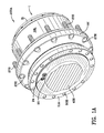
- Fig. 1 is a perspective view 100 of the planetary gearbox with integral service brake 1.
- Reference numeral 1 is used to denote the planetary gearbox with integral service brake.
- End cover 31 is illustrated on right end of the drawing. End cover 31 is affixed to and rotates with outer housing 19L. Oil fill and drain holes 30 are illustrated in the cover 31.
- the outer housing 19L is referred to as a hub.
- Intermediate hub 19I is affixed to outer ting hear housing by threaded studs 27S and/or by other connectors.
- Bearing support 11 M is illustrated in Fig. 2 and is affixed to the stationary spindle 11 A. Threaded studs 27S are used to affix a wheel of a vehicle to the planetary gearbox.
- Holes 50H are illustrated in stationary spindle 11A which is bolted to the frame of the vehicle.
- Fig. 1A is another perspective view 100A of the planetary gearbox with integral service brake 1.
- Motor shaft 40S inputs power and rotary motion into the gearbox 1.
- Pressure supply ports 20, 24 are illustrated in Fig. 1A .
- Pressure supply port 20 is connected with passageway 20P which supplies pressure to a parking brake cavity 17N. See Fig. 2 and 2B which illustrate the parking brake in the actuated position which is the normal, safe position.
- Pressure is applied in passageway 20 and in parking brake cavity 17N and acts upon piston 17A releasing the parking brake and enabling operation of the wheel and, hence, the vehicle.
- Pressure is preferably applied using hydraulic fluid, however, air pressure or some other fluid may be used.
- pressure supply port 24 is connected with passageway 24P which supplies pressure to a service brake cavity 19N.
- Fig. 4 and 4A which illustrate the service brake 19 in the not actuated condition.
- the service brake 19 does not engage the service brake stack comprised of rotor discs 19C and stator discs 19D.
- Stator discs 19D include protrusions 53 which reside in corresponding grooves 51 G which reside in the exterior of the stationary spindle 11A.
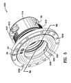
- Three portions of the spindle include alternating raised protrusions 51 P and grooves 51 G as set forth in Fig. 5 .
- the three portions of the spindle are separated by 120°. It will be understood by those skilled in the art that the spacing and grouping of these portions may be different. In this way, the stator discs 19D are fixed against rotation with respect to the spindle 11A.
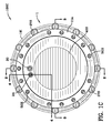
- Fig. 1B is a right end view 100B of the planetary gearbox with integral service brake 1. An oil fill level is indicated on the cover 31.
- Fig. 1C is a left end view 100C of the planetary gearbox with integral service brake 1.
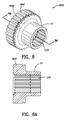
- Fig. 6 illustrates the service brake stator discs 19D and the service brake rotor discs 19C grouped together.
- Stator discs 19D include inner protrusions 53 for locking the stator discs to the stationary spindle 11A.
- Rotor discs 19C include protrusions 67 in the shape of a portion of a semi-circle.
- Fig. 2B is an enlargement 200B of a portion of Fig. 2 illustrating the parking brake 17.
- Spring 17D applies force to piston 17A which engages the parking brake stack.
- the parking brake stack includes a plurality of rotor discs 17B which are affixed to coupling 11.
- Coupling 11 is illustrated in Fig. 8 having a series of ridges or protrusions 80P to which rotor discs 17B are keyed.
- Rotor discs 17B include a series of recesses 81 G as illustrated in Fig. 7 which interfit ridges/protrusions 80P of the coupling.
- friction material 17Z is illustrated on the rotor discs 17B.
- the friction material is a sintered bronze type.
- the friction material 17Z can be on either the stator discs 17C or the rotor discs 17B. Still referring to Fig. 2B , spring 17D operates against plate 17L which is fixed by ring 17K.
- Seals 17G and 17J are preferably elastomeric seals and are located in unnumbered recesses in stationary spindle 11A. Seals 17G, 17J are adjacent parking brake cavity 17N and seal parking brake cavity 17N.
- Stators 17C include protrusions 66 which are keyed to recesses 55 in spindle 11A to prevent rotation of the stators 17C with respect to the spindle 11A. See Fig. 3A , 3B , and 7 which illustrate the protrusion 66. See Fig. 3A and 5A which illustrate recesses 55.
- Fig. 6 is a perspective view 600 of the stator 19D and rotor 19C brake discs of the service brake stack. Protrusions 66 of the stators 17C of the parking brake 17 are illustrated in Fig. 7 . Protrusions 66 mate with recesses 55 of the stationary spindle 11A as illustrated in Fig. 5A .
- Fig. 6A is an enlarged cross-sectional view 600A of the service brake stack taken along the lines 6A-6A of Fig. 6 .
- FIG. 5B is a perspective view 500B of intermediate hub 19I.
- Friction material 19Z is illustrated in Fig. 2A and 6A on rotor disc 19C.
- the friction material is a sintered bronze type. Other friction materials may be used.
- Fig. 6 and 6A illustrate generally spiral shaped slits 19X in the friction material 19Z.
- Fig. 6A also illustrates generally radially shaped slits 19R in the friction material 19Z.
- Slits 19X and 19R permit lubricating oil to flow therein enabling improved heat transfer.
- Spirally shaped slits 19X allow lubricating oil to flow from the inner portion of the spiral to the outer portion of the spiral.
- the spiral nature of the slits 19X allows lubricating oil to move more efficiently and more slowly across the side of the rotor disc thus improving heat transfer.
- Radial slits 19R allow lubricating oil to move radially outwardly along the slits 19R.
- Rotor discs 19C and stator discs 19D are illustrated in Fig. 6A as being in engagement with one another.
- Portions of the brake parts, the stationary spindle, the gearing, the disconnect plug, and the coupling are made of carbon steel. Other suitable materials may be used.
- the housings/hubs, cover, and input carrier are made of ductile iron. Other suitable materials may be used.
- Lubrication as described above in connection with slits 19X and 19R occurs when the stator discs 19D and the rotor discs 19C are separated.
- First and second oil passageways 22 in the stationary spindle are located horizontally with respect to the earth just above the oil fill level. However, additional oil passageways could be located within the stationary spindle 11 A and be oriented differently with respect to the earth.
- the parking brake stator discs 17C and rotor discs 17B are separated each from the other. As the rotor discs 17B rotate with the coupling 11, they pick-up oil and move the oil into first and second oil passageways 22 in the stationary spindle 11A.
- Fig. 2 is a cross-sectional view 200 taken along the lines 2-2 of Fig. 1C illustrating the service brake 19 and the parking brake 17, and port 20 and passageway 20P supplying pressure to the parking brake piston cavity 17N operating the parking brake piston 17A. See Fig. 2B which shows the parking brake in detail.
- Fig. 2A is an enlargement 200A of a portion of Fig. 2 illustrating the service brake 19.
- the service brake is not actuated, in other words, no pressure has been applied to the service brake piston cavity 19N.
- the service brake piston cavity 19N is best illustrated in Fig. 4A .
- Fig. 5B is a perspective view 500B of the intermediate hub 19I illustrating recesses 65 for engagement with protrusions 67 of the rotor discs 19C of the service brake 19.
- Fig. 2 includes an illustration of the planetary gear system which includes an input stage and an output stage.
- the input stage is illustrated and includes the input shaft 6S, sun gear 6, input planet gears 10F, input ring gear 7, and input carrier 10A.
- Input carrier 10A drives the output stage of the planetary gear system.
- Input carrier 10A drives the second/output sun gear 10H which drives the output planet gears 11 H which mesh with output housing 19L.
- Fig. 4 is a cross-sectional view 400 of the planetary gearbox with integral service brake 1 taken along the lines 4-4 of Fig. 1C illustrating, inter alia, port 24 and a passageway 24P supplying the service brake piston cavity 19N operating the service brake piston 19B.
- Fig. 4A is an enlargement 400A of a portion of Fig. 4 illustrating the service brake 19, the service brake piston 19B, the parking brake 17, and the parking brake piston 17A.
- Fig. 4 and 4A illustrate the service brake 19 in the normal state which is the "off" condition, or the non-actuated position, or put another way, the disengaged position.
- the rotor discs 19C and the stator discs 19D are illustrated in Fig. 4A and they are not in engagement with each other.
- Spring 19F is a wave spring and it encircles the stationary spindle 11 A.
- Spring 19F urges service brake piston 19B away from the service brake disc stack.
- service brake disc stack it is meant the rotors 19C and the stators 19D.
- O-ring seals 19J, 19K seal the sealing ring 19A.
- O-rings 19K, 19K seal the opening leading to the service brake piston cavity 19N as best viewed in Fig. 4A .
- protrusions 53 of stator discs 19D are shown and these protrusions reside in one of the grooves 51 G of the stationary spindle 11A.
- Service brake piston cavity 19N is formed between sealing ring 19A, service brake piston 19B and the stationary spindle 11A.
- Retaining ring 19E retains thrust washer 19G and wave return spring 19F.
- the service brake 19 normally operates in the disengaged state except when the operator of the vehicle wants to slow or stop the vehicle. In the position illustrated in Fig. 4 and 4A , the vehicle is parked as the parking brake 17 is engaged and the service brake piston is shown engaging the brake stack.
- Fig. 4 and 4A also illustrate the intermediate hub 19I affixed to the rotatable housing 19L.
- Fig. 4B is an enlarged view 400B similar to the enlargement of Fig. 4A illustrating the parking brake 17 not actuated and the service brake 19 actuated with pressure being applied to the service brake piston cavity 19N.
- the vehicle is stopped or slowing and the parking brake has been released and is not activated or engaged and pressure has been applied to parking brake piston cavity 17N.
- Fig. 5 is a perspective view 500 of the spindle 11A illustrating exterior ridges or protrusions 51 P and grooves 51 G between the protrusions.
- the protrusions 51 P and grooves 51 G prevent rotation of the stator discs 19D operating between the stationary spindle 11A and the rotatable intermediate hub 19I.
- FIG. 5A is a cross-sectional view 500A taken along the lines 5A-5A of Fig. 5 illustrating the oil return passageways 22A, 22B, and 22C in the spindle 11A.
- Fig. 5B is a perspective view 500B of the intermediate hub 19I illustrating recesses 65 for engagement with protrusions 67 of the rotor discs 19C of the service brake 19.
- Fig. 2 is a cross-sectional view 200 taken along the lines 2-2 of Fig. 1C illustrating the service brake 19 and the parking brake 17, and port 20 and a passageway 20P for supplying pressure to the parking brake piston cavity 17N operating the parking brake piston 17A.
- Fig. 2 there is not pressure in cavity 17N. See Fig. 2B for an enlarged view.
- Fig 2 illustrates the motor drive shaft 40S which is supported by bearings or some other support system not illustrated herein. Motor shaft 40S is splined to coupling 11.
- Fig. 8 illustrates coupling 11, internal spline 11 S, and exterior protrusions 80P and exterior grooves 80G. The exterior protrusions 80P and grooves 80G are in a mating arrangement with the rotor discs 17B of the parking brake 17.
- Parking brake 17 is illustrated best in Fig. 2B and 3A .
- Spindle 11A includes flange 50 and bolt holes 50H in the flange for securing the spindle to the frame of the vehicle.
- Seal 11 B resides intermediate spindle 11A and intermediate hub 19I and prevents dust and debris from entering bearing 11C and other components.
- Intermediate hub 19I is illustrated in Fig. 5B and illustrates recesses 65 which receive correspondingly shaped protrusions 67 of the rotor discs of the service brake 19 which interfit the recesses 65. In this way, rotors 19C rotate with hubs 19I, 19L.
- Studs 27S affix intermediate hub 19I to output housing 19L. Additionally, studs 27S interconnect the wheel of the vehicle to the intermediate hub 19I and to the output housing 19L.
- Service brake piston 19B is viewed in Fig. 2 and is best viewed in Fig. 2A .
- Output ring gear 5 is splined 23S to output housing 19L.
- Output planet gears 11 H are supported by output planet shaft 11 N which is mounted in the stationary spindle 11 A.
- Bearing carrier/support 11 M is affixed to the stationary spindle 11A with bolts (not shown) and secures the rotatable components of the planetary gearbox and integral service brake to the stationary spindle enabling them to rotate therearound.
- output planet thrust washers 11 J, 11K secure the output planet gear 11 H for controlled rotation about output stage needle bearings 11 R and output planet shaft 11N.
- Bolts 35 secure the cover 31 to the output gear housing 19L.
- Fig. 2 illustrates the input shaft 6S splined to coupling 11.
- Input planet gears 10F are mounted about input planet shaft 10D on needle bearing 10C.
- Input planet shaft 10D is mounted to input planet carrier 10A and the input planet gears 10F rotate therearound.
- Input shaft 6S includes a first sun gear 6 in meshing engagement 39M with input planet gears 10F.
- Input planet gears 10F are in meshing engagement with input ring gear 7 and react thereto driving carrier 10A.
- Input ring gear 7 is splined 25S to cover 31.
- Fig. 2 also illustrates cover 31 and several oil fill or drain plugs therein 30. Retaining ring 32 secures the disconnect plug 34 and O-ring 33.
- roll pin 10E secures the input planet shaft 10D to the input planet carrier 10A.
- Retaining ring 10G secures the input planet carrier 10A to the output sun gear 10H.
- Input planet carrier 10A is splined 10X to output sun gear 10H and the output sun gear rotates therewith.
- Thrust washers 10B secure the needle bearings 10C to shaft 10D.
- Output sun gear 10H is in meshing engagement 37M with output planet gears11H.
- Output planet gears do not orbit within the gearbox, rather, they are mounted on output planet shafts 11 N and corresponding needle bearings 11 R.
- Output planet gears 11 H mesh with the output ring gear 5 which is splined 23S to the output housing.
- Output planet gears 11 H drive output housing 19L and intermediate hub 19I.
- Fig. 7 is an enlarged perspective view 700 of the parking brake stack 17. Protrusions 66 which mate with recesses 55 in the stationary spindle 11A are illustrated in Fig. 7. Fig. 7 further illustrates protrusions 81 P and grooves 81 G which interfit with grooves 80G and protrusions 80P, respectively.
- Fig. 7A is an enlarged cross-sectional view 700A of the service brake stack taken along the lines 7A-7A of Fig. 7 .
- Stator discs 17C and rotor discs 17B are illustrated in Fig. 7A along with the friction material 17Z on the rotor discs 17B.
- the friction material 17Z can be on either the stator discs 17C or on the rotor discs 17B.
- Spiral shaped slits 17X are included in the rotor discs 17B.
- Radial slits 17R are also in the rotor disc 17B.
- Fig. 8 is a perspective view 800 of the coupling 11.
- Fig. 8 illustrates an internal spline 11 S to which input shaft 6S is connected and to which motor shaft 40S is connected.
- Fig. 8A is a cross-sectional view taken along the lines 8A-8A of Fig. 8 illustrating grooves 80G and protrusions 80P in the exterior thereof.
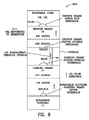
- Fig. 9 is a diagrammatic view 900 of the parking brake 17 and the service brake 19 together with the stationary spindle 11 A, the rotatable coupling 11 and the rotatable hubs 19I, 19L.
- This diagrammatic view is taken in consideration of the condition illustrated in Fig. 3B where both the service brake 19 and the parking brake 17 are not actuated and their respective disc stacks are not engaged.
- oil flow outwardly is represented by the unnumbered arrows in Fig. 9 .
- Rotatable coupling 11 includes ridges or protrusions 80P and grooves 80G as shown in Fig. 8 .
- Protrusions 80P interfit corresponding grooves 81 G of the rotor discs 17B of the parking brake 17 as shown in Fig. 7 .
- Parking brake stator discs 17C include protrusions 66 which interfit recesses 55 in the stationary spindle 11A as shown in Fig. 5A and 7 .
- Service brake stator discs 19D include protrusions 53 which interfit grooves 51 G of the stationary spindle 11A as shown in Fig. 5 and 6 .
- Passageways 22 transport oil through the stationary spindle 11 A.
- Service brake rotor discs 19C include protrusions 67 which interfit grooves 65 in rotatable hub 19I as shown in Fig. 5B and 6 .
- Oil exits along a passageway at the interface between the service brake 19 and the rotatable hub 19I to bearing 11C where it is pumped by the bearing to an oil return passageway into the oil reservoir as shown in Fig. 2 .
- the oil reservoir extends from the bottom of the gearbox to approximately the oil fill line.
- a double planetary gearbox with an output rotatable housing 19L is disclosed in the various drawing views.
- This type of gearbox operates by taking a rotational input from the motor shaft 40S.
- the shaft 40S is driven by a motor (not shown) and is coupled to the coupling 11.
- the coupling 11 is coupled to the input shaft 6S.
- the input shaft 6S includes a sun gear 6.
- the motion of the sun gear 6 is transmitted through an input planetary stage having input planet gears 10F and an output planetary stage having output planet gears 11 H.
- These planetary stages transmit motion to the ring gears 5, 7 which are rigidly connected to the intermediate hub 19I and the housing 19L.
- the intermediate hub 19I and the housing 19L are affixed together.
- the vehicle's wheel is attached to the intermediate hub 19I and the housing 19L.
- the output speed is reduced and the output torque is increased by the same ratio.
- the service brake is housed between the spindle 11 A which is connected to the frame of the vehicle and the intermediate hub 19I.
- the wheel of the vehicle is connected to the intermediate hub 19I by threaded studs 27S and nuts.
- One of the main wheel bearings 11C is mounted on the outer part of the spindle 11A and supports the intermediate hub 19I.
- Another main wheel bearing 11C is mounted between bearing support 11 M and output housing 19L.
- Output housing 19L is bolted to intermediate hub 19I. Both bearings 11C, 11C support the intermediate hub 19L and ring gear output housing 19L. Since the wheel of the vehicle is rigidly attached to the intermediate hub 19I by the studs 27S and nuts, the main wheel bearings 11C, 11C support any loading imparted to wheel of the vehicle.
- the service brake includes: a plurality of stators 19D; a plurality of rotors 19C; a service piston 19B; a service piston return spring 19F; and, a sealing ring 19A.
- the parking brake includes: a plurality of stators 17C; a plurality of rotors 17B; a parking piston 17A; and, a plurality of piston application springs17D.
- Springs 17D apply force to the parking piston 17A which in turn applies a force to a stack of alternating rotors 17B and stators 17C.
- the stators 17C are coupled to the spindle 11A and the rotors 17B are coupled to the coupling 11.
- Friction material can be on either the rotor 17B or stator 17C. This material is specially designed to prevent relative motion between the rotor and stator surfaces when a force is applied to the combination of alternating stators and rotors. By preventing motion between the rotors and stators, the coupling 11 is locked to the spindle 11A which prevents any motion from taking place in the planetary wheel drive.
- hydraulic charge pressure is applied to the parking release port 20.
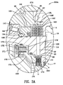
- Fig. 3 is a cross-sectional view 300 of the planetary gearbox with integral service brake 1 taken along the lines 3-3 of Fig. 1C illustrating, inter alia, radial oil passageways 22 in the stationary spindle 11A interconnecting the parking brake 17 and the service brake 19. As illustrated there are two oil passageways 22 in the stationary spindle. Oil passageways 22 are referred to as the first and second oil passageways.
- Lubricated spinning objects naturally pump oil from their inside diameter to their outside diameter due to the force imparted on the fluid. The same happens within wet disc brakes.
- the parking brake 17 pumps oil from its inside diameter to its outside diameter.
- the oil is pumped to the outside diameter of the parking brake disc pack it travels through oil passageways 22 and supplies lubricant/oil to the service brake and heat is removed from the service brake 19.
- Third oil passageway 26 leads from the service brake 19 to the left most bearing 11C in Fig. 2 . Also see the much larger fourth oil passageways 26A in Fig. 5B for supplying oil directly to the left most bearing 11C.
- Fourth oil passageways 26A comprises wide arc-shaped recesses in the intermediate hub 19I which supply lubricating oil directly to the left most bearing 11C.
- Third oil passageway 26 is supplied with oil from the rotor discs 19C of the service brake 19.
- Fourth oil passageways 26A are illustrated in Fig. 5B .
- Two fourth oil passageways 26A are illustrated in Fig. 5B .
- Left most bearing 11C in Fig. 2 pumps oil to oil return passageways 22A, 22B and 22C illustrated in Fig. 5A allowing oil to escape the service brake disc stack 19C, 19D to minimize parasitic losses that generate heat.
- Additional first and second oil passageways 22 through the stationary spindle above the oil line may be added.
- the parking brake 17 is actuated and no lubricating oil is being supplied to the first and second oil passageways 22 in the stationary spindle.
- Fig. 3A is an enlargement 300A of a portion of Fig. 3 illustrating the parking and service brake and a radial oil passageway 22 interconnecting the parking brake and the service brake.
- Fig. 3B is a view similar to Fig. 3A except that the parking brake is not engaged and, thus, the parking brake 17 is supplying oil through the stationary spindle to the service brake 19 and when the vehicle is running.
- the rotor 19C at the end of the disc stack is trapped between the housing 19L and the intermediate hub 19I.
- Protrusions 66 in the rotor 19C at the end of the disc stack is interconnected to intermediate hub 19I via recesses 68 in the intermediate hub 19I. See Fig. 5B illustrating recesses 68 which are slightly out of phase with recesses 65 (for example, not aligned with recesses 65). This prevents the service brake 19 disc pack from being slightly engaged when running clearances are reduced as oil is pumped against the last rotor 19C in the disc stack from adjacent gear meshes 36M.
- the machine operator When service braking is required, the machine operator will press his or her foot onto the brake pedal.
- the pedal is interlocked to the hydrostatic system which creates a negative torque at the motor shaft to begin slowing down the vehicle.
- pressure is delivered to the service brake port 24. The pressure will depend on how far the brake pedal is pushed down by the operator's foot.
- the service brake port delivers pressure to the service brake cavity 19N. Due to the pressure, the service piston moves and imparts a force on the rotors 19C and stators 19D.
- the invention utilizes discs with very large inner and outer diameters that are capable of absorbing heat so that the temperature in the brake cavity does not reach a destructive level.
- the service brake 19 since the service brake 19 is located radially outwardly from the common axis of the planetary gearbox, the circumference of the service brake 19 is large. Put another way, the service brake is adjacent to and engages the hub 19I. This location maximizes the size of the brake for a given thickness as measured from the inside diameter to the outside diameter of the disc stack (rotor discs and stator discs).
- the service brake enjoys a substantially reduction in angular velocity due to the large reduction of the planetary gearbox. Still additionally, since the service brake 19 is located radially outwardly from the common axis of the planetary gearbox, a considerable portion of the service brake is located below the oil line.
- Fig. 1 illustrates the preferred oil line on cover 31.
- the geometry of this assembly provides several advantages.
- First the service brake is packaged between the main bearing 11C and output planet gear 11 H in such a way that limits/prevents any effect of the overall length of the planetary gearbox assembly.
- the gearbox geometry also takes advantage of the natural tendency of the parking brake to pump oil to cool the service brake.
- the service brake solves the problems associated with external output brakes and internal input/intermediate multi-disc wet brakes that were previously mentioned.
Landscapes
- Engineering & Computer Science (AREA)
- Mechanical Engineering (AREA)
- General Engineering & Computer Science (AREA)
- Transportation (AREA)
- Chemical & Material Sciences (AREA)
- Combustion & Propulsion (AREA)
- Braking Arrangements (AREA)
- General Details Of Gearings (AREA)
Applications Claiming Priority (1)
| Application Number | Priority Date | Filing Date | Title |
|---|---|---|---|
| US14/184,472 US9429227B2 (en) | 2014-02-19 | 2014-02-19 | Planetary gearbox with integral service brake |
Publications (3)
| Publication Number | Publication Date |
|---|---|
| EP2910395A2 true EP2910395A2 (fr) | 2015-08-26 |
| EP2910395A3 EP2910395A3 (fr) | 2015-11-04 |
| EP2910395B1 EP2910395B1 (fr) | 2019-02-13 |
Family
ID=52102420
Family Applications (1)
| Application Number | Title | Priority Date | Filing Date |
|---|---|---|---|
| EP14195417.2A Active EP2910395B1 (fr) | 2014-02-19 | 2014-11-28 | Engrenage planétaire solidaire d'un frein de service intégral |
Country Status (4)
| Country | Link |
|---|---|
| US (1) | US9429227B2 (fr) |
| EP (1) | EP2910395B1 (fr) |
| DK (1) | DK2910395T3 (fr) |
| TR (1) | TR201905666T4 (fr) |
Cited By (4)
| Publication number | Priority date | Publication date | Assignee | Title |
|---|---|---|---|---|
| CN105090450A (zh) * | 2015-09-09 | 2015-11-25 | 黄安民 | 轮毂减速器 |
| WO2016139600A1 (fr) * | 2015-03-02 | 2016-09-09 | Bonfiglioli Riduttori S.P.A. | Appareil de freinage pour un essieu d'un véhicule électrique |
| WO2023031194A1 (fr) * | 2021-08-30 | 2023-03-09 | Zf Friedrichshafen Ag | Véhicule électrique doté d'au moins un système de freinage et procédé de fonctionnement d'un véhicule électrique |
| EP4212375A1 (fr) * | 2022-01-14 | 2023-07-19 | Rögelberg Holding GmbH & Co. KG | Transmission pour chaîne cinématique pour un véhicule agricole ou lourd ainsi que chaîne cinématique et véhicule correspondants |
Families Citing this family (15)
| Publication number | Priority date | Publication date | Assignee | Title |
|---|---|---|---|---|
| CA2915896C (fr) * | 2015-01-13 | 2021-08-03 | Rolls-Royce Corporation | Revetement de surface de friction de frein a cone |
| US10107363B2 (en) * | 2016-01-28 | 2018-10-23 | Deere & Company | Compact multi-speed planetary drive assembly |
| USD807260S1 (en) * | 2016-04-11 | 2018-01-09 | Christopher Mark Young | Brake conversion hub |
| USD783474S1 (en) * | 2016-04-28 | 2017-04-11 | Ausco Products, Inc. | Brake |
| US10495185B2 (en) | 2017-03-06 | 2019-12-03 | Fairfield Manufacturing Company, Inc. | Planetary wheel drive using bushings |
| US10272773B2 (en) * | 2017-03-06 | 2019-04-30 | Fairfield Manufacturing Company, Inc. | Planetary wheel drive using thrust washer—cover arrangement |
| US10132372B2 (en) | 2017-03-06 | 2018-11-20 | Fairfield Manufacturing Company, Inc. | Planetary wheel drive brake |
| US10066735B1 (en) | 2017-03-06 | 2018-09-04 | Fairfield Manufacturing Company, Inc. | Planetary wheel drive single wall lugged output carrier |
| US10093177B2 (en) | 2017-03-06 | 2018-10-09 | Fairfield Manufacturing Company, Inc. | Compact planetary wheel drive |
| JP2020529559A (ja) * | 2017-07-26 | 2020-10-08 | カーライル・ブレーキ・アンド・フリクション・インコーポレイテッド | 鉱業トラックのためのブレーキシステム |
| CN108426024A (zh) * | 2018-02-11 | 2018-08-21 | 意宁液压股份有限公司 | 动态制动器与行星减速器集成一体的传动装置 |
| DE102018109569A1 (de) * | 2018-04-20 | 2019-10-24 | Stabilus Gmbh | Bremsmodul für ein antriebssystem, antriebssystem und herstellungsverfahren für ein bremsmodul |
| US11498410B2 (en) * | 2019-10-23 | 2022-11-15 | Deere & Company | Powered axle for dual wheel work vehicle |
| US20220234727A1 (en) * | 2021-01-22 | 2022-07-28 | Safran Landing Systems | Brake assembly with contained brake environment |
| JP2023112389A (ja) * | 2022-02-01 | 2023-08-14 | 株式会社不二越 | フリーホイール機構付き遊星歯車機構 |
Family Cites Families (76)
| Publication number | Priority date | Publication date | Assignee | Title |
|---|---|---|---|---|
| US3998295A (en) | 1969-08-12 | 1976-12-21 | Martin Thomas C | Brake structure and adjusting device therefor |
| US4010830A (en) | 1975-04-11 | 1977-03-08 | Pettibone Corporation | Planetary wheel drive with accessible low-torque disc brakes |
| US4064973A (en) | 1976-11-18 | 1977-12-27 | The Bendix Corporation | Actuating and adjusting mechanism for disc brakes |
| US4279330A (en) | 1977-06-27 | 1981-07-21 | Walter Kidde & Company, Inc. | Double-acting disc brake |
| US4173269A (en) | 1978-02-23 | 1979-11-06 | Clark Equipment Company | Wet brake or clutch |
| FR2535258A1 (fr) | 1982-11-03 | 1984-05-04 | Soma Europ Transmissions | Moyeu de roue a frein et reducteur integres |
| US4498560A (en) | 1983-02-28 | 1985-02-12 | Purdy Ronald R | Emergency stopping brake system for tractors and trailers |
| US4742895A (en) | 1984-07-02 | 1988-05-10 | The B. F. Goodrich Company | Disk brake assembly |
| US4798269A (en) | 1986-08-06 | 1989-01-17 | Pt Components, Inc. | Direct lever acting solenoid released brake mechanism |
| FR2624232B1 (fr) | 1987-12-04 | 1991-11-22 | Elf France | Dispositif de freinage d'un element rotatif |
| US4845468A (en) | 1988-01-21 | 1989-07-04 | Dresser Industries, Inc. | Brake condition warning system |
| CA1328896C (fr) | 1988-02-12 | 1994-04-26 | Paul J. Middelhoven | Dispositif de freinage de roue a securite intrinseque |
| US4890699A (en) | 1988-07-28 | 1990-01-02 | The B. F. Goodrich Company | Wet disc friction brake with casing rods extending through stator bores |
| US5174420A (en) | 1991-05-02 | 1992-12-29 | Clark Equipment Company | Wet disc brake |
| US5228543A (en) | 1992-02-03 | 1993-07-20 | Power Transmission Technology, Inc. | Sealed wet disc brake for vehicles |
| US5253735A (en) | 1992-09-28 | 1993-10-19 | Larson Reese G | Apparatus to sense and annunciate truck brake condition |
| EP0636814B1 (fr) * | 1993-07-30 | 1997-09-03 | Oddone Vanzini | yransmission mécanique pour roues motrices, en particulier pour engin de travail mobile |
| US5601160A (en) | 1994-10-20 | 1997-02-11 | Case Corporation | Hydraulically actuated brake assembly for an off-highway implement |
| US5551534A (en) | 1995-06-05 | 1996-09-03 | Aircraft Braking Systems Corp. | Pressure balanced brake stack |
| US5685398A (en) | 1996-06-28 | 1997-11-11 | Rexnord Corporation | Fast response adjustable brake |
| US6019199A (en) | 1997-05-19 | 2000-02-01 | Power Transmission Technology, Inc. | Hydraulic caliper disk brake for steel mill cranes |
| JP3894627B2 (ja) | 1997-09-11 | 2007-03-22 | 本田技研工業株式会社 | 車両用多板式ブレーキ |
| IT1296239B1 (it) * | 1997-10-22 | 1999-06-18 | Carraro Spa | Gruppo integrato per la frenatura di stazionamento e di servizio di organi rotanti. |
| SE520017C2 (sv) | 1997-10-31 | 2003-05-06 | Mecman Ab Rexroth | Tryckfluidcylinder |
| SE510723C2 (sv) | 1997-10-31 | 1999-06-14 | Mecman Ab Rexroth | Tryckfluidcylinder |
| US6145635A (en) | 1998-06-23 | 2000-11-14 | White Hydraulics Inc. | Spring brake |
| US6170616B1 (en) | 1998-06-23 | 2001-01-09 | White Hydraulics Inc | Brake reaction pin |
| CA2336302A1 (fr) | 1998-07-01 | 2000-01-13 | Martin Kammerer | Systeme de commande hydraulique |
| US6116383A (en) | 1998-10-21 | 2000-09-12 | Meritor Heavy Vehicle Systems, Llc | Wet disc pack with variable co-efficients of friction discs |
| US6142262A (en) | 1998-10-21 | 2000-11-07 | Meritor Heavy Vehicle Systems, Llc | Wet disc pack with modified stationary discs |
| US6260668B1 (en) | 1999-04-29 | 2001-07-17 | Highland Machinery Corporation | Brake system for electrically powered vehicles |
| US6123019A (en) | 1999-05-05 | 2000-09-26 | The Minster Machine Company | Wet-type flywheel brake integrated into oil film quill |
| US6264009B1 (en) | 1999-06-03 | 2001-07-24 | Meritor Heavy Vehicle Systems, Llc | Multi-stage wet disc brake |
| US6508336B1 (en) | 2000-02-04 | 2003-01-21 | Meritor Heavy Vehicle Systems, Llc | Reduced drag wet disc brake assembly |
| JP4560873B2 (ja) | 2000-03-21 | 2010-10-13 | いすゞ自動車株式会社 | カウンタシャフトブレーキの潤滑装置 |
| US6543596B2 (en) | 2000-04-24 | 2003-04-08 | Borgwarner, Inc. | Multi-disk friction device having low-drag characteristics |
| FR2808853B1 (fr) | 2000-05-10 | 2002-08-02 | Poclain Hydraulics Ind | Systeme de freinage d'un rotor par rapport a un stator |
| DE10030441A1 (de) | 2000-06-22 | 2002-01-10 | Lohmann & Stolterfoht Gmbh | Radantrieb mit integrierter dynamischer Betriebsbremse |
| SE521910C2 (sv) | 2000-07-12 | 2003-12-16 | Volvo Constr Equip Components | Uppsättning av våta bromsar och fordon med nämnda bromsuppsättning |
| CN1454297A (zh) | 2000-08-01 | 2003-11-05 | 安全有效技术国际有限公司 | 湿式制动系统 |
| ATE344402T1 (de) | 2000-08-17 | 2006-11-15 | Knorr Bremse Systeme | Scheibenbremse mit einem zuspannsystem mit drehhebel |
| DE10055261A1 (de) | 2000-11-08 | 2002-05-23 | Linde Ag | Hydrostatische Axialkolbenmaschine in Schrägscheibenbauweise |
| US6481542B2 (en) | 2001-02-19 | 2002-11-19 | Meritor Heavy Vehicle Systems, Llc. | Brake adjuster |
| FR2826418B1 (fr) | 2001-06-21 | 2005-01-28 | Bosch Gmbh Robert | Frein a disque pour vehicule a convertisseur de mouvement |
| US6550588B2 (en) | 2001-07-10 | 2003-04-22 | Caterpillar Inc | Off highway truck brake assembly and wheel spindle having a spline joint |
| ATE323836T1 (de) | 2001-11-28 | 2006-05-15 | Bosch Rexroth Ag | Antrieb |
| DE10217631A1 (de) | 2002-04-19 | 2004-03-04 | Bosch Rexroth Ag | Bremssystem |
| FR2844563A1 (fr) | 2002-05-30 | 2004-03-19 | Punjab Tractors Ltd | Systeme d'huile perfectionne pour l'alimentation en huile des freins humides d'un tracteur |
| JP2004092741A (ja) | 2002-08-30 | 2004-03-25 | Honda Motor Co Ltd | 電磁ブレーキ |
| DE10241979A1 (de) | 2002-09-11 | 2004-03-18 | Bosch Rexroth Ag | Hydrotransformator |
| US6772863B2 (en) | 2002-10-21 | 2004-08-10 | Sauer-Danfoss (Nordborg) A/S | Brake appliance for gerotor motors |
| US7942482B2 (en) | 2003-02-28 | 2011-05-17 | Bosch Rexroth Ag | Brake system |
| DE10329047A1 (de) | 2003-06-27 | 2005-01-20 | Lohmann & Stolterfoht Gmbh | Bremsanordnung, insbesondere für einen hydraulischen Radantrieb |
| DE10345712A1 (de) | 2003-10-01 | 2005-04-21 | Bosch Rexroth Ag | Druck-Einspeiseventil |
| DE10354959A1 (de) | 2003-11-25 | 2005-06-30 | Bosch Rexroth Ag | Hydraulische Steueranordnung für ein mobiles Arbeitsgerät |
| DE10354954A1 (de) | 2003-11-25 | 2005-06-30 | Bosch Rexroth Ag | Einspritzeinheit |
| DE10357374A1 (de) | 2003-12-09 | 2005-07-14 | Knorr-Bremse Systeme für Nutzfahrzeuge GmbH | Scheibenbremse, insbesondere mit elektromotorischer Nachstellvorrichtung, und Verfahren zur Ansteuerung derartiger Scheibenbremsen |
| DE102004027279B4 (de) | 2004-06-04 | 2012-10-04 | Bosch Rexroth Ag | Antriebseinheit für eine Spritzgieß- oder Spritzprägemaschine |
| DE102004045951B4 (de) | 2004-09-22 | 2008-02-28 | Knorr-Bremse Systeme für Nutzfahrzeuge GmbH | Verfahren zur Einstellung des Lüftspiels einer Scheibenbremse |
| DE102005011395A1 (de) | 2005-03-11 | 2006-09-14 | Bosch Rexroth Ag | Hydraulische Steueranordnung |
| JP2007002904A (ja) | 2005-06-23 | 2007-01-11 | Hitachi Ltd | 電動ブレーキ装置 |
| US7493992B2 (en) | 2005-08-15 | 2009-02-24 | Pt Tech., Inc. | Gearbox brake for mining machinery |
| US7556128B2 (en) | 2005-10-31 | 2009-07-07 | Warner Electric Technology Llc | Dual actuator friction brake assembly |
| DE102005060340A1 (de) | 2005-12-16 | 2007-06-21 | Bosch Rexroth Ag | Verfahren und Vorrichtung zum hydrostatischen Bremsen eines Fahrzeugs |
| DE102006048198A1 (de) | 2005-12-16 | 2007-07-12 | Bosch Rexroth Ag | Hydrostatischer Antrieb und Verfahren zum Abbremsen eines hydrostatischen Antriebs |
| DE102006010508A1 (de) | 2005-12-20 | 2007-08-09 | Robert Bosch Gmbh | Fahrzeug mit einem Antriebsmotor zum Antreiben eines Fahrantriebs und einer Arbeitshydraulik |
| DE102005060990A1 (de) | 2005-12-20 | 2007-06-28 | Bosch Rexroth Aktiengesellschaft | Antrieb und hydrostatische Kolbenmaschine mit Rückgewinnung von Bremsenergie |
| DE102006006583A1 (de) | 2005-12-20 | 2007-06-21 | Robert Bosch Gmbh | Antrieb mit Energierückgewinnung |
| DE102005061990A1 (de) | 2005-12-23 | 2007-07-05 | Bosch Rexroth Aktiengesellschaft | Antrieb mit Energierückgewinnungs- und Retarderfunktion |
| DE102005061991A1 (de) | 2005-12-23 | 2007-07-05 | Bosch Rexroth Aktiengesellschaft | Hydrostatischer Antrieb |
| KR101302514B1 (ko) | 2005-12-27 | 2013-09-02 | 두산산업차량 주식회사 | 지게차의 전륜 브레이크장치 설치구조 |
| US7900751B2 (en) | 2006-02-01 | 2011-03-08 | Honeywell International Inc. | Method and brake disc assembly to utilize worn refurbished brake material |
| EP1993866A1 (fr) | 2006-03-13 | 2008-11-26 | Bosch Rexroth AG | Entraînement mécano-hydraulique doté d'une transmission à dérivation de puissance |
| US7909147B1 (en) | 2007-02-14 | 2011-03-22 | Ausco Products, Inc. | Low drag failsafe brake |
| JP5450542B2 (ja) | 2011-09-12 | 2014-03-26 | 日立建機株式会社 | ダンプトラックの走行駆動装置 |
| US8662277B2 (en) | 2011-12-22 | 2014-03-04 | Fairfield Manufacturing Company, Inc. | Planetary gearbox with integral service brake |
-
2014
- 2014-02-19 US US14/184,472 patent/US9429227B2/en active Active
- 2014-11-28 TR TR2019/05666T patent/TR201905666T4/tr unknown
- 2014-11-28 DK DK14195417.2T patent/DK2910395T3/da active
- 2014-11-28 EP EP14195417.2A patent/EP2910395B1/fr active Active
Non-Patent Citations (1)
| Title |
|---|
| None |
Cited By (5)
| Publication number | Priority date | Publication date | Assignee | Title |
|---|---|---|---|---|
| WO2016139600A1 (fr) * | 2015-03-02 | 2016-09-09 | Bonfiglioli Riduttori S.P.A. | Appareil de freinage pour un essieu d'un véhicule électrique |
| CN105090450A (zh) * | 2015-09-09 | 2015-11-25 | 黄安民 | 轮毂减速器 |
| CN105090450B (zh) * | 2015-09-09 | 2017-06-27 | 黄安民 | 轮毂减速器 |
| WO2023031194A1 (fr) * | 2021-08-30 | 2023-03-09 | Zf Friedrichshafen Ag | Véhicule électrique doté d'au moins un système de freinage et procédé de fonctionnement d'un véhicule électrique |
| EP4212375A1 (fr) * | 2022-01-14 | 2023-07-19 | Rögelberg Holding GmbH & Co. KG | Transmission pour chaîne cinématique pour un véhicule agricole ou lourd ainsi que chaîne cinématique et véhicule correspondants |
Also Published As
| Publication number | Publication date |
|---|---|
| DK2910395T3 (da) | 2019-05-06 |
| EP2910395A3 (fr) | 2015-11-04 |
| US9429227B2 (en) | 2016-08-30 |
| EP2910395B1 (fr) | 2019-02-13 |
| TR201905666T4 (tr) | 2019-05-21 |
| US20150233467A1 (en) | 2015-08-20 |
Similar Documents
| Publication | Publication Date | Title |
|---|---|---|
| EP2910395B1 (fr) | Engrenage planétaire solidaire d'un frein de service intégral | |
| US8662277B2 (en) | Planetary gearbox with integral service brake | |
| US4736821A (en) | Fluid cooled friction brake | |
| JP6214652B2 (ja) | 回転するブレーキ解放ピストンを備えたモータ及びブレーキの複合機構 | |
| EP2607696B1 (fr) | Dispositif électro-hydraulique intégré | |
| CN103079860A (zh) | 混合系统 | |
| CN108811494B (zh) | 行星轮驱动器单壁凸耳式输出齿轮架 | |
| JP6665988B2 (ja) | ブッシングを用いた遊星歯車駆動装置 | |
| JP5123015B2 (ja) | 発電電動機 | |
| EP2875237B1 (fr) | Moteur hydraulique à roue libre | |
| KR20180040681A (ko) | 하이브리드 구동 시스템용 클러치 장치 | |
| CN102748432B (zh) | 一种减速机 | |
| AU2013237977B2 (en) | Lock-up clutch assembly having improved torque capacity | |
| CN113348102B (zh) | 混合驱动装置 | |
| US4576256A (en) | Wheel hub with built-in brake | |
| AU2013237977A1 (en) | Lock-up clutch assembly having improved torque capacity | |
| CN107091305B (zh) | 用于电动汽车的行星齿轮变速箱 | |
| US20120178574A1 (en) | Motor module assembly | |
| EP0076387A1 (fr) | Frein à friction à refroidissement par fluide | |
| JP6632729B2 (ja) | 遊星歯車駆動装置 | |
| CN111287762B (zh) | 特别是用于隧道掘进机或用于驱动齿圈的电动机-传动机构-单元 | |
| CN107054054B (zh) | 用于混合驱动装置的离合器装置 | |
| EP0124592A1 (fr) | Dispositif de couple hydraulique | |
| KR102519194B1 (ko) | 자동차용 슬립 제한형 차동 장치 및 이를 포함하는 전동 구동 장치 | |
| JP2015230092A (ja) | トランスアクスルの潤滑用油路 |
Legal Events
| Date | Code | Title | Description |
|---|---|---|---|
| PUAI | Public reference made under article 153(3) epc to a published international application that has entered the european phase |
Free format text: ORIGINAL CODE: 0009012 |
|
| AK | Designated contracting states |
Kind code of ref document: A2 Designated state(s): AL AT BE BG CH CY CZ DE DK EE ES FI FR GB GR HR HU IE IS IT LI LT LU LV MC MK MT NL NO PL PT RO RS SE SI SK SM TR |
|
| AX | Request for extension of the european patent |
Extension state: BA ME |
|
| PUAL | Search report despatched |
Free format text: ORIGINAL CODE: 0009013 |
|
| AK | Designated contracting states |
Kind code of ref document: A3 Designated state(s): AL AT BE BG CH CY CZ DE DK EE ES FI FR GB GR HR HU IE IS IT LI LT LU LV MC MK MT NL NO PL PT RO RS SE SI SK SM TR |
|
| AX | Request for extension of the european patent |
Extension state: BA ME |
|
| RIC1 | Information provided on ipc code assigned before grant |
Ipc: B60K 17/04 20060101ALI20151001BHEP Ipc: B60K 17/14 20060101AFI20151001BHEP |
|
| 17P | Request for examination filed |
Effective date: 20160422 |
|
| RBV | Designated contracting states (corrected) |
Designated state(s): AL AT BE BG CH CY CZ DE DK EE ES FI FR GB GR HR HU IE IS IT LI LT LU LV MC MK MT NL NO PL PT RO RS SE SI SK SM TR |
|
| RIN1 | Information on inventor provided before grant (corrected) |
Inventor name: NOERENBERG, RYAN L. |
|
| GRAP | Despatch of communication of intention to grant a patent |
Free format text: ORIGINAL CODE: EPIDOSNIGR1 |
|
| STAA | Information on the status of an ep patent application or granted ep patent |
Free format text: STATUS: GRANT OF PATENT IS INTENDED |
|
| INTG | Intention to grant announced |
Effective date: 20180529 |
|
| GRAJ | Information related to disapproval of communication of intention to grant by the applicant or resumption of examination proceedings by the epo deleted |
Free format text: ORIGINAL CODE: EPIDOSDIGR1 |
|
| STAA | Information on the status of an ep patent application or granted ep patent |
Free format text: STATUS: REQUEST FOR EXAMINATION WAS MADE |
|
| INTC | Intention to grant announced (deleted) | ||
| STAA | Information on the status of an ep patent application or granted ep patent |
Free format text: STATUS: EXAMINATION IS IN PROGRESS |
|
| 17Q | First examination report despatched |
Effective date: 20180917 |
|
| GRAS | Grant fee paid |
Free format text: ORIGINAL CODE: EPIDOSNIGR3 |
|
| STAA | Information on the status of an ep patent application or granted ep patent |
Free format text: STATUS: GRANT OF PATENT IS INTENDED |
|
| GRAP | Despatch of communication of intention to grant a patent |
Free format text: ORIGINAL CODE: EPIDOSNIGR1 |
|
| INTG | Intention to grant announced |
Effective date: 20181203 |
|
| RAP1 | Party data changed (applicant data changed or rights of an application transferred) |
Owner name: FAIRFIELD MANUFACTURING COMPANY, INC. |
|
| GRAA | (expected) grant |
Free format text: ORIGINAL CODE: 0009210 |
|
| STAA | Information on the status of an ep patent application or granted ep patent |
Free format text: STATUS: THE PATENT HAS BEEN GRANTED |
|
| AK | Designated contracting states |
Kind code of ref document: B1 Designated state(s): AL AT BE BG CH CY CZ DE DK EE ES FI FR GB GR HR HU IE IS IT LI LT LU LV MC MK MT NL NO PL PT RO RS SE SI SK SM TR |
|
| REG | Reference to a national code |
Ref country code: GB Ref legal event code: FG4D |
|
| REG | Reference to a national code |
Ref country code: CH Ref legal event code: EP Ref country code: AT Ref legal event code: REF Ref document number: 1095985 Country of ref document: AT Kind code of ref document: T Effective date: 20190215 |
|
| REG | Reference to a national code |
Ref country code: IE Ref legal event code: FG4D |
|
| REG | Reference to a national code |
Ref country code: DE Ref legal event code: R096 Ref document number: 602014040949 Country of ref document: DE |
|
| REG | Reference to a national code |
Ref country code: SE Ref legal event code: TRGR |
|
| REG | Reference to a national code |
Ref country code: DK Ref legal event code: T3 Effective date: 20190430 |
|
| REG | Reference to a national code |
Ref country code: DE Ref legal event code: R082 Ref document number: 602014040949 Country of ref document: DE Representative=s name: PFENNING, MEINIG & PARTNER MBB PATENTANWAELTE, DE |
|
| REG | Reference to a national code |
Ref country code: LT Ref legal event code: MG4D |
|
| REG | Reference to a national code |
Ref country code: NL Ref legal event code: MP Effective date: 20190213 |
|
| PG25 | Lapsed in a contracting state [announced via postgrant information from national office to epo] |
Ref country code: PT Free format text: LAPSE BECAUSE OF FAILURE TO SUBMIT A TRANSLATION OF THE DESCRIPTION OR TO PAY THE FEE WITHIN THE PRESCRIBED TIME-LIMIT Effective date: 20190613 Ref country code: NO Free format text: LAPSE BECAUSE OF FAILURE TO SUBMIT A TRANSLATION OF THE DESCRIPTION OR TO PAY THE FEE WITHIN THE PRESCRIBED TIME-LIMIT Effective date: 20190513 Ref country code: LT Free format text: LAPSE BECAUSE OF FAILURE TO SUBMIT A TRANSLATION OF THE DESCRIPTION OR TO PAY THE FEE WITHIN THE PRESCRIBED TIME-LIMIT Effective date: 20190213 Ref country code: NL Free format text: LAPSE BECAUSE OF FAILURE TO SUBMIT A TRANSLATION OF THE DESCRIPTION OR TO PAY THE FEE WITHIN THE PRESCRIBED TIME-LIMIT Effective date: 20190213 |
|
| PG25 | Lapsed in a contracting state [announced via postgrant information from national office to epo] |
Ref country code: GR Free format text: LAPSE BECAUSE OF FAILURE TO SUBMIT A TRANSLATION OF THE DESCRIPTION OR TO PAY THE FEE WITHIN THE PRESCRIBED TIME-LIMIT Effective date: 20190514 Ref country code: HR Free format text: LAPSE BECAUSE OF FAILURE TO SUBMIT A TRANSLATION OF THE DESCRIPTION OR TO PAY THE FEE WITHIN THE PRESCRIBED TIME-LIMIT Effective date: 20190213 Ref country code: BG Free format text: LAPSE BECAUSE OF FAILURE TO SUBMIT A TRANSLATION OF THE DESCRIPTION OR TO PAY THE FEE WITHIN THE PRESCRIBED TIME-LIMIT Effective date: 20190513 Ref country code: RS Free format text: LAPSE BECAUSE OF FAILURE TO SUBMIT A TRANSLATION OF THE DESCRIPTION OR TO PAY THE FEE WITHIN THE PRESCRIBED TIME-LIMIT Effective date: 20190213 Ref country code: IS Free format text: LAPSE BECAUSE OF FAILURE TO SUBMIT A TRANSLATION OF THE DESCRIPTION OR TO PAY THE FEE WITHIN THE PRESCRIBED TIME-LIMIT Effective date: 20190613 Ref country code: LV Free format text: LAPSE BECAUSE OF FAILURE TO SUBMIT A TRANSLATION OF THE DESCRIPTION OR TO PAY THE FEE WITHIN THE PRESCRIBED TIME-LIMIT Effective date: 20190213 |
|
| PG25 | Lapsed in a contracting state [announced via postgrant information from national office to epo] |
Ref country code: RO Free format text: LAPSE BECAUSE OF FAILURE TO SUBMIT A TRANSLATION OF THE DESCRIPTION OR TO PAY THE FEE WITHIN THE PRESCRIBED TIME-LIMIT Effective date: 20190213 Ref country code: SK Free format text: LAPSE BECAUSE OF FAILURE TO SUBMIT A TRANSLATION OF THE DESCRIPTION OR TO PAY THE FEE WITHIN THE PRESCRIBED TIME-LIMIT Effective date: 20190213 Ref country code: EE Free format text: LAPSE BECAUSE OF FAILURE TO SUBMIT A TRANSLATION OF THE DESCRIPTION OR TO PAY THE FEE WITHIN THE PRESCRIBED TIME-LIMIT Effective date: 20190213 Ref country code: ES Free format text: LAPSE BECAUSE OF FAILURE TO SUBMIT A TRANSLATION OF THE DESCRIPTION OR TO PAY THE FEE WITHIN THE PRESCRIBED TIME-LIMIT Effective date: 20190213 Ref country code: AL Free format text: LAPSE BECAUSE OF FAILURE TO SUBMIT A TRANSLATION OF THE DESCRIPTION OR TO PAY THE FEE WITHIN THE PRESCRIBED TIME-LIMIT Effective date: 20190213 Ref country code: CZ Free format text: LAPSE BECAUSE OF FAILURE TO SUBMIT A TRANSLATION OF THE DESCRIPTION OR TO PAY THE FEE WITHIN THE PRESCRIBED TIME-LIMIT Effective date: 20190213 |
|
| REG | Reference to a national code |
Ref country code: DE Ref legal event code: R097 Ref document number: 602014040949 Country of ref document: DE |
|
| PG25 | Lapsed in a contracting state [announced via postgrant information from national office to epo] |
Ref country code: PL Free format text: LAPSE BECAUSE OF FAILURE TO SUBMIT A TRANSLATION OF THE DESCRIPTION OR TO PAY THE FEE WITHIN THE PRESCRIBED TIME-LIMIT Effective date: 20190213 Ref country code: SM Free format text: LAPSE BECAUSE OF FAILURE TO SUBMIT A TRANSLATION OF THE DESCRIPTION OR TO PAY THE FEE WITHIN THE PRESCRIBED TIME-LIMIT Effective date: 20190213 |
|
| PLBE | No opposition filed within time limit |
Free format text: ORIGINAL CODE: 0009261 |
|
| STAA | Information on the status of an ep patent application or granted ep patent |
Free format text: STATUS: NO OPPOSITION FILED WITHIN TIME LIMIT |
|
| 26N | No opposition filed |
Effective date: 20191114 |
|
| PGFP | Annual fee paid to national office [announced via postgrant information from national office to epo] |
Ref country code: SE Payment date: 20191127 Year of fee payment: 6 Ref country code: FI Payment date: 20191127 Year of fee payment: 6 |
|
| PG25 | Lapsed in a contracting state [announced via postgrant information from national office to epo] |
Ref country code: SI Free format text: LAPSE BECAUSE OF FAILURE TO SUBMIT A TRANSLATION OF THE DESCRIPTION OR TO PAY THE FEE WITHIN THE PRESCRIBED TIME-LIMIT Effective date: 20190213 |
|
| PGFP | Annual fee paid to national office [announced via postgrant information from national office to epo] |
Ref country code: IT Payment date: 20191125 Year of fee payment: 6 Ref country code: FR Payment date: 20191125 Year of fee payment: 6 |
|
| PGFP | Annual fee paid to national office [announced via postgrant information from national office to epo] |
Ref country code: TR Payment date: 20191108 Year of fee payment: 6 |
|
| PGFP | Annual fee paid to national office [announced via postgrant information from national office to epo] |
Ref country code: GB Payment date: 20191127 Year of fee payment: 6 |
|
| REG | Reference to a national code |
Ref country code: CH Ref legal event code: PL |
|
| PG25 | Lapsed in a contracting state [announced via postgrant information from national office to epo] |
Ref country code: LU Free format text: LAPSE BECAUSE OF NON-PAYMENT OF DUE FEES Effective date: 20191128 Ref country code: LI Free format text: LAPSE BECAUSE OF NON-PAYMENT OF DUE FEES Effective date: 20191130 Ref country code: CH Free format text: LAPSE BECAUSE OF NON-PAYMENT OF DUE FEES Effective date: 20191130 Ref country code: MC Free format text: LAPSE BECAUSE OF FAILURE TO SUBMIT A TRANSLATION OF THE DESCRIPTION OR TO PAY THE FEE WITHIN THE PRESCRIBED TIME-LIMIT Effective date: 20190213 |
|
| PG25 | Lapsed in a contracting state [announced via postgrant information from national office to epo] |
Ref country code: IE Free format text: LAPSE BECAUSE OF NON-PAYMENT OF DUE FEES Effective date: 20191128 |
|
| REG | Reference to a national code |
Ref country code: AT Ref legal event code: UEP Ref document number: 1095985 Country of ref document: AT Kind code of ref document: T Effective date: 20190213 |
|
| PGFP | Annual fee paid to national office [announced via postgrant information from national office to epo] |
Ref country code: DK Payment date: 20201022 Year of fee payment: 7 Ref country code: AT Payment date: 20201022 Year of fee payment: 7 |
|
| PGFP | Annual fee paid to national office [announced via postgrant information from national office to epo] |
Ref country code: BE Payment date: 20201023 Year of fee payment: 7 |
|
| PG25 | Lapsed in a contracting state [announced via postgrant information from national office to epo] |
Ref country code: CY Free format text: LAPSE BECAUSE OF FAILURE TO SUBMIT A TRANSLATION OF THE DESCRIPTION OR TO PAY THE FEE WITHIN THE PRESCRIBED TIME-LIMIT Effective date: 20190213 |
|
| REG | Reference to a national code |
Ref country code: FI Ref legal event code: MAE |
|
| REG | Reference to a national code |
Ref country code: SE Ref legal event code: EUG |
|
| GBPC | Gb: european patent ceased through non-payment of renewal fee |
Effective date: 20201128 |
|
| PG25 | Lapsed in a contracting state [announced via postgrant information from national office to epo] |
Ref country code: MT Free format text: LAPSE BECAUSE OF FAILURE TO SUBMIT A TRANSLATION OF THE DESCRIPTION OR TO PAY THE FEE WITHIN THE PRESCRIBED TIME-LIMIT Effective date: 20190213 Ref country code: HU Free format text: LAPSE BECAUSE OF FAILURE TO SUBMIT A TRANSLATION OF THE DESCRIPTION OR TO PAY THE FEE WITHIN THE PRESCRIBED TIME-LIMIT; INVALID AB INITIO Effective date: 20141128 Ref country code: FI Free format text: LAPSE BECAUSE OF NON-PAYMENT OF DUE FEES Effective date: 20201128 |
|
| PG25 | Lapsed in a contracting state [announced via postgrant information from national office to epo] |
Ref country code: SE Free format text: LAPSE BECAUSE OF NON-PAYMENT OF DUE FEES Effective date: 20201129 |
|
| PG25 | Lapsed in a contracting state [announced via postgrant information from national office to epo] |
Ref country code: IT Free format text: LAPSE BECAUSE OF NON-PAYMENT OF DUE FEES Effective date: 20201128 Ref country code: FR Free format text: LAPSE BECAUSE OF NON-PAYMENT OF DUE FEES Effective date: 20201130 |
|
| PG25 | Lapsed in a contracting state [announced via postgrant information from national office to epo] |
Ref country code: GB Free format text: LAPSE BECAUSE OF NON-PAYMENT OF DUE FEES Effective date: 20201128 |
|
| REG | Reference to a national code |
Ref country code: DK Ref legal event code: EBP Effective date: 20211130 |
|
| PG25 | Lapsed in a contracting state [announced via postgrant information from national office to epo] |
Ref country code: TR Free format text: LAPSE BECAUSE OF NON-PAYMENT OF DUE FEES Effective date: 20201128 Ref country code: MK Free format text: LAPSE BECAUSE OF FAILURE TO SUBMIT A TRANSLATION OF THE DESCRIPTION OR TO PAY THE FEE WITHIN THE PRESCRIBED TIME-LIMIT Effective date: 20190213 |
|
| REG | Reference to a national code |
Ref country code: AT Ref legal event code: MM01 Ref document number: 1095985 Country of ref document: AT Kind code of ref document: T Effective date: 20211128 |
|
| PG25 | Lapsed in a contracting state [announced via postgrant information from national office to epo] |
Ref country code: BE Free format text: LAPSE BECAUSE OF NON-PAYMENT OF DUE FEES Effective date: 20211130 |
|
| REG | Reference to a national code |
Ref country code: BE Ref legal event code: MM Effective date: 20211130 |
|
| PG25 | Lapsed in a contracting state [announced via postgrant information from national office to epo] |
Ref country code: AT Free format text: LAPSE BECAUSE OF NON-PAYMENT OF DUE FEES Effective date: 20211128 |
|
| PG25 | Lapsed in a contracting state [announced via postgrant information from national office to epo] |
Ref country code: DK Free format text: LAPSE BECAUSE OF NON-PAYMENT OF DUE FEES Effective date: 20211130 |
|
| P01 | Opt-out of the competence of the unified patent court (upc) registered |
Effective date: 20230524 |
|
| PGFP | Annual fee paid to national office [announced via postgrant information from national office to epo] |
Ref country code: DE Payment date: 20231019 Year of fee payment: 10 |