EP2907960A1 - Élément d'étanchéité pour fenêtres coulissantes et portes coulissantes - Google Patents
Élément d'étanchéité pour fenêtres coulissantes et portes coulissantes Download PDFInfo
- Publication number
- EP2907960A1 EP2907960A1 EP15154963.1A EP15154963A EP2907960A1 EP 2907960 A1 EP2907960 A1 EP 2907960A1 EP 15154963 A EP15154963 A EP 15154963A EP 2907960 A1 EP2907960 A1 EP 2907960A1
- Authority
- EP
- European Patent Office
- Prior art keywords
- sealing element
- sash
- sealing
- frame
- longitudinal groove
- Prior art date
- Legal status (The legal status is an assumption and is not a legal conclusion. Google has not performed a legal analysis and makes no representation as to the accuracy of the status listed.)
- Granted
Links
- 238000007789 sealing Methods 0.000 title claims abstract description 125
- 238000004873 anchoring Methods 0.000 claims abstract description 29
- 238000003825 pressing Methods 0.000 claims description 18
- 239000006260 foam Substances 0.000 claims description 3
- 239000000463 material Substances 0.000 claims description 3
- 238000002347 injection Methods 0.000 claims description 2
- 239000007924 injection Substances 0.000 claims description 2
- 230000000694 effects Effects 0.000 description 9
- 230000015572 biosynthetic process Effects 0.000 description 4
- 238000000034 method Methods 0.000 description 4
- 239000011521 glass Substances 0.000 description 3
- 238000003780 insertion Methods 0.000 description 3
- 230000037431 insertion Effects 0.000 description 3
- 238000009434 installation Methods 0.000 description 2
- 238000004519 manufacturing process Methods 0.000 description 2
- 238000005520 cutting process Methods 0.000 description 1
- 230000001419 dependent effect Effects 0.000 description 1
- 238000011161 development Methods 0.000 description 1
- 230000018109 developmental process Effects 0.000 description 1
- 239000011810 insulating material Substances 0.000 description 1
Images


Classifications
-
- E—FIXED CONSTRUCTIONS
- E06—DOORS, WINDOWS, SHUTTERS, OR ROLLER BLINDS IN GENERAL; LADDERS
- E06B—FIXED OR MOVABLE CLOSURES FOR OPENINGS IN BUILDINGS, VEHICLES, FENCES OR LIKE ENCLOSURES IN GENERAL, e.g. DOORS, WINDOWS, BLINDS, GATES
- E06B7/00—Special arrangements or measures in connection with doors or windows
- E06B7/16—Sealing arrangements on wings or parts co-operating with the wings
Definitions
- the present invention relates to a sealing element for sealing a casement with respect to a guide rail of a window frame.
- the invention relates to a sealing element for sealing sliding windows and sliding doors.
- the present invention relates to a sliding window or a sliding door with such a sealing element.
- sliding windows and sliding doors consist of a sash which is slidably mounted on a guide rail of a window frame.
- the wing frame on its top and bottom longitudinal grooves, which are adapted to receive the guide rail of the frame and enclose.
- the present invention has the object to provide a sealing element for sliding windows and sliding doors, which can be quickly and easily connected to the longitudinal groove of a sash and at the same time achieves a particularly high sealing effect.
- the novel sealing element even under heavy load, be firmly connected to the sash.
- the sealing element according to the invention for sealing a casement with respect to a guide rail of a window frame on an anchoring area and a cover, which are integrally formed with each other.
- the anchoring area is designed, in particular, to engage in an interior of the casement and to fasten the sealing element to the casement.
- the covering area is designed to cover the Lägnsnut the sash substantially completely. For this purpose, the cover is attached to an outside of the sash.
- the sealing element according to the invention is obvious: So it is possible by the integral formation of the sealing element, time in the Save installation on the casement, since only one step is necessary for fixing the covering area and the anchoring area. Of course, this simultaneously simplifies the entire assembly process considerably.
- the sealing element according to the invention can be frictionally connected to the casement, whereby an independent release of the sealing element from the casement is effectively prevented.
- the sealing element according to the invention is in the installed state in close contact with a side wall of the sash, whereby a particularly high sealing effect is achieved.
- the anchoring area provision is made for the anchoring area to have flexible pressing elements which can be attached to an inner wall of the longitudinal groove such that a frictional connection is created between the longitudinal groove and the sealing element.
- the flexible pressing elements may in particular have a substantially vertical orientation so that they serve as guide elements when the sealing element is pushed onto the casement frame. Due to the flexible design of the pressing is also achieved that the sealing element according to the invention, even if not exactly met tolerances of the longitudinal groove, quickly and easily fastened to the casement.
- the anchoring area further comprises clamping profiles which are aligned perpendicular to the flexible pressing elements and parallel to the covering area.
- the clamping profiles are designed to clamp a first wall portion of the sash between the clamping profiles and the cover.
- an intermediate space is created by the clamping profiles between the covering area and the clamping profiles, which serves to introduce a first wall area of the casement.
- the clamping profiles are spaced further from the cover profile in such a way that the intermediate space created thereby corresponds exactly to the width of said wall region.
- this is the fastening effect the sealing element according to the invention on the casement even further improved.
- the anchoring region has flexible sealing elements, which are aligned parallel to the pressing elements of the anchoring region and adapted to be sealingly connected to the guide rail of the window frame. Due to the flexible sealing elements, the sealing element according to the invention when pushed onto the casement is at the same time connected to the guide rail of the window frame. The flexible design of the sealing elements is further ensured that they are in close contact with the guide rail and thus effectively prevent any air exchange between the guide rail and the interior of the sash.
- the covering region of the sealing element according to the invention has a projection which is arranged on a side of the covering region facing the anchoring region.
- the projection is in particular adapted to engage in a designated opening of the sash.
- the projection may be formed, for example, circular or semicircular, so that it can engage in an additional bore on the side wall of the sash.
- the anchoring region of the sealing element additionally has a substantially horizontally extending bottom region, which is designed to cover an underside of the casement.
- the substantially horizontally extending bottom area once again improves the sealing effect between the casement and the guide rail of the window frame.
- the bottom portion also forms a stop, to which the sealing element can be pushed onto the casement.
- the anchoring region of the sealing element in addition to attachment to the casement, be adapted to fasten a foam element above the guide rail, in the interior of the window sash. It is conceivable, for example, that the above-mentioned pressing elements are adapted to fix an existing of a foamed material insulating layer in the interior of the sash. Of course, this further enhances the sealing effect of the sealing element according to the invention.
- the sealing element is preferably formed from a plastic material. Accordingly, it is ensured that arise through the sealing element no thermal bridges on the sash. Furthermore, it is preferable to form the sealing element as an injection-molded part, whereby the production can be simplified and costs can be saved.
- the present invention also relates to a sliding window or a sliding door which has at least one sealing element according to the invention.
- the sliding window according to the invention comprises a frame and at least one wing frame, wherein the wing frame is slidably mounted on a guide rail of the frame via a longitudinal groove.
- the casement has at least one sealing element according to the invention, which is releasably attached to one end of the longitudinal groove.
- the sliding window according to the invention or the sliding door according to the invention has a particularly high sealing effect, since the longitudinal groove of the sash is reliably sealed.
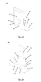
- the picture according to Fig. 1 shows a partial perspective view of a known from the prior art sliding window.
- the illustration shows a corner region of a window frame 2.
- the frame 2 of the sliding window 1 has, in the example shown here, two horizontally extending guide rails 21 and 22, respectively.
- At least one casement 3, for opening and closing the sliding window 1, is displaceably mounted on each of the guide rails 21, 22.
- the wing frame 3 shown here has in particular two horizontal and two vertical frame sections, of which only the right vertical frame section 32 and the lower horizontal frame section 31 are shown.
- the four frame sections of the sash frame 3 enclose an insulating glass pane 33, which is shown in the embodiment shown here as a double glass pane.
- a lower longitudinal groove is provided in the casement 3, which is designed to partially enclose the guide rail 21.
- the longitudinal groove of the casement 3 is formed larger than would be necessary to embrace the guide rail 21 in order to lift the casement 3 during assembly in the guide rail 21 and 22 of the frame 2.
- this creates a free space between the guide rail 21 and the upper end of the longitudinal groove indicated here. From the prior art, it is known to seal this space, for example by insulating foam. However, as already indicated, this has the disadvantage that the introduction is associated with a relatively large effort and only an insufficient sealing effect is achieved.
- a sealing member 40 at the end portion 321 of the longitudinal groove of the sash 3 to install as for example from Fig. 4b is apparent.
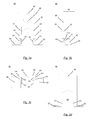
- the exact structure of the sealing element 40 according to the invention is in particular from the Figures 2a to 3d seen.
- the sealing element generally has an anchoring area 60, which is attached to a covering area 50 of the sealing element 40.
- the anchoring area 60 is designed to engage in an interior of the sash 3.
- the cover portion 50 serves to be attached to an outer side of the sash frame and to substantially completely cover the end portion 321 of the longitudinal groove of the sash frame 3.
- the sealing element 40 is in particular formed in one piece, ie the anchoring area 60 is formed integrally with the covering area 50. Accordingly, it is advantageous to produce the sealing element 40 as an injection molded part.
- the anchoring area 60 serves to anchor the sealing element within the sash.
- the anchoring portion 60 is adapted to engage in the interior of the vertical frame portion 32.
- the anchoring area 60 for this purpose has two pressing elements 62, which are formed on an inner wall of the end area (321, FIG. Fig. 1 ) of the longitudinal groove to be attached. Between the two pressing elements 62 extends a passage opening 69 which is dimensioned for the guide rail (21, 22, Fig. 1 ).
- the anchoring area 30, in addition to the pressing elements 62 has sealing elements 63, which are aligned parallel to the pressing elements and extend away from the pressing elements 62.
- the sealing elements 63 are designed to be flexible in order to seal with the guide rail (21, 22, Fig. 1 ) of the frame 2 to be connected.
- the inner surfaces of the flexible sealing members 63 have tapered surfaces, whereby a protruding contact edge 631 is formed.
- the contact edge 631 serves, in particular, for the respective guide rail 21 or 22 of the window frame 2 (FIG. Fig. 1 ) as soon as it is inserted into the through hole 69.
- clamping profiles 61 extend perpendicular to the outside, ie parallel to the covering region 50, on each of the pressing elements 62.
- the clamping profiles 61 together with the covering area 50, form two intermediate spaces 611, which are designed to form a front side wall 323 (FIG. FIGS. 4a, 4b ) of the sash 3 record.
- the cover area 50 facing surface of the clamping profile 61 may in particular be slightly beveled, so that the intermediate region 611 is slightly inclined relative to the vertical.
- the covering region 50 may have on its inner side a wedge-shaped region 64 which has substantially the same bevel relative to the vertical as the clamping profiles 61.
- the wedge-shaped region 64 thereby widens in the direction of the bottom region 65.
- the oblique formation of the intermediate region 611 reinforces the clip action of the sealing element 40 according to the invention.
- a projection 66 which is located on the inside of the cover 50, the sealing element 40 according to the invention, as in connection with the FIGS. 4a and 4b will be explained in more detail, are positively connected to the vertical frame portion 32 of the sash 3.
- an optional through-bore 67 can be provided on the cover region 50, which in addition to the elements of the anchoring region 60 already described can serve to secure the sealing element 40 to the sash frame 3 by means of a fastening screw.
- a substantially horizontally extending bottom portion 65 follows, which is adapted to cover the underside of the sash frame 3, as for example from Fig. 4b is apparent.
- FIGS. 4a and 4b For example, a procedure for installing the sealing element 40 according to the invention can be taken.
- the sealing member 40 according to the invention is applied to the lower portion of the side wall 323 of the vertical frame portion 32, so that the two flexible pressing members 62 are aligned with the end portion 321 of the longitudinal groove.
- a second step which in Fig. 4b is indicated, the sealing member 40 is pushed vertically upwards in the inner region of the vertical frame portion 32 and thus covers the end portion 321 of the longitudinal groove of the sash 3.
- the side wall 323 for receiving the projection 66 has a circular opening 322nd can have.
- the opening 322 can be either already provided during the manufacture of the sash 3 or introduced during assembly of the sealing member 40 with a drill in the side wall 323.
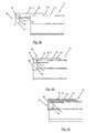
- FIGS. 5a to 5c The insertion of the sealing element 40 into the interior of the vertical frame portion 32 is in the FIGS. 5a to 5c shown in more detail.
- FIGS. 5a and 5b a cross section through the center of the vertical frame portion 32 is shown.
- a representation of the horizontal frame section 31 FIG. Fig. 4a
- Fig. 5a is the in Fig. 4a shown installation state of the sealing element 40 in section.
- FIG. 5b This condition is in the Fig. 5b shown. It should first be noted that in Fig. 5b only the vertical frame portion 32 is shown in section, whereas the sealing member 40 is present in a non-cut side view. In the state according to Fig. 5b the sealing element 40 is pushed so far into the interior of the vertical frame portion 32 that the substantially horizontally extending bottom portions 65 abut the underside of the sash. At the same time, the projection 66 of the sealing element 40 snaps into the opening 322, whereby a positive connection of the sealing element 40 with the vertical frame section 32 of the sash frame 3 is achieved. The determination of the projection 66 in the opening 322 is made by pinching the side wall 323 within the gap 611, as with respect to the Fig. 5c will be explained in more detail.
- Fig. 5c is a laterally offset cross-section, which is located adjacent to the opening of the end portion 321 shown.
- the side wall 323 of the vertical frame portion 32 is clamped in the space 611 of the sealing member 40.
- the front side wall 323 of the vertical frame section 32 is thereby clamped between the cover region 50 and the clamping profile 61 running parallel thereto.
- the intermediate space 611 is formed in particular obliquely to the cover area 50, arises during insertion of the Side wall 323 in the intermediate region 611 a torque which braces the projection 66 in the direction of the opening 322.
- a pressing action of the cover portion 50 to the side wall 323 of the vertical frame portion 32 is effected.
- Fig. 6 Once again shown how the sealing element 40 of the invention can be attached to the sash 3 of a sliding window.
- the sealing element 40 is placed in the open state of the sliding window on the respective guide rail 21 and displaced in the direction of the end portion 321 of the longitudinal groove until the position shown in the illustration above right, which the state of Fig. 5a corresponds, is achieved.
- a pointed object such as a screwdriver 70
Landscapes
- Engineering & Computer Science (AREA)
- Civil Engineering (AREA)
- Structural Engineering (AREA)
- Specific Sealing Or Ventilating Devices For Doors And Windows (AREA)
Priority Applications (1)
| Application Number | Priority Date | Filing Date | Title |
|---|---|---|---|
| EP15154963.1A EP2907960B1 (fr) | 2014-02-13 | 2015-02-13 | Élément d'étanchéité pour fenêtres coulissantes et portes coulissantes |
Applications Claiming Priority (2)
| Application Number | Priority Date | Filing Date | Title |
|---|---|---|---|
| EP14155020 | 2014-02-13 | ||
| EP15154963.1A EP2907960B1 (fr) | 2014-02-13 | 2015-02-13 | Élément d'étanchéité pour fenêtres coulissantes et portes coulissantes |
Publications (2)
| Publication Number | Publication Date |
|---|---|
| EP2907960A1 true EP2907960A1 (fr) | 2015-08-19 |
| EP2907960B1 EP2907960B1 (fr) | 2018-04-04 |
Family
ID=50097609
Family Applications (1)
| Application Number | Title | Priority Date | Filing Date |
|---|---|---|---|
| EP15154963.1A Active EP2907960B1 (fr) | 2014-02-13 | 2015-02-13 | Élément d'étanchéité pour fenêtres coulissantes et portes coulissantes |
Country Status (1)
| Country | Link |
|---|---|
| EP (1) | EP2907960B1 (fr) |
Citations (4)
| Publication number | Priority date | Publication date | Assignee | Title |
|---|---|---|---|---|
| FR2839740A3 (fr) * | 2002-05-16 | 2003-11-21 | Tecseal | Bourrelet perfectionne |
| US20040040214A1 (en) * | 2002-08-28 | 2004-03-04 | Bitner Garold B. | Door-mounted bug barrier apparatus |
| US20070264466A1 (en) * | 2006-05-15 | 2007-11-15 | Demello Alan J | Weatherstrip with releasable protective covering |
| DE202008001251U1 (de) * | 2008-01-28 | 2008-04-17 | Gretsch-Unitas GmbH Baubeschläge | Auf einer Laufschiene verfahrbare Hebeschiebetür |
-
2015
- 2015-02-13 EP EP15154963.1A patent/EP2907960B1/fr active Active
Patent Citations (4)
| Publication number | Priority date | Publication date | Assignee | Title |
|---|---|---|---|---|
| FR2839740A3 (fr) * | 2002-05-16 | 2003-11-21 | Tecseal | Bourrelet perfectionne |
| US20040040214A1 (en) * | 2002-08-28 | 2004-03-04 | Bitner Garold B. | Door-mounted bug barrier apparatus |
| US20070264466A1 (en) * | 2006-05-15 | 2007-11-15 | Demello Alan J | Weatherstrip with releasable protective covering |
| DE202008001251U1 (de) * | 2008-01-28 | 2008-04-17 | Gretsch-Unitas GmbH Baubeschläge | Auf einer Laufschiene verfahrbare Hebeschiebetür |
Also Published As
| Publication number | Publication date |
|---|---|
| EP2907960B1 (fr) | 2018-04-04 |
Similar Documents
| Publication | Publication Date | Title |
|---|---|---|
| DE4433145A1 (de) | Magnetische Türdichtung | |
| EP2088337A2 (fr) | Profilé et système de profilés | |
| DD139749A5 (de) | Eck-oder t-verbindung zweier profile | |
| DE202020106414U1 (de) | Tor | |
| DE102018132206B3 (de) | Scharniersystem, Fahrzeugaufbau, Fahrzeug und Verfahren zur Montage einer Türe | |
| EP2060728B1 (fr) | Barre de retenue d'une vitre, construction de cadre et procédé destiné au montage d'une barre de retenue d'une vitre | |
| EP2708693B1 (fr) | Cadre de battant ouvrant-coulissant | |
| DE19758464C2 (de) | Isolierelement aus wenigstens zwei Glas- oder Kunststoffscheiben und mit Profilschienen oder -teilen zur Montage in einem Rahmen | |
| EP2907960B1 (fr) | Élément d'étanchéité pour fenêtres coulissantes et portes coulissantes | |
| DE19740603C2 (de) | Stulpschienenbefestigung | |
| DE202012004988U1 (de) | Bauelement | |
| EP2759666B1 (fr) | Ferrure avec élément de profilé | |
| DE19808847C2 (de) | Tür- oder Fensterbeschlag | |
| AT512327A1 (de) | Hebe/schiebetür | |
| EP2341209B1 (fr) | Agencement de profilé | |
| DE102008006800A1 (de) | Führungsvorrichtung für einen Schiebeflügel | |
| EP2339095B1 (fr) | Porte, notamment porte en plastique, dotée d'une sécurité de palastre | |
| EP1688577B1 (fr) | Languette de raccord pour fixer des cadres de fenêtre ou porte à un cadre de base ou à un mur | |
| DE102014107166A1 (de) | Anordnung aus einem Verbundteil und Rahmenteilen eines Fahrzeugtürfensters | |
| DE19734647B4 (de) | Beschlagteil an einem Flügel oder einem festen Rahmen eines Fensters, einer Tür od. dgl. | |
| EP2333213A2 (fr) | Guide pour ouvrant coulissant | |
| DE202007019257U1 (de) | Glashalteleiste, Rahmenkonstruktion | |
| DE102011008765A1 (de) | Profilanordnung, Rahmen und Rahmenanordnung | |
| EP1835120A1 (fr) | Fenêtre de toit avec feuillure ajustable | |
| DE19847316A1 (de) | Profilteil für Türschwellen und Türschwelle mit einer abfallend verlaufenden Oberseite |
Legal Events
| Date | Code | Title | Description |
|---|---|---|---|
| PUAI | Public reference made under article 153(3) epc to a published international application that has entered the european phase |
Free format text: ORIGINAL CODE: 0009012 |
|
| AK | Designated contracting states |
Kind code of ref document: A1 Designated state(s): AL AT BE BG CH CY CZ DE DK EE ES FI FR GB GR HR HU IE IS IT LI LT LU LV MC MK MT NL NO PL PT RO RS SE SI SK SM TR |
|
| AX | Request for extension of the european patent |
Extension state: BA ME |
|
| 17P | Request for examination filed |
Effective date: 20160218 |
|
| RBV | Designated contracting states (corrected) |
Designated state(s): AL AT BE BG CH CY CZ DE DK EE ES FI FR GB GR HR HU IE IS IT LI LT LU LV MC MK MT NL NO PL PT RO RS SE SI SK SM TR |
|
| RAP1 | Party data changed (applicant data changed or rights of an application transferred) |
Owner name: KAWNEER ALUMINIUM DEUTSCHLAND INC. |
|
| GRAP | Despatch of communication of intention to grant a patent |
Free format text: ORIGINAL CODE: EPIDOSNIGR1 |
|
| STAA | Information on the status of an ep patent application or granted ep patent |
Free format text: STATUS: GRANT OF PATENT IS INTENDED |
|
| RIC1 | Information provided on ipc code assigned before grant |
Ipc: E06B 7/16 20060101AFI20170731BHEP |
|
| INTG | Intention to grant announced |
Effective date: 20170905 |
|
| GRAS | Grant fee paid |
Free format text: ORIGINAL CODE: EPIDOSNIGR3 |
|
| GRAA | (expected) grant |
Free format text: ORIGINAL CODE: 0009210 |
|
| STAA | Information on the status of an ep patent application or granted ep patent |
Free format text: STATUS: THE PATENT HAS BEEN GRANTED |
|
| AK | Designated contracting states |
Kind code of ref document: B1 Designated state(s): AL AT BE BG CH CY CZ DE DK EE ES FI FR GB GR HR HU IE IS IT LI LT LU LV MC MK MT NL NO PL PT RO RS SE SI SK SM TR |
|
| REG | Reference to a national code |
Ref country code: GB Ref legal event code: FG4D Free format text: NOT ENGLISH |
|
| REG | Reference to a national code |
Ref country code: CH Ref legal event code: EP |
|
| REG | Reference to a national code |
Ref country code: AT Ref legal event code: REF Ref document number: 985786 Country of ref document: AT Kind code of ref document: T Effective date: 20180415 |
|
| REG | Reference to a national code |
Ref country code: IE Ref legal event code: FG4D Free format text: LANGUAGE OF EP DOCUMENT: GERMAN |
|
| REG | Reference to a national code |
Ref country code: DE Ref legal event code: R096 Ref document number: 502015003675 Country of ref document: DE |
|
| REG | Reference to a national code |
Ref country code: NL Ref legal event code: MP Effective date: 20180404 |
|
| REG | Reference to a national code |
Ref country code: LT Ref legal event code: MG4D |
|
| PG25 | Lapsed in a contracting state [announced via postgrant information from national office to epo] |
Ref country code: NL Free format text: LAPSE BECAUSE OF FAILURE TO SUBMIT A TRANSLATION OF THE DESCRIPTION OR TO PAY THE FEE WITHIN THE PRESCRIBED TIME-LIMIT Effective date: 20180404 |
|
| PG25 | Lapsed in a contracting state [announced via postgrant information from national office to epo] |
Ref country code: NO Free format text: LAPSE BECAUSE OF FAILURE TO SUBMIT A TRANSLATION OF THE DESCRIPTION OR TO PAY THE FEE WITHIN THE PRESCRIBED TIME-LIMIT Effective date: 20180704 Ref country code: FI Free format text: LAPSE BECAUSE OF FAILURE TO SUBMIT A TRANSLATION OF THE DESCRIPTION OR TO PAY THE FEE WITHIN THE PRESCRIBED TIME-LIMIT Effective date: 20180404 Ref country code: BG Free format text: LAPSE BECAUSE OF FAILURE TO SUBMIT A TRANSLATION OF THE DESCRIPTION OR TO PAY THE FEE WITHIN THE PRESCRIBED TIME-LIMIT Effective date: 20180704 Ref country code: ES Free format text: LAPSE BECAUSE OF FAILURE TO SUBMIT A TRANSLATION OF THE DESCRIPTION OR TO PAY THE FEE WITHIN THE PRESCRIBED TIME-LIMIT Effective date: 20180404 Ref country code: SE Free format text: LAPSE BECAUSE OF FAILURE TO SUBMIT A TRANSLATION OF THE DESCRIPTION OR TO PAY THE FEE WITHIN THE PRESCRIBED TIME-LIMIT Effective date: 20180404 Ref country code: AL Free format text: LAPSE BECAUSE OF FAILURE TO SUBMIT A TRANSLATION OF THE DESCRIPTION OR TO PAY THE FEE WITHIN THE PRESCRIBED TIME-LIMIT Effective date: 20180404 Ref country code: PL Free format text: LAPSE BECAUSE OF FAILURE TO SUBMIT A TRANSLATION OF THE DESCRIPTION OR TO PAY THE FEE WITHIN THE PRESCRIBED TIME-LIMIT Effective date: 20180404 Ref country code: LT Free format text: LAPSE BECAUSE OF FAILURE TO SUBMIT A TRANSLATION OF THE DESCRIPTION OR TO PAY THE FEE WITHIN THE PRESCRIBED TIME-LIMIT Effective date: 20180404 |
|
| PG25 | Lapsed in a contracting state [announced via postgrant information from national office to epo] |
Ref country code: LV Free format text: LAPSE BECAUSE OF FAILURE TO SUBMIT A TRANSLATION OF THE DESCRIPTION OR TO PAY THE FEE WITHIN THE PRESCRIBED TIME-LIMIT Effective date: 20180404 Ref country code: GR Free format text: LAPSE BECAUSE OF FAILURE TO SUBMIT A TRANSLATION OF THE DESCRIPTION OR TO PAY THE FEE WITHIN THE PRESCRIBED TIME-LIMIT Effective date: 20180705 Ref country code: HR Free format text: LAPSE BECAUSE OF FAILURE TO SUBMIT A TRANSLATION OF THE DESCRIPTION OR TO PAY THE FEE WITHIN THE PRESCRIBED TIME-LIMIT Effective date: 20180404 Ref country code: RS Free format text: LAPSE BECAUSE OF FAILURE TO SUBMIT A TRANSLATION OF THE DESCRIPTION OR TO PAY THE FEE WITHIN THE PRESCRIBED TIME-LIMIT Effective date: 20180404 |
|
| PG25 | Lapsed in a contracting state [announced via postgrant information from national office to epo] |
Ref country code: PT Free format text: LAPSE BECAUSE OF FAILURE TO SUBMIT A TRANSLATION OF THE DESCRIPTION OR TO PAY THE FEE WITHIN THE PRESCRIBED TIME-LIMIT Effective date: 20180806 |
|
| REG | Reference to a national code |
Ref country code: DE Ref legal event code: R097 Ref document number: 502015003675 Country of ref document: DE |
|
| PG25 | Lapsed in a contracting state [announced via postgrant information from national office to epo] |
Ref country code: DK Free format text: LAPSE BECAUSE OF FAILURE TO SUBMIT A TRANSLATION OF THE DESCRIPTION OR TO PAY THE FEE WITHIN THE PRESCRIBED TIME-LIMIT Effective date: 20180404 Ref country code: EE Free format text: LAPSE BECAUSE OF FAILURE TO SUBMIT A TRANSLATION OF THE DESCRIPTION OR TO PAY THE FEE WITHIN THE PRESCRIBED TIME-LIMIT Effective date: 20180404 Ref country code: RO Free format text: LAPSE BECAUSE OF FAILURE TO SUBMIT A TRANSLATION OF THE DESCRIPTION OR TO PAY THE FEE WITHIN THE PRESCRIBED TIME-LIMIT Effective date: 20180404 Ref country code: CZ Free format text: LAPSE BECAUSE OF FAILURE TO SUBMIT A TRANSLATION OF THE DESCRIPTION OR TO PAY THE FEE WITHIN THE PRESCRIBED TIME-LIMIT Effective date: 20180404 Ref country code: SK Free format text: LAPSE BECAUSE OF FAILURE TO SUBMIT A TRANSLATION OF THE DESCRIPTION OR TO PAY THE FEE WITHIN THE PRESCRIBED TIME-LIMIT Effective date: 20180404 |
|
| PLBE | No opposition filed within time limit |
Free format text: ORIGINAL CODE: 0009261 |
|
| STAA | Information on the status of an ep patent application or granted ep patent |
Free format text: STATUS: NO OPPOSITION FILED WITHIN TIME LIMIT |
|
| PG25 | Lapsed in a contracting state [announced via postgrant information from national office to epo] |
Ref country code: IT Free format text: LAPSE BECAUSE OF FAILURE TO SUBMIT A TRANSLATION OF THE DESCRIPTION OR TO PAY THE FEE WITHIN THE PRESCRIBED TIME-LIMIT Effective date: 20180404 Ref country code: SM Free format text: LAPSE BECAUSE OF FAILURE TO SUBMIT A TRANSLATION OF THE DESCRIPTION OR TO PAY THE FEE WITHIN THE PRESCRIBED TIME-LIMIT Effective date: 20180404 |
|
| 26N | No opposition filed |
Effective date: 20190107 |
|
| PG25 | Lapsed in a contracting state [announced via postgrant information from national office to epo] |
Ref country code: SI Free format text: LAPSE BECAUSE OF FAILURE TO SUBMIT A TRANSLATION OF THE DESCRIPTION OR TO PAY THE FEE WITHIN THE PRESCRIBED TIME-LIMIT Effective date: 20180404 |
|
| REG | Reference to a national code |
Ref country code: DE Ref legal event code: R082 Ref document number: 502015003675 Country of ref document: DE Representative=s name: MEISSNER BOLTE PATENTANWAELTE RECHTSANWAELTE P, DE |
|
| REG | Reference to a national code |
Ref country code: CH Ref legal event code: PL |
|
| PG25 | Lapsed in a contracting state [announced via postgrant information from national office to epo] |
Ref country code: MC Free format text: LAPSE BECAUSE OF FAILURE TO SUBMIT A TRANSLATION OF THE DESCRIPTION OR TO PAY THE FEE WITHIN THE PRESCRIBED TIME-LIMIT Effective date: 20180404 Ref country code: LU Free format text: LAPSE BECAUSE OF NON-PAYMENT OF DUE FEES Effective date: 20190213 |
|
| REG | Reference to a national code |
Ref country code: BE Ref legal event code: MM Effective date: 20190228 |
|
| REG | Reference to a national code |
Ref country code: IE Ref legal event code: MM4A |
|
| PG25 | Lapsed in a contracting state [announced via postgrant information from national office to epo] |
Ref country code: LI Free format text: LAPSE BECAUSE OF NON-PAYMENT OF DUE FEES Effective date: 20190228 Ref country code: CH Free format text: LAPSE BECAUSE OF NON-PAYMENT OF DUE FEES Effective date: 20190228 |
|
| PG25 | Lapsed in a contracting state [announced via postgrant information from national office to epo] |
Ref country code: IE Free format text: LAPSE BECAUSE OF NON-PAYMENT OF DUE FEES Effective date: 20190213 |
|
| PG25 | Lapsed in a contracting state [announced via postgrant information from national office to epo] |
Ref country code: BE Free format text: LAPSE BECAUSE OF NON-PAYMENT OF DUE FEES Effective date: 20190228 |
|
| PG25 | Lapsed in a contracting state [announced via postgrant information from national office to epo] |
Ref country code: TR Free format text: LAPSE BECAUSE OF FAILURE TO SUBMIT A TRANSLATION OF THE DESCRIPTION OR TO PAY THE FEE WITHIN THE PRESCRIBED TIME-LIMIT Effective date: 20180404 |
|
| PG25 | Lapsed in a contracting state [announced via postgrant information from national office to epo] |
Ref country code: MT Free format text: LAPSE BECAUSE OF FAILURE TO SUBMIT A TRANSLATION OF THE DESCRIPTION OR TO PAY THE FEE WITHIN THE PRESCRIBED TIME-LIMIT Effective date: 20180404 |
|
| REG | Reference to a national code |
Ref country code: AT Ref legal event code: MM01 Ref document number: 985786 Country of ref document: AT Kind code of ref document: T Effective date: 20200213 |
|
| PG25 | Lapsed in a contracting state [announced via postgrant information from national office to epo] |
Ref country code: AT Free format text: LAPSE BECAUSE OF NON-PAYMENT OF DUE FEES Effective date: 20200213 Ref country code: CY Free format text: LAPSE BECAUSE OF FAILURE TO SUBMIT A TRANSLATION OF THE DESCRIPTION OR TO PAY THE FEE WITHIN THE PRESCRIBED TIME-LIMIT Effective date: 20180404 |
|
| PG25 | Lapsed in a contracting state [announced via postgrant information from national office to epo] |
Ref country code: IS Free format text: LAPSE BECAUSE OF FAILURE TO SUBMIT A TRANSLATION OF THE DESCRIPTION OR TO PAY THE FEE WITHIN THE PRESCRIBED TIME-LIMIT Effective date: 20180804 |
|
| PG25 | Lapsed in a contracting state [announced via postgrant information from national office to epo] |
Ref country code: HU Free format text: LAPSE BECAUSE OF FAILURE TO SUBMIT A TRANSLATION OF THE DESCRIPTION OR TO PAY THE FEE WITHIN THE PRESCRIBED TIME-LIMIT; INVALID AB INITIO Effective date: 20150213 |
|
| PG25 | Lapsed in a contracting state [announced via postgrant information from national office to epo] |
Ref country code: MK Free format text: LAPSE BECAUSE OF FAILURE TO SUBMIT A TRANSLATION OF THE DESCRIPTION OR TO PAY THE FEE WITHIN THE PRESCRIBED TIME-LIMIT Effective date: 20180404 |
|
| PGFP | Annual fee paid to national office [announced via postgrant information from national office to epo] |
Ref country code: FR Payment date: 20230119 Year of fee payment: 9 |
|
| P01 | Opt-out of the competence of the unified patent court (upc) registered |
Effective date: 20230517 |
|
| PGFP | Annual fee paid to national office [announced via postgrant information from national office to epo] |
Ref country code: DE Payment date: 20240123 Year of fee payment: 10 Ref country code: GB Payment date: 20240123 Year of fee payment: 10 |