EP2907960A1 - Sealing element for sliding window and sliding doors - Google Patents
Sealing element for sliding window and sliding doors Download PDFInfo
- Publication number
- EP2907960A1 EP2907960A1 EP15154963.1A EP15154963A EP2907960A1 EP 2907960 A1 EP2907960 A1 EP 2907960A1 EP 15154963 A EP15154963 A EP 15154963A EP 2907960 A1 EP2907960 A1 EP 2907960A1
- Authority
- EP
- European Patent Office
- Prior art keywords
- sealing element
- sash
- sealing
- frame
- longitudinal groove
- Prior art date
- Legal status (The legal status is an assumption and is not a legal conclusion. Google has not performed a legal analysis and makes no representation as to the accuracy of the status listed.)
- Granted
Links
Images


Classifications
-
- E—FIXED CONSTRUCTIONS
- E06—DOORS, WINDOWS, SHUTTERS, OR ROLLER BLINDS IN GENERAL; LADDERS
- E06B—FIXED OR MOVABLE CLOSURES FOR OPENINGS IN BUILDINGS, VEHICLES, FENCES OR LIKE ENCLOSURES IN GENERAL, e.g. DOORS, WINDOWS, BLINDS, GATES
- E06B7/00—Special arrangements or measures in connection with doors or windows
- E06B7/16—Sealing arrangements on wings or parts co-operating with the wings
Definitions
- the present invention relates to a sealing element for sealing a casement with respect to a guide rail of a window frame.
- the invention relates to a sealing element for sealing sliding windows and sliding doors.
- the present invention relates to a sliding window or a sliding door with such a sealing element.
- sliding windows and sliding doors consist of a sash which is slidably mounted on a guide rail of a window frame.
- the wing frame on its top and bottom longitudinal grooves, which are adapted to receive the guide rail of the frame and enclose.
- the present invention has the object to provide a sealing element for sliding windows and sliding doors, which can be quickly and easily connected to the longitudinal groove of a sash and at the same time achieves a particularly high sealing effect.
- the novel sealing element even under heavy load, be firmly connected to the sash.
- the sealing element according to the invention for sealing a casement with respect to a guide rail of a window frame on an anchoring area and a cover, which are integrally formed with each other.
- the anchoring area is designed, in particular, to engage in an interior of the casement and to fasten the sealing element to the casement.
- the covering area is designed to cover the Lägnsnut the sash substantially completely. For this purpose, the cover is attached to an outside of the sash.
- the sealing element according to the invention is obvious: So it is possible by the integral formation of the sealing element, time in the Save installation on the casement, since only one step is necessary for fixing the covering area and the anchoring area. Of course, this simultaneously simplifies the entire assembly process considerably.
- the sealing element according to the invention can be frictionally connected to the casement, whereby an independent release of the sealing element from the casement is effectively prevented.
- the sealing element according to the invention is in the installed state in close contact with a side wall of the sash, whereby a particularly high sealing effect is achieved.
- the anchoring area provision is made for the anchoring area to have flexible pressing elements which can be attached to an inner wall of the longitudinal groove such that a frictional connection is created between the longitudinal groove and the sealing element.
- the flexible pressing elements may in particular have a substantially vertical orientation so that they serve as guide elements when the sealing element is pushed onto the casement frame. Due to the flexible design of the pressing is also achieved that the sealing element according to the invention, even if not exactly met tolerances of the longitudinal groove, quickly and easily fastened to the casement.
- the anchoring area further comprises clamping profiles which are aligned perpendicular to the flexible pressing elements and parallel to the covering area.
- the clamping profiles are designed to clamp a first wall portion of the sash between the clamping profiles and the cover.
- an intermediate space is created by the clamping profiles between the covering area and the clamping profiles, which serves to introduce a first wall area of the casement.
- the clamping profiles are spaced further from the cover profile in such a way that the intermediate space created thereby corresponds exactly to the width of said wall region.
- this is the fastening effect the sealing element according to the invention on the casement even further improved.
- the anchoring region has flexible sealing elements, which are aligned parallel to the pressing elements of the anchoring region and adapted to be sealingly connected to the guide rail of the window frame. Due to the flexible sealing elements, the sealing element according to the invention when pushed onto the casement is at the same time connected to the guide rail of the window frame. The flexible design of the sealing elements is further ensured that they are in close contact with the guide rail and thus effectively prevent any air exchange between the guide rail and the interior of the sash.
- the covering region of the sealing element according to the invention has a projection which is arranged on a side of the covering region facing the anchoring region.
- the projection is in particular adapted to engage in a designated opening of the sash.
- the projection may be formed, for example, circular or semicircular, so that it can engage in an additional bore on the side wall of the sash.
- the anchoring region of the sealing element additionally has a substantially horizontally extending bottom region, which is designed to cover an underside of the casement.
- the substantially horizontally extending bottom area once again improves the sealing effect between the casement and the guide rail of the window frame.
- the bottom portion also forms a stop, to which the sealing element can be pushed onto the casement.
- the anchoring region of the sealing element in addition to attachment to the casement, be adapted to fasten a foam element above the guide rail, in the interior of the window sash. It is conceivable, for example, that the above-mentioned pressing elements are adapted to fix an existing of a foamed material insulating layer in the interior of the sash. Of course, this further enhances the sealing effect of the sealing element according to the invention.
- the sealing element is preferably formed from a plastic material. Accordingly, it is ensured that arise through the sealing element no thermal bridges on the sash. Furthermore, it is preferable to form the sealing element as an injection-molded part, whereby the production can be simplified and costs can be saved.
- the present invention also relates to a sliding window or a sliding door which has at least one sealing element according to the invention.
- the sliding window according to the invention comprises a frame and at least one wing frame, wherein the wing frame is slidably mounted on a guide rail of the frame via a longitudinal groove.
- the casement has at least one sealing element according to the invention, which is releasably attached to one end of the longitudinal groove.
- the sliding window according to the invention or the sliding door according to the invention has a particularly high sealing effect, since the longitudinal groove of the sash is reliably sealed.
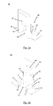
- the picture according to Fig. 1 shows a partial perspective view of a known from the prior art sliding window.
- the illustration shows a corner region of a window frame 2.
- the frame 2 of the sliding window 1 has, in the example shown here, two horizontally extending guide rails 21 and 22, respectively.
- At least one casement 3, for opening and closing the sliding window 1, is displaceably mounted on each of the guide rails 21, 22.
- the wing frame 3 shown here has in particular two horizontal and two vertical frame sections, of which only the right vertical frame section 32 and the lower horizontal frame section 31 are shown.
- the four frame sections of the sash frame 3 enclose an insulating glass pane 33, which is shown in the embodiment shown here as a double glass pane.
- a lower longitudinal groove is provided in the casement 3, which is designed to partially enclose the guide rail 21.
- the longitudinal groove of the casement 3 is formed larger than would be necessary to embrace the guide rail 21 in order to lift the casement 3 during assembly in the guide rail 21 and 22 of the frame 2.
- this creates a free space between the guide rail 21 and the upper end of the longitudinal groove indicated here. From the prior art, it is known to seal this space, for example by insulating foam. However, as already indicated, this has the disadvantage that the introduction is associated with a relatively large effort and only an insufficient sealing effect is achieved.
- a sealing member 40 at the end portion 321 of the longitudinal groove of the sash 3 to install as for example from Fig. 4b is apparent.
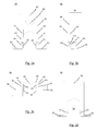
- the exact structure of the sealing element 40 according to the invention is in particular from the Figures 2a to 3d seen.
- the sealing element generally has an anchoring area 60, which is attached to a covering area 50 of the sealing element 40.
- the anchoring area 60 is designed to engage in an interior of the sash 3.
- the cover portion 50 serves to be attached to an outer side of the sash frame and to substantially completely cover the end portion 321 of the longitudinal groove of the sash frame 3.
- the sealing element 40 is in particular formed in one piece, ie the anchoring area 60 is formed integrally with the covering area 50. Accordingly, it is advantageous to produce the sealing element 40 as an injection molded part.
- the anchoring area 60 serves to anchor the sealing element within the sash.
- the anchoring portion 60 is adapted to engage in the interior of the vertical frame portion 32.
- the anchoring area 60 for this purpose has two pressing elements 62, which are formed on an inner wall of the end area (321, FIG. Fig. 1 ) of the longitudinal groove to be attached. Between the two pressing elements 62 extends a passage opening 69 which is dimensioned for the guide rail (21, 22, Fig. 1 ).
- the anchoring area 30, in addition to the pressing elements 62 has sealing elements 63, which are aligned parallel to the pressing elements and extend away from the pressing elements 62.
- the sealing elements 63 are designed to be flexible in order to seal with the guide rail (21, 22, Fig. 1 ) of the frame 2 to be connected.
- the inner surfaces of the flexible sealing members 63 have tapered surfaces, whereby a protruding contact edge 631 is formed.
- the contact edge 631 serves, in particular, for the respective guide rail 21 or 22 of the window frame 2 (FIG. Fig. 1 ) as soon as it is inserted into the through hole 69.
- clamping profiles 61 extend perpendicular to the outside, ie parallel to the covering region 50, on each of the pressing elements 62.
- the clamping profiles 61 together with the covering area 50, form two intermediate spaces 611, which are designed to form a front side wall 323 (FIG. FIGS. 4a, 4b ) of the sash 3 record.
- the cover area 50 facing surface of the clamping profile 61 may in particular be slightly beveled, so that the intermediate region 611 is slightly inclined relative to the vertical.
- the covering region 50 may have on its inner side a wedge-shaped region 64 which has substantially the same bevel relative to the vertical as the clamping profiles 61.
- the wedge-shaped region 64 thereby widens in the direction of the bottom region 65.
- the oblique formation of the intermediate region 611 reinforces the clip action of the sealing element 40 according to the invention.
- a projection 66 which is located on the inside of the cover 50, the sealing element 40 according to the invention, as in connection with the FIGS. 4a and 4b will be explained in more detail, are positively connected to the vertical frame portion 32 of the sash 3.
- an optional through-bore 67 can be provided on the cover region 50, which in addition to the elements of the anchoring region 60 already described can serve to secure the sealing element 40 to the sash frame 3 by means of a fastening screw.
- a substantially horizontally extending bottom portion 65 follows, which is adapted to cover the underside of the sash frame 3, as for example from Fig. 4b is apparent.
- FIGS. 4a and 4b For example, a procedure for installing the sealing element 40 according to the invention can be taken.
- the sealing member 40 according to the invention is applied to the lower portion of the side wall 323 of the vertical frame portion 32, so that the two flexible pressing members 62 are aligned with the end portion 321 of the longitudinal groove.
- a second step which in Fig. 4b is indicated, the sealing member 40 is pushed vertically upwards in the inner region of the vertical frame portion 32 and thus covers the end portion 321 of the longitudinal groove of the sash 3.
- the side wall 323 for receiving the projection 66 has a circular opening 322nd can have.
- the opening 322 can be either already provided during the manufacture of the sash 3 or introduced during assembly of the sealing member 40 with a drill in the side wall 323.
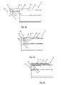
- FIGS. 5a to 5c The insertion of the sealing element 40 into the interior of the vertical frame portion 32 is in the FIGS. 5a to 5c shown in more detail.
- FIGS. 5a and 5b a cross section through the center of the vertical frame portion 32 is shown.
- a representation of the horizontal frame section 31 FIG. Fig. 4a
- Fig. 5a is the in Fig. 4a shown installation state of the sealing element 40 in section.
- FIG. 5b This condition is in the Fig. 5b shown. It should first be noted that in Fig. 5b only the vertical frame portion 32 is shown in section, whereas the sealing member 40 is present in a non-cut side view. In the state according to Fig. 5b the sealing element 40 is pushed so far into the interior of the vertical frame portion 32 that the substantially horizontally extending bottom portions 65 abut the underside of the sash. At the same time, the projection 66 of the sealing element 40 snaps into the opening 322, whereby a positive connection of the sealing element 40 with the vertical frame section 32 of the sash frame 3 is achieved. The determination of the projection 66 in the opening 322 is made by pinching the side wall 323 within the gap 611, as with respect to the Fig. 5c will be explained in more detail.
- Fig. 5c is a laterally offset cross-section, which is located adjacent to the opening of the end portion 321 shown.
- the side wall 323 of the vertical frame portion 32 is clamped in the space 611 of the sealing member 40.
- the front side wall 323 of the vertical frame section 32 is thereby clamped between the cover region 50 and the clamping profile 61 running parallel thereto.
- the intermediate space 611 is formed in particular obliquely to the cover area 50, arises during insertion of the Side wall 323 in the intermediate region 611 a torque which braces the projection 66 in the direction of the opening 322.
- a pressing action of the cover portion 50 to the side wall 323 of the vertical frame portion 32 is effected.
- Fig. 6 Once again shown how the sealing element 40 of the invention can be attached to the sash 3 of a sliding window.
- the sealing element 40 is placed in the open state of the sliding window on the respective guide rail 21 and displaced in the direction of the end portion 321 of the longitudinal groove until the position shown in the illustration above right, which the state of Fig. 5a corresponds, is achieved.
- a pointed object such as a screwdriver 70
Abstract
Die vorliegende Erfindung betrifft ein Dichtungselement (40) zum Abdichten eines Flügelrahmens (3) gegenüber einer Führungsschiene (21, 22) eines Blendrahmens (2). Das Dichtungselement (40) weist einen Verankerungsbereich (60), welcher dazu ausgebildet ist in einen Innenraum des Flügelrahmens (3) einzugreifen und das Dichtungselement (40) an dem Flügelrahmen (3) zu befestigen, und einen Abdeckbereich (50), welcher dazu ausgebildet ist an einer Außenseite des Flügelrahmens (3) angebracht zu werden und eine Längsnut des Flügelrahmens (3) im Wesentlichen vollständig zu überdecken, auf. Um die Montage des erfindungsgemäßen Dichtungselements (40) zu vereinfachen und die Dichteigenschaften zu erhöhen ist es vorgesehen, dass das Dichtungselement (40) einstückig ausgebildet ist.The present invention relates to a sealing element (40) for sealing a casement frame (3) relative to a guide rail (21, 22) of a window frame (2). The sealing member (40) has an anchoring portion (60) adapted to engage an inner space of the sash (3) and attach the sealing member (40) to the sash (3), and a cover portion (50) formed therefor is to be attached to an outer side of the sash (3) and to substantially completely cover a longitudinal groove of the sash (3). In order to simplify the assembly of the sealing element (40) according to the invention and to increase the sealing properties, it is provided that the sealing element (40) is formed in one piece.
Description
Die vorliegende Erfindung betrifft ein Dichtungselement zum Abdichten eines Flügelrahmens gegenüber einer Führungsschiene eines Blendrahmens. Insbesondere betrifft die Erfindung ein Dichtungselement zum Abdichten von Schiebefenstern und Schiebetüren. Darüber hinaus bezieht sich die vorliegende Erfindung auf ein Schiebefenster oder eine Schiebetür mit einem derartigen Dichtungselement.The present invention relates to a sealing element for sealing a casement with respect to a guide rail of a window frame. In particular, the invention relates to a sealing element for sealing sliding windows and sliding doors. Moreover, the present invention relates to a sliding window or a sliding door with such a sealing element.
Insbesondere Schiebefenster und Schiebetüren bestehen aus einem Flügelrahmen, welcher auf einer Führungsschiene eines Blendrahmens verschiebbar gelagert ist. Hierzu weist der Flügelrahmen an seiner Ober- und Unterseite Längsnuten auf, welche dazu ausgebildet sind die Führungsschiene des Blendrahmens aufzunehmen und zu umschließen. Um die Flügelrahmen auch nach dem Zusammenbau des Blendrahmens auf die Führungsschienen aufstecken zu können, ist es aus dem Stand der Technik bekannt, wenigstens eine der Längsnuten des Flügelrahmens tiefer auszugestalten, als es für die Aufnahme der Führungsschiene nötig wäre. Demzufolge entsteht ein Freiraum zwischen der Führungsschiene und dem Profil des Flügelrahmens, welcher zur Ausbildung ungewollter Wärmebrücken zwischen der Außenseite und der Innenseite des Fensters bzw. der Tür führt.In particular sliding windows and sliding doors consist of a sash which is slidably mounted on a guide rail of a window frame. For this purpose, the wing frame on its top and bottom longitudinal grooves, which are adapted to receive the guide rail of the frame and enclose. In order to attach the casement even after the assembly of the frame on the guide rails, it is known from the prior art to design at least one of the longitudinal grooves of the casement deeper than would be necessary for receiving the guide rail. Consequently, there is a clearance between the guide rail and the profile of the sash, which leads to the formation of unwanted heat bridges between the outside and the inside of the window or the door.
Aus den oben genannten Gründen ist es aus dem Stand der Technik bekannt, zumindest den Endbereich der Längsnuten des Flügelrahmens gegenüber der Führungsschiene des Blendrahmens, nach dem Einsetzen des Flügelrahmens in den Blendrahmen, abzudichten. Hierzu ist es beispielsweise bekannt, schaumartiges Dämmaterial zumindest im Randbereich der Längsnut vorzusehen, welcher den Freiraum zwischen dem Flügelrahmen und der Führungsschiene ausfüllt. Alternativ oder zusätzlich sind genau auf den Nutbereich angepasste Abdeckelemente bekannt, welche dazu dienen den Endbereich der Längsnut zu überdecken und somit einen direkten Luftdurchgang zu verhindern.For the reasons mentioned above, it is known from the prior art, at least the end portion of the longitudinal grooves of the sash with respect to the guide rail of the frame, after insertion of the sash in the Frame, seal. For this purpose, it is known, for example, foam-like insulating material to provide at least in the edge region of the longitudinal groove, which fills the space between the sash and the guide rail. Alternatively or additionally, covering elements adapted precisely to the groove area are known, which serve to cover the end region of the longitudinal groove and thus to prevent a direct passage of air.
Bei den aus dem Stand der Technik bekannten Dichtungselementen wird es als problematisch angesehen, dass diese nur mit relativ großem Aufwand an der Längsnut des Flügelrahmens anbringbar sind. Auch sind die konventionellen Dichtungselemente oft nur unzureichend mit dem Flügelrahmen verbunden, sodass sich diese zu einfach vom Flügelrahmen lösen. Schließlich ist oftmals nur eine unzureichende Dichtungswirkung gegeben, da die herkömmlichen Dichtungselemente nur sehr schwer gegenüber der Längsnut des Flügelrahmens ausrichtbar sind.In the sealing elements known from the prior art, it is considered problematic that they can be attached only with relatively great effort to the longitudinal groove of the casement. Also, the conventional sealing elements are often inadequately connected to the casement, so that they solve too easily from the casement. Finally, often only an insufficient sealing effect is given because the conventional sealing elements are very difficult to align with respect to the longitudinal groove of the sash.
Auf Grundlage der oben genannten Problemstellung, liegt der vorliegenden Erfindung die Aufgabe zugrunde ein Dichtungselement für Schiebefenster und Schiebetüren anzugeben, welches schnell und einfach mit der Längsnut eines Flügelrahmens verbunden werden kann und gleichzeitig eine besonders hohe Dichtungswirkung erzielt. Zusätzlich soll das neuartige Dichtungselement, auch unter starker Belastung, fest mit dem Flügelrahmen verbunden sein.Based on the above-mentioned problem, the present invention has the object to provide a sealing element for sliding windows and sliding doors, which can be quickly and easily connected to the longitudinal groove of a sash and at the same time achieves a particularly high sealing effect. In addition, the novel sealing element, even under heavy load, be firmly connected to the sash.
Die oben genannte Aufgabe wird erfindungsgemäß durch das Dichtungselement gemäß dem unabhängigen Patentanspruch 1 gelöst.The above object is achieved by the sealing element according to independent claim 1.
Demnach weist das erfindungsgemäße Dichtungselement zum Abdichten eines Flügelrahmens gegenüber einer Führungsschiene eines Blendrahmens einen Verankerungsbereich sowie einen Abdeckbereich auf, welche einstückig miteinander ausgebildet sind. Der Verankerungsbereich ist insbesondere dazu ausgebildet in einen Innenraum des Flügelrahmens einzugreifen und das Dichtungselement an dem Flügelrahmen zu befestigen. Dagegen ist der Abdeckbereich dazu ausgebildet die Lägnsnut des Flügelrahmens im Wesentlichen vollständig zu überdecken. Hierzu wird der Abdeckbereich an einer Außenseite des Flügelrahmens angebracht.Accordingly, the sealing element according to the invention for sealing a casement with respect to a guide rail of a window frame on an anchoring area and a cover, which are integrally formed with each other. The anchoring area is designed, in particular, to engage in an interior of the casement and to fasten the sealing element to the casement. In contrast, the covering area is designed to cover the Lägnsnut the sash substantially completely. For this purpose, the cover is attached to an outside of the sash.
Die Vorteile des erfindungsgemäßen Dichtungselements liegt auf der Hand: So ist es durch die einstückige Ausbildung des Dichtungselements möglich, Zeit bei der Montage am Flügelrahmen einzusparen, da lediglich ein Arbeitsschritt zur Befestigung des Abdeckbereichs sowie des Verankerungsbereichs nötig ist. Selbstverständlich wird hierdurch gleichzeitig der gesamte Montagevorgang erheblich vereinfacht. Durch die Verbindung des Abdeckbereichs mit einem Verankerungsbereich für den Innenraum des Flügelrahmens, lässt sich das erfindungsgemäße Dichtungselement kraftschlüssig mit dem Flügelrahmen verbinden, wodurch ein selbständiges Lösen des Dichtungselements vom Flügelrahmen wirkungsvoll verhindert wird. Schließlich befindet sich das erfindungsgemäße Dichtungselement im eingebauten Zustand im engen Kontakt mit einer Seitenwand des Flügelrahmens, wodurch eine besonders hohe Dichtwirkung erzielt wird.The advantages of the sealing element according to the invention is obvious: So it is possible by the integral formation of the sealing element, time in the Save installation on the casement, since only one step is necessary for fixing the covering area and the anchoring area. Of course, this simultaneously simplifies the entire assembly process considerably. By connecting the covering area with an anchoring area for the interior of the casement, the sealing element according to the invention can be frictionally connected to the casement, whereby an independent release of the sealing element from the casement is effectively prevented. Finally, the sealing element according to the invention is in the installed state in close contact with a side wall of the sash, whereby a particularly high sealing effect is achieved.
Vorteilhafte Weiterbildungen des erfindungsgemäßen Dichtungselements sind den Unteransprüchen zu entnehmen.Advantageous developments of the sealing element according to the invention can be found in the dependent claims.
So ist es gemäß einer ersten Realisierung des Dichtungselements vorgesehen, dass der Verankerungsbereich flexible Anpresselemente aufweist, welche derart an einer Innenwand der Längsnut anbringbar sind, dass eine kraftschlüssige Verbindung zwischen der Längsnut und dem Dichtungselement entsteht. Zu diesem Zweck können die flexiblen Anpresselemente insbesondere eine im Wesentlichen vertikale Ausrichtung aufweisen, sodass diese als Führungselemente beim Aufschieben des Dichtungselements auf den Flügelrahmen dienen. Durch die flexible Ausgestaltung der Anpresselemente wird zudem erreicht, dass das erfindungsgemäße Dichtungselement, selbst bei nicht genau eingehaltenen Toleranzen der Längsnut, schnell und einfach am Flügelrahmen befestigbar ist.Thus, according to a first realization of the sealing element, provision is made for the anchoring area to have flexible pressing elements which can be attached to an inner wall of the longitudinal groove such that a frictional connection is created between the longitudinal groove and the sealing element. For this purpose, the flexible pressing elements may in particular have a substantially vertical orientation so that they serve as guide elements when the sealing element is pushed onto the casement frame. Due to the flexible design of the pressing is also achieved that the sealing element according to the invention, even if not exactly met tolerances of the longitudinal groove, quickly and easily fastened to the casement.
Gemäß einer weiteren Ausführungsform des erfindungsgemäßen Dichtungselements ist es vorgesehen, dass der Verankerungsbereich ferner Klemmprofile aufweist, welche senkrecht gegenüber den flexiblen Anpresselementen und parallel zum Abdeckbereich ausgerichtet sind. Die Klemmprofile sind dabei dazu ausgebildet, einen ersten Wandbereich des Flügelrahmens zwischen den Klemmprofilen und dem Abdeckelement einzuklemmen. Mit anderen Worten entsteht durch die Klemmprofile ein Zwischenraum, zwischen dem Abdeckbereich und den Klemmprofilen, welcher zum Einführen eines ersten Wandbereichs des Flügelrahmen dient. Die Klemmprofile sind dementsprechend derart weiter von dem Abdeckprofil beabstandet, dass der hierdurch entstehende Zwischenraum genau der Breite des besagten Wandbereichs entspricht. Selbstverständlich wird hierdurch die Befestigungswirkung des erfindungsgemäßen Dichtungselements am Flügelrahmen noch weiter verbessert.According to a further embodiment of the sealing element according to the invention, it is provided that the anchoring area further comprises clamping profiles which are aligned perpendicular to the flexible pressing elements and parallel to the covering area. The clamping profiles are designed to clamp a first wall portion of the sash between the clamping profiles and the cover. In other words, an intermediate space is created by the clamping profiles between the covering area and the clamping profiles, which serves to introduce a first wall area of the casement. Accordingly, the clamping profiles are spaced further from the cover profile in such a way that the intermediate space created thereby corresponds exactly to the width of said wall region. Of course, this is the fastening effect the sealing element according to the invention on the casement even further improved.
Nach einer weiteren Umsetzung des erfindungsgemäßen Dichtungselements ist es vorgesehen, dass der Verankerungsbereich flexible Abdichtelemente aufweist, welche parallel zu den Anpresselementen des Verankerungsbereichs ausgerichtet und dazu ausgebildet sind, dichtend mit der Führungsschiene des Blendrahmens verbunden zu werden. Durch die flexiblen Abdichtelemente, wird das erfindungsgemäße Dichtungselement beim Aufschieben auf den Flügelrahmen geleichzeitig mit der Führungsschiene des Blendrahmens verbunden. Durch die flexible Ausgestaltung der Abdichtelemente wird ferner gewährleistet, dass diese im engen Kontakt mit der Führungsschiene stehen und somit jeglichen Luftaustausch zwischen der Führungsschiene und dem Inneren des Flügelrahmens wirkungsvoll unterbinden.After a further implementation of the sealing element according to the invention, it is provided that the anchoring region has flexible sealing elements, which are aligned parallel to the pressing elements of the anchoring region and adapted to be sealingly connected to the guide rail of the window frame. Due to the flexible sealing elements, the sealing element according to the invention when pushed onto the casement is at the same time connected to the guide rail of the window frame. The flexible design of the sealing elements is further ensured that they are in close contact with the guide rail and thus effectively prevent any air exchange between the guide rail and the interior of the sash.
Nach einem weiteren Aspekt weist der Abdeckbereich des erfindungsgemäßen Dichtungselements einen Vorsprung auf, welcher auf einer dem Verankerungsbereich zugewandten Seite des Abdeckbereichs angeordnet ist. Der Vorsprung ist insbesondere dazu ausgebildet, in eine dafür vorgesehene Öffnung des Flügelrahmens einzugreifen. Zu diesem Zweck kann der Vorsprung beispielsweise kreis- oder halbkreisförmig ausgebildet sein, sodass dieser in eine zusätzliche Bohrung an der Seitenwand des Flügelrahmens eingreifen kann. Sobald der Vorsprung in die entsprechende Öffnung eingreift, wird eine formschlüssige Verbindung zwischen dem Flügelrahmen und dem Dichtungselement erzielt, wodurch das Dichtungselement noch zuverlässiger mit dem Flügelrahmen verbunden ist. Im Einzelnen ist das erfindungsgemäße Dichtungselement gemäß dieser Ausführungsform derart fest mit dem Flügelrahmen verbindbar, dass sich das Dichtungselement nur durch den Einsatz von Werkzeugen vom Flügelrahmen lösen lässt.According to a further aspect, the covering region of the sealing element according to the invention has a projection which is arranged on a side of the covering region facing the anchoring region. The projection is in particular adapted to engage in a designated opening of the sash. For this purpose, the projection may be formed, for example, circular or semicircular, so that it can engage in an additional bore on the side wall of the sash. As soon as the projection engages in the corresponding opening, a positive connection between the casement and the sealing element is achieved, whereby the sealing element is more reliably connected to the casement. In detail, the sealing element according to the invention according to this embodiment is firmly connected to the casement so that the sealing element can be solved only by the use of tools from the casement.
Nach einer weiteren Ausführungsform ist es vorgesehen, dass der Verankerungsbereich des Dichtungselements zusätzlich einen im Wesentlichen horizontal verlaufenden Bodenbereich aufweist, welcher dazu ausgebildet ist, eine Unterseite des Flügelrahmens zu überdecken. Der im Wesentlichen horizontal verlaufende Bodenbereich verbessert noch einmal die Dichtwirkung zwischen dem Flügelrahmen und der Führungsschiene des Blendrahmens. Darüber hinaus bildet der Bodenbereich auch einen Anschlag, bis zu welchem das Dichtungselement auf den Flügelrahmen aufgeschoben werden kann.According to a further embodiment, it is provided that the anchoring region of the sealing element additionally has a substantially horizontally extending bottom region, which is designed to cover an underside of the casement. The substantially horizontally extending bottom area once again improves the sealing effect between the casement and the guide rail of the window frame. In addition, the bottom portion also forms a stop, to which the sealing element can be pushed onto the casement.
Nach einer weiteren Ausführungsvariante kann der Verankerungsbereich des Dichtungselements, zusätzlich zur Befestigung am Flügelrahmen, dazu ausgebildet sein, ein Schaumelement oberhalb der Führungsschiene, im Innenraum des Fensterflügels zu befestigen. Dabei ist es beispielsweise denkbar, dass die oben bereits erwähnten Anpresselemente dazu ausgebildet sind, eine aus einem geschäumten Material bestehende Dämmschicht im Innenraum des Flügelrahmens zu fixieren. Selbstverständlich wird hierdurch die Dichtwirkung des erfindungsgemäßen Dichtungselements noch weiter verstärkt.According to a further embodiment, the anchoring region of the sealing element, in addition to attachment to the casement, be adapted to fasten a foam element above the guide rail, in the interior of the window sash. It is conceivable, for example, that the above-mentioned pressing elements are adapted to fix an existing of a foamed material insulating layer in the interior of the sash. Of course, this further enhances the sealing effect of the sealing element according to the invention.
Das Dichtungselement ist vorzugsweise aus einem Kunststoffwerkstoff gebildet. Dementsprechend ist gewährleistet, dass durch das Dichtungselement keine Wärmebrücken am Flügelrahmen entstehen. Ferner ist es bevorzugt, das Dichtungselement als Spritzgussteil auszubilden, wodurch die Produktion vereinfacht und Kosten eingespart werden können.The sealing element is preferably formed from a plastic material. Accordingly, it is ensured that arise through the sealing element no thermal bridges on the sash. Furthermore, it is preferable to form the sealing element as an injection-molded part, whereby the production can be simplified and costs can be saved.
Wie oben bereits angedeutet, betrifft die vorliegende Erfindung ebenfalls ein Schiebefenster oder eine Schiebetür, welche mindestens ein erfindungsgemäßes Dichtungselement aufweist. Das erfindungsgemäße Schiebefenster umfasst einen Blendrahmen und mindestens einen Flügelrahmen, wobei der Flügelrahmen über eine Längsnut auf einer Führungsschiene des Blendrahmens verschiebbar gelagert ist. Der Flügelrahmen weist mindestens ein erfindungsgemäßes Dichtungselement auf, welches an einem Ende der Längsnut lösbar angebracht ist. Das erfindungsgemäße Schiebefenster bzw. die erfindungsgemäße Schiebetür weist eine besonders hohe Dichtwirkung auf, da die Längsnut des Flügelrahmens zuverlässig abgedichtet ist.As already indicated above, the present invention also relates to a sliding window or a sliding door which has at least one sealing element according to the invention. The sliding window according to the invention comprises a frame and at least one wing frame, wherein the wing frame is slidably mounted on a guide rail of the frame via a longitudinal groove. The casement has at least one sealing element according to the invention, which is releasably attached to one end of the longitudinal groove. The sliding window according to the invention or the sliding door according to the invention has a particularly high sealing effect, since the longitudinal groove of the sash is reliably sealed.
Das erfindungsgemäße Dichtungselement wird im Folgenden anhand der in den Figuren dargestellten Ausführungsform näher erläutert.The sealing element according to the invention is explained in more detail below with reference to the embodiment shown in FIGS.
Dabei zeigen:
- Fig. 1:
- perspektivische Teilansicht eines aus dem Stand der Technik bekannten Schiebefensters;
- Fig. 2a:
- perspektivische Frontansicht einer ersten Ausführungsform des erfindungsgemäßen Dichtungselements;
- Fig. 2b:
- perspektivische Rückansicht der ersten Ausführungsform des erfindungsgemäßen Dichtungselements gemäß
Fig. 2a ; - Fig. 3a:
- Rückansicht der ersten Ausführungsform des erfindungsgemäßen Dichtungselements gemäß
Fig. 2a ; - Fig. 3b:
- Seitansicht der ersten Ausführungsform des erfindungsgemäßen Dichtungselements gemäß
Fig. 2a ; - Fig. 3c:
- Draufsicht auf die erste Ausführungsform des erfindungsgemäßen Dichtungselements gemäß
Fig. 2a ; - Fig. 3d:
- Frontansicht auf die in
Fig. 2a dargestellte erste Ausführungsform des Dichtungselements; - Fig. 4a:
- schematische Ansicht eines Verfahrens zum Befestigen des erfindungsgemäßen Dichtungselements an einem Flügelrahmen;
- Fig. 4b:
- schematische Ansicht des erfindungsgemäßen Dichtungselements gemäß der ersten Ausführungsform an einem Flügelrahmen;
- Fig. 5a:
- Querschnitt durch den in
Fig. 4a gezeigten Flügelrahmen mit dem erfindungsgemäßen Dichtungselement gemäßFig. 3b ; - Fig. 5b:
- Querschnitt durch den in
Fig. 4b gezeigten Flügelrahmen mit einem erfindungsgemäßen Dichtungselement; - Fig. 5c:
- Querschnitt durch den in
Fig. 4b gezeigten Flügelrahmen, wobei die Schnittachse neben der Längsnut des Flügelrahmens verläuft; - Fig. 6:
- schematische Darstellung eines Verfahrens zum Anbringen des erfindungsgemäßen Dichtungselements an einen im Blendrahmen fixierten Flügelrahmen eines Schiebefensters.
- Fig. 1:
- partial perspective view of a sliding window known from the prior art;
- Fig. 2a:
- perspective front view of a first embodiment of the sealing element according to the invention;
- Fig. 2b:
- Rear perspective view of the first embodiment of the sealing element according to the invention according to
Fig. 2a ; - Fig. 3a:
- Rear view of the first embodiment of the sealing element according to the invention according to
Fig. 2a ; - 3b:
- Side view of the first embodiment of the sealing element according to the invention
Fig. 2a ; - 3c:
- Top view of the first embodiment of the sealing element according to the invention according to
Fig. 2a ; - Fig. 3d:
- Front view on the in
Fig. 2a illustrated first embodiment of the sealing element; - Fig. 4a:
- schematic view of a method for securing the sealing element according to the invention on a sash;
- Fig. 4b:
- schematic view of the sealing element according to the invention according to the first embodiment of a sash;
- Fig. 5a:
- Cross section through the in
Fig. 4a shown sash with the sealing element according to the invention according toFig. 3b ; - Fig. 5b:
- Cross section through the in
Fig. 4b shown sash with a sealing element according to the invention; - Fig. 5c:
- Cross section through the in
Fig. 4b shown wing frame, wherein the cutting axis extends adjacent to the longitudinal groove of the sash; - Fig. 6:
- schematic representation of a method for attaching the sealing element according to the invention to a fixed frame in the sash of a sliding window.
Die Abbildung gemäß
Zum Führen des Flügelrahmens 3 auf der Führungsschiene 21, ist im Flügelrahmen 3 eine untere Längsnut vorgesehen, welche dazu ausgebildet ist die Führungsschiene 21 teilweise zu umfassen. In der Darstellung gemäß
Um die Dichtwirkung auf einfache Weise zu verbessern, wird mit der vorliegenden Erfindung vorgeschlagen ein Dichtelement 40 am Endbereich 321 der Längsnut des Flügelrahmens 3 anzubringen, wie dies beispielsweise aus der
Wie den
Wie dies weiter unten in Bezug auf die
Auch ist aus
Schließlich sei angemerkt, dass an dem Abdeckbereich 50 eine optionale Durchgangsbohrung 67 vorgesehen sein kann, welche zusätzlich zu den bereits beschriebenen Elementen des Verankerungsbereichs 60 dazu dienen kann, das Dichtungselement 40 mittels einer Befestigungsschraube an dem Flügelrahmen 3 fest zu legen. An den unteren Endbereichen der Anpresselemente 62 und der flexiblen Abdichtelemente 63, schließt sich ein im Wesentlichen horizontal verlaufender Bodenbereich 65 an, welcher dazu ausgebildet ist, die Unterseite des Flügelrahmens 3 zu überdecken, wie dies beispielsweise aus der
Den
Das Einschieben des Dichtungselements 40 in den Innenraum des vertikalen Rahmenabschnitts 32 ist in den
Dieser Zustand ist in der
In
In
- 11
- Schiebefenstersliding window
- 22
- Blendrahmenframe
- 33
- Flügelrahmencasement
- 21, 2221, 22
- Führungsschieneguide rail
- 3131
- horizontaler Rahmenabschnitthorizontal frame section
- 3232
- vertikaler Rahmenabschnittvertical frame section
- 3333
- Isolierglasscheibeinsulating glass pane
- 4040
- Dichtungselementsealing element
- 5050
- Abdeckbereichcoverage
- 6060
- Verankerungsbereichanchoring area
- 6161
- Klemmprofilclamping profile
- 6262
- Anpresselementpresser
- 6363
- Abdichtelementsealing
- 6464
- Keilprofilspline
- 6565
- Bodenbereichfloor area
- 6666
- Vorsprunghead Start
- 6767
- DurchgangsbohrungThrough Hole
- 6969
- DurchgangsöffnungThrough opening
- 7070
- Schraubenzieherscrewdriver
- 321321
- Ende der LängsnutEnd of the longitudinal groove
- 322322
- Öffnungopening
- 323323
- SeitenwandSide wall
- 631631
- Kontaktkantecontact edge
Claims (10)
dadurch gekennzeichnet, dass
das Dichtungselement (40) einstückig ausgebildet ist.A sealing member (40) for sealing a sash (3) against a guide rail (21, 22) of a frame (2), the sealing member (40) having an anchoring portion (60) adapted to engage an interior of the sash (3) and attaching the sealing member (40) to the sash (3), and a cover portion (50) adapted to be mounted on an outer side of the sash (3) and to substantially completely cover a longitudinal groove of the sash (3) , having
characterized in that
the sealing element (40) is integrally formed.
wobei der Verankerungsbereich (60) flexible Anpresselemente (62) aufweist, welche derart an einer Innenwand der Längsnut anbringbar sind, dass eine kraftschlüssige Verbindung zwischen der Längsnut und dem Dichtungselement (40) entsteht.Sealing element (40) according to claim 1,
wherein the anchoring region (60) has flexible pressing elements (62) which can be attached to an inner wall of the longitudinal groove in such a way that a frictional connection is produced between the longitudinal groove and the sealing element (40).
wobei der Verankerungsbereich (60) ferner mindestens ein Klemmprofil (61) aufweist, welches senkrecht gegenüber den flexiblen Anpresselementen und parallel zum Abdeckbereich (50) ausgerichtet ist, und wobei das mindestens eine Klemmprofil (61) dazu ausgebildet ist, eine Seitenwand (323) des Flügelrahmens (3) zwischen dem Klemmprofil (61) und dem Abdeckbereich (50) einzuklemmen.Sealing element (40) according to claim 2,
wherein the anchoring area (60) further comprises at least one clamping profile (61) which is perpendicular to the flexible one Anpresselementen and parallel to the cover region (50) is aligned, and wherein the at least one clamping profile (61) is adapted to clamp a side wall (323) of the sash (3) between the clamping profile (61) and the cover (50).
wobei der Verankerungsbereich (60) flexible Abdichtelemente (63) aufweist, welche parallel zu den Anpresselementen (62) des Verankerungsbereichs (60) ausgerichtet und dazu ausgebildet sind dichtend mit der Führungsschiene (21, 22) des Blendrahmens (2) verbunden zu werden.Sealing element (40) according to one of claims 2 or 3,
wherein the anchoring portion (60) comprises flexible sealing members (63) aligned parallel to the pressing members (62) of the anchoring portion (60) and adapted to be sealingly connected to the guide rail (21, 22) of the frame (2).
wobei der Abdeckbereich (50) einen Vorsprung (66) aufweist, welcher auf einer dem Verankerungsbereich (60) zugewandten Seite des Abdeckbereichs (50) angeordnet und dazu ausgebildet ist in eine Öffnung (322) des Flügelrahmens (3) einzugreifen.Sealing element (40) according to one of claims 1 to 4,
wherein the cover region (50) has a projection (66) which is arranged on a side of the cover region (50) facing the anchoring region (60) and adapted to engage in an opening (322) of the casement frame (3).
wobei der Verankerungsbereich (60) einen im Wesentlichen horizontal verlaufenden Bodenbereich(65) aufweist, welcher dazu ausgebildet ist, eine Unterseite des Flügelrahmens (3) zu überdecken.Sealing element (40) according to one of claims 1 to 5,
wherein the anchoring portion (60) has a substantially horizontal bottom portion (65) adapted to cover an underside of the sash (3).
wobei der Verankerungsbereich (60) dazu ausgebildet ist, ein Schaumelement oberhalb der Führungsschiene (21, 22), im Innenraum des Fensterflügels (3) zu befestigen.Sealing element (40) according to one of claims 1 to 6,
wherein the anchoring area (60) is adapted to fix a foam element above the guide rail (21, 22) in the interior of the window sash (3).
wobei das Dichtungselement (40) aus einem Kunststoffwerkstoff gebildet ist.Sealing element (40) according to one of claims 1 to 7,
wherein the sealing element (40) is formed of a plastic material.
wobei das Dichtungselement (40) ein Spritzgussteil ist.Sealing element (40) according to one of claims 1 to 8,
wherein the sealing member (40) is an injection molded part.
Priority Applications (1)
| Application Number | Priority Date | Filing Date | Title |
|---|---|---|---|
| EP15154963.1A EP2907960B1 (en) | 2014-02-13 | 2015-02-13 | Sealing element for sliding windows and sliding doors |
Applications Claiming Priority (2)
| Application Number | Priority Date | Filing Date | Title |
|---|---|---|---|
| EP14155020 | 2014-02-13 | ||
| EP15154963.1A EP2907960B1 (en) | 2014-02-13 | 2015-02-13 | Sealing element for sliding windows and sliding doors |
Publications (2)
| Publication Number | Publication Date |
|---|---|
| EP2907960A1 true EP2907960A1 (en) | 2015-08-19 |
| EP2907960B1 EP2907960B1 (en) | 2018-04-04 |
Family
ID=50097609
Family Applications (1)
| Application Number | Title | Priority Date | Filing Date |
|---|---|---|---|
| EP15154963.1A Active EP2907960B1 (en) | 2014-02-13 | 2015-02-13 | Sealing element for sliding windows and sliding doors |
Country Status (1)
| Country | Link |
|---|---|
| EP (1) | EP2907960B1 (en) |
Citations (4)
| Publication number | Priority date | Publication date | Assignee | Title |
|---|---|---|---|---|
| FR2839740A3 (en) * | 2002-05-16 | 2003-11-21 | Tecseal | Draft prevention device for mosquito nets or window frames takes the form of an extruded plastic component whose top half forms a housing for monofilament strips |
| US20040040214A1 (en) * | 2002-08-28 | 2004-03-04 | Bitner Garold B. | Door-mounted bug barrier apparatus |
| US20070264466A1 (en) * | 2006-05-15 | 2007-11-15 | Demello Alan J | Weatherstrip with releasable protective covering |
| DE202008001251U1 (en) * | 2008-01-28 | 2008-04-17 | Gretsch-Unitas GmbH Baubeschläge | Sliding sliding door movable on a track |
-
2015
- 2015-02-13 EP EP15154963.1A patent/EP2907960B1/en active Active
Patent Citations (4)
| Publication number | Priority date | Publication date | Assignee | Title |
|---|---|---|---|---|
| FR2839740A3 (en) * | 2002-05-16 | 2003-11-21 | Tecseal | Draft prevention device for mosquito nets or window frames takes the form of an extruded plastic component whose top half forms a housing for monofilament strips |
| US20040040214A1 (en) * | 2002-08-28 | 2004-03-04 | Bitner Garold B. | Door-mounted bug barrier apparatus |
| US20070264466A1 (en) * | 2006-05-15 | 2007-11-15 | Demello Alan J | Weatherstrip with releasable protective covering |
| DE202008001251U1 (en) * | 2008-01-28 | 2008-04-17 | Gretsch-Unitas GmbH Baubeschläge | Sliding sliding door movable on a track |
Also Published As
| Publication number | Publication date |
|---|---|
| EP2907960B1 (en) | 2018-04-04 |
Similar Documents
| Publication | Publication Date | Title |
|---|---|---|
| DE4433145A1 (en) | Magnetic door seal | |
| EP2088337A2 (en) | Profile and profile system | |
| DD139749A5 (en) | ECK-OR T-CONNECTION OF TWO PROFILES | |
| DE202020106414U1 (en) | goal | |
| DE102018132206B3 (en) | Hinge system, vehicle body, vehicle and method for assembling a door | |
| EP2060728B1 (en) | Glass retaining strip, frame design and method to assemble a glass retaining strip | |
| EP2708693B1 (en) | Sliding leaf frame | |
| DE19758464C2 (en) | Insulating element made of at least two glass or plastic panes and with profile rails or parts for mounting in a frame | |
| EP2907960B1 (en) | Sealing element for sliding windows and sliding doors | |
| DE19740603C2 (en) | Forend rail fastening | |
| DE202012004988U1 (en) | module | |
| EP2759666B1 (en) | Fitting with a profile element | |
| DE19808847C2 (en) | Door or window fittings | |
| AT512327A1 (en) | LIFTING / SLIDING | |
| EP2341209B1 (en) | Profile assembly | |
| DE102008006800A1 (en) | Guiding device for a sliding leaf | |
| EP2339095B1 (en) | Door, in particular plastic door, with a lock guard | |
| DE102014107166A1 (en) | Arrangement of a composite part and frame parts of a vehicle window | |
| DE19734647B4 (en) | Fitting part on a wing or a fixed frame of a window, a door od. Like. | |
| EP2333213A2 (en) | Guide for a sliding wing | |
| DE102011008765A1 (en) | Profile arrangement for frame, particularly for door- or window frame or door- or window sash, of frame arrangement, has two profiles, where former profile is aluminum profile and latter profile is plastic profile | |
| EP1835120A1 (en) | Roof window with adjustable rabbet | |
| DE19847316A1 (en) | Profiled section for door threshold with downward sloping top side | |
| DE202016100768U1 (en) | Profile for window and door frames | |
| EP3112577A1 (en) | Drop-down seal |
Legal Events
| Date | Code | Title | Description |
|---|---|---|---|
| PUAI | Public reference made under article 153(3) epc to a published international application that has entered the european phase |
Free format text: ORIGINAL CODE: 0009012 |
|
| AK | Designated contracting states |
Kind code of ref document: A1 Designated state(s): AL AT BE BG CH CY CZ DE DK EE ES FI FR GB GR HR HU IE IS IT LI LT LU LV MC MK MT NL NO PL PT RO RS SE SI SK SM TR |
|
| AX | Request for extension of the european patent |
Extension state: BA ME |
|
| 17P | Request for examination filed |
Effective date: 20160218 |
|
| RBV | Designated contracting states (corrected) |
Designated state(s): AL AT BE BG CH CY CZ DE DK EE ES FI FR GB GR HR HU IE IS IT LI LT LU LV MC MK MT NL NO PL PT RO RS SE SI SK SM TR |
|
| RAP1 | Party data changed (applicant data changed or rights of an application transferred) |
Owner name: KAWNEER ALUMINIUM DEUTSCHLAND INC. |
|
| GRAP | Despatch of communication of intention to grant a patent |
Free format text: ORIGINAL CODE: EPIDOSNIGR1 |
|
| STAA | Information on the status of an ep patent application or granted ep patent |
Free format text: STATUS: GRANT OF PATENT IS INTENDED |
|
| RIC1 | Information provided on ipc code assigned before grant |
Ipc: E06B 7/16 20060101AFI20170731BHEP |
|
| INTG | Intention to grant announced |
Effective date: 20170905 |
|
| GRAS | Grant fee paid |
Free format text: ORIGINAL CODE: EPIDOSNIGR3 |
|
| GRAA | (expected) grant |
Free format text: ORIGINAL CODE: 0009210 |
|
| STAA | Information on the status of an ep patent application or granted ep patent |
Free format text: STATUS: THE PATENT HAS BEEN GRANTED |
|
| AK | Designated contracting states |
Kind code of ref document: B1 Designated state(s): AL AT BE BG CH CY CZ DE DK EE ES FI FR GB GR HR HU IE IS IT LI LT LU LV MC MK MT NL NO PL PT RO RS SE SI SK SM TR |
|
| REG | Reference to a national code |
Ref country code: GB Ref legal event code: FG4D Free format text: NOT ENGLISH |
|
| REG | Reference to a national code |
Ref country code: CH Ref legal event code: EP |
|
| REG | Reference to a national code |
Ref country code: AT Ref legal event code: REF Ref document number: 985786 Country of ref document: AT Kind code of ref document: T Effective date: 20180415 |
|
| REG | Reference to a national code |
Ref country code: IE Ref legal event code: FG4D Free format text: LANGUAGE OF EP DOCUMENT: GERMAN |
|
| REG | Reference to a national code |
Ref country code: DE Ref legal event code: R096 Ref document number: 502015003675 Country of ref document: DE |
|
| REG | Reference to a national code |
Ref country code: NL Ref legal event code: MP Effective date: 20180404 |
|
| REG | Reference to a national code |
Ref country code: LT Ref legal event code: MG4D |
|
| PG25 | Lapsed in a contracting state [announced via postgrant information from national office to epo] |
Ref country code: NL Free format text: LAPSE BECAUSE OF FAILURE TO SUBMIT A TRANSLATION OF THE DESCRIPTION OR TO PAY THE FEE WITHIN THE PRESCRIBED TIME-LIMIT Effective date: 20180404 |
|
| PG25 | Lapsed in a contracting state [announced via postgrant information from national office to epo] |
Ref country code: NO Free format text: LAPSE BECAUSE OF FAILURE TO SUBMIT A TRANSLATION OF THE DESCRIPTION OR TO PAY THE FEE WITHIN THE PRESCRIBED TIME-LIMIT Effective date: 20180704 Ref country code: FI Free format text: LAPSE BECAUSE OF FAILURE TO SUBMIT A TRANSLATION OF THE DESCRIPTION OR TO PAY THE FEE WITHIN THE PRESCRIBED TIME-LIMIT Effective date: 20180404 Ref country code: BG Free format text: LAPSE BECAUSE OF FAILURE TO SUBMIT A TRANSLATION OF THE DESCRIPTION OR TO PAY THE FEE WITHIN THE PRESCRIBED TIME-LIMIT Effective date: 20180704 Ref country code: ES Free format text: LAPSE BECAUSE OF FAILURE TO SUBMIT A TRANSLATION OF THE DESCRIPTION OR TO PAY THE FEE WITHIN THE PRESCRIBED TIME-LIMIT Effective date: 20180404 Ref country code: SE Free format text: LAPSE BECAUSE OF FAILURE TO SUBMIT A TRANSLATION OF THE DESCRIPTION OR TO PAY THE FEE WITHIN THE PRESCRIBED TIME-LIMIT Effective date: 20180404 Ref country code: AL Free format text: LAPSE BECAUSE OF FAILURE TO SUBMIT A TRANSLATION OF THE DESCRIPTION OR TO PAY THE FEE WITHIN THE PRESCRIBED TIME-LIMIT Effective date: 20180404 Ref country code: PL Free format text: LAPSE BECAUSE OF FAILURE TO SUBMIT A TRANSLATION OF THE DESCRIPTION OR TO PAY THE FEE WITHIN THE PRESCRIBED TIME-LIMIT Effective date: 20180404 Ref country code: LT Free format text: LAPSE BECAUSE OF FAILURE TO SUBMIT A TRANSLATION OF THE DESCRIPTION OR TO PAY THE FEE WITHIN THE PRESCRIBED TIME-LIMIT Effective date: 20180404 |
|
| PG25 | Lapsed in a contracting state [announced via postgrant information from national office to epo] |
Ref country code: LV Free format text: LAPSE BECAUSE OF FAILURE TO SUBMIT A TRANSLATION OF THE DESCRIPTION OR TO PAY THE FEE WITHIN THE PRESCRIBED TIME-LIMIT Effective date: 20180404 Ref country code: GR Free format text: LAPSE BECAUSE OF FAILURE TO SUBMIT A TRANSLATION OF THE DESCRIPTION OR TO PAY THE FEE WITHIN THE PRESCRIBED TIME-LIMIT Effective date: 20180705 Ref country code: HR Free format text: LAPSE BECAUSE OF FAILURE TO SUBMIT A TRANSLATION OF THE DESCRIPTION OR TO PAY THE FEE WITHIN THE PRESCRIBED TIME-LIMIT Effective date: 20180404 Ref country code: RS Free format text: LAPSE BECAUSE OF FAILURE TO SUBMIT A TRANSLATION OF THE DESCRIPTION OR TO PAY THE FEE WITHIN THE PRESCRIBED TIME-LIMIT Effective date: 20180404 |
|
| PG25 | Lapsed in a contracting state [announced via postgrant information from national office to epo] |
Ref country code: PT Free format text: LAPSE BECAUSE OF FAILURE TO SUBMIT A TRANSLATION OF THE DESCRIPTION OR TO PAY THE FEE WITHIN THE PRESCRIBED TIME-LIMIT Effective date: 20180806 |
|
| REG | Reference to a national code |
Ref country code: DE Ref legal event code: R097 Ref document number: 502015003675 Country of ref document: DE |
|
| PG25 | Lapsed in a contracting state [announced via postgrant information from national office to epo] |
Ref country code: DK Free format text: LAPSE BECAUSE OF FAILURE TO SUBMIT A TRANSLATION OF THE DESCRIPTION OR TO PAY THE FEE WITHIN THE PRESCRIBED TIME-LIMIT Effective date: 20180404 Ref country code: EE Free format text: LAPSE BECAUSE OF FAILURE TO SUBMIT A TRANSLATION OF THE DESCRIPTION OR TO PAY THE FEE WITHIN THE PRESCRIBED TIME-LIMIT Effective date: 20180404 Ref country code: RO Free format text: LAPSE BECAUSE OF FAILURE TO SUBMIT A TRANSLATION OF THE DESCRIPTION OR TO PAY THE FEE WITHIN THE PRESCRIBED TIME-LIMIT Effective date: 20180404 Ref country code: CZ Free format text: LAPSE BECAUSE OF FAILURE TO SUBMIT A TRANSLATION OF THE DESCRIPTION OR TO PAY THE FEE WITHIN THE PRESCRIBED TIME-LIMIT Effective date: 20180404 Ref country code: SK Free format text: LAPSE BECAUSE OF FAILURE TO SUBMIT A TRANSLATION OF THE DESCRIPTION OR TO PAY THE FEE WITHIN THE PRESCRIBED TIME-LIMIT Effective date: 20180404 |
|
| PLBE | No opposition filed within time limit |
Free format text: ORIGINAL CODE: 0009261 |
|
| STAA | Information on the status of an ep patent application or granted ep patent |
Free format text: STATUS: NO OPPOSITION FILED WITHIN TIME LIMIT |
|
| PG25 | Lapsed in a contracting state [announced via postgrant information from national office to epo] |
Ref country code: IT Free format text: LAPSE BECAUSE OF FAILURE TO SUBMIT A TRANSLATION OF THE DESCRIPTION OR TO PAY THE FEE WITHIN THE PRESCRIBED TIME-LIMIT Effective date: 20180404 Ref country code: SM Free format text: LAPSE BECAUSE OF FAILURE TO SUBMIT A TRANSLATION OF THE DESCRIPTION OR TO PAY THE FEE WITHIN THE PRESCRIBED TIME-LIMIT Effective date: 20180404 |
|
| 26N | No opposition filed |
Effective date: 20190107 |
|
| PG25 | Lapsed in a contracting state [announced via postgrant information from national office to epo] |
Ref country code: SI Free format text: LAPSE BECAUSE OF FAILURE TO SUBMIT A TRANSLATION OF THE DESCRIPTION OR TO PAY THE FEE WITHIN THE PRESCRIBED TIME-LIMIT Effective date: 20180404 |
|
| REG | Reference to a national code |
Ref country code: DE Ref legal event code: R082 Ref document number: 502015003675 Country of ref document: DE Representative=s name: MEISSNER BOLTE PATENTANWAELTE RECHTSANWAELTE P, DE |
|
| REG | Reference to a national code |
Ref country code: CH Ref legal event code: PL |
|
| PG25 | Lapsed in a contracting state [announced via postgrant information from national office to epo] |
Ref country code: MC Free format text: LAPSE BECAUSE OF FAILURE TO SUBMIT A TRANSLATION OF THE DESCRIPTION OR TO PAY THE FEE WITHIN THE PRESCRIBED TIME-LIMIT Effective date: 20180404 Ref country code: LU Free format text: LAPSE BECAUSE OF NON-PAYMENT OF DUE FEES Effective date: 20190213 |
|
| REG | Reference to a national code |
Ref country code: BE Ref legal event code: MM Effective date: 20190228 |
|
| REG | Reference to a national code |
Ref country code: IE Ref legal event code: MM4A |
|
| PG25 | Lapsed in a contracting state [announced via postgrant information from national office to epo] |
Ref country code: LI Free format text: LAPSE BECAUSE OF NON-PAYMENT OF DUE FEES Effective date: 20190228 Ref country code: CH Free format text: LAPSE BECAUSE OF NON-PAYMENT OF DUE FEES Effective date: 20190228 |
|
| PG25 | Lapsed in a contracting state [announced via postgrant information from national office to epo] |
Ref country code: IE Free format text: LAPSE BECAUSE OF NON-PAYMENT OF DUE FEES Effective date: 20190213 |
|
| PG25 | Lapsed in a contracting state [announced via postgrant information from national office to epo] |
Ref country code: BE Free format text: LAPSE BECAUSE OF NON-PAYMENT OF DUE FEES Effective date: 20190228 |
|
| PG25 | Lapsed in a contracting state [announced via postgrant information from national office to epo] |
Ref country code: TR Free format text: LAPSE BECAUSE OF FAILURE TO SUBMIT A TRANSLATION OF THE DESCRIPTION OR TO PAY THE FEE WITHIN THE PRESCRIBED TIME-LIMIT Effective date: 20180404 |
|
| PG25 | Lapsed in a contracting state [announced via postgrant information from national office to epo] |
Ref country code: MT Free format text: LAPSE BECAUSE OF FAILURE TO SUBMIT A TRANSLATION OF THE DESCRIPTION OR TO PAY THE FEE WITHIN THE PRESCRIBED TIME-LIMIT Effective date: 20180404 |
|
| REG | Reference to a national code |
Ref country code: AT Ref legal event code: MM01 Ref document number: 985786 Country of ref document: AT Kind code of ref document: T Effective date: 20200213 |
|
| PG25 | Lapsed in a contracting state [announced via postgrant information from national office to epo] |
Ref country code: AT Free format text: LAPSE BECAUSE OF NON-PAYMENT OF DUE FEES Effective date: 20200213 Ref country code: CY Free format text: LAPSE BECAUSE OF FAILURE TO SUBMIT A TRANSLATION OF THE DESCRIPTION OR TO PAY THE FEE WITHIN THE PRESCRIBED TIME-LIMIT Effective date: 20180404 |
|
| PG25 | Lapsed in a contracting state [announced via postgrant information from national office to epo] |
Ref country code: IS Free format text: LAPSE BECAUSE OF FAILURE TO SUBMIT A TRANSLATION OF THE DESCRIPTION OR TO PAY THE FEE WITHIN THE PRESCRIBED TIME-LIMIT Effective date: 20180804 |
|
| PG25 | Lapsed in a contracting state [announced via postgrant information from national office to epo] |
Ref country code: HU Free format text: LAPSE BECAUSE OF FAILURE TO SUBMIT A TRANSLATION OF THE DESCRIPTION OR TO PAY THE FEE WITHIN THE PRESCRIBED TIME-LIMIT; INVALID AB INITIO Effective date: 20150213 |
|
| PG25 | Lapsed in a contracting state [announced via postgrant information from national office to epo] |
Ref country code: MK Free format text: LAPSE BECAUSE OF FAILURE TO SUBMIT A TRANSLATION OF THE DESCRIPTION OR TO PAY THE FEE WITHIN THE PRESCRIBED TIME-LIMIT Effective date: 20180404 |
|
| PGFP | Annual fee paid to national office [announced via postgrant information from national office to epo] |
Ref country code: FR Payment date: 20230119 Year of fee payment: 9 |
|
| PGFP | Annual fee paid to national office [announced via postgrant information from national office to epo] |
Ref country code: GB Payment date: 20230121 Year of fee payment: 9 Ref country code: DE Payment date: 20230119 Year of fee payment: 9 |
|
| P01 | Opt-out of the competence of the unified patent court (upc) registered |
Effective date: 20230517 |