EP2907733B1 - Fahrradschutzblech mit Rücklichtvorrichtung - Google Patents
Fahrradschutzblech mit Rücklichtvorrichtung Download PDFInfo
- Publication number
- EP2907733B1 EP2907733B1 EP15154918.5A EP15154918A EP2907733B1 EP 2907733 B1 EP2907733 B1 EP 2907733B1 EP 15154918 A EP15154918 A EP 15154918A EP 2907733 B1 EP2907733 B1 EP 2907733B1
- Authority
- EP
- European Patent Office
- Prior art keywords
- mudguard
- light
- housing
- illumination surface
- vertical
- Prior art date
- Legal status (The legal status is an assumption and is not a legal conclusion. Google has not performed a legal analysis and makes no representation as to the accuracy of the status listed.)
- Active
Links
Images


Classifications
-
- B—PERFORMING OPERATIONS; TRANSPORTING
- B62—LAND VEHICLES FOR TRAVELLING OTHERWISE THAN ON RAILS
- B62J—CYCLE SADDLES OR SEATS; AUXILIARY DEVICES OR ACCESSORIES SPECIALLY ADAPTED TO CYCLES AND NOT OTHERWISE PROVIDED FOR, e.g. ARTICLE CARRIERS OR CYCLE PROTECTORS
- B62J15/00—Mud-guards for wheels
-
- B—PERFORMING OPERATIONS; TRANSPORTING
- B62—LAND VEHICLES FOR TRAVELLING OTHERWISE THAN ON RAILS
- B62J—CYCLE SADDLES OR SEATS; AUXILIARY DEVICES OR ACCESSORIES SPECIALLY ADAPTED TO CYCLES AND NOT OTHERWISE PROVIDED FOR, e.g. ARTICLE CARRIERS OR CYCLE PROTECTORS
- B62J6/00—Arrangement of optical signalling or lighting devices on cycles; Mounting or supporting thereof; Circuits therefor
- B62J6/04—Rear lights
Definitions
- the present invention relates to a bicycle comprising a bicycle mudguard provided with a rear light device according to appended claim 1.
- the bicycle mudguard described in DE 20 2013 003 875 U1 comprises a semicylindrical tube made of semitransparent material in which an LED strip is incorporated.
- the tube is attached to the surface of the mudguard by the fact that the top end of the tube is held in a receiving space of a fastening head.
- the fastening head itself is attached to the mudguard by means of a screw.
- the bottom end of the tube is clamped against the surface of the mudguard by a clamp which forms part of a wing which is attached to the bottom end of the mudguard by means of screws.
- the tube is bonded to the surface of the mudguard or is connected thereto by means of click-action elements engaging in recesses.
- Such a rear light device is mounted on top of the surface of the mudguard by means of visible screws as a separate surface-mounted device.
- a multipart surface-mounted structure is seen as unpleasant from an aesthetic point of view. It is desired to limit the number of visible components to a minimum and to incorporate the visible components in the mudguard material using a minimum of visible fastening means, resulting in an elegant assembly in which the components adjoin one another in an inconspicuous way.
- the rear mudguard described in DE 201 14 617 U1 comprises a housing with LED light sources.
- the housing is detachably fitted to the underside of the mudguard, so that the light sources are situated opposite a suitable opening in the mudguard. This opening is covered by means of a flat translucent cover element.
- the mudguard is formed in such a way that the surface of the mudguard, which runs in the shape of an arc of a circle, is locally interrupted by a space which is situated at a lower level than the surface of the mudguard and which is delimited at the bottom by a gutter-shaped wall.
- the surface of the mudguard and the front end of the gutter-shaped wall situated at a lower level merge into each other via a vertical flat wall.
- the abovementioned opening ends in this vertical wall, so that the flat cover element via which the light is emitted is a vertical and backwardly directed surface of the mudguard.
- a bicycle with such a rear light device is not always sufficiently visible to other road users. Also, due to the limited dimensions of the vertical wall, the possibilities for an aesthetic design of the illumination surface are quite limited.
- US 2005/013138 A1 discloses the following features of claim 1; mudguard provided with a rear light device, wherein the rear light device comprises a housing which is incorporated into the mudguard, wherein said housing comprises a top shell and a bottom shell which are assembled by their adjoining edges to form a unit which encloses an internal space, in which at least one light source is provided, wherein the housing is provided in a transverse opening in the mudguard and the top shell comprises a translucent wall, which is a convex wall that in use forms an illumination surface, and an adjoining portion, and wherein the shape and dimensions of the peripheral edge of the translucent wall correspond to the shape and the dimensions of the opening in the mudguard, so that the peripheral edge of the translucent wall closely adjoins the edges of the opening, wherein the translucent wall forms an illumination surface, in that said illumination surface substantially follows the curvature of the mudguard, and wherein the translucent wall is made from a translucent plastic, and the adjoining portion is made of the same translucent plastic or another non-translucent plastic;
- the illumination surface comprises a curved surface which forms the top boundary of the illumination surface and substantially follows the curvature of the surface of the mudguard.
- the illumination surface is the outwardly directed surface of the translucent wall via which light originating from the light source is emitted.
- the mudguard has a curvature similar to the arc of a circle.
- the mudguard preferably follows an arc of a circle with a specific centre.
- the installation position of the mudguard is a position in which an installation angle ( ⁇ ) is formed of between 0° and 60° between on one side a horizontal line through said centre and on the other side a line which connects the rear end edge of the mudguard to said centre.
- this angle ( ⁇ ) is at least approximately 10°, more preferably at least 25°, for example at least approximately 30° or at least approximately 45°.
- the installation angle ( ⁇ ) is, for example, at least 50°, such as for example at least 55°, 56°, 57°, 58° or 59°.
- the rear end edge of the mudguard is the location where the mudguard ends, without taking into account any components which may be attached to the mudguard, such as for example a mud flap.
- the installation position of the mudguard is also determined by the position of the fastening means provided on or in the mudguard to attach the mudguard to a bicycle.
- the housing which may comprise all electrical and electronic components and connections is hidden beneath the surface of the mudguard, while only a translucent wall of this housing is given the additional function of illumination surface and is visibly incorporated into the surface of the mudguard.
- the illumination surface follows the curvature of the mudguard, as a result of which the illumination surface, in use, appears to be a luminous partial surface of the surface of the mudguard.
- the surface of this translucent wall may have a suitable aesthetic form and be integrated in the surface of the mudguard.
- the surface of the mudguard offers sufficient space for this purpose.
- all fastening means may also remain hidden under the surface of the mudguard. In this way, the mudguard and the rear light device can thus be assembled to form one aesthetic unit of adjoining forms.
- the housing Due to the fact that the housing is accommodated in a transverse opening in the mudguard, the housing is accessible on the underside of the mudguard, so that a conductor which is provided on the underside of the mudguard can be taken to a contact point in the housing without having to cross the mudguard material. No passage has to be made in the surface of the mudguard which, in addition, facilitates installation.
- the housing may be largely situated underneath the mudguard and be protected by the mudguard.
- the electrical and electronic components and connections of the rear light device may be accommodated in the part of the housing which is situated under the mudguard.
- the illumination surface projects above a tangent plane (R) to the surface of the mudguard which makes an angle ( ⁇ ) of between 40° and 60° with respect to a vertical plane.
- the illumination surface projects above a tangent plane (R) to the surface of the mudguard which makes an angle ( ⁇ ) of at least 40° with respect to a vertical plane.
- the abovementioned angle ( ⁇ ) is, for example, 40°, 45°, 50°, 55° or 60°.
- the height by which the illumination surface projects from the surface of the mudguard is not more than 10 mm.
- the main reason for this is in order not to disturb the aesthetic design and line of the mudguard.
- the illumination surface has a maximum projecting height of between 1 and 5 mm.
- the projecting illumination surface viewed in the installation position of the mudguard, comprises on both sides a zone which runs in the direction of the border towards the surface of the mudguard, so that light can be radiated in both lateral directions via these zones.
- the projecting illumination surface viewed in the installation position of the mudguard, is configured to emit a beam of light with a horizontal beam angle of at least 180°.
- this beam angle is at least 200°. In a most preferred embodiment of such a mudguard, this beam angle is at least approximately 220°.
- the illumination surface on the side which is directed to the top end of the mudguard and viewed in the installation position of the mudguard, comprises a zone where the illumination surface runs in the direction from its top edge to the surface of the mudguard.
- the light can be emitted in a virtually vertical direction.
- the light may even be emitted towards the cyclist. This makes it possible for a cyclist to ascertain whether the rear light is switched on and functions satisfactorily while he is cycling.
- the abovementioned zone of the illumination surface is at a location on the mudguard where a tangent line on the circular arch which is formed by the surface of the mudguard makes an angle of at least 20° with a vertical plane through this zone, when viewing the mudguard in the installation position.
- this angle is at least 30°.
- This angle preferably is between 40° and 60°, with said angle being, for example, approximately 45°.
- the illumination surface may be a flat surface which runs obliquely in the direction from the top edge to the surface of the mudguard, or a curved surface or have any other regular or irregular shape.
- the abovementioned zone is preferably, but not necessarily, the edge portion of the illumination surface.
- Other partial surfaces of the illumination surface or components of the rear light device may be provided between the abovementioned zone and the top edge of the illumination surface, assuming that these partial surfaces or components let a sufficient amount of the light emitted via the zone through.
- the abovementioned zone is configured to emit light in an upward direction which, in the vertical plane of symmetry according to the longitudinal direction of the mudguard, runs from the abovementioned zone obliquely upwards and approaches the vertical transverse plane which runs through the top end of the mudguard. If such a mudguard is fitted to a bicycle as a rear mudguard, the light will be emitted obliquely upwards in the direction of the cyclist and thus be particularly clearly visible when the cyclist turns around during cycling.
- This upward beam of light may in this case be emitted in a direction in which the main axis of the beam of light makes an angle of at least 20°, preferably at least 30°, with respect to a vertical plane.
- the beam of light is substantially emitted within a range between 0° and 45°.
- a particularly preferred embodiment is achieved if the upwardly emitted light has a luminosity of at least 0.025 candela (cd). This ensures optimum visibility under all circumstances.
- the lighting device is incorporated into the mudguard in such a way that, viewed in the installation position of the mudguard, the illumination surface projects above a tangent plane (R) to the surface of the mudguard which makes an angle ( ⁇ ) of at least 20° and at most 60° with respect to a vertical plane, and is preferably at least 40°.
- the illumination surface is configured as a convex curved surface.
- the shape of the projecting illumination surface then merges smoothly into the surface of the mudguard, so that an aesthetic unit is produced.
- the translucent wall is preferably configured as a dome-shaped wall which, centrally, is situated at a maximum distance from the surface of the mudguard and, in the direction of the peripheral edges, runs as an evenly curved surface to the surface of the mudguard.
- the illumination surface is configured to emit, in the installation position of the mudguard, a beam of light having a luminosity distribution with respect to a vertical reference plane and a horizontal reference plane with a mutual intersecting line which coincides with the main axis of the beam of light, according to which the luminosity of the light which is emitted in the directions which form a horizontal angle of 20° with respect to the vertical reference plane and form a vertical angle of 5° with respect to the horizontal reference plane, is at least 10 % of the luminosity of the light which is emitted along the main axis.
- the main axis of the beam of light is the axis along which the light is emitted at a maximum luminosity.
- the luminosity in other directions is expressed as a percentage of this maximum luminosity.
- the abovementioned horizontal angle may be seen from both the left-hand side and the right-hand side of the vertical reference plane, while the abovementioned vertical angle may be seen from both above and below the horizontal reference plane.
- the luminosity distribution specified above specifies a minimum luminosity of 10 % of the maximum luminosity along the main axis for the following four different directions with respect to the abovementioned reference planes:
- the illumination surface is configured to emit, in the installation position of the mudguard, a beam of light having a luminosity distribution with respect to the abovementioned reference planes according to which the luminosity of the light which is emitted in the directions which form a horizontal angle of 5° with respect to the vertical reference plane and form a vertical angle of 10° with respect to the horizontal reference plane, is at least 20 % of the luminosity of the light which is emitted along the main axis.
- This luminosity distribution thus specifies that the luminosity in the following four directions is not less than 20 % of the maximum luminosity according to the main axis of the beam of light:
- the above luminosity distribution may be applied without having satisfied the above-described luminosity distribution (four directions each having a minimum luminosity of 10 %). However, in a preferred embodiment, both luminosity distributions are applied together.
- the luminosity satisfies one or more of the following conditions:
- the housing is connected to the mudguard by means of elastically deformable detaining means, preferably by means of one or more click-fit connections.
- the housing can readily be connected to the mudguard and without the use of tools. No separate connecting means are required.
- the detaining means can easily be hidden underneath the surface of the mudguard.
- the translucent wall of the housing is best made from a mat material, preferably made of plastic. Due to the matness of the material, a very homogenous light is produced. Preferably, a translucent wall made of plastic which is red in colour is provided.
- the light source comprises at least one LED. If a plurality of LEDs is provided, these may be provided on a so-called LED strip, with several LEDs being provided on the same carrier. The LEDs may then be arranged in such a manner and/or the common carrier of the LED strip may be configured in such a manner that the LEDs are in an oblique position with respect to the illumination surface.
- the orientation of the or of each light source is adjustable. It is also possible to provide a lens to change the direction of the light. This lens may be a fixed lens or a lens whose position is adjustable in order to influence the direction of the emitted light. It is also possible to provide means in the housing to modify the direction of the light emitted by the light source and/or to diffuse the light. This may be achieved, for example, by providing the inner surface of the translucent wall with a certain relief or a surface structure or a layer which causes diffusion of light. It is also possible, for example, to provide a so-called light-diffusion tube or 'light guide'.
- the mudguard has a sandwich structure, in which two electrically conductive layers are separated from each other by an electrically insulating intermediate layer, in which the housing is connected to the mudguard by means of an electrically conductive connecting means which crosses the mudguard, and in which the connecting means forms an electrical connection between an electrically conductive layer of the mudguard and a contact point for power supply to one or more electrical or electronic components of the rear light device.
- an electrically conductive connecting means which crosses the mudguard, and in which the connecting means forms an electrical connection between an electrically conductive layer of the mudguard and a contact point for power supply to one or more electrical or electronic components of the rear light device.
- the connecting means is configured to provide a first electrical connection between the one electrically conductive layer of the mudguard and a first contact point for power supply to one or more electrical or electronic components of the rear light device, and the connecting means is also configured to provide a second electrical connection between the other electrically conductive layer of the mudguard and a second contact point for power supply to one or more electrical or electronic components of the rear light device.
- insulating and/or electrically conductive accessories are provided to produce both circuits and keep them separated from each other.
- the present invention also relates to a bicycle comprising a bicycle mudguard having one or more of abovementioned particular features.
- the rear light device may also comprise means to switch on at least one light source when the bicycle's brakes are being used.
- Fig. 1 shows a portion of the rear wheel (10) of a bicycle.
- a mudguard (1) with a curvature according to a circular arch is attached in a conventional manner at a small intermediate distance opposite the wheel circumference.
- the mudguard (1) is connected to a mounting point near the hub of the rear wheel (10), inter alia by means of a connecting bar (11).
- the bicycle mudguard (1) illustrated in the figures comprises a rear light device with a watertight housing (2) which is incorporated in the mudguard (1) and which comprises several LED light sources (3).
- the housing (2) also contains the necessary electrical and/or electronic components (not shown in the figures) to control the LED light sources (3).
- the bicycle also comprises a power source, such as for example a hub dynamo or a battery, as well as conduction means for the power supply to the abovementioned components and light sources in the housing (2).
- the housing (2) consists of a top shell (4) and a bottom shell (7) which are assembled by their adjoining edges to form a unit which encloses an internal space in a watertight manner.
- the bottom shell (7) consists of a non-translucent plastic.
- the top shell (4) consists of a convex wall (5) made from a translucent red plastic and an adjoining portion (6) which consists of the same translucent plastic. However, the adjoining portion (6) may also consist of non-translucent plastic.
- the mudguard (1) comprises an opening which crosses the mudguard (1).
- the housing (2) is incorporated into the mudguard (1) in such a way that the abovementioned convex wall (5) of translucent material is situated in the opening and projects above the surface of the mudguard on the outer side of the mudguard (1).
- the housing (2) is essentially situated on the inner side of the mudguard (1) which faces the wheel (10), while the convex translucent wall (5) projects from the surface of the mudguard on the outer side of the mudguard (1).
- the shape and the dimensions of the peripheral edge (5a) of the translucent wall (5) correspond to the shape and the dimensions of the opening in the mudguard (1), so that the peripheral edge (5a) of the translucent wall (5) closely adjoins the edges of the opening.
- the peripheral edge (5a) of the convex wall (5) thereof is provided with an elastically deformable edge or a pair of elastically deformable lips which project laterally and which can be taken beyond the edge of the opening in the mudguard (1) by deformation in order to detain the housing (2) in this opening.
- the installation can be carried out very easily and quickly by inserting the convex wall (5) of the housing (2) from the inner side of the mudguard (1) into the opening until the abovementioned deformable edge or lips pass beyond the edge of the opening after deformation and then assume their non-deformed position again, as a result of which the housing (2) click-fits into the opening.
- the housing (2) is detained in the opening due to the deformable edge or lips preventing the housing from being displaced in the direction of the inner side of the mudguard.
- the housing cannot be dispraced further in the direction of the outer side of the mudguard (1) either, since the transverse dimensions of the housing (2), with the exception of the convex wall (5), are greater than those of the opening.
- lateral projecting ribs (12) are provided on the shell-shaped bottom part (7).
- connection between the mudguard (1) and the housing (2) may additionally be secured by means of a bolt (13) and a nut (14). In certain aesthetic embodiments, such a connection is not desired and will thus not be provided or will be provided in another, non-visible location. In the embodiment illustrated in the figures, this bolt (13) and nut (14) also ensure the power supply to the housing (2), as will be explained further.
- the light sources (3) When the light sources (3) are switched on, the light is emitted via the convex translucent wall (5).
- the projecting convex upper surface of the translucent wall (5) in this case forms a luminous surface (8) which is referred to by the term 'illumination surface'.
- the electrical and/or electronic components and the LED light sources (3) are accommodated in that portion of the housing (2) which is situated on the underside of the mudguard (1). Due to the fact that the housing (2) is largely situated on the underside of the mudguard (1), it is protected against damage by the mudguard (1).
- the illumination surface (8) is a convex curved surface which, in the directions of its peripheral edges (5a), runs towards the surface of the mudguard.
- the convex illumination surface (8) thus has a zone (A), on the side which faces the top end of the mudguard (1), where the illumination surface (8) runs towards the surface of the mudguard in the direction of its top edge (9).
- the convex illumination surface (8) thus forms respective zones where the illumination surface (8) runs in the direction of the border towards the surface of the mudguard on the sides which face the respective borders of the mudguard (1) as well. Via the illumination surface (8) which runs towards the surface of the mudguard in these zones, the light is thus also emitted in the respective lateral directions, to the left and to the right of the bicycle, as a result of which a beam of light with a very wide horizontal beam angle of approximately 220° is formed.
- a luminosity distribution is achieved which satisfies the following minimum requirements for luminosity, with respect to the abovementioned reference planes and with respect to the maximum luminosity (100 %) according to the main axis of the beam of light.
- the LED light sources (3) not only comprise the luminous semiconductor, but also, inter alia, a reflector, contact points and a lens.
- the housing comprises several of these LED light sources (3) which are fitted in a row on a common carrier (15) of circuit board material (see Figs 5 and 6 ).
- This carrier (15) consists of an elongate strip (15a) where the circuit board material is flexible and a wider portion (15b) which adjoins the former and where the circuit board material is less flexible or not flexible at all.
- the strip (15a) of flexible material is situated on the bottom surface of the bottom shell (7), where this bottom surface is provided with a relief which is formed by a row of successive teeth (16) which are separated by intermediate spaces and in which each tooth (16) has a steep flank on one side and an inclined flank which is less steep on the other side.
- the strip (15a) has an undulating shape which follows the relief formed by the teeth.
- the flexible circuit board material in this case forms a series of successive tops with, in each case, a V-shaped inclined trough between two tops, with the flank on one side in each case being less steep than the one on the other side. In each trough, a respective LED light source (3) is fitted to the strip (15a).
- the LED light sources (3) are in this case fitted to the least steep flank in each case, so that all LEDs have the same oblique orientation.
- the slope of the abovementioned least steep flanks is in this case such that these flanks end up in a virtually vertical position when the mudguard (1) is fitted to the bicycle.
- the LEDs arranged on these flanks are consequently directed to the rear with respect to the bicycle.
- the bottom shell (7) has a bottom surface without the abovementioned teeth (16).
- the strip (15a) is then attached to the bottom surface and is in this case curved to form a surface having virtually the same curvature as the mudguard.
- the LEDs consequently emit light in a direction which is at right angles to the surface of the mudguard.
- the direction of the emitted light can be influenced.
- the light is then emitted substantially in a virtually horizontal direction towards the rear.
- light is emitted in two or more different direction as a result of the arrangement of the LEDs and/or by influencing the direction of the emitted light.
- the light of certain LEDs may be emitted mainly towards the rear, while the light of other LEDs is mainly emitted in a lateral direction or in an upward direction.
- the translucent wall (5) is made from mat plastic.
- the mudguard (1) has a sandwich structure, in which two electrically conductive layers (1a), (1b) are separated from each other by an electrically insulating intermediate layer (1c).
- the screw connection between the mudguard (1) and the housing (2) of the rear light device is achieved by means of an electrically conductive bolt (13) and a nut (14), and in which an insulating sleeve (17) and an electrically conductive bush (18) are fitted to the bolt shank (13b), so that this connection not only ensures a mechanical attachment, but also produces the electrical contact with the power source. This is achieved as follows with reference to Fig. 6 .
- the power source electrically contacts the one (1a) and the other conductive layer (1b) of the mudguard (1), respectively.
- the conductive layers (1a), (1b) of the mudguard (1) can provide the power supply to the housing (2).
- An insulating sleeve (17) is provided around the shank (13a) of the screw (13) and a bush (18) made of electrically conductive material is provided around this sleeve (17).
- the LED light sources (3) are in electrical contact with the top side of the circuit board (15).
- the conductive bush (18) is in electrical contact with the top side of the circuit board (15) and with the bottom conductive layer (1b) of the mudguard (1), so that the one pole of the power source, for example the positive pole, establishes an electrical connection with the top side of the circuit board (15) via the bottom conductive layer (1b) of the mudguard (1) and the conductive bush (18).
- the LED light sources (3) are also in electrical contact with the bottom side of the circuit board (15).
- the nut (14) which is screwed onto the bolt shank (13a) comes into electrical contact with the underside of the circuit board (15), while the bolt head (13b) is in contact with the top conductive layer (1a) of the mudguard (1).
- the other pole of the power source for example the negative pole, thus establishes an electrical connection with the bottom side of the circuit board (15) via the top conductive layer (1a) of the mudguard (1), the bolt head (13a), the bolt shank (13b) and the nut (14).
- the sleeve (17) made of insulating material is provided to prevent the bolt shank (13a) from electrically contacting the bottom electrically conductive layer (1b) or the top side of the circuit board (15).
- an electrical circuit is thus formed here of which the light sources (3) form part.
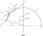
- Fig. 8 diagrammatically shows a mudguard with a shape which follows a substantially circular arch and has a centre (C). The rear side of the mudguard is situated on the left-hand side in the figure.
- the mudguard (1) is in an installation position, in which the installation angle ( ⁇ ) between, on the one hand, a horizontal line through the centre (C) and, on the other hand, a line which connects the rear end edge (20) of the mudguard (1) to the centre (C) is relatively small, in the order of magnitude of 10°, but this angle may also be greater, such as approximately 25° or more, or for example may be at least approximately 30° or approximately 45°. In a particular embodiment, this is for example at least 50°, such as for example at least 55°, 56°, 57°, 58° of 59°.
- the angle ( ⁇ 1) of the first tangent plane (R1) is approximately 60° and the angle ( ⁇ 2) of the second tangent plane (R2) is approximately 20°. In a more preferred embodiment, the angle ( ⁇ 2) of the second tangent plane (R2) is preferably approximately 40°.
- a respective normal line (N1), (N2) runs through the centre (C) and through each of the two points of contact where the tangent planes (R1), (R2) touch the mudguard, and forms a respective angle (90- ⁇ 1), (90- ⁇ 2) with a vertical line through the centre (C).
- the illumination surface (8) of the translucent wall (5) projects above a tangent plane (R1), (R2) which forms an angle ( ⁇ ) of between 20° and 60° with respect to a vertical surface (V1), (V2).
Landscapes
- Engineering & Computer Science (AREA)
- Mechanical Engineering (AREA)
- Lighting Device Outwards From Vehicle And Optical Signal (AREA)
- Non-Portable Lighting Devices Or Systems Thereof (AREA)
Claims (14)
- Fahrrad, umfassend ein Fahrradschutzblech (1), bereitgestellt mit einer Rücklichtvorrichtung, wobei die Rücklichtvorrichtung ein Gehäuse (2) umfasst, das in das Schutzblech integriert ist, wobei das Gehäuse (2) eine obere Schale (4) und eine untere Schale (7) umfasst, die über ihre angrenzenden Kanten zusammengebaut werden, um eine Einheit zu bilden, die einen inneren Raum umschließt, in dem zumindest eine Lichtquelle (3) bereitgestellt ist, wobei das Gehäuse (2) in einer quer verlaufenden Öffnung im Schutzblech (1) bereitgestellt ist und die obere Schale (4) eine durchscheinende Wand (5), die eine konvexe Wand (5) ist, die bei Verwendung eine Beleuchtungsoberfläche (8) bildet, und einen angrenzenden Teil (6) umfasst, und wobei die Form und die Abmessungen der peripheren Kante (5a) der durchscheinenden Wand (5) der Form und den Abmessungen der Öffnung im Schutzblech (1) entsprechen, sodass die periphere Kante (5a) der durchscheinenden Wand (5) eng an die Kanten der Öffnung angrenzt, wobei die durchscheinende Wand (5) eine Beleuchtungsoberfläche (8) bildet, die aus der Oberfläche des Schutzblechs herausragt, dass die Beleuchtungsoberfläche (8) im Wesentlichen der Krümmung des Schutzblechs (1) folgt und dass, in der Einbauposition des Schutzblechs gesehen, die Beleuchtungsoberfläche über eine Tangentialebene (R) an der Oberfläche des Schutzblechs herausragt, die einen Winkel (α) bezüglich einer vertikalen Ebene bildet, der mindestens 20° und höchstens 60° ist und wobei• die durchscheinende Wand (5) aus einem durchscheinenden Kunststoff gefertigt ist und der angrenzende Teil (6) aus dem gleichen durchscheinenden Kunststoff oder einem anderen, nicht durchscheinenden Kunststoff gefertigt ist;• die Öffnung das Schutzblech (1) schneidet und das Gehäuse (2) in das Schutzblech (1) in einer Weise integriert ist, dass die konvexe Wand (5) in der Öffnung befindlich ist und über die Oberfläche des Schutzblechs an der Außenseite des Schutzblechs (1) herausragt, sodass das Gehäuse im Wesentlichen an der Innenseite des Schutzblechs (1) befindlich ist, die zum Hinterrad (10) des Fahrrads zeigt, während die konvexe Wand (5) aus der Oberfläche des Schutzblechs (1) an der Außenseite des Schutzblechs (1) herausragt.
- Fahrrad nach Anspruch 1, dadurch gekennzeichnet, dass, in der Einbauposition des Schutzblechs gesehen, die Beleuchtungsoberfläche über eine Tangentialebene (R) an der Oberfläche des Schutzblechs herausragt, die einen Winkel (α) bezüglich einer vertikalen Ebene bildet, der mindestens 40° ist.
- Fahrrad nach Anspruch 1 oder 2, dadurch gekennzeichnet, dass die Höhe, um die die Beleuchtungsoberfläche aus der Oberfläche des Schutzblechs herausragt, nicht mehr als 10 mm ist.
- Fahrrad nach einem der vorhergehenden Ansprüche, dadurch gekennzeichnet, dass die herausragende Beleuchtungsoberfläche (8), in der Einbauposition des Schutzblechs (1) gesehen, auf beiden Seiten eine Zone umfasst, die in der Richtung des Randes zur Oberfläche des Schutzblechs verläuft, sodass Licht in beiden lateralen Richtungen über diese Zonen abgestrahlt werden kann.
- Fahrrad nach einem der vorhergehenden Ansprüche, dadurch gekennzeichnet, dass die herausragende Beleuchtungsoberfläche (8), in der Einbauposition des Schutzblechs (1) gesehen, dazu ausgelegt ist, einen Strahl von Licht mit einem horizontalen Strahlwinkel von mindestens 180° zu emittieren.
- Fahrrad nach einem der vorhergehenden Ansprüche, dadurch gekennzeichnet, dass die Beleuchtungsoberfläche, auf der Seite, die zum oberen Ende des Schutzblechs (1) gerichtet ist, und in der Einbauposition des Schutzblechs (1) gesehen, eine Zone (A) umfasst, wo die Beleuchtungsoberfläche (8) in der Richtung von ihrer oberen Kante (9) zur Oberfläche des Schutzblechs verläuft.
- Fahrrad nach Anspruch 6, dadurch gekennzeichnet, dass, in der Einbauposition des Schutzblechs (1) gesehen, die Zone (A) dazu ausgelegt ist, Licht in eine Aufwärtsrichtung zu emittieren, die, in der vertikalen Symmetrieebene entsprechend der Längsrichtung des Schutzblechs (1), von der Zone (A) schräg nach oben verläuft und sich der quer verlaufenden Ebene annähert, die durch das obere Ende des Schutzblechs (1) verläuft.
- Fahrrad nach Anspruch 6 oder 7, dadurch gekennzeichnet, dass das nach oben emittierte Licht eine Leuchtstärke von mindestens 0,025 cd aufweist.
- Fahrrad nach einem der vorhergehenden Ansprüche, dadurch gekennzeichnet, dass die Beleuchtungsoberfläche (8) dazu ausgelegt ist, in der Einbauposition des Schutzblechs (1), einen Strahl von Licht mit einer Leuchtstärkeverteilung bezüglich einer vertikalen Bezugsebene und einer horizontalen Bezugsebene mit einer gemeinsamen Schnittlinie zu emittieren, die mit der Hauptachse des Strahls von Licht zusammenfällt, gemäß dem die Leuchtstärke des Lichts, das in die Richtungen emittiert wird, die einen horizontalen Winkel von 20° bezüglich der vertikalen Bezugsebene bilden und einen vertikalen Winkel von 5° bezüglich der horizontalen Bezugsebene bilden, mindestens 10 % der Leuchtstärke des Lichts beträgt, das entlang der Hauptachse emittiert wird.
- Fahrrad nach einem der vorhergehenden Ansprüche, dadurch gekennzeichnet, dass die Beleuchtungsoberfläche (8) dazu ausgelegt ist, in der Einbauposition des Schutzblechs (1), einen Strahl von Licht mit einer Leuchtstärkeverteilung bezüglich einer vertikalen Bezugsebene und einer horizontalen Bezugsebene mit einer gemeinsamen Schnittlinie zu emittieren, die mit der Hauptachse des Strahls von Licht zusammenfällt, gemäß dem die Leuchtstärke des Lichts, das in die Richtungen emittiert wird, die einen horizontalen Winkel von 5° bezüglich der vertikalen Bezugsebene bilden und einen vertikalen Winkel von 10° bezüglich der horizontalen Bezugsebene bilden, mindestens 20 % der Leuchtstärke des Lichts beträgt, das entlang der Hauptachse emittiert wird.
- Fahrrad nach einem der vorhergehenden Ansprüche, dadurch gekennzeichnet, dass die Lichtquelle (3) zumindest eine LED umfasst.
- Fahrrad nach einem der vorhergehenden Ansprüche, dadurch gekennzeichnet, dass die Ausrichtung der Lichtquelle (3) einstellbar ist.
- Fahrrad nach einem der vorhergehenden Ansprüche, dadurch gekennzeichnet, dass das Gehäuse (2) Mittel zum Modifizieren der Richtung des Lichts, das durch die Lichtquelle (3) emittiert wird, und/oder zum Zerstreuen des Lichts umfasst.
- Fahrrad nach einem der vorhergehenden Ansprüche, dadurch gekennzeichnet, dass das Schutzblech (1) eine Sandwichstruktur aufweist, wobei zwei elektrisch leitfähige Schichten (1a), (1b) voneinander durch eine elektrisch isolierende Zwischenschicht (1c) getrennt werden, wobei das Gehäuse (2) mit dem Schutzblech (1) mittels eines elektrisch leitfähigen Verbindungsmittels (13), (14) verbunden ist, das das Schutzblech (1) schneidet, und dadurch, dass das Verbindungsmittel (13), (14) in diesem Fall eine elektrische Verbindung zwischen einer elektrisch leitfähigen Schicht (1a), (1b) des Schutzblechs (1) und einen Kontaktpunkt für Leistungsversorgung für eine oder mehrere elektrische oder elektronische Komponenten der Rücklichtvorrichtung bildet.
Applications Claiming Priority (1)
| Application Number | Priority Date | Filing Date | Title |
|---|---|---|---|
| BE2014/0093A BE1021326B1 (nl) | 2014-02-12 | 2014-02-12 | Fietsspatbord voorzien van een achterlichtinrichting. |
Publications (2)
| Publication Number | Publication Date |
|---|---|
| EP2907733A1 EP2907733A1 (de) | 2015-08-19 |
| EP2907733B1 true EP2907733B1 (de) | 2021-08-25 |
Family
ID=50630535
Family Applications (1)
| Application Number | Title | Priority Date | Filing Date |
|---|---|---|---|
| EP15154918.5A Active EP2907733B1 (de) | 2014-02-12 | 2015-02-12 | Fahrradschutzblech mit Rücklichtvorrichtung |
Country Status (4)
| Country | Link |
|---|---|
| EP (1) | EP2907733B1 (de) |
| BE (1) | BE1021326B1 (de) |
| DE (1) | DE202015001028U1 (de) |
| DK (1) | DK2907733T3 (de) |
Cited By (1)
| Publication number | Priority date | Publication date | Assignee | Title |
|---|---|---|---|---|
| TWI868619B (zh) * | 2023-03-13 | 2025-01-01 | 廖以誌 | 自行車尾燈複合裝置 |
Families Citing this family (3)
| Publication number | Priority date | Publication date | Assignee | Title |
|---|---|---|---|---|
| SE540687C2 (en) * | 2016-06-15 | 2018-10-09 | Scania Cv Ab | Windshield wiper device, and a method for wiping a windshield |
| IT202000002335A1 (it) * | 2020-02-06 | 2021-08-06 | M A S Medical Analitical Service Di Molinari Giorgio E C Snc | Parafango luminoso per ruote di veicoli e relativo processo di fabbricazione |
| DE202020101524U1 (de) | 2020-03-20 | 2020-03-31 | MPR GmbH & Co. KG | Radschützer mit Rücklicht sowie Rücklicht für ein Zweirad |
Citations (1)
| Publication number | Priority date | Publication date | Assignee | Title |
|---|---|---|---|---|
| TW201404646A (zh) * | 2012-07-24 | 2014-02-01 | Topeak Inc | 具尾燈功能之導光泥除 |
Family Cites Families (13)
| Publication number | Priority date | Publication date | Assignee | Title |
|---|---|---|---|---|
| FR1053465A (fr) * | 1951-07-07 | 1954-02-02 | Procédé pour la signalisation nocturne des cyclistes et lampe de sécurité pour sa réalisation | |
| CH497999A (de) * | 1968-10-08 | 1970-10-31 | Heinrich Benzing Praez S Dreht | Radschmutzfänger, insbesondere für Zweiräder, mit aus Kunststoff bestehendem Rinnenkörper |
| FR2608254B1 (fr) * | 1986-12-10 | 1991-04-12 | Cipel | Dispositif d'eclairage pour bicyclette |
| CH682142A5 (de) * | 1992-04-14 | 1993-07-30 | Ver Drahtwerke Ag | |
| DE19618070A1 (de) * | 1996-05-06 | 1997-11-13 | Chuang Hsien Ting | Kunststoff-Schutzblech für Fahrräder oder Motorräder und Verfahren zur Herstellung desselben |
| DE20114617U1 (de) | 2001-09-05 | 2001-10-31 | H. Hemmelskamp GmbH & Co KG, 33617 Bielefeld | Mit einer Beleuchtungseinrichtung versehenes Schutzblech für ein Zweirad |
| JP4302444B2 (ja) * | 2003-06-24 | 2009-07-29 | 本田技研工業株式会社 | テールライト構造 |
| JP4562499B2 (ja) * | 2004-11-18 | 2010-10-13 | 株式会社キャットアイ | リフレクタおよび自転車 |
| DE202009004770U1 (de) * | 2009-04-30 | 2009-09-17 | Chen Whua International Co., Ltd., Yongkang City | Schutzblech mit einer Warnleuchte |
| CN101718400A (zh) * | 2009-12-11 | 2010-06-02 | 深圳市众明半导体照明有限公司 | 一种大角度led照明装置 |
| FR2975661B1 (fr) * | 2011-05-25 | 2013-06-28 | Peugeot Citroen Automobiles Sa | Garde-boue de roue pour vehicule et vehicule dont les roues sont pourvues d'un tel garde-boue |
| CN202827882U (zh) * | 2012-09-24 | 2013-03-27 | 极点股份有限公司 | 具有尾灯功能的导光挡泥板 |
| DE202013003875U1 (de) | 2013-04-24 | 2013-05-13 | Cho-Ten Chiu | Kotflügel für Fahrrad |
-
2014
- 2014-02-12 BE BE2014/0093A patent/BE1021326B1/nl active
-
2015
- 2015-02-12 EP EP15154918.5A patent/EP2907733B1/de active Active
- 2015-02-12 DK DK15154918.5T patent/DK2907733T3/da active
- 2015-02-12 DE DE202015001028.8U patent/DE202015001028U1/de not_active Expired - Lifetime
Patent Citations (1)
| Publication number | Priority date | Publication date | Assignee | Title |
|---|---|---|---|---|
| TW201404646A (zh) * | 2012-07-24 | 2014-02-01 | Topeak Inc | 具尾燈功能之導光泥除 |
Non-Patent Citations (1)
| Title |
|---|
| ADMIN: "Topeak wins IF Eurobike Award 2013 for DeFender(TM) iGlow X. | BaikBike.com", 27 August 2013 (2013-08-27), XP055272762, Retrieved from the Internet <URL:http://www.baikbike.com/topeak-wins-if-eurobike-award-2013-for-defender-iglow-x/> [retrieved on 20160513] * |
Cited By (1)
| Publication number | Priority date | Publication date | Assignee | Title |
|---|---|---|---|---|
| TWI868619B (zh) * | 2023-03-13 | 2025-01-01 | 廖以誌 | 自行車尾燈複合裝置 |
Also Published As
| Publication number | Publication date |
|---|---|
| EP2907733A1 (de) | 2015-08-19 |
| DE202015001028U1 (de) | 2015-05-18 |
| DK2907733T3 (da) | 2021-11-15 |
| BE1021326B1 (nl) | 2015-10-29 |
Similar Documents
| Publication | Publication Date | Title |
|---|---|---|
| ES2822448T3 (es) | Aplique de iluminación | |
| US8256943B2 (en) | Vehicle light | |
| EP2907733A1 (de) | Fahrradschutzblech mit rücklichtvorrichtung | |
| US20210239282A1 (en) | Accent light assembly | |
| KR100951650B1 (ko) | 엘이디 조명장치 | |
| US7722231B2 (en) | Bicycle safety lighting | |
| KR20110085868A (ko) | 차량용 등기구의 반도체형 광원의 광원 유닛, 차량용 등기구 | |
| JP2012022797A (ja) | 車両用灯具の半導体型光源の光源ユニット、車両用灯具 | |
| US8783924B1 (en) | Wide angle illumination assembly and reflector therefor | |
| US6840661B2 (en) | Flush fitting LED turn signal | |
| US7108407B2 (en) | Rear fender integrated tail lamp device for motorcycle | |
| EP1920973A2 (de) | Beleuchtungssystem für eine Kraftfahrzeugregistrierplatte | |
| JP3126643U (ja) | 照明器具を具えた自転車のフレーム | |
| ES2476015T3 (es) | Luz trasera y motocicleta | |
| JP3203863U (ja) | 照光制御されたライトを有する自転車サドル | |
| KR101136003B1 (ko) | 아치형 하우징 및 그를 이용한 조명장치 | |
| US20090086499A1 (en) | Car spoiler having light-emitting effect | |
| EP2998646A1 (de) | Scheinwerfer für fahrzeug | |
| US20220404009A1 (en) | Underwater led lamp | |
| ES2690756T3 (es) | Faro de combinación trasero para uso en vehículo, y vehículo | |
| EP1403167A1 (de) | Lenkradverkleidung mit dekorativer Beleuchtung | |
| JP2011253774A (ja) | 車両用灯具の半導体型光源の光源ユニット、車両用灯具 | |
| JPS61171177A (ja) | Led光源体 | |
| JP6784990B2 (ja) | 照明器具 | |
| JPH04229502A (ja) | Ledモジュール |
Legal Events
| Date | Code | Title | Description |
|---|---|---|---|
| PUAI | Public reference made under article 153(3) epc to a published international application that has entered the european phase |
Free format text: ORIGINAL CODE: 0009012 |
|
| AK | Designated contracting states |
Kind code of ref document: A1 Designated state(s): AL AT BE BG CH CY CZ DE DK EE ES FI FR GB GR HR HU IE IS IT LI LT LU LV MC MK MT NL NO PL PT RO RS SE SI SK SM TR |
|
| AX | Request for extension of the european patent |
Extension state: BA ME |
|
| 17P | Request for examination filed |
Effective date: 20160219 |
|
| RBV | Designated contracting states (corrected) |
Designated state(s): AL AT BE BG CH CY CZ DE DK EE ES FI FR GB GR HR HU IE IS IT LI LT LU LV MC MK MT NL NO PL PT RO RS SE SI SK SM TR |
|
| 17Q | First examination report despatched |
Effective date: 20160531 |
|
| STAA | Information on the status of an ep patent application or granted ep patent |
Free format text: STATUS: EXAMINATION IS IN PROGRESS |
|
| GRAP | Despatch of communication of intention to grant a patent |
Free format text: ORIGINAL CODE: EPIDOSNIGR1 |
|
| STAA | Information on the status of an ep patent application or granted ep patent |
Free format text: STATUS: GRANT OF PATENT IS INTENDED |
|
| INTG | Intention to grant announced |
Effective date: 20210125 |
|
| GRAJ | Information related to disapproval of communication of intention to grant by the applicant or resumption of examination proceedings by the epo deleted |
Free format text: ORIGINAL CODE: EPIDOSDIGR1 |
|
| STAA | Information on the status of an ep patent application or granted ep patent |
Free format text: STATUS: EXAMINATION IS IN PROGRESS |
|
| GRAP | Despatch of communication of intention to grant a patent |
Free format text: ORIGINAL CODE: EPIDOSNIGR1 |
|
| STAA | Information on the status of an ep patent application or granted ep patent |
Free format text: STATUS: GRANT OF PATENT IS INTENDED |
|
| INTC | Intention to grant announced (deleted) | ||
| GRAS | Grant fee paid |
Free format text: ORIGINAL CODE: EPIDOSNIGR3 |
|
| INTG | Intention to grant announced |
Effective date: 20210625 |
|
| GRAA | (expected) grant |
Free format text: ORIGINAL CODE: 0009210 |
|
| STAA | Information on the status of an ep patent application or granted ep patent |
Free format text: STATUS: THE PATENT HAS BEEN GRANTED |
|
| AK | Designated contracting states |
Kind code of ref document: B1 Designated state(s): AL AT BE BG CH CY CZ DE DK EE ES FI FR GB GR HR HU IE IS IT LI LT LU LV MC MK MT NL NO PL PT RO RS SE SI SK SM TR |
|
| REG | Reference to a national code |
Ref country code: CH Ref legal event code: EP |
|
| REG | Reference to a national code |
Ref country code: DE Ref legal event code: R096 Ref document number: 602015072534 Country of ref document: DE |
|
| REG | Reference to a national code |
Ref country code: IE Ref legal event code: FG4D Ref country code: AT Ref legal event code: REF Ref document number: 1423539 Country of ref document: AT Kind code of ref document: T Effective date: 20210915 |
|
| REG | Reference to a national code |
Ref country code: DK Ref legal event code: T3 Effective date: 20211111 |
|
| REG | Reference to a national code |
Ref country code: LT Ref legal event code: MG9D |
|
| REG | Reference to a national code |
Ref country code: NL Ref legal event code: FP |
|
| REG | Reference to a national code |
Ref country code: AT Ref legal event code: MK05 Ref document number: 1423539 Country of ref document: AT Kind code of ref document: T Effective date: 20210825 |
|
| PG25 | Lapsed in a contracting state [announced via postgrant information from national office to epo] |
Ref country code: BG Free format text: LAPSE BECAUSE OF FAILURE TO SUBMIT A TRANSLATION OF THE DESCRIPTION OR TO PAY THE FEE WITHIN THE PRESCRIBED TIME-LIMIT Effective date: 20211125 Ref country code: AT Free format text: LAPSE BECAUSE OF FAILURE TO SUBMIT A TRANSLATION OF THE DESCRIPTION OR TO PAY THE FEE WITHIN THE PRESCRIBED TIME-LIMIT Effective date: 20210825 Ref country code: LT Free format text: LAPSE BECAUSE OF FAILURE TO SUBMIT A TRANSLATION OF THE DESCRIPTION OR TO PAY THE FEE WITHIN THE PRESCRIBED TIME-LIMIT Effective date: 20210825 Ref country code: FI Free format text: LAPSE BECAUSE OF FAILURE TO SUBMIT A TRANSLATION OF THE DESCRIPTION OR TO PAY THE FEE WITHIN THE PRESCRIBED TIME-LIMIT Effective date: 20210825 Ref country code: ES Free format text: LAPSE BECAUSE OF FAILURE TO SUBMIT A TRANSLATION OF THE DESCRIPTION OR TO PAY THE FEE WITHIN THE PRESCRIBED TIME-LIMIT Effective date: 20210825 Ref country code: PT Free format text: LAPSE BECAUSE OF FAILURE TO SUBMIT A TRANSLATION OF THE DESCRIPTION OR TO PAY THE FEE WITHIN THE PRESCRIBED TIME-LIMIT Effective date: 20211227 Ref country code: NO Free format text: LAPSE BECAUSE OF FAILURE TO SUBMIT A TRANSLATION OF THE DESCRIPTION OR TO PAY THE FEE WITHIN THE PRESCRIBED TIME-LIMIT Effective date: 20211125 Ref country code: RS Free format text: LAPSE BECAUSE OF FAILURE TO SUBMIT A TRANSLATION OF THE DESCRIPTION OR TO PAY THE FEE WITHIN THE PRESCRIBED TIME-LIMIT Effective date: 20210825 Ref country code: SE Free format text: LAPSE BECAUSE OF FAILURE TO SUBMIT A TRANSLATION OF THE DESCRIPTION OR TO PAY THE FEE WITHIN THE PRESCRIBED TIME-LIMIT Effective date: 20210825 Ref country code: HR Free format text: LAPSE BECAUSE OF FAILURE TO SUBMIT A TRANSLATION OF THE DESCRIPTION OR TO PAY THE FEE WITHIN THE PRESCRIBED TIME-LIMIT Effective date: 20210825 |
|
| PG25 | Lapsed in a contracting state [announced via postgrant information from national office to epo] |
Ref country code: PL Free format text: LAPSE BECAUSE OF FAILURE TO SUBMIT A TRANSLATION OF THE DESCRIPTION OR TO PAY THE FEE WITHIN THE PRESCRIBED TIME-LIMIT Effective date: 20210825 Ref country code: LV Free format text: LAPSE BECAUSE OF FAILURE TO SUBMIT A TRANSLATION OF THE DESCRIPTION OR TO PAY THE FEE WITHIN THE PRESCRIBED TIME-LIMIT Effective date: 20210825 Ref country code: GR Free format text: LAPSE BECAUSE OF FAILURE TO SUBMIT A TRANSLATION OF THE DESCRIPTION OR TO PAY THE FEE WITHIN THE PRESCRIBED TIME-LIMIT Effective date: 20211126 |
|
| REG | Reference to a national code |
Ref country code: DE Ref legal event code: R097 Ref document number: 602015072534 Country of ref document: DE |
|
| PG25 | Lapsed in a contracting state [announced via postgrant information from national office to epo] |
Ref country code: SM Free format text: LAPSE BECAUSE OF FAILURE TO SUBMIT A TRANSLATION OF THE DESCRIPTION OR TO PAY THE FEE WITHIN THE PRESCRIBED TIME-LIMIT Effective date: 20210825 Ref country code: SK Free format text: LAPSE BECAUSE OF FAILURE TO SUBMIT A TRANSLATION OF THE DESCRIPTION OR TO PAY THE FEE WITHIN THE PRESCRIBED TIME-LIMIT Effective date: 20210825 Ref country code: RO Free format text: LAPSE BECAUSE OF FAILURE TO SUBMIT A TRANSLATION OF THE DESCRIPTION OR TO PAY THE FEE WITHIN THE PRESCRIBED TIME-LIMIT Effective date: 20210825 Ref country code: EE Free format text: LAPSE BECAUSE OF FAILURE TO SUBMIT A TRANSLATION OF THE DESCRIPTION OR TO PAY THE FEE WITHIN THE PRESCRIBED TIME-LIMIT Effective date: 20210825 Ref country code: AL Free format text: LAPSE BECAUSE OF FAILURE TO SUBMIT A TRANSLATION OF THE DESCRIPTION OR TO PAY THE FEE WITHIN THE PRESCRIBED TIME-LIMIT Effective date: 20210825 |
|
| PLBE | No opposition filed within time limit |
Free format text: ORIGINAL CODE: 0009261 |
|
| STAA | Information on the status of an ep patent application or granted ep patent |
Free format text: STATUS: NO OPPOSITION FILED WITHIN TIME LIMIT |
|
| PG25 | Lapsed in a contracting state [announced via postgrant information from national office to epo] |
Ref country code: IT Free format text: LAPSE BECAUSE OF FAILURE TO SUBMIT A TRANSLATION OF THE DESCRIPTION OR TO PAY THE FEE WITHIN THE PRESCRIBED TIME-LIMIT Effective date: 20210825 |
|
| 26N | No opposition filed |
Effective date: 20220527 |
|
| PG25 | Lapsed in a contracting state [announced via postgrant information from national office to epo] |
Ref country code: SI Free format text: LAPSE BECAUSE OF FAILURE TO SUBMIT A TRANSLATION OF THE DESCRIPTION OR TO PAY THE FEE WITHIN THE PRESCRIBED TIME-LIMIT Effective date: 20210825 |
|
| PG25 | Lapsed in a contracting state [announced via postgrant information from national office to epo] |
Ref country code: MC Free format text: LAPSE BECAUSE OF FAILURE TO SUBMIT A TRANSLATION OF THE DESCRIPTION OR TO PAY THE FEE WITHIN THE PRESCRIBED TIME-LIMIT Effective date: 20210825 |
|
| PG25 | Lapsed in a contracting state [announced via postgrant information from national office to epo] |
Ref country code: LU Free format text: LAPSE BECAUSE OF NON-PAYMENT OF DUE FEES Effective date: 20220212 |
|
| PG25 | Lapsed in a contracting state [announced via postgrant information from national office to epo] |
Ref country code: IE Free format text: LAPSE BECAUSE OF NON-PAYMENT OF DUE FEES Effective date: 20220212 |
|
| PG25 | Lapsed in a contracting state [announced via postgrant information from national office to epo] |
Ref country code: HU Free format text: LAPSE BECAUSE OF FAILURE TO SUBMIT A TRANSLATION OF THE DESCRIPTION OR TO PAY THE FEE WITHIN THE PRESCRIBED TIME-LIMIT; INVALID AB INITIO Effective date: 20150212 |
|
| PG25 | Lapsed in a contracting state [announced via postgrant information from national office to epo] |
Ref country code: MK Free format text: LAPSE BECAUSE OF FAILURE TO SUBMIT A TRANSLATION OF THE DESCRIPTION OR TO PAY THE FEE WITHIN THE PRESCRIBED TIME-LIMIT Effective date: 20210825 Ref country code: CY Free format text: LAPSE BECAUSE OF FAILURE TO SUBMIT A TRANSLATION OF THE DESCRIPTION OR TO PAY THE FEE WITHIN THE PRESCRIBED TIME-LIMIT Effective date: 20210825 |
|
| PG25 | Lapsed in a contracting state [announced via postgrant information from national office to epo] |
Ref country code: MT Free format text: LAPSE BECAUSE OF FAILURE TO SUBMIT A TRANSLATION OF THE DESCRIPTION OR TO PAY THE FEE WITHIN THE PRESCRIBED TIME-LIMIT Effective date: 20210825 |
|
| PG25 | Lapsed in a contracting state [announced via postgrant information from national office to epo] |
Ref country code: TR Free format text: LAPSE BECAUSE OF FAILURE TO SUBMIT A TRANSLATION OF THE DESCRIPTION OR TO PAY THE FEE WITHIN THE PRESCRIBED TIME-LIMIT Effective date: 20210825 |
|
| PGFP | Annual fee paid to national office [announced via postgrant information from national office to epo] |
Ref country code: NL Payment date: 20251226 Year of fee payment: 12 |
|
| PGFP | Annual fee paid to national office [announced via postgrant information from national office to epo] |
Ref country code: BE Payment date: 20251215 Year of fee payment: 12 |
|
| REG | Reference to a national code |
Ref country code: CH Ref legal event code: U11 Free format text: ST27 STATUS EVENT CODE: U-0-0-U10-U11 (AS PROVIDED BY THE NATIONAL OFFICE) Effective date: 20260301 |
|
| REG | Reference to a national code |
Ref country code: DE Ref legal event code: R081 Ref document number: 602015072534 Country of ref document: DE Owner name: CURANA BV, BE Free format text: FORMER OWNER: CURANA INVEST BVBA, ARDOOIE, BE Ref country code: DE Ref legal event code: R082 Ref document number: 602015072534 Country of ref document: DE Representative=s name: HERNANDEZ, YORCK, DIPL.-ING., DE |
|
| REG | Reference to a national code |
Ref country code: CH Ref legal event code: R14 Free format text: ST27 STATUS EVENT CODE: U-0-0-R10-R14 (AS PROVIDED BY THE NATIONAL OFFICE) Effective date: 20260317 Ref country code: CH Ref legal event code: R17 Free format text: ST27 STATUS EVENT CODE: U-0-0-R10-R17 (AS PROVIDED BY THE NATIONAL OFFICE) Effective date: 20260317 |
|
| PGFP | Annual fee paid to national office [announced via postgrant information from national office to epo] |
Ref country code: GB Payment date: 20260219 Year of fee payment: 12 |
|
| PGFP | Annual fee paid to national office [announced via postgrant information from national office to epo] |
Ref country code: DE Payment date: 20260218 Year of fee payment: 12 Ref country code: DK Payment date: 20260220 Year of fee payment: 12 |
|
| PGFP | Annual fee paid to national office [announced via postgrant information from national office to epo] |
Ref country code: FR Payment date: 20260218 Year of fee payment: 12 |
|
| REG | Reference to a national code |
Ref country code: GB Ref legal event code: 732E Free format text: REGISTERED BETWEEN 20260326 AND 20260401 |
|
| PGFP | Annual fee paid to national office [announced via postgrant information from national office to epo] |
Ref country code: CH Payment date: 20260301 Year of fee payment: 12 Ref country code: CZ Payment date: 20260204 Year of fee payment: 12 |