EP2906364B1 - Procédé de commande d'une installation de traitement d'un matériau minéral et installation de traitement d'un matériau minéral - Google Patents
Procédé de commande d'une installation de traitement d'un matériau minéral et installation de traitement d'un matériau minéral Download PDFInfo
- Publication number
- EP2906364B1 EP2906364B1 EP13795541.5A EP13795541A EP2906364B1 EP 2906364 B1 EP2906364 B1 EP 2906364B1 EP 13795541 A EP13795541 A EP 13795541A EP 2906364 B1 EP2906364 B1 EP 2906364B1
- Authority
- EP
- European Patent Office
- Prior art keywords
- mineral material
- processing plant
- plant
- material processing
- stand
- Prior art date
- Legal status (The legal status is an assumption and is not a legal conclusion. Google has not performed a legal analysis and makes no representation as to the accuracy of the status listed.)
- Active
Links
- 239000000463 material Substances 0.000 title claims description 144
- 229910052500 inorganic mineral Inorganic materials 0.000 title claims description 96
- 239000011707 mineral Substances 0.000 title claims description 96
- 238000012545 processing Methods 0.000 title claims description 82
- 238000000034 method Methods 0.000 title claims description 57
- 230000008569 process Effects 0.000 claims description 48
- 230000004044 response Effects 0.000 claims description 5
- 238000005259 measurement Methods 0.000 description 17
- 230000008859 change Effects 0.000 description 10
- 230000008901 benefit Effects 0.000 description 6
- 239000000203 mixture Substances 0.000 description 5
- 238000005265 energy consumption Methods 0.000 description 4
- 238000005516 engineering process Methods 0.000 description 4
- 230000003287 optical effect Effects 0.000 description 3
- 230000005855 radiation Effects 0.000 description 3
- 239000004575 stone Substances 0.000 description 3
- 238000002604 ultrasonography Methods 0.000 description 3
- 241000446313 Lamella Species 0.000 description 2
- 238000010276 construction Methods 0.000 description 2
- 238000004519 manufacturing process Methods 0.000 description 2
- 238000012805 post-processing Methods 0.000 description 2
- 239000002699 waste material Substances 0.000 description 2
- 230000009471 action Effects 0.000 description 1
- 230000000903 blocking effect Effects 0.000 description 1
- 238000001816 cooling Methods 0.000 description 1
- 230000001186 cumulative effect Effects 0.000 description 1
- 230000001419 dependent effect Effects 0.000 description 1
- 238000009826 distribution Methods 0.000 description 1
- 230000007613 environmental effect Effects 0.000 description 1
- 239000010720 hydraulic oil Substances 0.000 description 1
- 230000006872 improvement Effects 0.000 description 1
- 239000000314 lubricant Substances 0.000 description 1
- 239000002184 metal Substances 0.000 description 1
- 238000002360 preparation method Methods 0.000 description 1
- 230000002265 prevention Effects 0.000 description 1
- 230000008929 regeneration Effects 0.000 description 1
- 238000011069 regeneration method Methods 0.000 description 1
- 230000011664 signaling Effects 0.000 description 1
- XLYOFNOQVPJJNP-UHFFFAOYSA-N water Substances O XLYOFNOQVPJJNP-UHFFFAOYSA-N 0.000 description 1
Images

Classifications
-
- B—PERFORMING OPERATIONS; TRANSPORTING
- B02—CRUSHING, PULVERISING, OR DISINTEGRATING; PREPARATORY TREATMENT OF GRAIN FOR MILLING
- B02C—CRUSHING, PULVERISING, OR DISINTEGRATING IN GENERAL; MILLING GRAIN
- B02C25/00—Control arrangements specially adapted for crushing or disintegrating
-
- B—PERFORMING OPERATIONS; TRANSPORTING
- B07—SEPARATING SOLIDS FROM SOLIDS; SORTING
- B07B—SEPARATING SOLIDS FROM SOLIDS BY SIEVING, SCREENING, SIFTING OR BY USING GAS CURRENTS; SEPARATING BY OTHER DRY METHODS APPLICABLE TO BULK MATERIAL, e.g. LOOSE ARTICLES FIT TO BE HANDLED LIKE BULK MATERIAL
- B07B13/00—Grading or sorting solid materials by dry methods, not otherwise provided for; Sorting articles otherwise than by indirectly controlled devices
- B07B13/14—Details or accessories
- B07B13/18—Control
-
- B—PERFORMING OPERATIONS; TRANSPORTING
- B02—CRUSHING, PULVERISING, OR DISINTEGRATING; PREPARATORY TREATMENT OF GRAIN FOR MILLING
- B02C—CRUSHING, PULVERISING, OR DISINTEGRATING IN GENERAL; MILLING GRAIN
- B02C21/00—Disintegrating plant with or without drying of the material
- B02C21/02—Transportable disintegrating plant
-
- B—PERFORMING OPERATIONS; TRANSPORTING
- B07—SEPARATING SOLIDS FROM SOLIDS; SORTING
- B07B—SEPARATING SOLIDS FROM SOLIDS BY SIEVING, SCREENING, SIFTING OR BY USING GAS CURRENTS; SEPARATING BY OTHER DRY METHODS APPLICABLE TO BULK MATERIAL, e.g. LOOSE ARTICLES FIT TO BE HANDLED LIKE BULK MATERIAL
- B07B1/00—Sieving, screening, sifting, or sorting solid materials using networks, gratings, grids, or the like
- B07B1/42—Drive mechanisms, regulating or controlling devices, or balancing devices, specially adapted for screens
-
- B—PERFORMING OPERATIONS; TRANSPORTING
- B07—SEPARATING SOLIDS FROM SOLIDS; SORTING
- B07B—SEPARATING SOLIDS FROM SOLIDS BY SIEVING, SCREENING, SIFTING OR BY USING GAS CURRENTS; SEPARATING BY OTHER DRY METHODS APPLICABLE TO BULK MATERIAL, e.g. LOOSE ARTICLES FIT TO BE HANDLED LIKE BULK MATERIAL
- B07B13/00—Grading or sorting solid materials by dry methods, not otherwise provided for; Sorting articles otherwise than by indirectly controlled devices
- B07B13/14—Details or accessories
- B07B13/16—Feed or discharge arrangements
-
- Y—GENERAL TAGGING OF NEW TECHNOLOGICAL DEVELOPMENTS; GENERAL TAGGING OF CROSS-SECTIONAL TECHNOLOGIES SPANNING OVER SEVERAL SECTIONS OF THE IPC; TECHNICAL SUBJECTS COVERED BY FORMER USPC CROSS-REFERENCE ART COLLECTIONS [XRACs] AND DIGESTS
- Y02—TECHNOLOGIES OR APPLICATIONS FOR MITIGATION OR ADAPTATION AGAINST CLIMATE CHANGE
- Y02W—CLIMATE CHANGE MITIGATION TECHNOLOGIES RELATED TO WASTEWATER TREATMENT OR WASTE MANAGEMENT
- Y02W30/00—Technologies for solid waste management
- Y02W30/50—Reuse, recycling or recovery technologies
- Y02W30/58—Construction or demolition [C&D] waste
Definitions
- the invention relates to a method for controlling a mineral material processing plant and to a mineral material processing plant.
- the invention relates to a mobile mineral material processing plant and to controlling thereof.
- Mineral material such as stone
- Mineral material is retrieved to be crushed from the ground either by exploding or by digging.
- Mineral material may also comprise natural stone, gravel and construction waste.
- Both mobile crushers and fixed crusher applications are used for crushing.
- the material to be crushed is fed with an excavator or a wheel loader into a feed hopper of the crusher, from where the material to be crushed falls into the jaws of the crusher, or a feeder or a feeder device transfers the stone material towards the crusher.
- a mineral material processing plant comprises on or more crushers and/or screens and possibly further devices such as conveyors.
- the processing plant may be fixed or mobile.
- mobile processing plants are used in urban surroundings in processing recyclable material such as construction waste.
- An objective of the invention is to provide a mineral material processing plant the bringing of which into process run is easy, fast and safe.
- An objective of the invention is to provide a processing plant that can be kept running energy-economically.
- An objective of the invention is to enable a crushing or other processing time as long as possible.
- the need to switch off the stand-by mode is recognized by recognizing mineral material arriving to be processed.
- the mineral material on the feeder device is recognized by measuring the surface height of the mineral material on the feeder device of the mineral material processing plant
- the surface height of the mineral material on the feeder device of the mineral material processing plant is measured with an ultrasound sensor, an optical sensor and/or a radiation sensor.
- the mineral material on the feeder device is recognized by measuring the tension, force and/or pressure caused to the feeder device by the mineral material.
- the tension, force and/or pressure caused to the feeder device by the mineral material is measured with strain gauges, conveyor scale and/or pressure sensor.
- the mineral material on the feeder device is recognized from a video with image based measurement.
- the proximity to the feeder device of the mineral material processing plant of a machine or a part of the machine is recognized by satellite positioning.
- the proximity to the feeder device of the mineral material processing plant of a machine or a part of the machine is recognized from a video with image based measurement.
- the mineral material arriving to be processed is recognized based on measurement information received from an earlier processing phase.
- the mineral material arriving to be processed is recognized by recognizing an identifier placed among the mineral material.
- the mineral material on the feeder device of the mineral material processing plant is recognized, and the feeding of mineral material into the processing plant is enabled in response to recognizing the mineral material on the feeder device of the mineral material processing plant.
- the processing plant comprises a screen.
- the processing plant is one of the following; a fixed plant, a track-based plant, a wheel-based plant.
- the arrangement for recognizing the need to switch off a standby-mode comprises an arrangement for recognizing material arriving to be processed.
- the arrangement for recognizing mineral material on the feeder device comprises an arrangement for measuring the surface height of the material on the feeder device.
- the arrangement for measuring the surface height of the material on the feeder device comprises an ultrasound sensor, an optical sensor and/or a radiation sensor.
- the arrangement for recognizing mineral material on the feeder device comprises an arrangement for measuring the tension, force and/or pressure caused to the feeder device by the mineral material.
- the arrangement for measuring the tension, force and/or pressure caused to the feeder device by the mineral material comprises strain gauges, a conveyor scale and/or a pressure sensor.
- the arrangement for recognizing mineral material on the feeder device comprises an arrangement for recognizing mineral material on the feeder device from a video with image based measurement.
- the arrangement for recognizing the proximity to the feeder device of the mineral material processing plant of a machine or of a part of the machine used to bring the mineral material comprises a recognition arrangement based on satellite positioning.
- the arrangement for recognizing the proximity to the feeder device of the mineral material processing plant of a machine or of a part of the machine used to bring the mineral material comprises a recognition arrangement with image based measurement from a video image.
- the arrangement for recognizing the proximity to the feeder device of the mineral material processing plant of a machine or of a part of the machine used to bring the mineral material comprises an arrangement for recognizing the material arriving to be processed based on measurement information received from an earlier processing phase.
- the arrangement for recognizing material arriving to be processed comprises an arrangement for recognizing an identifier placed among the mineral material arriving to be processed.
- Fig. 1 shows a mobile track based mineral material processing plant 100 according to a preferred embodiment of the invention.
- Processing plant 100 comprises a frame 101, a track-base 102, a feeder 103 and a crusher 120, such as a cone-, jaw- or gyratory crusher.
- the crushing plant 100 further comprises a motor unit 104 for driving the crusher 120 and a conveyor for conveying the crushed material for example into a pile.
- the crusher 120 may be used as intermediate or post processing crusher. In particular crusher 120 may be used in fine crushing.
- the mobile crushing plant 100 may be movable also with other means, such as wheels, skids or legs.
- the crushing plant 100 may also be fixed.
- the feeder 103 may be of type of vibration feeder or a belt- or a lamella conveyor.
- the crushing plant 100 further comprises a control system 214 and a control unit 110 with which the crushing plant may be driven into a stand-by mode.
- the control unit 110 is in Fig. 1 shown separately from control system 214 for the sake of clarity, but the control unit 110 may be integrated into the control system 214.
- the crushing plant 100 further comprises manual operating switches 111 and 111' for the stand-by mode, which switches are connected to the control unit 110 either wirelessly or with a fixed connection. Alternatively, there is only one operating switch.
- the operating switch 111,111' may be arranged in such a way that it may be used either with a fixed or with a wireless connection.
- the crushing plant may be automatically driven to a stand-by mode and back to the process mode from the stand-by mode with a single push, or a like operating, of the switch.
- Driving the crushing plant to the stand-by mode or returning to the process mode by actuating the operating switch 111,111' requires a user of the crushing plant to evaluate the need for a change of mode and to manually engage the change of the mode.
- control unit 110 or the control system 214 comprises an arrangement with which the crushing plant 100 may be driven to process mode, i.e. returned from the stand-by mode automatically in a way hereinafter described.
- the control unit 110 or the control system 214 comprises, or is in connection with, the sensors and/or the like measurement arrangements used for the arrangement.
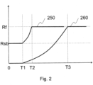
- Fig. 2 shows the functioning of the actuators of a mineral material processing plant 100 according to a preferred embodiment controlled by a method according to a preferred embodiment with the rotating speed of the motors(s) 104.
- the Fig. shows with a chart the driving of the crushing plant 100 into process speed after an interruption 260 and driving of the crushing plant 100 automatically into process speed from a stand-by mode according to a preferred embodiment 250.
- the vertical axis of the chart shown in Fig. 2 shows a rotating speed of an actuator or actuators and the horizontal axis shows time.
- the actuators of the crushing plant 100 are stopped and the motor 104 used to drive the plant is also stopped.
- the motor 104 used to drive the crushing plant may run on idle speed while actuators anyhow remain stopped.
- the motor 104 is a diesel motor or an electric motor.
- Process speed means the speed of the actuator which speed the actuator has when the crushing plant 100 is in process mode or process use, i.e. when the crushing plant 100 processes material and in which state the motor 104 of the crushing plant 100 is running with process speed Rf.
- a crushing plant 100 comprises more than one actuator, and depending on the purpose and composition of the crushing plant 100 there may be for example 12 or more actuators.
- actuators belonging to the composition of a crushing plant 100 are various conveyors, such as main conveyor and side conveyor; a conveyor with magnet for separating metal; a screen; a water pump; and a crusher. Due to the number of actuators, the starting sequence as hereinbefore explained and issues related thereto, the driving of the crushing plant 100 to the process speed takes a certain time depending on the composition of the plant, as can be seen from the chart 500 of Fig. 2 . The time needed for start T1...T3 may be several minutes.
- the time needed for start T1...T3 further causes the driving of the crushing plant 100 with process speed also when material to be processed is not fed into the crushing plant 100, especially if the time during which no material to be processed is fed is short.
- Continuous driving with process speed increases energy consumption, noise production and exposes components of the crushing plant 100 to wear.
- the crushing plant might be driven with process speed also when material to be processed is not fed into the crushing plant 100, especially if the time during which no material to be processed is fed is short.
- Stand-by mode means a state in which substantially all chosen actuators of the crushing plant 100 remain running at a reduced stand-by speed, or stand-by mode speed, or reduced power.
- this reduced speed is called stand-by speed.
- the stand-by speed may be different for each actuator, and such a speed that each actuator remains running.
- substantially all actuators remain running means that actuators substantially relating to the crushing process, i.e. actuators directly in touch with mineral material processing, remain mainly running in such a way that their driving to process speed is quickened.
- a part of the actuators of the crushing plant 100 is stopped in stand-by mode, for example a feeder or a feed conveyor may be stopped completely in order to prevent feeding as hereinafter described.
- some actuators for example cooling devices and pumps, need to be used with process speed also in stand-by mode.
- the motor 104 of the crushing plant 100 runs at stand-by speed Rsb that may be for example the idle speed of motor 104 or a further speed other than that and smaller than process speed Rf.
- the crushing plant 100 may have several stand-by speeds different from each other, which are chosen for example in accordance with prevailing conditions such as weather, to which belongs e.g. temperature moisture and wind speed, or the location of the crushing plant.
- the desired actuators that remain running with stand-by speed may be chosen by a user or automatically beforehand. In an example embodiment, the choice may also be dependent on prevailing conditions and the composition of the processing plant 100.
- the feeding of the material into the processing plant 100 is limited by stopping a feeder or feed conveyor or by choosing a stand-by speed in such a way that the feeder or feed conveyor is unable to feed material into the crushing plant.
- the feeding damaging or blocking of actuators that could result from material ending up in a crushing plant 100 running on stand-by speed, is avoided.
- the energy consumption of the crushing plant 100 is significantly smaller than in the process mode.
- the energy consumption may for example be 50% lower in the stand-by than in the process mode.
- the noise level of the crushing plant 100 is lowered.
- the stand-by mode allows energy saving compared to continuous running at process speed for example in extremely cold conditions in which the crushing plant 100 needs to be kept running continuously in order to avoid damaging the crushing plant or disturbance to the functioning thereof.
- the stand-by mode ensures that the processing plant 100 stays warm in cold conditions also at lowered stand-by speed.
- the hydraulic oil used and various lubricants may be kept at proper temperature also with stand-by speed.
- the stand-by mode may be utilized also for ice prevention of the conveyors of the crushing plant 100.
- the lower noise level of the stand-by mode also allows the effective usage time of the crushing plant 100 to be increased for example in conditions in which the cumulative amount of noise produced by the crushing plant 100 is limited for example in accordance with official orders. Such usage situation occur increasingly for example in crushing recyclable material such as material from demolished buildings in urban environment.
- the stand-by mode has been found to improve the safety of the crushing plant 100. Rotating and moving actuators are easier to notice and thus avoid getting in contact with them. Especially in combination with start after an interruption may an actuator of the crushing plant 100 start surprisingly, if for example the alarm sound signaling the starting has been ignored or the actuator in question starts at a late phase of the starting sequence, for example several minutes after the alarm sound or giving the starting command.
- the stand-by mode may also be utilized in carrying out adjustments of certain actuators of the crushing plant 100.
- the jaws of a jaw crusher may be adjusted during stand-by mode or the regeneration of a potential diesel motor can be carried out during stand-by mode instead of an interruption.
- the position of the crushing plant 100 may be fine-tuned in stand-by mode.
- the change from stand-by mode to the process mode takes place automatically without a user of the crushing plant 100 having to carry out any action.
- the automatic transfer from stand-by mode to process mode takes place in response to detecting a need to switch off the stand-by mode, for example when mineral material to be processed is detected to be available or becoming available.
- the automatic transfer from stand-by mode to process mode can be utilized in such a way that the mineral material processing plant functions with process speed Rf at once, when mineral material to be processed is available, but the change from stand-by mode to process mode need not happen so early that the mineral material processing plant would function in process mode extra periods when no mineral material to be processed is available.
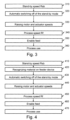
- Fig. 3 shows a flow chart of a preferred embodiment of the invention. At the beginning 310 the crushing plant is driven with stand-by speed Rf.
- the stand-by mode is automatically switched off as certain conditions are fulfilled, when a need to switch off is recognized as described hereinafter.
- the control unit 110 or control system 214 is arranged in such a way that switching of the stand-by mode, i.e. change from stand-by mode to process mode 330,340,350 is carried out automatically.
- step 330 the rotating speed of motor(s) and actuators is raised until the process speed Rf is reached 340.
- the feeding of material into the crushing plant 100 is again enabled at step 350, for example by turning on the actuators participating in the feeding and the operation of the crushing plant 100 continues in process mode.
- Fig. 4 shows a flow chart of a method. At the beginning 410 the crushing plant is driven with stand-by speed Rf.
- material to be processed is recognized on the feeding device, i.e. it is noticed that mineral material is available to be processed.
- the material on the feeding device is recognized with a surface switch, for example an ultrasound sensor, optical sensor, radiation sensor or the like.
- the material on the feeding device is recognized by measuring the pressure, force or tension caused on the feeding device for example with a conveyor scale, strain gauges or the like.
- the material on the feeding device may be recognized from video image or the like with image based measurement.
- a skilled person appreciates that a further common measurement arrangement and/or a combination of several different measurement arrangements may be used to recognize the material on the feeding device.
- the recognition- or measurement information received from the feeding device is relayed to the control unit 110 and/or control system 214 that in response to the received recognition of material on the feeding device starts the switching off of the stand-by mode 430.
- the control unit 110 or control system 214 is arranged in such a way that switching of the stand-by mode, i.e. change from stand-by mode to process mode 440,450,460 is carried out automatically.
- step 440 the rotating speed of motor(s) and actuators is raised until the process speed Rf is reached 450.
- the feeding of material into the crushing plant 100 is again enabled at step 460, for example by turning on the actuators participating in the feeding and the operation of the crushing plant 100 continues in process mode 470.
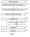
- Fig. 5 shows a flow chart of a preferred embodiment of the invention. At the beginning 510 the crushing plant is driven with stand-by speed Rf.
- step 520 material arriving to be processed is recognized, i.e. it is noticed that mineral material is, if not at once but after a certain time, available to be processed, and so the stand-by mode can be switched off in preparation so that when the material has arrived on the feeding device, the processing can be started without delay.
- the mineral material arriving to be processed is recognized by recognizing the proximity to the feeder device of the mineral material processing plant of a machine or of a part of the machine used to bring the mineral material.
- the machine or apart of the machine to be recognized may for example be an excavator, the scoop of an excavator, a wheel loader or the like.
- nearing of or position of the machine or a part of a machine is, in a preferred embodiment, used for example radio frequency identification (RFID) identifier that has been placed at a suitable position of the machine or a part of the machine.
- RFID radio frequency identification
- a reader or the like is placed on the mineral material processing plant or in proximity thereof and connected to the control unit 110 and/or control system 214. The reader recognizes the proximity to the feeder device of a machine used to bring the material by reading the rfid-identifier.
- GPS global positioning system
- other positioning technology image based measurement from a video image or the like, or a further proximity switch, -sensor, or like measurement is used.
- the material to be processed may be recognized by utilizing information material arriving to be processed available in the control system 214.
- a mineral material processing plant may for example comprise several crushers and/or screens in which case according to a preferred embodiment, measurement information from a previous processing phase is used to recognize material arriving to be processed, for example measurement information that material from pre-crusher is arriving to the next process phase. Further, according to a preferred embodiment, measurement information on material flows of different processing phases of the mineral material processing plant is used to recognize material arriving to be processed.
- material arriving to be processed is recognized by placing identifiers among the material to be processed, for example RFID-identifiers, the proximity of which a reader or the like positioned on the mineral material processing plant or in proximity thereof recognizes.
- identifiers for example RFID-identifiers, the proximity of which a reader or the like positioned on the mineral material processing plant or in proximity thereof recognizes.
- the recognition- or measurement information received is relayed to the control unit 110 and/or control system 214 that in response to the received recognition of material arriving to be processed starts the switching off of the stand-by mode 530.
- the control unit 110 or control system 214 is arranged in such a way that switching of the stand-by mode, i.e. change from stand-by mode to process mode 540-580 is carried out automatically.
- step 540 the rotating speed of motor(s) and actuators is raised until the process speed Rf is reached 550.
- the feeding of material into the crushing plant 100 is again enabled at step 570, for example by turning on the actuators participating in the feeding.
- the material on the feeding device is recognized as hereinbefore described, so that feeding is not enabled before the previously recognized material arriving to be processed is on the feeding device.
- step 580 the operation of the crushing plant 100 continues in process mode.
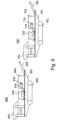
- Fig. 6 shows a mineral material processing plant according to a preferred embodiment of the invention which mineral material processing plant in way of an example comprises two crushing plants 600,700.
- the mineral material processing plant may also comprise more crushing plants and/or screens in different compositions and combinations.
- the crushing plants 600,700 comprise a frame 601,701, a track base 602,702, a feeder 603,703 and a crusher 620,720, such as a cone-, jaw, or gyratory crusher unit.
- the crushing plants 600,700 further comprise a motor unit 604,704 for driving the crusher 620,720 and a conveyor 605,606 for conveying the crushed material for example to the next crusher, screen or to a pile.
- the crushing plants 600,700 may be used for example as intermediate or post processing crusher or in fine crushing.
- the crushing plants 600,700 may be movable also with other means, such as wheels, skids or legs.
- the crushing plants 600,700 may also be fixed.
- the feeder or feeder device 603,703 may be of type of vibration feeder or a belt- or a lamella conveyor.
- the mineral material processing plant and/or one or more crushing plant 600,700 further comprises a hereinbefore described control system 614,714 and a control unit 610,710 with which the mineral material processing plant or one or more crushing plant 610,710 may be automatically driven from a stand-by mode to a process mode as hereinbefore described according to embodiments of the invention.
- the control systems of separate crushing plants 600,700 of the mineral material processing plant are in connection with each other or have been realized as a single system.
- a technical advantage of different embodiments of the invention may be considered to be a decrease of energy consumption and noise production of a mineral material processing plant. Further, a technical advantage of different embodiments of the invention may be considered to be a lengthening of the lifetime of components of a mineral material processing plant. Further, a technical advantage of different embodiments of the invention may be considered to be an increase of environmental friendliness of a mineral material processing plant. Further, a technical advantage of different embodiments of the invention may be considered to be an improvement in the safety and working ergonomics of a mineral material processing plant. Further, a technical advantage of different embodiments of the invention may be considered to be increasing the number of effective usage hours of a mineral material processing plant.
Landscapes
- Engineering & Computer Science (AREA)
- Food Science & Technology (AREA)
- Disintegrating Or Milling (AREA)
- Meat, Egg Or Seafood Products (AREA)
- Crushing And Pulverization Processes (AREA)
- Control Of Conveyors (AREA)
Claims (6)
- Un procédé de commande d'une installation (100) de traitement d'une matière minérale, comprenantle fait de commander le fonctionnement d'actionneurs de l'installation (100) de traitement de matière minérale avec une vitesse de rotation d'un moteur ou de moteurs (104), les actionneurs comprenant un concasseur, un alimentateur et un convoyeur ;le fait de reconnaître automatiquement une nécessité de désactiver un mode veille, dans lequel des actionneurs en mode veille directement en contact avec le traitement de matière minérale de l'installation (100) de traitement de matière minérale continuent de fonctionner à une vitesse de veille réduite, et l'alimentation de la matière dans l'installation (100) de traitement de matière minérale est empêchée en arrêtant l'alimentateur ou le convoyeur d'alimentation ou en choisissant une vitesse de veille de telle manière que l'alimentateur ou le convoyeur d'alimentation ne soit pas à même d'alimenter l'installation de concassage en matière ;en réponse à la nécessité reconnue d'arrêter le mode veille, le fait d'élever la vitesse de fonctionnement du moteur (104) ou des moteurs de l'installation (100) de traitement de matière minérale, depuis une vitesse de veille (Rsb) à une vitesse de traitement (Rf) ; etle fait de permettre l'alimentation de la matière minérale dans l'installation de traitement (100) après que la vitesse de traitement (Rf) soit atteinte ; caractérisé en ce quela nécessité d'arrêter le mode veille est reconnue en reconnaissant le fait que la matière minérale arrive pour être traitée par la reconnaissance de la proximité de l'alimentateur de l'installation de traitement de la matière minérale d'une machine ou d'une partie de la machine utilisée pour amener la matière minérale par la lecture d'un identifiant positionné dans la machine ou dans la partie de la machine.
- Le procédé selon la revendication 1, caractérisé en ce que le fait que la matière minérale arrive pour être traitée est reconnu par la reconnaissance d'un identifiant placé parmi la matière minérale.
- Une installation (100) de traitement de matière minérale, comprenant
des actionneurs, comprenant un concasseur, un alimentateur et un convoyeur :un moteur (104) commandant le fonctionnement d'actionneurs de l'installation (100) de traitement de matière minérale avec sa vitesse de rotation ; etun système de commande (110, 214) ;caractérisée en ce que l'installation de traitement comprend en outreun agencement pour reconnaître une nécessité de désactiver un mode veille ; dans laquelle installation de traitementle système de commande est configuré pour commander l'installation de traitement selon un procédé selon l'une quelconque des revendications 1 à 2 ; et en ce que l'agencement pour reconnaître la nécessité d'arrêter un mode veille comprend un agencement pour reconnaître le fait que la matière arrive pour être traitée comprenant un agencement pour reconnaître la proximité de l'alimentateur de l'installation de traitement de matière minérale d'une machine ou d'une partie de la machine servant à amener la matière minérale qui comprend un agencement de lecture d'un identifiant positionné dans la machine ou dans la partie de la machine. - L'installation de traitement de matière minérale selon la revendication 3, caractérisée en ce que les actionneurs comprennent en outre un tamis.
- L'installation de traitement de matière minérale selon la revendication 3 ou la revendication 4, caractérisée en ce que l'installation de traitement est une parmi ce qui suit : une installation fixe, une installation sur chenilles, une installation sur roues.
- L'installation de traitement de matière minérale selon la revendication 3, caractérisée en ce que l'identifiant positionné dans la machine ou dans la partie de la machine comprend un identifiant d'identification par radiofréquence, RFID.
Applications Claiming Priority (2)
| Application Number | Priority Date | Filing Date | Title |
|---|---|---|---|
| FI20126028A FI129852B (fi) | 2012-10-02 | 2012-10-02 | Menetelmä mineraalimateriaalin prosessointilaitoksen ohjaamiseksi ja mineraalimateriaalin prosessointilaitos |
| PCT/FI2013/050954 WO2014053702A2 (fr) | 2012-10-02 | 2013-10-02 | Procédé de commande d'une installation de traitement d'un matériau minéral et installation de traitement d'un matériau minéral |
Publications (2)
| Publication Number | Publication Date |
|---|---|
| EP2906364A2 EP2906364A2 (fr) | 2015-08-19 |
| EP2906364B1 true EP2906364B1 (fr) | 2023-07-26 |
Family
ID=49641789
Family Applications (1)
| Application Number | Title | Priority Date | Filing Date |
|---|---|---|---|
| EP13795541.5A Active EP2906364B1 (fr) | 2012-10-02 | 2013-10-02 | Procédé de commande d'une installation de traitement d'un matériau minéral et installation de traitement d'un matériau minéral |
Country Status (10)
| Country | Link |
|---|---|
| US (1) | US9993827B2 (fr) |
| EP (1) | EP2906364B1 (fr) |
| JP (1) | JP2015535737A (fr) |
| CN (1) | CN104703716B (fr) |
| AU (1) | AU2013326358B2 (fr) |
| BR (1) | BR112015007286B8 (fr) |
| CA (1) | CA2886508C (fr) |
| FI (1) | FI129852B (fr) |
| RU (1) | RU2651280C2 (fr) |
| WO (1) | WO2014053702A2 (fr) |
Families Citing this family (5)
| Publication number | Priority date | Publication date | Assignee | Title |
|---|---|---|---|---|
| FI128934B (fi) * | 2012-06-08 | 2021-03-31 | Metso Minerals Inc | Menetelmä mineraalimateriaalin prosessointilaitoksen ohjaamiseksi ja mineraalimateriaalin prosessointilaitos |
| US10380529B2 (en) | 2015-08-17 | 2019-08-13 | Caterpillar Paving Products Inc. | Cold planer material transport management system |
| IT201700023354A1 (it) * | 2017-03-02 | 2018-09-02 | Cams Srl | Un metodo di controllo di un impianto di trattamento di elementi da riciclare o smaltire e impianto di trattamento di elementi da riciclare o smaltire |
| EP3456417A1 (fr) * | 2017-09-18 | 2019-03-20 | ABB Schweiz AG | Procédé de fonctionnement d'un circuit de broyage et circuit de broyage respectif |
| CN108580006A (zh) * | 2017-12-27 | 2018-09-28 | 唐山博全实业有限公司 | 一种矿粉生产过程中用的自动上料装置及上料方法 |
Citations (2)
| Publication number | Priority date | Publication date | Assignee | Title |
|---|---|---|---|---|
| JP2000136739A (ja) * | 1998-08-25 | 2000-05-16 | Hitachi Constr Mach Co Ltd | 破砕機のエンジン制御装置 |
| EP2596867A1 (fr) * | 2011-11-28 | 2013-05-29 | Sandvik Intellectual Property AB | Procédé permettant de contrôler un concasseur à cône à inertie |
Family Cites Families (26)
| Publication number | Priority date | Publication date | Assignee | Title |
|---|---|---|---|---|
| JPS6229888A (ja) | 1985-07-30 | 1987-02-07 | 株式会社クボタ | 溶湯スラグ用厚さ検出装置 |
| US4909449A (en) * | 1989-03-10 | 1990-03-20 | Etheridge Johnny E | Primary crushing stage control system |
| JPH0661483B2 (ja) * | 1989-06-09 | 1994-08-17 | 川崎重工業株式会社 | プレス・フィーダ付廃棄物破砕機 |
| US5664113A (en) | 1993-12-10 | 1997-09-02 | Motorola, Inc. | Working asset management system and method |
| JP3449643B2 (ja) * | 1994-07-20 | 2003-09-22 | 株式会社小松製作所 | 自走式破砕機械の破砕機制御装置 |
| US7382274B1 (en) | 2000-01-21 | 2008-06-03 | Agere Systems Inc. | Vehicle interaction communication system |
| FI112829B (fi) | 2000-10-20 | 2004-01-15 | Nokia Corp | Menetelmä kohteen ylläpidon suorittamiseksi ja ylläpitojärjestelmä |
| MXPA03010949A (es) | 2001-05-30 | 2004-03-26 | Gen Electric | Un sistema y metodo para monitorear la condicion de un vehiculo. |
| US6662091B2 (en) | 2001-06-29 | 2003-12-09 | Battelle Memorial Institute | Diagnostics/prognostics using wireless links |
| JP2003170076A (ja) | 2001-12-06 | 2003-06-17 | Hitachi Constr Mach Co Ltd | 自走式破砕機 |
| JP2004188326A (ja) * | 2002-12-11 | 2004-07-08 | Hitachi Constr Mach Co Ltd | 自走式破砕機 |
| JP2004197317A (ja) * | 2002-12-16 | 2004-07-15 | Komatsu Ltd | 土質改良機 |
| JP2004202376A (ja) * | 2002-12-25 | 2004-07-22 | Komatsu Ltd | 破砕装置 |
| JP2004261758A (ja) * | 2003-03-04 | 2004-09-24 | Hitachi Constr Mach Co Ltd | 自走式破砕機の原動機制御装置 |
| JP2005205365A (ja) * | 2004-01-26 | 2005-08-04 | Shin Caterpillar Mitsubishi Ltd | 破砕機の制御装置 |
| US7229041B2 (en) * | 2004-06-30 | 2007-06-12 | Ohio Central Steel Company | Lifting lid crusher |
| US7330117B2 (en) * | 2004-08-25 | 2008-02-12 | Caterpillar Inc. | Systems and methods for radio frequency trigger |
| US7658215B2 (en) * | 2005-07-08 | 2010-02-09 | Rayco Manufacturing, Inc. | Method of operating a wood chipper and power transmission system for use therewith |
| CN2907896Y (zh) * | 2005-12-02 | 2007-06-06 | 上海震旦办公设备有限公司 | 碎纸机 |
| US9328810B2 (en) * | 2006-08-28 | 2016-05-03 | Richard C. Raney | Variable ratio gearmotor with interactive ratio control |
| RU2337756C1 (ru) * | 2007-01-31 | 2008-11-10 | Константин Евсеевич Белоцерковский | Способ управления технологическими параметрами конусной дробилки |
| JP5378371B2 (ja) * | 2008-05-29 | 2013-12-25 | 株式会社小松製作所 | 自走式破砕機、およびその制御方法 |
| SE532429C2 (sv) * | 2008-05-30 | 2010-01-19 | Sandvik Intellectual Property | Anordning och sätt att begränsa spinning i en gyratorisk kross |
| FI122462B (fi) | 2008-06-27 | 2012-01-31 | Metso Minerals Inc | Menetelmä ja laitteisto murskausprosessin säätöön |
| JP2011050949A (ja) * | 2009-08-04 | 2011-03-17 | Nippon Steel Engineering Co Ltd | ごみの収集および選別方法、収集および選別装置 |
| CN102430475A (zh) * | 2011-08-31 | 2012-05-02 | 成都西力投资有限公司 | 矿山轨道式矿选设备及其选矿方法 |
-
2012
- 2012-10-02 FI FI20126028A patent/FI129852B/fi active IP Right Grant
-
2013
- 2013-10-02 WO PCT/FI2013/050954 patent/WO2014053702A2/fr active Application Filing
- 2013-10-02 JP JP2015533654A patent/JP2015535737A/ja active Pending
- 2013-10-02 AU AU2013326358A patent/AU2013326358B2/en active Active
- 2013-10-02 US US14/431,493 patent/US9993827B2/en active Active
- 2013-10-02 BR BR112015007286A patent/BR112015007286B8/pt active IP Right Grant
- 2013-10-02 RU RU2015112927A patent/RU2651280C2/ru active
- 2013-10-02 CN CN201380051675.2A patent/CN104703716B/zh active Active
- 2013-10-02 EP EP13795541.5A patent/EP2906364B1/fr active Active
- 2013-10-02 CA CA2886508A patent/CA2886508C/fr active Active
Patent Citations (2)
| Publication number | Priority date | Publication date | Assignee | Title |
|---|---|---|---|---|
| JP2000136739A (ja) * | 1998-08-25 | 2000-05-16 | Hitachi Constr Mach Co Ltd | 破砕機のエンジン制御装置 |
| EP2596867A1 (fr) * | 2011-11-28 | 2013-05-29 | Sandvik Intellectual Property AB | Procédé permettant de contrôler un concasseur à cône à inertie |
Also Published As
| Publication number | Publication date |
|---|---|
| FI129852B (fi) | 2022-09-30 |
| JP2015535737A (ja) | 2015-12-17 |
| US20150273480A1 (en) | 2015-10-01 |
| EP2906364A2 (fr) | 2015-08-19 |
| BR112015007286A2 (pt) | 2017-07-04 |
| WO2014053702A3 (fr) | 2015-01-08 |
| BR112015007286B1 (pt) | 2020-11-10 |
| CN104703716A (zh) | 2015-06-10 |
| RU2651280C2 (ru) | 2018-04-19 |
| BR112015007286B8 (pt) | 2023-04-18 |
| US9993827B2 (en) | 2018-06-12 |
| CA2886508A1 (fr) | 2014-04-10 |
| AU2013326358B2 (en) | 2018-02-15 |
| AU2013326358A1 (en) | 2015-04-02 |
| CA2886508C (fr) | 2021-05-18 |
| RU2015112927A (ru) | 2016-11-27 |
| WO2014053702A2 (fr) | 2014-04-10 |
| FI20126028A (fi) | 2014-04-03 |
| CN104703716B (zh) | 2019-01-15 |
Similar Documents
| Publication | Publication Date | Title |
|---|---|---|
| EP2906364B1 (fr) | Procédé de commande d'une installation de traitement d'un matériau minéral et installation de traitement d'un matériau minéral | |
| EP2858761B1 (fr) | Procédé pour commander une installation de traitement de matériau minéral et installation de traitement de matériau minéral | |
| EP2836303B1 (fr) | Système et procédé permettant de surveiller et de commander un broyeur, broyeur et procédé permettant de régler un broyeur | |
| CN202490663U (zh) | 横轴冲击式破碎机 | |
| US10335800B2 (en) | Method for controlling a mineral material processing plant and a mineral material processing plant | |
| JP2000136739A5 (fr) | ||
| CN101270565A (zh) | 路面铣刨机排料速度自动控制装置 | |
| CN102847722A (zh) | 型钢废料碎断自动卸料控制方法 | |
| CN202369097U (zh) | 转载机红外线传感器实现人机闭锁功能装置 | |
| CN211436397U (zh) | 一种可实现自动调节的反击板装置 | |
| CN103224130A (zh) | 皮带输送系统流程自动切换方法 | |
| CN203091285U (zh) | 位移式除大块机 | |
| CN203459113U (zh) | 一种有关水平给料滚轴的冲击式破碎机 | |
| CN105173547A (zh) | 一种具有大块煤预破碎功能的过渡槽及刮板输送机 | |
| CN202655334U (zh) | 连轧生产线废料碎断自动卸料装置 | |
| CN201363163Y (zh) | 煤矿综采工作面闭锁系统 |
Legal Events
| Date | Code | Title | Description |
|---|---|---|---|
| PUAI | Public reference made under article 153(3) epc to a published international application that has entered the european phase |
Free format text: ORIGINAL CODE: 0009012 |
|
| 17P | Request for examination filed |
Effective date: 20150311 |
|
| AK | Designated contracting states |
Kind code of ref document: A2 Designated state(s): AL AT BE BG CH CY CZ DE DK EE ES FI FR GB GR HR HU IE IS IT LI LT LU LV MC MK MT NL NO PL PT RO RS SE SI SK SM TR |
|
| AX | Request for extension of the european patent |
Extension state: BA ME |
|
| D17P | Request for examination filed (deleted) | ||
| DAX | Request for extension of the european patent (deleted) | ||
| R17P | Request for examination filed (corrected) |
Effective date: 20150311 |
|
| RAP1 | Party data changed (applicant data changed or rights of an application transferred) |
Owner name: METSO MINERALS, INC. |
|
| STAA | Information on the status of an ep patent application or granted ep patent |
Free format text: STATUS: EXAMINATION IS IN PROGRESS |
|
| RAP1 | Party data changed (applicant data changed or rights of an application transferred) |
Owner name: METSO MINERALS, INC. |
|
| 17Q | First examination report despatched |
Effective date: 20190603 |
|
| STAA | Information on the status of an ep patent application or granted ep patent |
Free format text: STATUS: EXAMINATION IS IN PROGRESS |
|
| RAP3 | Party data changed (applicant data changed or rights of an application transferred) |
Owner name: METSO OUTOTEC FINLAND OY |
|
| STAA | Information on the status of an ep patent application or granted ep patent |
Free format text: STATUS: EXAMINATION IS IN PROGRESS |
|
| REG | Reference to a national code |
Ref country code: DE Ref legal event code: R079 Ref document number: 602013084322 Country of ref document: DE Free format text: PREVIOUS MAIN CLASS: B07B0001420000 Ipc: B02C0025000000 Ref country code: DE Ref legal event code: R079 Free format text: PREVIOUS MAIN CLASS: B07B0001420000 Ipc: B02C0025000000 |
|
| GRAP | Despatch of communication of intention to grant a patent |
Free format text: ORIGINAL CODE: EPIDOSNIGR1 |
|
| STAA | Information on the status of an ep patent application or granted ep patent |
Free format text: STATUS: GRANT OF PATENT IS INTENDED |
|
| RIC1 | Information provided on ipc code assigned before grant |
Ipc: B07B 13/18 20060101ALI20230206BHEP Ipc: B02C 25/00 20060101AFI20230206BHEP |
|
| INTG | Intention to grant announced |
Effective date: 20230224 |
|
| GRAS | Grant fee paid |
Free format text: ORIGINAL CODE: EPIDOSNIGR3 |
|
| GRAA | (expected) grant |
Free format text: ORIGINAL CODE: 0009210 |
|
| STAA | Information on the status of an ep patent application or granted ep patent |
Free format text: STATUS: THE PATENT HAS BEEN GRANTED |
|
| AK | Designated contracting states |
Kind code of ref document: B1 Designated state(s): AL AT BE BG CH CY CZ DE DK EE ES FI FR GB GR HR HU IE IS IT LI LT LU LV MC MK MT NL NO PL PT RO RS SE SI SK SM TR |
|
| P01 | Opt-out of the competence of the unified patent court (upc) registered |
Effective date: 20230621 |
|
| REG | Reference to a national code |
Ref country code: CH Ref legal event code: EP |
|
| REG | Reference to a national code |
Ref country code: DE Ref legal event code: R096 Ref document number: 602013084322 Country of ref document: DE |
|
| REG | Reference to a national code |
Ref country code: IE Ref legal event code: FG4D |
|
| REG | Reference to a national code |
Ref country code: LT Ref legal event code: MG9D |
|
| REG | Reference to a national code |
Ref country code: NL Ref legal event code: MP Effective date: 20230726 |
|
| REG | Reference to a national code |
Ref country code: AT Ref legal event code: MK05 Ref document number: 1591318 Country of ref document: AT Kind code of ref document: T Effective date: 20230726 |
|
| PG25 | Lapsed in a contracting state [announced via postgrant information from national office to epo] |
Ref country code: NL Free format text: LAPSE BECAUSE OF FAILURE TO SUBMIT A TRANSLATION OF THE DESCRIPTION OR TO PAY THE FEE WITHIN THE PRESCRIBED TIME-LIMIT Effective date: 20230726 |
|
| PG25 | Lapsed in a contracting state [announced via postgrant information from national office to epo] |
Ref country code: GR Free format text: LAPSE BECAUSE OF FAILURE TO SUBMIT A TRANSLATION OF THE DESCRIPTION OR TO PAY THE FEE WITHIN THE PRESCRIBED TIME-LIMIT Effective date: 20231027 |
|
| PGFP | Annual fee paid to national office [announced via postgrant information from national office to epo] |
Ref country code: GB Payment date: 20231109 Year of fee payment: 11 |
|
| PG25 | Lapsed in a contracting state [announced via postgrant information from national office to epo] |
Ref country code: IS Free format text: LAPSE BECAUSE OF FAILURE TO SUBMIT A TRANSLATION OF THE DESCRIPTION OR TO PAY THE FEE WITHIN THE PRESCRIBED TIME-LIMIT Effective date: 20231126 |
|
| PG25 | Lapsed in a contracting state [announced via postgrant information from national office to epo] |
Ref country code: SE Free format text: LAPSE BECAUSE OF FAILURE TO SUBMIT A TRANSLATION OF THE DESCRIPTION OR TO PAY THE FEE WITHIN THE PRESCRIBED TIME-LIMIT Effective date: 20230726 Ref country code: RS Free format text: LAPSE BECAUSE OF FAILURE TO SUBMIT A TRANSLATION OF THE DESCRIPTION OR TO PAY THE FEE WITHIN THE PRESCRIBED TIME-LIMIT Effective date: 20230726 Ref country code: PT Free format text: LAPSE BECAUSE OF FAILURE TO SUBMIT A TRANSLATION OF THE DESCRIPTION OR TO PAY THE FEE WITHIN THE PRESCRIBED TIME-LIMIT Effective date: 20231127 Ref country code: NO Free format text: LAPSE BECAUSE OF FAILURE TO SUBMIT A TRANSLATION OF THE DESCRIPTION OR TO PAY THE FEE WITHIN THE PRESCRIBED TIME-LIMIT Effective date: 20231026 Ref country code: LV Free format text: LAPSE BECAUSE OF FAILURE TO SUBMIT A TRANSLATION OF THE DESCRIPTION OR TO PAY THE FEE WITHIN THE PRESCRIBED TIME-LIMIT Effective date: 20230726 Ref country code: LT Free format text: LAPSE BECAUSE OF FAILURE TO SUBMIT A TRANSLATION OF THE DESCRIPTION OR TO PAY THE FEE WITHIN THE PRESCRIBED TIME-LIMIT Effective date: 20230726 Ref country code: IS Free format text: LAPSE BECAUSE OF FAILURE TO SUBMIT A TRANSLATION OF THE DESCRIPTION OR TO PAY THE FEE WITHIN THE PRESCRIBED TIME-LIMIT Effective date: 20231126 Ref country code: HR Free format text: LAPSE BECAUSE OF FAILURE TO SUBMIT A TRANSLATION OF THE DESCRIPTION OR TO PAY THE FEE WITHIN THE PRESCRIBED TIME-LIMIT Effective date: 20230726 Ref country code: GR Free format text: LAPSE BECAUSE OF FAILURE TO SUBMIT A TRANSLATION OF THE DESCRIPTION OR TO PAY THE FEE WITHIN THE PRESCRIBED TIME-LIMIT Effective date: 20231027 Ref country code: FI Free format text: LAPSE BECAUSE OF FAILURE TO SUBMIT A TRANSLATION OF THE DESCRIPTION OR TO PAY THE FEE WITHIN THE PRESCRIBED TIME-LIMIT Effective date: 20230726 Ref country code: AT Free format text: LAPSE BECAUSE OF FAILURE TO SUBMIT A TRANSLATION OF THE DESCRIPTION OR TO PAY THE FEE WITHIN THE PRESCRIBED TIME-LIMIT Effective date: 20230726 |
|
| PGFP | Annual fee paid to national office [announced via postgrant information from national office to epo] |
Ref country code: FR Payment date: 20231116 Year of fee payment: 11 Ref country code: DE Payment date: 20231107 Year of fee payment: 11 |
|
| PG25 | Lapsed in a contracting state [announced via postgrant information from national office to epo] |
Ref country code: PL Free format text: LAPSE BECAUSE OF FAILURE TO SUBMIT A TRANSLATION OF THE DESCRIPTION OR TO PAY THE FEE WITHIN THE PRESCRIBED TIME-LIMIT Effective date: 20230726 |
|
| PG25 | Lapsed in a contracting state [announced via postgrant information from national office to epo] |
Ref country code: ES Free format text: LAPSE BECAUSE OF FAILURE TO SUBMIT A TRANSLATION OF THE DESCRIPTION OR TO PAY THE FEE WITHIN THE PRESCRIBED TIME-LIMIT Effective date: 20230726 |
|
| PG25 | Lapsed in a contracting state [announced via postgrant information from national office to epo] |
Ref country code: SM Free format text: LAPSE BECAUSE OF FAILURE TO SUBMIT A TRANSLATION OF THE DESCRIPTION OR TO PAY THE FEE WITHIN THE PRESCRIBED TIME-LIMIT Effective date: 20230726 Ref country code: RO Free format text: LAPSE BECAUSE OF FAILURE TO SUBMIT A TRANSLATION OF THE DESCRIPTION OR TO PAY THE FEE WITHIN THE PRESCRIBED TIME-LIMIT Effective date: 20230726 Ref country code: ES Free format text: LAPSE BECAUSE OF FAILURE TO SUBMIT A TRANSLATION OF THE DESCRIPTION OR TO PAY THE FEE WITHIN THE PRESCRIBED TIME-LIMIT Effective date: 20230726 Ref country code: EE Free format text: LAPSE BECAUSE OF FAILURE TO SUBMIT A TRANSLATION OF THE DESCRIPTION OR TO PAY THE FEE WITHIN THE PRESCRIBED TIME-LIMIT Effective date: 20230726 Ref country code: DK Free format text: LAPSE BECAUSE OF FAILURE TO SUBMIT A TRANSLATION OF THE DESCRIPTION OR TO PAY THE FEE WITHIN THE PRESCRIBED TIME-LIMIT Effective date: 20230726 Ref country code: CZ Free format text: LAPSE BECAUSE OF FAILURE TO SUBMIT A TRANSLATION OF THE DESCRIPTION OR TO PAY THE FEE WITHIN THE PRESCRIBED TIME-LIMIT Effective date: 20230726 Ref country code: SK Free format text: LAPSE BECAUSE OF FAILURE TO SUBMIT A TRANSLATION OF THE DESCRIPTION OR TO PAY THE FEE WITHIN THE PRESCRIBED TIME-LIMIT Effective date: 20230726 |