EP2905646A1 - Microscope - Google Patents
Microscope Download PDFInfo
- Publication number
- EP2905646A1 EP2905646A1 EP15152836.1A EP15152836A EP2905646A1 EP 2905646 A1 EP2905646 A1 EP 2905646A1 EP 15152836 A EP15152836 A EP 15152836A EP 2905646 A1 EP2905646 A1 EP 2905646A1
- Authority
- EP
- European Patent Office
- Prior art keywords
- immersion
- immersion medium
- objective lens
- supply
- mounting part
- Prior art date
- Legal status (The legal status is an assumption and is not a legal conclusion. Google has not performed a legal analysis and makes no representation as to the accuracy of the status listed.)
- Withdrawn
Links
- 238000007654 immersion Methods 0.000 claims abstract description 125
- 239000002609 medium Substances 0.000 description 74
- 239000007788 liquid Substances 0.000 description 10
- 239000006059 cover glass Substances 0.000 description 7
- 238000010586 diagram Methods 0.000 description 3
- 239000000428 dust Substances 0.000 description 3
- 239000002699 waste material Substances 0.000 description 3
- XLYOFNOQVPJJNP-UHFFFAOYSA-N water Substances O XLYOFNOQVPJJNP-UHFFFAOYSA-N 0.000 description 3
- 230000000694 effects Effects 0.000 description 2
- 230000003287 optical effect Effects 0.000 description 2
- 229920003023 plastic Polymers 0.000 description 2
- 238000007599 discharging Methods 0.000 description 1
- 239000001963 growth medium Substances 0.000 description 1
- 238000005286 illumination Methods 0.000 description 1
- 230000002572 peristaltic effect Effects 0.000 description 1
- 229920001296 polysiloxane Polymers 0.000 description 1
Images


Classifications
-
- G—PHYSICS
- G02—OPTICS
- G02B—OPTICAL ELEMENTS, SYSTEMS OR APPARATUS
- G02B21/00—Microscopes
- G02B21/33—Immersion oils, or microscope systems or objectives for use with immersion fluids
Definitions
- the present invention relates to a microscope.
- Patent Literature 1 there is known a microscope in which a cover glass on which a specimen is loaded is mounted on a stage, and an immersion medium is supplied to a gap between an objective lens that comes close the cover glass from below and the cover glass (refer to Patent Literature 1, for example).
- the microscope is provided with a saucer in a periphery of the objective lens. If an immersion medium supplied from a water supply nozzle is spilled from the gap between the objective lens and the cover glass, the immersion medium flowing to the periphery of the objective lens is received by the saucer and discharged.
- a specimen tray (a dish of ⁇ 35 mm, or a microplate) using a film-like mounting part composed of a transparent thin plastic or the like has been used instead of a cover glass.
- a film-like mounting part composed of a transparent thin plastic or the like.
- the present invention is made in light of the above-mentioned circumstances, and it is an object to provide a microscope that is capable of precisely controlling the amount of an immersion medium held in a gap between an objective lens and a mounting part, and of observing a specimen without varying the mounting part.
- One aspect of the present invention is a microscope that includes a supply port from which an immersion medium is supplied to a gap between a film-like mounting part on which a specimen is loaded and an immersion objective lens, and a suction port that is arranged so as to be able to be brought into contact with the immersion medium supplied from the supply port, and from which the immersion medium can be sucked.
- the present aspect it is possible to force the immersion medium supplied to the gap between the film-like mounting part and the immersion objective lens from the supply port to be discharged from the gap between the mounting part and the immersion objective lens after the immersion medium is sucked through the suction port.
- supply means that is connected to the supply port and that supplies an immersion medium to the gap between the mounting part and the immersion objective lens through the supply port, and suction means that is connected to the suction port and that sucks the immersion medium through the suction port.
- the immersion medium is supplied to the gap between the mounting part and the immersion objective lens through the supply port by operation of the supply means, and the immersion medium is sucked by operation of the suction means.
- control unit that controls the supply means and the suction means to be simultaneously driven so that the immersion medium flows.
- control unit may control the supply means and the suction means so that the immersion medium held in the gap between the mounting part and the immersion objective lens increases by a predetermined amount per unit of time.
- control unit controls the supply means and the suction means to supply the immersion medium so that the immersion medium increases by a predetermined amount per unit of time after the immersion medium is completely removed from the gap between the mounting part and the immersion objective lens temporarily.
- the control unit controls the supply means and the suction means to supply the immersion medium so that the immersion medium increases by a predetermined amount per unit of time after the immersion medium is completely removed from the gap between the mounting part and the immersion objective lens temporarily.
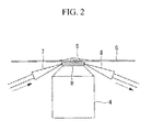
- the microscope 1 in accordance with the present embodiment is provided with a case 2 in which temperature and humidity are controlled, and the microscope 1 includes the following in the case: a stage 3 on which a specimen S is loaded; a microscope body 5 provided with an immersion objective lens 4 that is arranged upward so as to be close to a lower side of the stage 3; and a medium supply-discharge device 6 for supplying an immersion medium B such as pure water to the gap between the immersion objective lens 4 and the specimen S and for discharging the immersion medium B therefrom.
- an immersion medium B such as pure water
- the specimen S is mounted on the stage 3 in a state where the specimen S is loaded on a mounting part G composed of a film-like transparent plastic.
- the stage 3 is provided with an opening 3a through which the specimen S is irradiated from below over the immersion medium B and the mounting part G on the stage 3 with illumination light from the microscope body 5 condensed by the immersion objective lens 4.
- the immersion objective lens 4 is composed a combination of a large number of lenses (not shown).
- the immersion medium B is injected into a gap between a top face 4a of the top of the immersion objective lens 4 and the mounting part G, the immersion medium B is held in the gap by surface tension.
- the medium supply-discharge device 6 includes a supply nozzle (supply port) 7 and a suction nozzle (suction port) 8 whose tips are arranged in the gap between the mounting part G and the immersion objective lens 4.
- a supply nozzle 7 and the suction nozzle 8 is provided at its tip with an opening through which the immersion medium B is supplied or sucked.
- the tips of the supply nozzle 7 and the suction nozzle 8 are arranged at positions 180° apart around an optical axis of the immersion objective lens 4 to face each other.
- a liquid supply container 10 is connected to a base end of the supply nozzle 7 through a pipe 9 in the middle of which a supply pump (supply means) 11 is arranged to feed the immersion medium B contained in the liquid supply container 10.
- a waste liquid container 13 is connected to a base end of the suction nozzle 8 through a pipe 12 in the middle of which a suction pump (suction means) 14 is arranged to feed the immersion medium B to the waste liquid container 13.
- the medium supply-discharge device 6 is operated to supply the immersion medium B into the gap between the mounting part G and the immersion objective lens 4.
- the supply pump 11 of the medium supply-discharge device 6 is operated to enable the immersion medium B contained in the liquid supply container 10 to be supplied to the gap between the mounting part G and the immersion objective lens 4 through the pipe 9 and the supply nozzle 7 at a predetermined flow rate per unit of time.
- the supply pump 11 of the medium supply-discharge device 6 is operated to enable the immersion medium B contained in the liquid supply container 10 to be supplied to the gap between the mounting part G and the immersion objective lens 4 through the pipe 9 and the supply nozzle 7 at a predetermined flow rate per unit of time.
- the medium supply-discharge device 6 includes the suction pump 14 and the suction nozzle 8.
- control unit 15 to be connected to the supply pump 11 and the suction pump 14 so that the control unit 15 may control the supply pump 11 and the suction pump 12.
- control unit 15 first allows the supply pump 11 to operate to supply the predetermined amount of the immersion medium B into the gap between the mounting part G and the immersion objective lens 4, and next allows the supply pump 11 and the suction pump 14 to simultaneously operate so that the suction pump 14 may operate to suck the immersion medium B, which is supplied into the gap between the mounting part G and the immersion objective lens 4 by the supply pump 11 through the supply nozzle 7, from the gap between the mounting part G and the immersion objective lens 4 through the suction nozzle 8.
- the immersion medium B It is possible to allow the immersion medium B to flow in one direction in the gap between the mounting part G and the immersion objective lens 4 without varying the amount the immersion medium B supplied first by allowing the amount of supply by the supply pump 11 to equal the amount of suction by the suction pump 14.
- flowing of the immersion medium B washes the bubbles, dust, and the like away so that it is possible to easily remove the bubbles, dust, and the like from the gap between the mounting part G and the immersion objective lens 4.
- the immersion medium B is a liquid with high viscosity such as silicone
- only supplying the immersion medium B allows formed bubbles to sometimes remain because the bubbles are enclosed by the immersion medium, however, allowing the immersion medium B to flow enables such inconvenience to be prevented from occurring.
- the control unit 15 may be configured to allow the supply pump 11 and the suction pump 14 to simultaneously operate by providing a certain difference between the amount of supply by the supply pump 11 and the amount of suction by the suction pump 14 so that the immersion medium B provided into the gap between the mounting part G and the immersion objective lens 4 sequentially increases by a certain amount per unit of time.
- control unit 15 can precisely control the amount of the immersion medium B by only controlling operation time of the supply pump 11 and the suction pump 14.
- a cylindrical gap 16a is formed between a cylindrical cap 16 with which a case 4b of the immersion objective lens 4 is covered and an outer face of the case 4b of the immersion objective lens 4 so that the immersion medium B may be supplied and sucked from an opening provided all around the outside in a radial direction of the top face 4a of the immersion objective lens 4 through the gap. In this manner, it is possible to reliably supply the immersion medium B to the immersion objective lens 4 and suck the immersion medium B therefrom.
- two or more respective supply nozzles 7 and suction nozzles 8 may be provided, and the nozzles may be arranged in a position relation other than 180°.
- the supply pump 11 connected to the supply nozzle 7 and the suction pump 14 connected to the suction nozzle 8 are provided separately, instead of the pumps, a shared pump may be used for both of the pumps. In this case, a peristaltic pump is available.
- a shared liquid supply container 10 may be used for both of the containers.
- a filter is shown in Fig. 5 with a reference numeral 17, so that the immersion medium B sucked should be returned to the liquid supply container 10 after filtered by the filter 17.
Landscapes
- Chemical & Material Sciences (AREA)
- Physics & Mathematics (AREA)
- Oil, Petroleum & Natural Gas (AREA)
- Analytical Chemistry (AREA)
- General Physics & Mathematics (AREA)
- Optics & Photonics (AREA)
- Microscoopes, Condenser (AREA)
Applications Claiming Priority (1)
| Application Number | Priority Date | Filing Date | Title |
|---|---|---|---|
| JP2014015828A JP6261357B2 (ja) | 2014-01-30 | 2014-01-30 | 顕微鏡および観察方法 |
Publications (1)
| Publication Number | Publication Date |
|---|---|
| EP2905646A1 true EP2905646A1 (en) | 2015-08-12 |
Family
ID=52396589
Family Applications (1)
| Application Number | Title | Priority Date | Filing Date |
|---|---|---|---|
| EP15152836.1A Withdrawn EP2905646A1 (en) | 2014-01-30 | 2015-01-28 | Microscope |
Country Status (3)
| Country | Link |
|---|---|
| US (1) | US9606347B2 (ja) |
| EP (1) | EP2905646A1 (ja) |
| JP (1) | JP6261357B2 (ja) |
Cited By (3)
| Publication number | Priority date | Publication date | Assignee | Title |
|---|---|---|---|---|
| DE102018126526A1 (de) | 2018-10-24 | 2020-04-30 | Carl Zeiss Microscopy Gmbh | Immersionsmittelaufbringung mittels einer Strahldüse |
| DE102018126527A1 (de) | 2018-10-24 | 2020-04-30 | Carl Zeiss Microscopy Gmbh | Vorrichtung und Verfahren zum Aufbringen eines flüssigen Immersionsmittels in einen Spalt zwischen einem Mikroskopobjektiv und einer zu mikroskopierenden Probe |
| US12099176B2 (en) | 2018-10-24 | 2024-09-24 | Carl Zeiss Microscopy Gmbh | Apparatus and method for applying a liquid immersion medium into a clearance between a microscope objective and a specimen to be examined under the microscope |
Families Citing this family (16)
| Publication number | Priority date | Publication date | Assignee | Title |
|---|---|---|---|---|
| JP6399037B2 (ja) * | 2016-05-18 | 2018-10-03 | 横河電機株式会社 | 対物レンズユニット及び液浸顕微鏡 |
| JP6904414B2 (ja) | 2017-03-31 | 2021-07-14 | 株式会社ニコン | 液体供給装置、対物レンズ保持装置、顕微鏡、及び液体供給方法 |
| US10267790B1 (en) | 2017-11-17 | 2019-04-23 | Ultima Genomics, Inc. | Systems for biological sample processing and analysis |
| US11499962B2 (en) | 2017-11-17 | 2022-11-15 | Ultima Genomics, Inc. | Methods and systems for analyte detection and analysis |
| JP2019128371A (ja) * | 2018-01-22 | 2019-08-01 | オリンパス株式会社 | 倒立型顕微鏡および標本観察方法 |
| JP6525296B2 (ja) * | 2018-07-04 | 2019-06-05 | 横河電機株式会社 | 対物レンズユニット |
| FR3086067A1 (fr) | 2018-09-18 | 2020-03-20 | Centre National De La Recherche Scientifique | Accessoire amovible de collecte d'un surplus de liquide d'immersion pour un objectif a immersion inverse. |
| US10512911B1 (en) | 2018-12-07 | 2019-12-24 | Ultima Genomics, Inc. | Implementing barriers for controlled environments during sample processing and detection |
| US11118223B2 (en) | 2019-03-14 | 2021-09-14 | Ultima Genomics, Inc. | Methods, devices, and systems for analyte detection and analysis |
| US10900078B2 (en) | 2019-03-14 | 2021-01-26 | Ultima Genomics, Inc. | Methods, devices, and systems for analyte detection and analysis |
| US10830703B1 (en) | 2019-03-14 | 2020-11-10 | Ultima Genomics, Inc. | Methods, devices, and systems for analyte detection and analysis |
| US10852518B1 (en) * | 2019-03-14 | 2020-12-01 | Ultima Genomics, Inc. | Methods, devices, and systems for analyte detection and analysis |
| DE102019115780B4 (de) * | 2019-06-11 | 2021-10-21 | Technische Universität Dresden | Verfahren und Vorrichtungen zum Mehrphotonendruck und zur Inspektion dreidimensionaler Strukturen |
| DE102020111715A1 (de) * | 2020-04-29 | 2021-11-04 | Carl Zeiss Microscopy Gmbh | Immersionsobjektiv und verfahren zur immersionsmikroskopie |
| CN114002839B (zh) * | 2021-09-29 | 2024-06-25 | 深圳高性能医疗器械国家研究院有限公司 | 一种可倒置使用的浸液物镜及具有该浸液物镜的显微镜 |
| WO2024098243A1 (zh) * | 2022-11-08 | 2024-05-16 | 深圳华大智造科技股份有限公司 | 给排液装置及方法、浸没物镜系统、基因测序仪和生化检测方法 |
Citations (4)
| Publication number | Priority date | Publication date | Assignee | Title |
|---|---|---|---|---|
| JP2004070307A (ja) | 2002-06-11 | 2004-03-04 | Olympus Corp | 液浸媒質供給装置、蛍光分光検査装置及び培養顕微鏡 |
| WO2005010591A1 (de) * | 2003-07-23 | 2005-02-03 | Evotec Technologies Gmbh | Vorrichtung und verfahren zur untersuchung chemischer und/ oder biologischer proben sowie objektivaufsatz |
| JP2005234457A (ja) * | 2004-02-23 | 2005-09-02 | Nikon Corp | 顕微鏡観察装置 |
| EP1855140A1 (en) * | 2005-02-28 | 2007-11-14 | Nikon Corporation | Microscope-use adaptor and microscope device |
Family Cites Families (15)
| Publication number | Priority date | Publication date | Assignee | Title |
|---|---|---|---|---|
| WO2005031823A1 (ja) * | 2003-09-29 | 2005-04-07 | Nikon Corporation | 液浸型レンズ系及び投影露光装置、並びにデバイス製造方法 |
| DE102004033195A1 (de) * | 2004-07-09 | 2006-02-23 | Leica Microsystems Semiconductor Gmbh | Vorrichtung zur Inspektion eines mikroskopischen Bauteils |
| JP4451446B2 (ja) * | 2004-07-22 | 2010-04-14 | オリンパス株式会社 | 温度調節機構を有する観察装置 |
| US7936441B2 (en) * | 2005-05-12 | 2011-05-03 | Nikon Corporation | Projection optical system, exposure apparatus, and exposure method |
| JP4735186B2 (ja) * | 2005-10-21 | 2011-07-27 | 株式会社ニコン | 液浸顕微鏡装置 |
| US20070127135A1 (en) * | 2005-11-01 | 2007-06-07 | Nikon Corporation | Exposure apparatus, exposure method and device manufacturing method |
| WO2007135762A1 (ja) * | 2006-05-22 | 2007-11-29 | Tokai Hit Co., Ltd. | 液浸用液の供給装置、対物レンズ及び液浸用液の供給制御方法 |
| JP5597868B2 (ja) * | 2006-09-07 | 2014-10-01 | ライカ マイクロシステムズ ツェーエムエス ゲーエムベーハー | 液浸対物レンズ、液浸膜を形成する装置及び方法 |
| JP5021287B2 (ja) * | 2006-12-20 | 2012-09-05 | オリンパス株式会社 | 蛍光撮像方法及び蛍光撮像装置 |
| JP4328359B2 (ja) * | 2007-01-15 | 2009-09-09 | オリンパス株式会社 | 液浸対物レンズを備えた観察装置 |
| JP5047671B2 (ja) * | 2007-04-10 | 2012-10-10 | オリンパス株式会社 | 顕微鏡装置 |
| DE102008027784B4 (de) * | 2008-06-11 | 2021-05-20 | Carl Zeiss Microscopy Gmbh | Verfahren zum Positionieren einer Probe im Detektionsbereich eines Objektivs |
| JP5153568B2 (ja) * | 2008-10-27 | 2013-02-27 | オリンパス株式会社 | 顕微鏡装置 |
| US8947776B2 (en) * | 2010-06-23 | 2015-02-03 | Hamamatsu Photonics K.K. | Suction apparatus, semiconductor device observation device, and semiconductor device observation method |
| JP6037732B2 (ja) * | 2012-09-03 | 2016-12-07 | オリンパス株式会社 | 浸液保持具、観察部位固定装置、及び、顕微鏡 |
-
2014
- 2014-01-30 JP JP2014015828A patent/JP6261357B2/ja active Active
-
2015
- 2015-01-28 EP EP15152836.1A patent/EP2905646A1/en not_active Withdrawn
- 2015-01-29 US US14/608,979 patent/US9606347B2/en active Active
Patent Citations (4)
| Publication number | Priority date | Publication date | Assignee | Title |
|---|---|---|---|---|
| JP2004070307A (ja) | 2002-06-11 | 2004-03-04 | Olympus Corp | 液浸媒質供給装置、蛍光分光検査装置及び培養顕微鏡 |
| WO2005010591A1 (de) * | 2003-07-23 | 2005-02-03 | Evotec Technologies Gmbh | Vorrichtung und verfahren zur untersuchung chemischer und/ oder biologischer proben sowie objektivaufsatz |
| JP2005234457A (ja) * | 2004-02-23 | 2005-09-02 | Nikon Corp | 顕微鏡観察装置 |
| EP1855140A1 (en) * | 2005-02-28 | 2007-11-14 | Nikon Corporation | Microscope-use adaptor and microscope device |
Cited By (6)
| Publication number | Priority date | Publication date | Assignee | Title |
|---|---|---|---|---|
| DE102018126526A1 (de) | 2018-10-24 | 2020-04-30 | Carl Zeiss Microscopy Gmbh | Immersionsmittelaufbringung mittels einer Strahldüse |
| DE102018126527A1 (de) | 2018-10-24 | 2020-04-30 | Carl Zeiss Microscopy Gmbh | Vorrichtung und Verfahren zum Aufbringen eines flüssigen Immersionsmittels in einen Spalt zwischen einem Mikroskopobjektiv und einer zu mikroskopierenden Probe |
| WO2020083747A1 (de) | 2018-10-24 | 2020-04-30 | Carl Zeiss Microscopy Gmbh | Immersionsmittelaufbringung mittels einer strahldüse |
| WO2020083746A1 (de) | 2018-10-24 | 2020-04-30 | Carl Zeiss Microscopy Gmbh | Vorrichtung und verfahren zum aufbringen eines flüssigen immersionsmittels in einen spalt zwischen einem mikroskopobjektiv und einer zu mikroskopierenden probe |
| US12061330B2 (en) | 2018-10-24 | 2024-08-13 | Carl Zeiss Microscopy Gmbh | Immersion medium application by means of an injection nozzle |
| US12099176B2 (en) | 2018-10-24 | 2024-09-24 | Carl Zeiss Microscopy Gmbh | Apparatus and method for applying a liquid immersion medium into a clearance between a microscope objective and a specimen to be examined under the microscope |
Also Published As
| Publication number | Publication date |
|---|---|
| US9606347B2 (en) | 2017-03-28 |
| JP2015141396A (ja) | 2015-08-03 |
| JP6261357B2 (ja) | 2018-01-17 |
| US20150212310A1 (en) | 2015-07-30 |
Similar Documents
| Publication | Publication Date | Title |
|---|---|---|
| EP2905646A1 (en) | Microscope | |
| TWI521209B (zh) | Dispensing device and liquid dispensing device and liquid dispensing method | |
| JP6051493B2 (ja) | 液浸対物レンズ、液浸膜を形成する装置及び方法 | |
| EP3330366B1 (en) | Method and device for moving object | |
| RU2017101085A (ru) | Картридж для быстрого отбора пробы | |
| JP2015018237A (ja) | 浸漬膜形成装置 | |
| CN101952730B (zh) | 清洗装置和自动分析装置 | |
| US9329195B2 (en) | Container cleaning device, discharge member for container cleaning device, and analyzer | |
| US7960183B2 (en) | Biochip manufacturing method and biochip manufacturing device | |
| EP3159397A1 (en) | Head device for mounting dispensing tip thereon, and movement device using same | |
| CN110267746A (zh) | 涂敷装置和气泡去除方法 | |
| US20160288018A1 (en) | Deoxygenation apparatus and substrate processing apparatus | |
| JP6450476B2 (ja) | 対象物移動方法及び装置 | |
| US9563049B2 (en) | Procedure and device for terminating the immersion at a microscope | |
| KR102627121B1 (ko) | 노즐 대기 장치, 액 처리 장치 및 액 처리 장치의 운전 방법 및 기억 매체 | |
| EP2075586A1 (en) | Dispenser | |
| CN109070148B (zh) | 用于分析仪器的探针清洗站 | |
| JP2017161233A (ja) | マイクロチップ電気泳動装置 | |
| JP2010133843A (ja) | サンプル液供給方法及び容器 | |
| US20120236312A1 (en) | Microchip, liquid sample supply device, supply method of liquid sample, and analysis device | |
| EP2803412A2 (en) | Device and Method for Supplying Disposable Tips to a Pipetting System | |
| KR20150106538A (ko) | 디스펜서의 액맺힘 방지 장치 및 그 동작 방법 | |
| JP2010048738A (ja) | 分注装置および分注装置における目詰まり除去方法 | |
| JP2015190946A (ja) | 液体分注装置および液体分注方法 | |
| JP2015190855A (ja) | マイクロチップへの試薬注入量制御装置及び方法 |
Legal Events
| Date | Code | Title | Description |
|---|---|---|---|
| PUAI | Public reference made under article 153(3) epc to a published international application that has entered the european phase |
Free format text: ORIGINAL CODE: 0009012 |
|
| AK | Designated contracting states |
Kind code of ref document: A1 Designated state(s): AL AT BE BG CH CY CZ DE DK EE ES FI FR GB GR HR HU IE IS IT LI LT LU LV MC MK MT NL NO PL PT RO RS SE SI SK SM TR |
|
| AX | Request for extension of the european patent |
Extension state: BA ME |
|
| 17P | Request for examination filed |
Effective date: 20160211 |
|
| RBV | Designated contracting states (corrected) |
Designated state(s): AL AT BE BG CH CY CZ DE DK EE ES FI FR GB GR HR HU IE IS IT LI LT LU LV MC MK MT NL NO PL PT RO RS SE SI SK SM TR |
|
| RAP1 | Party data changed (applicant data changed or rights of an application transferred) |
Owner name: OLYMPUS CORPORATION |
|
| RAP1 | Party data changed (applicant data changed or rights of an application transferred) |
Owner name: OLYMPUS CORPORATION |
|
| RIN1 | Information on inventor provided before grant (corrected) |
Inventor name: FUKUDA, TATSUSHI Inventor name: HEBIISHI, HIROYASU |
|
| STAA | Information on the status of an ep patent application or granted ep patent |
Free format text: STATUS: EXAMINATION IS IN PROGRESS |
|
| 17Q | First examination report despatched |
Effective date: 20190802 |
|
| STAA | Information on the status of an ep patent application or granted ep patent |
Free format text: STATUS: THE APPLICATION IS DEEMED TO BE WITHDRAWN |
|
| 18D | Application deemed to be withdrawn |
Effective date: 20191213 |