EP2905646A1 - Microscope - Google Patents
Microscope Download PDFInfo
- Publication number
- EP2905646A1 EP2905646A1 EP15152836.1A EP15152836A EP2905646A1 EP 2905646 A1 EP2905646 A1 EP 2905646A1 EP 15152836 A EP15152836 A EP 15152836A EP 2905646 A1 EP2905646 A1 EP 2905646A1
- Authority
- EP
- European Patent Office
- Prior art keywords
- immersion
- immersion medium
- objective lens
- supply
- mounting part
- Prior art date
- Legal status (The legal status is an assumption and is not a legal conclusion. Google has not performed a legal analysis and makes no representation as to the accuracy of the status listed.)
- Withdrawn
Links
- 238000007654 immersion Methods 0.000 claims abstract description 125
- 239000002609 medium Substances 0.000 description 74
- 239000007788 liquid Substances 0.000 description 10
- 239000006059 cover glass Substances 0.000 description 7
- 238000010586 diagram Methods 0.000 description 3
- 239000000428 dust Substances 0.000 description 3
- 239000002699 waste material Substances 0.000 description 3
- XLYOFNOQVPJJNP-UHFFFAOYSA-N water Substances O XLYOFNOQVPJJNP-UHFFFAOYSA-N 0.000 description 3
- 230000000694 effects Effects 0.000 description 2
- 230000003287 optical effect Effects 0.000 description 2
- 229920003023 plastic Polymers 0.000 description 2
- 238000007599 discharging Methods 0.000 description 1
- 239000001963 growth medium Substances 0.000 description 1
- 238000005286 illumination Methods 0.000 description 1
- 230000002572 peristaltic effect Effects 0.000 description 1
- 229920001296 polysiloxane Polymers 0.000 description 1
Images


Classifications
-
- G—PHYSICS
- G02—OPTICS
- G02B—OPTICAL ELEMENTS, SYSTEMS OR APPARATUS
- G02B21/00—Microscopes
- G02B21/33—Immersion oils, or microscope systems or objectives for use with immersion fluids
Definitions
- the present invention relates to a microscope.
- Patent Literature 1 there is known a microscope in which a cover glass on which a specimen is loaded is mounted on a stage, and an immersion medium is supplied to a gap between an objective lens that comes close the cover glass from below and the cover glass (refer to Patent Literature 1, for example).
- the microscope is provided with a saucer in a periphery of the objective lens. If an immersion medium supplied from a water supply nozzle is spilled from the gap between the objective lens and the cover glass, the immersion medium flowing to the periphery of the objective lens is received by the saucer and discharged.
- a specimen tray (a dish of ⁇ 35 mm, or a microplate) using a film-like mounting part composed of a transparent thin plastic or the like has been used instead of a cover glass.
- a film-like mounting part composed of a transparent thin plastic or the like.
- the present invention is made in light of the above-mentioned circumstances, and it is an object to provide a microscope that is capable of precisely controlling the amount of an immersion medium held in a gap between an objective lens and a mounting part, and of observing a specimen without varying the mounting part.
- One aspect of the present invention is a microscope that includes a supply port from which an immersion medium is supplied to a gap between a film-like mounting part on which a specimen is loaded and an immersion objective lens, and a suction port that is arranged so as to be able to be brought into contact with the immersion medium supplied from the supply port, and from which the immersion medium can be sucked.
- the present aspect it is possible to force the immersion medium supplied to the gap between the film-like mounting part and the immersion objective lens from the supply port to be discharged from the gap between the mounting part and the immersion objective lens after the immersion medium is sucked through the suction port.
- supply means that is connected to the supply port and that supplies an immersion medium to the gap between the mounting part and the immersion objective lens through the supply port, and suction means that is connected to the suction port and that sucks the immersion medium through the suction port.
- the immersion medium is supplied to the gap between the mounting part and the immersion objective lens through the supply port by operation of the supply means, and the immersion medium is sucked by operation of the suction means.
- control unit that controls the supply means and the suction means to be simultaneously driven so that the immersion medium flows.
- control unit may control the supply means and the suction means so that the immersion medium held in the gap between the mounting part and the immersion objective lens increases by a predetermined amount per unit of time.
- control unit controls the supply means and the suction means to supply the immersion medium so that the immersion medium increases by a predetermined amount per unit of time after the immersion medium is completely removed from the gap between the mounting part and the immersion objective lens temporarily.
- the control unit controls the supply means and the suction means to supply the immersion medium so that the immersion medium increases by a predetermined amount per unit of time after the immersion medium is completely removed from the gap between the mounting part and the immersion objective lens temporarily.
- the microscope 1 in accordance with the present embodiment is provided with a case 2 in which temperature and humidity are controlled, and the microscope 1 includes the following in the case: a stage 3 on which a specimen S is loaded; a microscope body 5 provided with an immersion objective lens 4 that is arranged upward so as to be close to a lower side of the stage 3; and a medium supply-discharge device 6 for supplying an immersion medium B such as pure water to the gap between the immersion objective lens 4 and the specimen S and for discharging the immersion medium B therefrom.
- an immersion medium B such as pure water
- the specimen S is mounted on the stage 3 in a state where the specimen S is loaded on a mounting part G composed of a film-like transparent plastic.
- the stage 3 is provided with an opening 3a through which the specimen S is irradiated from below over the immersion medium B and the mounting part G on the stage 3 with illumination light from the microscope body 5 condensed by the immersion objective lens 4.
- the immersion objective lens 4 is composed a combination of a large number of lenses (not shown).
- the immersion medium B is injected into a gap between a top face 4a of the top of the immersion objective lens 4 and the mounting part G, the immersion medium B is held in the gap by surface tension.
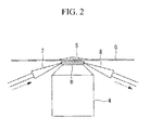
- the medium supply-discharge device 6 includes a supply nozzle (supply port) 7 and a suction nozzle (suction port) 8 whose tips are arranged in the gap between the mounting part G and the immersion objective lens 4.
- a supply nozzle 7 and the suction nozzle 8 is provided at its tip with an opening through which the immersion medium B is supplied or sucked.
- the tips of the supply nozzle 7 and the suction nozzle 8 are arranged at positions 180° apart around an optical axis of the immersion objective lens 4 to face each other.
- a liquid supply container 10 is connected to a base end of the supply nozzle 7 through a pipe 9 in the middle of which a supply pump (supply means) 11 is arranged to feed the immersion medium B contained in the liquid supply container 10.
- a waste liquid container 13 is connected to a base end of the suction nozzle 8 through a pipe 12 in the middle of which a suction pump (suction means) 14 is arranged to feed the immersion medium B to the waste liquid container 13.
- the medium supply-discharge device 6 is operated to supply the immersion medium B into the gap between the mounting part G and the immersion objective lens 4.
- the supply pump 11 of the medium supply-discharge device 6 is operated to enable the immersion medium B contained in the liquid supply container 10 to be supplied to the gap between the mounting part G and the immersion objective lens 4 through the pipe 9 and the supply nozzle 7 at a predetermined flow rate per unit of time.
- the supply pump 11 of the medium supply-discharge device 6 is operated to enable the immersion medium B contained in the liquid supply container 10 to be supplied to the gap between the mounting part G and the immersion objective lens 4 through the pipe 9 and the supply nozzle 7 at a predetermined flow rate per unit of time.
- the medium supply-discharge device 6 includes the suction pump 14 and the suction nozzle 8.
- control unit 15 to be connected to the supply pump 11 and the suction pump 14 so that the control unit 15 may control the supply pump 11 and the suction pump 12.
- control unit 15 first allows the supply pump 11 to operate to supply the predetermined amount of the immersion medium B into the gap between the mounting part G and the immersion objective lens 4, and next allows the supply pump 11 and the suction pump 14 to simultaneously operate so that the suction pump 14 may operate to suck the immersion medium B, which is supplied into the gap between the mounting part G and the immersion objective lens 4 by the supply pump 11 through the supply nozzle 7, from the gap between the mounting part G and the immersion objective lens 4 through the suction nozzle 8.
- the immersion medium B It is possible to allow the immersion medium B to flow in one direction in the gap between the mounting part G and the immersion objective lens 4 without varying the amount the immersion medium B supplied first by allowing the amount of supply by the supply pump 11 to equal the amount of suction by the suction pump 14.
- flowing of the immersion medium B washes the bubbles, dust, and the like away so that it is possible to easily remove the bubbles, dust, and the like from the gap between the mounting part G and the immersion objective lens 4.
- the immersion medium B is a liquid with high viscosity such as silicone
- only supplying the immersion medium B allows formed bubbles to sometimes remain because the bubbles are enclosed by the immersion medium, however, allowing the immersion medium B to flow enables such inconvenience to be prevented from occurring.
- the control unit 15 may be configured to allow the supply pump 11 and the suction pump 14 to simultaneously operate by providing a certain difference between the amount of supply by the supply pump 11 and the amount of suction by the suction pump 14 so that the immersion medium B provided into the gap between the mounting part G and the immersion objective lens 4 sequentially increases by a certain amount per unit of time.
- control unit 15 can precisely control the amount of the immersion medium B by only controlling operation time of the supply pump 11 and the suction pump 14.
- a cylindrical gap 16a is formed between a cylindrical cap 16 with which a case 4b of the immersion objective lens 4 is covered and an outer face of the case 4b of the immersion objective lens 4 so that the immersion medium B may be supplied and sucked from an opening provided all around the outside in a radial direction of the top face 4a of the immersion objective lens 4 through the gap. In this manner, it is possible to reliably supply the immersion medium B to the immersion objective lens 4 and suck the immersion medium B therefrom.
- two or more respective supply nozzles 7 and suction nozzles 8 may be provided, and the nozzles may be arranged in a position relation other than 180°.
- the supply pump 11 connected to the supply nozzle 7 and the suction pump 14 connected to the suction nozzle 8 are provided separately, instead of the pumps, a shared pump may be used for both of the pumps. In this case, a peristaltic pump is available.
- a shared liquid supply container 10 may be used for both of the containers.
- a filter is shown in Fig. 5 with a reference numeral 17, so that the immersion medium B sucked should be returned to the liquid supply container 10 after filtered by the filter 17.
Abstract
Description
- The present invention relates to a microscope.
- Heretofore, there is known a microscope in which a cover glass on which a specimen is loaded is mounted on a stage, and an immersion medium is supplied to a gap between an objective lens that comes close the cover glass from below and the cover glass (refer to
Patent Literature 1, for example). - The microscope is provided with a saucer in a periphery of the objective lens. If an immersion medium supplied from a water supply nozzle is spilled from the gap between the objective lens and the cover glass, the immersion medium flowing to the periphery of the objective lens is received by the saucer and discharged.
-
- {PTL 1}
Japanese Unexamined Patent Application, Publication No.2004-70307 - Unfortunately, in the microscope described in
Patent Literature 1, the immersion medium supplied through the water supply nozzle is held in the gap between the objective lens and the cover glass by surface tension of the immersion medium, so that if the amount of the immersion medium cannot be resisted by the surface tension, the immersion medium naturally flows down into the saucer. Thus, there is inconvenience in which it is impossible to precisely control the amount of the immersion medium held in the gap between the objective lens and the cover glass. - In particular, in recent years, a specimen tray (a dish of ϕ 35 mm, or a microplate) using a film-like mounting part composed of a transparent thin plastic or the like has been used instead of a cover glass. In a case where a specimen loaded on the thin film-like mounting part as described above is observed, there is inconvenience in which if the amount of the immersion medium varies, the mounting part is deformed to cause the specimen to be moved or deformed.
- The present invention is made in light of the above-mentioned circumstances, and it is an object to provide a microscope that is capable of precisely controlling the amount of an immersion medium held in a gap between an objective lens and a mounting part, and of observing a specimen without varying the mounting part.
- In order to achieve the object above, the present invention provides solutions below.
- One aspect of the present invention is a microscope that includes a supply port from which an immersion medium is supplied to a gap between a film-like mounting part on which a specimen is loaded and an immersion objective lens, and a suction port that is arranged so as to be able to be brought into contact with the immersion medium supplied from the supply port, and from which the immersion medium can be sucked.
- According to the present aspect, it is possible to force the immersion medium supplied to the gap between the film-like mounting part and the immersion objective lens from the supply port to be discharged from the gap between the mounting part and the immersion objective lens after the immersion medium is sucked through the suction port. As a result, it is possible to precisely control the amount of the immersion medium to be held in the gap between the immersion objective lens and the mounting part by adjusting the amount of supply from the supply port and the amount of suction from the suction port. Thus, even if the film-like mounting part is so thin as to be varied with the amount of the immersion medium, it is possible to observe a specimen while a position change of the specimen is prevented.
- In the aspect above, there may be provided supply means that is connected to the supply port and that supplies an immersion medium to the gap between the mounting part and the immersion objective lens through the supply port, and suction means that is connected to the suction port and that sucks the immersion medium through the suction port.
- In this manner, the immersion medium is supplied to the gap between the mounting part and the immersion objective lens through the supply port by operation of the supply means, and the immersion medium is sucked by operation of the suction means.
- In addition, in the aspect above, there may be provided a control unit that controls the supply means and the suction means to be simultaneously driven so that the immersion medium flows.
- In this manner, it is possible to allow the immersion medium to flow in the gap between the mounting part and the immersion objective lens to prevent a bubble and the like from staying in the gap by simultaneously performing supply of the immersion medium by the supply means and suction of the immersion medium by the suction means by operation of the control unit.
- Further, in the aspect above, the control unit may control the supply means and the suction means so that the immersion medium held in the gap between the mounting part and the immersion objective lens increases by a predetermined amount per unit of time.
- In this manner, the control unit controls the supply means and the suction means to supply the immersion medium so that the immersion medium increases by a predetermined amount per unit of time after the immersion medium is completely removed from the gap between the mounting part and the immersion objective lens temporarily. As a result, it is possible to precisely control the amount of the immersion medium held in the gap between the mounting part and the immersion objective lens by only controlling time.
- According to the present invention, there is achieved an effect in which it is possible to precisely control the amount of the immersion medium held in the gap between the objective lens and the mounting part, and possible to observe a specimen without varying the mounting part.
-
- {
Fig. 1 }
Fig. 1 is a schematic diagram showing a structure of a microscope in accordance with one embodiment of the present invention. - {
Fig. 2 }
Fig. 2 is a partially enlarged view of near an immersion objective lens and a mounting part of the microscope shown inFig. 1 . - {
Fig. 3 }
Fig. 3 is a schematic diagram showing a first variation of the microscope shown inFig. 1 . - {
Fig. 4 }
Fig. 4 is a partially enlarged view of near an immersion objective lens and a mounting part of a second variation of the microscope shown inFig. 1 . - {
FIG. 5 }
Fig. 5 is a schematic diagram showing a third variation of the microscope shown inFig. 1 . - With reference to the accompanying drawings, a
microscope 1 in accordance with one embodiment of the present invention will be described. - As shown in
Fig. 1 , themicroscope 1 in accordance with the present embodiment is provided with acase 2 in which temperature and humidity are controlled, and themicroscope 1 includes the following in the case: astage 3 on which a specimen S is loaded; amicroscope body 5 provided with an immersionobjective lens 4 that is arranged upward so as to be close to a lower side of thestage 3; and a medium supply-discharge device 6 for supplying an immersion medium B such as pure water to the gap between the immersionobjective lens 4 and the specimen S and for discharging the immersion medium B therefrom. - The specimen S is mounted on the
stage 3 in a state where the specimen S is loaded on a mounting part G composed of a film-like transparent plastic. Thestage 3 is provided with anopening 3a through which the specimen S is irradiated from below over the immersion medium B and the mounting part G on thestage 3 with illumination light from themicroscope body 5 condensed by the immersionobjective lens 4. - The immersion
objective lens 4 is composed a combination of a large number of lenses (not shown). When the immersion medium B is injected into a gap between atop face 4a of the top of the immersionobjective lens 4 and the mounting part G, the immersion medium B is held in the gap by surface tension. - As shown in
Fig. 2 , the medium supply-discharge device 6 includes a supply nozzle (supply port) 7 and a suction nozzle (suction port) 8 whose tips are arranged in the gap between the mounting part G and the immersionobjective lens 4. Each of thesupply nozzle 7 and thesuction nozzle 8 is provided at its tip with an opening through which the immersion medium B is supplied or sucked. The tips of thesupply nozzle 7 and thesuction nozzle 8 are arranged at positions 180° apart around an optical axis of the immersionobjective lens 4 to face each other. - As shown in
Fig. 1 , aliquid supply container 10 is connected to a base end of thesupply nozzle 7 through apipe 9 in the middle of which a supply pump (supply means) 11 is arranged to feed the immersion medium B contained in theliquid supply container 10. In addition, a wasteliquid container 13 is connected to a base end of thesuction nozzle 8 through apipe 12 in the middle of which a suction pump (suction means) 14 is arranged to feed the immersion medium B to thewaste liquid container 13. - Operation of the
microscope 1 in accordance with the present embodiment configured as above will be described. - In order to observe the specimen S with the
microscope 1 in accordance with the present embodiment, in a state where the mounting part G on which the specimen S is loaded is mounted at a position corresponding to the opening 3a of thestage 3, and where the immersionobjective lens 4 is arranged vertically below the mounting part G at an interval, the medium supply-discharge device 6 is operated to supply the immersion medium B into the gap between the mounting part G and the immersionobjective lens 4. - The
supply pump 11 of the medium supply-discharge device 6 is operated to enable the immersion medium B contained in theliquid supply container 10 to be supplied to the gap between the mounting part G and the immersionobjective lens 4 through thepipe 9 and thesupply nozzle 7 at a predetermined flow rate per unit of time. Thus, it is possible to accurately provide a predetermined amount of the immersion medium B in the gap between the mounting part G and the immersionobjective lens 4 by operating only thesupply pump 11 from a state where there is no immersion medium B in the gap between the mounting part G and the immersionobjective lens 4. - In particular, in the present embodiment, the medium supply-
discharge device 6 includes thesuction pump 14 and thesuction nozzle 8. Thus, even if the amount of the immersion medium B provided in the gap between the mounting part G and the immersionobjective lens 4 is unknown, it is possible to accurately provide the predetermined amount of the immersion medium B in the gap between the mounting part G and the immersionobjective lens 4 by operating thesupply pump 11 after the whole amount of the immersion medium B is temporarily sucked by thesuction nozzle 8 in a forced manner. - As a result, there is an advantage in which even if the mounting part G is so thin as to be deformed by pressure of the immersion medium B, the specimen S is prevented from being deviated in the optical axis direction by supplying the predetermined amount of the immersion medium B to enable the specimen S to be observed under the same condition.
- In addition, it is also possible to prevent sticking of dried immersion medium B by reliably sucking the immersion medium B through the
suction nozzle 8 after observation is finished to remove the immersion medium B remaining on thetop face 4a of the immersionobjective lens 4. - As shown in
Fig. 3 , in the present embodiment, there may be provided acontrol unit 15 to be connected to thesupply pump 11 and thesuction pump 14 so that thecontrol unit 15 may control thesupply pump 11 and thesuction pump 12. - For example, the
control unit 15 first allows thesupply pump 11 to operate to supply the predetermined amount of the immersion medium B into the gap between the mounting part G and the immersionobjective lens 4, and next allows thesupply pump 11 and thesuction pump 14 to simultaneously operate so that thesuction pump 14 may operate to suck the immersion medium B, which is supplied into the gap between the mounting part G and the immersionobjective lens 4 by thesupply pump 11 through thesupply nozzle 7, from the gap between the mounting part G and the immersionobjective lens 4 through thesuction nozzle 8. - It is possible to allow the immersion medium B to flow in one direction in the gap between the mounting part G and the immersion
objective lens 4 without varying the amount the immersion medium B supplied first by allowing the amount of supply by thesupply pump 11 to equal the amount of suction by thesuction pump 14. In a case where bubbles, dust, and the like are mixed into the immersion medium B, flowing of the immersion medium B washes the bubbles, dust, and the like away so that it is possible to easily remove the bubbles, dust, and the like from the gap between the mounting part G and the immersionobjective lens 4. In particular, in a case where the immersion medium B is a liquid with high viscosity such as silicone, only supplying the immersion medium B allows formed bubbles to sometimes remain because the bubbles are enclosed by the immersion medium, however, allowing the immersion medium B to flow enables such inconvenience to be prevented from occurring. - The
control unit 15 may be configured to allow thesupply pump 11 and thesuction pump 14 to simultaneously operate by providing a certain difference between the amount of supply by thesupply pump 11 and the amount of suction by thesuction pump 14 so that the immersion medium B provided into the gap between the mounting part G and theimmersion objective lens 4 sequentially increases by a certain amount per unit of time. - In this manner, it is possible to allow first only the
supply pump 11 to operate to supply only a predetermined amount less than a required amount into the gap between the mounting part G and theimmersion objective lens 4, and allow next thesupply pump 11 and thesuction pump 14 to simultaneously operate to gradually increase the amount of the immersion medium B provided in the gap between the mounting part G and theimmersion objective lens 4 up to the required amount. At this time, there is an advantage in which thecontrol unit 15 can precisely control the amount of the immersion medium B by only controlling operation time of thesupply pump 11 and thesuction pump 14. - In the present embodiment, although the
supply nozzle 7 and thesuction nozzle 8 to be arranged close to theimmersion objective lens 4 are provided separately, instead of the arrangement above, as shown inFig. 4 , acylindrical gap 16a is formed between acylindrical cap 16 with which acase 4b of theimmersion objective lens 4 is covered and an outer face of thecase 4b of theimmersion objective lens 4 so that the immersion medium B may be supplied and sucked from an opening provided all around the outside in a radial direction of thetop face 4a of theimmersion objective lens 4 through the gap. In this manner, it is possible to reliably supply the immersion medium B to theimmersion objective lens 4 and suck the immersion medium B therefrom. - In addition, two or more
respective supply nozzles 7 andsuction nozzles 8 may be provided, and the nozzles may be arranged in a position relation other than 180°. - Further, although the
supply pump 11 connected to thesupply nozzle 7 and thesuction pump 14 connected to thesuction nozzle 8 are provided separately, instead of the pumps, a shared pump may be used for both of the pumps. In this case, a peristaltic pump is available. - Although the
liquid supply container 10 and thewaste liquid container 13 are provided separately, as shown inFig. 5 , a sharedliquid supply container 10 may be used for both of the containers. In this case, a filter is shown inFig. 5 with areference numeral 17, so that the immersion medium B sucked should be returned to theliquid supply container 10 after filtered by thefilter 17. -
- B
- immersion medium
- G
- mounting part
- S
- specimen
- 1
- microscope
- 3
- stage
- 4
- immersion objective lens
- 6
- medium supply-discharge device
- 7
- supply nozzle (supply port)
- 8
- suction nozzle (suction port)
- 11
- supply pump (supply means)
- 14
- suction pump (suction means)
- 15
- control unit
Claims (4)
- A microscope comprising:a supply port from which an immersion medium is supplied to a gap between a film-like mounting part on which a specimen is loaded and an immersion objective lens; anda suction port that is arranged so as to be able to be brought into contact with the immersion medium supplied from the supply port, and from which the immersion medium can be sucked.
- The microscope according to Claim 1, further comprising:a supply means that is connected to the supply port and that supplies an immersion medium to the gap between the mounting part and the immersion objective lens through the supply port; anda suction means that is connected to the suction port and that sucks the immersion medium through the suction port.
- The microscope according to Claim 2, further comprising:a control unit that controls the supply means and the suction means to be simultaneously driven so that the immersion medium flows.
- The microscope according to Claim 3, wherein the control unit controls the supply means and the suction means so that the immersion medium held in the gap between the mounting part and the immersion objective lens increases by a predetermined amount per unit of time.
Applications Claiming Priority (1)
| Application Number | Priority Date | Filing Date | Title |
|---|---|---|---|
| JP2014015828A JP6261357B2 (en) | 2014-01-30 | 2014-01-30 | Microscope and observation method |
Publications (1)
| Publication Number | Publication Date |
|---|---|
| EP2905646A1 true EP2905646A1 (en) | 2015-08-12 |
Family
ID=52396589
Family Applications (1)
| Application Number | Title | Priority Date | Filing Date |
|---|---|---|---|
| EP15152836.1A Withdrawn EP2905646A1 (en) | 2014-01-30 | 2015-01-28 | Microscope |
Country Status (3)
| Country | Link |
|---|---|
| US (1) | US9606347B2 (en) |
| EP (1) | EP2905646A1 (en) |
| JP (1) | JP6261357B2 (en) |
Cited By (2)
| Publication number | Priority date | Publication date | Assignee | Title |
|---|---|---|---|---|
| WO2020083747A1 (en) | 2018-10-24 | 2020-04-30 | Carl Zeiss Microscopy Gmbh | Immersion agent application by means of a jet nozzle |
| DE102018126527A1 (en) | 2018-10-24 | 2020-04-30 | Carl Zeiss Microscopy Gmbh | Device and method for applying a liquid immersion agent in a gap between a microscope objective and a sample to be microscoped |
Families Citing this family (15)
| Publication number | Priority date | Publication date | Assignee | Title |
|---|---|---|---|---|
| JP6399037B2 (en) | 2016-05-18 | 2018-10-03 | 横河電機株式会社 | Objective lens unit and immersion microscope |
| WO2018182020A1 (en) | 2017-03-31 | 2018-10-04 | 株式会社ニコン | Liquid supply device, objective lens holding device, microscope, and liquid supply method |
| US11499962B2 (en) | 2017-11-17 | 2022-11-15 | Ultima Genomics, Inc. | Methods and systems for analyte detection and analysis |
| US10267790B1 (en) | 2017-11-17 | 2019-04-23 | Ultima Genomics, Inc. | Systems for biological sample processing and analysis |
| JP2019128371A (en) * | 2018-01-22 | 2019-08-01 | オリンパス株式会社 | Inverted microscope and sample observation method |
| JP6525296B2 (en) * | 2018-07-04 | 2019-06-05 | 横河電機株式会社 | Objective lens unit |
| FR3086067A1 (en) | 2018-09-18 | 2020-03-20 | Centre National De La Recherche Scientifique | REMOVABLE ACCESSORY FOR COLLECTING A SURFACE OF IMMERSION LIQUID FOR A REVERSE IMMERSION OBJECT. |
| US10512911B1 (en) | 2018-12-07 | 2019-12-24 | Ultima Genomics, Inc. | Implementing barriers for controlled environments during sample processing and detection |
| US10852518B1 (en) * | 2019-03-14 | 2020-12-01 | Ultima Genomics, Inc. | Methods, devices, and systems for analyte detection and analysis |
| US10830703B1 (en) | 2019-03-14 | 2020-11-10 | Ultima Genomics, Inc. | Methods, devices, and systems for analyte detection and analysis |
| US10900078B2 (en) | 2019-03-14 | 2021-01-26 | Ultima Genomics, Inc. | Methods, devices, and systems for analyte detection and analysis |
| US11118223B2 (en) | 2019-03-14 | 2021-09-14 | Ultima Genomics, Inc. | Methods, devices, and systems for analyte detection and analysis |
| DE102019115780B4 (en) * | 2019-06-11 | 2021-10-21 | Technische Universität Dresden | Methods and devices for multiphoton printing and for the inspection of three-dimensional structures |
| DE102020111715A1 (en) * | 2020-04-29 | 2021-11-04 | Carl Zeiss Microscopy Gmbh | IMMERSION LENS AND PROCEDURE FOR IMMERSION MICROSCOPY |
| CN114002839A (en) * | 2021-09-29 | 2022-02-01 | 深圳高性能医疗器械国家研究院有限公司 | Immersion objective lens capable of being used reversely and microscope with immersion objective lens |
Citations (4)
| Publication number | Priority date | Publication date | Assignee | Title |
|---|---|---|---|---|
| JP2004070307A (en) | 2002-06-11 | 2004-03-04 | Olympus Corp | Maceration medium supply apparatus, fluorescent analytic inspecting device and incubation microscope |
| WO2005010591A1 (en) * | 2003-07-23 | 2005-02-03 | Evotec Technologies Gmbh | Device and method for examining chemical and/or biological samples and lens cap |
| JP2005234457A (en) * | 2004-02-23 | 2005-09-02 | Nikon Corp | Microscopic observation apparatus |
| EP1855140A1 (en) * | 2005-02-28 | 2007-11-14 | Nikon Corporation | Microscope-use adaptor and microscope device |
Family Cites Families (15)
| Publication number | Priority date | Publication date | Assignee | Title |
|---|---|---|---|---|
| EP1670042A4 (en) * | 2003-09-29 | 2008-01-30 | Nikon Corp | Liquid immersion type lens system and projection aligner, device production method |
| DE102004033195A1 (en) * | 2004-07-09 | 2006-02-23 | Leica Microsystems Semiconductor Gmbh | Device for inspecting a microscopic component |
| US7623289B2 (en) * | 2004-07-22 | 2009-11-24 | Olympus Corporation | Observation apparatus having thermoregulation mechanism |
| EP1881520A4 (en) * | 2005-05-12 | 2010-06-02 | Nikon Corp | Projection optical system, exposure apparatus and exposure method |
| JP4735186B2 (en) * | 2005-10-21 | 2011-07-27 | 株式会社ニコン | Immersion microscope equipment |
| US20070127135A1 (en) * | 2005-11-01 | 2007-06-07 | Nikon Corporation | Exposure apparatus, exposure method and device manufacturing method |
| WO2007135762A1 (en) * | 2006-05-22 | 2007-11-29 | Tokai Hit Co., Ltd. | Apparatus for supplying liquid for liquid immersion, objective lens, and method for supplying liquid for liquid immersion |
| WO2008028475A2 (en) * | 2006-09-07 | 2008-03-13 | Leica Microsystems Cms Gmbh | Immersion objective, apparatus for forming an immersion film and method |
| JP5021287B2 (en) * | 2006-12-20 | 2012-09-05 | オリンパス株式会社 | Fluorescence imaging method and fluorescence imaging apparatus |
| JP4328359B2 (en) * | 2007-01-15 | 2009-09-09 | オリンパス株式会社 | Observation device with immersion objective |
| JP5047671B2 (en) * | 2007-04-10 | 2012-10-10 | オリンパス株式会社 | Microscope equipment |
| DE102008027784B4 (en) * | 2008-06-11 | 2021-05-20 | Carl Zeiss Microscopy Gmbh | Method for positioning a sample in the detection range of an objective |
| JP5153568B2 (en) * | 2008-10-27 | 2013-02-27 | オリンパス株式会社 | Microscope equipment |
| CN102947922B (en) * | 2010-06-23 | 2015-07-29 | 浜松光子学株式会社 | Use the observational technique of the semiconductor device of the absorber of absorption solid immersion lens |
| JP6037732B2 (en) * | 2012-09-03 | 2016-12-07 | オリンパス株式会社 | Immersion holder, observation site fixing device, and microscope |
-
2014
- 2014-01-30 JP JP2014015828A patent/JP6261357B2/en active Active
-
2015
- 2015-01-28 EP EP15152836.1A patent/EP2905646A1/en not_active Withdrawn
- 2015-01-29 US US14/608,979 patent/US9606347B2/en active Active
Patent Citations (4)
| Publication number | Priority date | Publication date | Assignee | Title |
|---|---|---|---|---|
| JP2004070307A (en) | 2002-06-11 | 2004-03-04 | Olympus Corp | Maceration medium supply apparatus, fluorescent analytic inspecting device and incubation microscope |
| WO2005010591A1 (en) * | 2003-07-23 | 2005-02-03 | Evotec Technologies Gmbh | Device and method for examining chemical and/or biological samples and lens cap |
| JP2005234457A (en) * | 2004-02-23 | 2005-09-02 | Nikon Corp | Microscopic observation apparatus |
| EP1855140A1 (en) * | 2005-02-28 | 2007-11-14 | Nikon Corporation | Microscope-use adaptor and microscope device |
Cited By (4)
| Publication number | Priority date | Publication date | Assignee | Title |
|---|---|---|---|---|
| WO2020083747A1 (en) | 2018-10-24 | 2020-04-30 | Carl Zeiss Microscopy Gmbh | Immersion agent application by means of a jet nozzle |
| DE102018126526A1 (en) | 2018-10-24 | 2020-04-30 | Carl Zeiss Microscopy Gmbh | Immersion agent application by means of a jet nozzle |
| DE102018126527A1 (en) | 2018-10-24 | 2020-04-30 | Carl Zeiss Microscopy Gmbh | Device and method for applying a liquid immersion agent in a gap between a microscope objective and a sample to be microscoped |
| WO2020083746A1 (en) | 2018-10-24 | 2020-04-30 | Carl Zeiss Microscopy Gmbh | Device and method for applying a liquid immersion agent into a gap between a microscope objective and a sample to be examined under the microscope |
Also Published As
| Publication number | Publication date |
|---|---|
| US9606347B2 (en) | 2017-03-28 |
| JP6261357B2 (en) | 2018-01-17 |
| US20150212310A1 (en) | 2015-07-30 |
| JP2015141396A (en) | 2015-08-03 |
Similar Documents
| Publication | Publication Date | Title |
|---|---|---|
| EP2905646A1 (en) | Microscope | |
| TWI521209B (en) | Dispensing device and liquid dispensing device and liquid dispensing method | |
| JP6051493B2 (en) | Immersion objective lens, apparatus and method for forming immersion film | |
| CN107922907B (en) | Object moving method and object moving device | |
| RU2017101085A (en) | CARTRIDGE FOR QUICK SAMPLING | |
| EP1703311A1 (en) | Immersion objective lens, fluorometric analyzer, and inverted microscope | |
| JP7008338B2 (en) | Coating device and bubble removal method | |
| JP2015018237A (en) | Device for forming immersion film | |
| EP3159397B1 (en) | Head device for mounting dispensing tip thereon, and movement device using same | |
| US9329195B2 (en) | Container cleaning device, discharge member for container cleaning device, and analyzer | |
| US7960183B2 (en) | Biochip manufacturing method and biochip manufacturing device | |
| CN101952730B (en) | Cleaning apparatus, and automatic analysis apparatus | |
| US20160288018A1 (en) | Deoxygenation apparatus and substrate processing apparatus | |
| US9563049B2 (en) | Procedure and device for terminating the immersion at a microscope | |
| EP2075586A1 (en) | Dispenser | |
| CN109070148B (en) | Probe cleaning station for analytical instruments | |
| KR102627121B1 (en) | Nozzle waiting apparatus, liquid processing apparatus and method for operating liquid processing apparatus and storage medium | |
| JP2017161233A (en) | Microchip electrophoresis device | |
| JP2010133843A (en) | Sample solution supply method and vessel | |
| US20120236312A1 (en) | Microchip, liquid sample supply device, supply method of liquid sample, and analysis device | |
| KR20150106538A (en) | Apparatus for protecting dispenser condensation and method for operating the same | |
| JP2010048738A (en) | Dispensing device and method for removing clogging in the same | |
| JP2015190946A (en) | Liquid dispensing device and liquid dispensing method | |
| US20230166520A1 (en) | Liquid ejecting apparatus and control method of liquid ejecting apparatus | |
| KR20140100364A (en) | Pipette |
Legal Events
| Date | Code | Title | Description |
|---|---|---|---|
| PUAI | Public reference made under article 153(3) epc to a published international application that has entered the european phase |
Free format text: ORIGINAL CODE: 0009012 |
|
| AK | Designated contracting states |
Kind code of ref document: A1 Designated state(s): AL AT BE BG CH CY CZ DE DK EE ES FI FR GB GR HR HU IE IS IT LI LT LU LV MC MK MT NL NO PL PT RO RS SE SI SK SM TR |
|
| AX | Request for extension of the european patent |
Extension state: BA ME |
|
| 17P | Request for examination filed |
Effective date: 20160211 |
|
| RBV | Designated contracting states (corrected) |
Designated state(s): AL AT BE BG CH CY CZ DE DK EE ES FI FR GB GR HR HU IE IS IT LI LT LU LV MC MK MT NL NO PL PT RO RS SE SI SK SM TR |
|
| RAP1 | Party data changed (applicant data changed or rights of an application transferred) |
Owner name: OLYMPUS CORPORATION |
|
| RAP1 | Party data changed (applicant data changed or rights of an application transferred) |
Owner name: OLYMPUS CORPORATION |
|
| RIN1 | Information on inventor provided before grant (corrected) |
Inventor name: FUKUDA, TATSUSHI Inventor name: HEBIISHI, HIROYASU |
|
| STAA | Information on the status of an ep patent application or granted ep patent |
Free format text: STATUS: EXAMINATION IS IN PROGRESS |
|
| 17Q | First examination report despatched |
Effective date: 20190802 |
|
| STAA | Information on the status of an ep patent application or granted ep patent |
Free format text: STATUS: THE APPLICATION IS DEEMED TO BE WITHDRAWN |
|
| 18D | Application deemed to be withdrawn |
Effective date: 20191213 |