EP2904475B1 - Vorübergehend an einem stift oder radierer anbringbarer magnetischer ring - Google Patents
Vorübergehend an einem stift oder radierer anbringbarer magnetischer ring Download PDFInfo
- Publication number
- EP2904475B1 EP2904475B1 EP13770937.4A EP13770937A EP2904475B1 EP 2904475 B1 EP2904475 B1 EP 2904475B1 EP 13770937 A EP13770937 A EP 13770937A EP 2904475 B1 EP2904475 B1 EP 2904475B1
- Authority
- EP
- European Patent Office
- Prior art keywords
- ring
- magnetic
- pencil
- eraser
- longitudinal axis
- Prior art date
- Legal status (The legal status is an assumption and is not a legal conclusion. Google has not performed a legal analysis and makes no representation as to the accuracy of the status listed.)
- Active
Links
Images

Classifications
-
- G—PHYSICS
- G06—COMPUTING OR CALCULATING; COUNTING
- G06F—ELECTRIC DIGITAL DATA PROCESSING
- G06F3/00—Input arrangements for transferring data to be processed into a form capable of being handled by the computer; Output arrangements for transferring data from processing unit to output unit, e.g. interface arrangements
- G06F3/01—Input arrangements or combined input and output arrangements for interaction between user and computer
- G06F3/03—Arrangements for converting the position or the displacement of a member into a coded form
- G06F3/033—Pointing devices displaced or positioned by the user, e.g. mice, trackballs, pens or joysticks; Accessories therefor
- G06F3/039—Accessories therefor, e.g. mouse pads
-
- B—PERFORMING OPERATIONS; TRANSPORTING
- B43—WRITING OR DRAWING IMPLEMENTS; BUREAU ACCESSORIES
- B43K—IMPLEMENTS FOR WRITING OR DRAWING
- B43K29/00—Combinations of writing implements with other articles
-
- B—PERFORMING OPERATIONS; TRANSPORTING
- B43—WRITING OR DRAWING IMPLEMENTS; BUREAU ACCESSORIES
- B43K—IMPLEMENTS FOR WRITING OR DRAWING
- B43K29/00—Combinations of writing implements with other articles
- B43K29/08—Combinations of writing implements with other articles with measuring, computing or indicating devices
-
- B—PERFORMING OPERATIONS; TRANSPORTING
- B43—WRITING OR DRAWING IMPLEMENTS; BUREAU ACCESSORIES
- B43L—ARTICLES FOR WRITING OR DRAWING UPON; WRITING OR DRAWING AIDS; ACCESSORIES FOR WRITING OR DRAWING
- B43L19/00—Erasers, rubbers, or erasing devices; Holders therefor
- B43L19/0056—Holders for erasers
- B43L19/0062—Magnetic holders
-
- B—PERFORMING OPERATIONS; TRANSPORTING
- B43—WRITING OR DRAWING IMPLEMENTS; BUREAU ACCESSORIES
- B43L—ARTICLES FOR WRITING OR DRAWING UPON; WRITING OR DRAWING AIDS; ACCESSORIES FOR WRITING OR DRAWING
- B43L19/00—Erasers, rubbers, or erasing devices; Holders therefor
- B43L19/0056—Holders for erasers
- B43L19/0068—Hand-held holders
-
- B—PERFORMING OPERATIONS; TRANSPORTING
- B43—WRITING OR DRAWING IMPLEMENTS; BUREAU ACCESSORIES
- B43L—ARTICLES FOR WRITING OR DRAWING UPON; WRITING OR DRAWING AIDS; ACCESSORIES FOR WRITING OR DRAWING
- B43L3/00—Writing or drawing underlays, e.g. blotting pads
-
- B—PERFORMING OPERATIONS; TRANSPORTING
- B43—WRITING OR DRAWING IMPLEMENTS; BUREAU ACCESSORIES
- B43L—ARTICLES FOR WRITING OR DRAWING UPON; WRITING OR DRAWING AIDS; ACCESSORIES FOR WRITING OR DRAWING
- B43L5/00—Drawing boards
- B43L5/005—Drawing boards with magnetic action
-
- G—PHYSICS
- G06—COMPUTING OR CALCULATING; COUNTING
- G06F—ELECTRIC DIGITAL DATA PROCESSING
- G06F3/00—Input arrangements for transferring data to be processed into a form capable of being handled by the computer; Output arrangements for transferring data from processing unit to output unit, e.g. interface arrangements
- G06F3/01—Input arrangements or combined input and output arrangements for interaction between user and computer
- G06F3/03—Arrangements for converting the position or the displacement of a member into a coded form
- G06F3/033—Pointing devices displaced or positioned by the user, e.g. mice, trackballs, pens or joysticks; Accessories therefor
- G06F3/0354—Pointing devices displaced or positioned by the user, e.g. mice, trackballs, pens or joysticks; Accessories therefor with detection of two-dimensional [2D] relative movements between the device, or an operating part thereof, and a plane or surface, e.g. 2D mice, trackballs, pens or pucks
- G06F3/03545—Pens or stylus
-
- G—PHYSICS
- G06—COMPUTING OR CALCULATING; COUNTING
- G06F—ELECTRIC DIGITAL DATA PROCESSING
- G06F3/00—Input arrangements for transferring data to be processed into a form capable of being handled by the computer; Output arrangements for transferring data from processing unit to output unit, e.g. interface arrangements
- G06F3/01—Input arrangements or combined input and output arrangements for interaction between user and computer
- G06F3/03—Arrangements for converting the position or the displacement of a member into a coded form
- G06F3/041—Digitisers, e.g. for touch screens or touch pads, characterised by the transducing means
- G06F3/046—Digitisers, e.g. for touch screens or touch pads, characterised by the transducing means by electromagnetic means
-
- H—ELECTRICITY
- H01—ELECTRIC ELEMENTS
- H01F—MAGNETS; INDUCTANCES; TRANSFORMERS; SELECTION OF MATERIALS FOR THEIR MAGNETIC PROPERTIES
- H01F7/00—Magnets
- H01F7/02—Permanent magnets [PM]
- H01F7/0273—Magnetic circuits with PM for magnetic field generation
Definitions
- the invention relates to a magnetic ring capable of being removably attached to a pencil or an eraser as well as equipment for such a pencil.
- the subject of the invention is also a system for reading the trace of a pencil or an eraser, equipped with this magnetic ring.
- This system has in particular the advantage, compared to other known systems, that the pencil or the eraser only needs to be fitted with a magnet in order to be able to operate.
- pencil is meant here any utensil directly manipulated by the hand of a human being in order to draw on a physical writing medium a trace, such as, for example, a pen or a brush.
- a trace such as, for example, a pen or a brush.
- the trace is visible to the naked eye either directly on the physical medium or on a display screen.
- the pencil deposits a liquid or a colored solid to form the trace directly visible to a human being on the writing support.
- the colored liquid is typically an ink or paint.
- the colored solid is, for example, graphite.
- the erasure can be a digital erasure of data from a trace recorded with a pencil or be a physical erasure of the trace on the medium.
- the physical erasure of the trace on the support can result from a chemical reaction and / or a mechanical effect such as abrasion.
- the mark drawn by the eraser is generally not visible to the naked eye.
- drawing we include here the fact of traversing the writing medium with a point in order to write or erase.
- the writing medium is a sheet of paper, a canvas or any other medium on which you can draw.
- this one must be equipped with a magnetic ring having a strong magnetic field.
- This requires the use of particular magnetic materials which generally have a very high hardness.
- the magnetic rings made of such a magnetic material have a predefined internal diameter which cannot be adapted to different pencils or erasers having different external diameters. This therefore requires the production of specific pencils or erasers having an outside diameter corresponding to the inside diameter of the magnetic ring.
- EP0159498 A1 WO2008 / 070147A1 , US2011 / 086335A1 , WO2005 / 024620A1 , FR2586302A1 and FR2952450A1 .
- the invention aims to remedy this drawback. It therefore relates to a magnetic ring according to claim 1.
- the presence of the elastic material in the ring makes it possible to adapt the same ring to different external diameters of pencils or erasers while allowing the use of a very rigid magnetic material.
- Embodiments of this ring may include one or more of the features of the dependent claims.
- the subject of the invention is also equipment for a pencil or an eraser according to claim 9.
- the above equipment makes it possible to use a magnetic ring the length of which is less than its internal diameter while guaranteeing good parallelism between the longitudinal axes of this ring and of the rod on which it is to be mounted.
- the invention also relates to a system for reading the trace of a pencil or an eraser on a writing medium in accordance with claim 10.
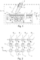
- the figure 1 shows a system 2 for recording the trace of the tip of a pencil 4 on a writing medium 6.
- the pencil 4 is freely movable directly by the hand of a human being in an XYZ frame fixed without any degree of freedom to the system 2.
- the X and Y directions of this frame are horizontal and the Z direction is vertical.
- the terms “above”, “below”, “upper”, “lower” relate to this vertical direction Z.
- the pencil 4 typically weighs less than 1 kg and, preferably, less than 200g or 100g. The dimensions of this pencil are also small enough that it can be held with one hand by a human being.
- the pencil 4 has an oblong shape. It extends along a longitudinal axis 7.
- this pencil 4 is made entirely from non-magnetic materials, that is to say materials exhibiting no magnetic properties that can be measured by the system 2.
- the pencil 4 is a conventional pencil which can be freely purchased commercially.
- the outer diameter of the body of the pencil 4 is therefore generally between 1.5 mm and 3 cm.
- it is chosen from the group consisting of a ballpoint pen, an ink pen, a fountain pen, a felt tip pen, a wooden pencil, a marker, a highlighter , a pen, a feather, a brush.
- the pencil 4 is a ballpoint pen.
- the pencil 4 has a tip 8 which deposits a liquid or a colored solid on an upper face 10 of the writing medium 6.
- the pencil 4 is provided with a reservoir of colored liquid such as a cartridge.
- the colored liquid can be ink.
- the tip 8 is located on the axis 7 at the lower end of the pencil 4. In this embodiment, the tip 8 has a symmetry of revolution around the axis 7. Thus, the angular position of the tip 8 around of axis 7 does not modify the width or the shape of the mark left by this point 8 on the support 6.
- the support 6 is a conventional writing medium having a non-zero thickness e in the Z direction.
- the thickness e is assumed to be constant over the entire face 10.
- the thickness e can be any. In particular, this thickness e can be very small, that is to say less than 1 mm or less than 0.5 mm in the case of a sheet of paper or of a canvas.
- the thickness e can also be very large, that is to say greater than 5 mm in the case of a notebook or a notepad.
- the support 6 can be rigid or flexible.
- a rigid support is a non-magnetically sensitive glass or metal plate.
- a flexible medium is a sheet of paper.
- the surface of the face 10 is large enough to allow writing or drawing. For this purpose, it is typically greater than 6 or 20 or 100 cm 2 .
- the support 6 also has a lower face 12 on the side opposite to the face 10.
- the system 2 comprises a magnetic ring 14 and a device 16 for locating the tip 8 in the XYZ frame from the measured position and orientation of the ring 14.
- the vertical wavy lines indicate that part of the apparatus 16 has not been shown.
- the ring 14 is fixed on the outer periphery of the body of the pencil 4. Typically, it surrounds the rigid body of non-magnetic material of the pencil 4.
- the ring 14 is described in more detail with reference to figure 3 .
- the apparatus 16 comprises a tablet 20 having a front face 22 for support and a rear face 24.
- This tablet is typically devoid of any electrical or electronic circuit. It is for example made from a single block of material.
- the face 22 extends horizontally.
- the lower face 12 of the support 6 is directly deposited on the face 22.
- the surface of the face 22 is large enough to allow writing or drawing. Typically, it is greater than 20 or 100 cm 2 .
- the tablet 20 is made of a non-magnetic material.
- the Young's modulus of tablet 20 is greater than 2 or 10 or 50 GPa at 25 ° C.
- its thickness is sufficient not to bend under the pressure exerted by the hand of the user when the latter writes using the pencil 4 on the support 6.
- the tablet 20 is a plate. glass with a thickness greater than 1 mm or 4 mm.
- the apparatus 16 comprises an array of N tri-axis magnetometers M ij .
- This network makes it possible to locate the ring 14 in the XYZ frame.
- location is meant here the determination of the position x, y, z of the ring 14 in the reference XYZ and also the determination of the orientation of the ring 14 with respect to the directions X, Y and Z of the reference XYZ .
- the orientation of ring 14 is represented by the angles ⁇ x , ⁇ y and ⁇ z of the magnetic moment of ring 14, respectively, with respect to the X, Y and Z axes of the frame.
- N is greater than five and, preferably, greater than sixteen or thirty-two.
- N is greater than or equal to sixty-four.
- the magnetometers M ij are aligned in rows and columns to form a matrix.
- this matrix has eight rows and eight columns.
- the indices i and j identify, respectively, the row and the column of this matrix at the intersection of which the magnetometer M ij is located.
- On the figure 1 only the magnetometers M i1 , M i2 , M i3 , M i4 and M i8 of a line i are visible.
- the position of the magnetometers M ij relative to each other is described in more detail with reference to figure 2 .
- Each magnetometer M ij is attached without any degree of freedom to the other magnetometers.
- the magnetometers M ij are fixed without any degree of freedom on the rear face 24 of the shelf 20.
- Each magnetometer M ij measures the direction and the intensity of the magnetic field generated by the ring 14. For this, each magnetometer M ij measures the norm of the orthogonal projection of the magnetic field generated by the ring 14 at the level of this magnetometer M ij on three measurement axes of this magnetometer. Here, these three measurement axes are orthogonal to each other. For example, the measurement axes of each of the magnetometers M ij are, respectively, parallel to the X, Y and Z directions of the reference frame.
- the sensitivity of the magnetometer M ij is for example less than 10 -6 T or 10 -7 T.
- Each magnetometer M ij is connected via an information transmission bus 28 to a processing unit 30.
- the processing unit 30 is capable of determining the position of the tip 8 on the support 6 from the measured position and orientation of the ring 14 in the reference frame XYZ by the magnetometers M ij .
- the unit 30 comprises a programmable electronic computer 32 capable of executing instructions recorded on an information recording medium.
- the unit 30 therefore also comprises a memory 34 containing the instructions necessary for the execution by the computer 32 of the method of the figure 5 .
- the unit 30 implements a mathematical model associating each measurement of a magnetometer M ij with the position and the orientation of the ring 14 in the reference frame XYZ.
- This model is implemented as an extended Kalman filter. This model is typically built from the physical equations of electromagnetism.
- ring 14 is approximated by a magnetic dipole. This approximation introduces very few errors if the distance between the ring 14 and the magnetometer M ij is greater than 2L and, preferably, greater than 3L, where L is the largest dimension of the ring 14. Typically, L is less than 7cm and, preferably, less than 4 or 2cm.
- the unit 30 is also capable of acquiring and recording the trace left by the tip 8 on the support 6 from the various positions determined for this tip.
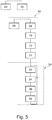
- the figure 2 represents a part of the magnetometers M ij of the apparatus 16. These magnetometers M ij are aligned in lines i parallel to the direction X. These magnetometers are also aligned in columns j parallel to the direction Y to form a matrix. Rows i and columns j are arranged in the order of increasing indices.
- the center of the magnetometer M ij is at the intersection of row i and column j.
- the center of the magnetometer is the point where the magnetic field is measured by this magnetometer.
- the indices i and j belong to the interval [1; 8].
- the centers of two immediately consecutive magnetometers M ij and M i, j + 1 along a line i are separated by a distance d i, j , j + 1 .
- the center of two magnetometers M ij and M i + 1,, j immediately consecutive along the same column j are separated by a distance d j, i , i + 1 .
- the distance d i, j , j + 1 is the same. This distance is therefore denoted by d j .
- the distance d j, i , i + 1 between two magnetometers is the same. This distance is therefore denoted by d i .
- the distances d i and d j are both equal to d.
- the figure 3 shows the ring 14 in more detail.
- the ring 14 has an overall magnetic moment parallel to the axis 7. In this embodiment, the magnetic moment of the ring 14 is coincident with or coaxial with the axis 7.
- This ring 14 has a cylindrical outer face 38 of circular cross section. The generatrix of this cylindrical outer face coincides with the axis 7.
- the ends of the ring 14 terminate in planes 40, 41 of ends each perpendicular to the axis 7.
- the length L of the ring 14 is therefore in this embodiment the shortest distance between the planes 40 and 41.
- This length L is preferably greater than the internal diameter ⁇ int of the ring 14 and, preferably, twice greater than ⁇ int .
- the length L of this ring is less than 15 cm, or less than 10 cm, or even 7 cm or 5 cm.
- the figure 4 shows the cross section of the ring 14.
- This ring 14 comprises an outer layer 44 of magnetic material and an inner layer 46 of elastic material.
- the layers 44 and 46 extend over the entire length L of the ring 14.
- Layer 44 is only produced by a magnetic material uniformly distributed around axis 7. This magnetic material forms an annular permanent magnet, the direction of the magnetic moment of which coincides with axis 7.
- the outer face of layer 44 corresponds to the outer face 38.
- This layer 44 also has an inner face 48 turned towards the axis 7.
- the thickness e44 of the layer 44 is defined as being the shortest distance between the faces 38 and 48. For example, the thickness e44 is greater than 0.5 or 1 mm and, generally, less than 1 cm or 5 mm. Here, the thickness e44 is constant.
- the magnetic material which makes up this layer 44 is a ferromagnetic or ferrimagnetic material. This material exhibits a magnetic moment not zero even in the absence of an external magnetic field. For example, this material has a coercive magnetic field greater than 100 Am -1 or 500 Am -1 . The power of this permanent magnet is typically greater than 0.01 Am 2 or 0.1 Am 2 .
- the layer 44 is made of a rigid magnetic material.
- rigid is meant a material whose Young's modulus at 25 ° C. is greater than 15 or 30 or 50 GPa. Under these conditions, the layer 44 cannot adapt to different pencil diameters.
- the layer 46 covers the internal face 48.
- This layer 46 has a cylindrical internal face 50, the generatrix of which coincides with the axis 7.
- This face 50 is intended to come to bear. directly onto the body of the pencil 4.
- the cross section of the face 50 is circular.
- This layer 46 is elastically deformable during the introduction of the rod 4 inside the ring 14 between a rest position, shown in solid lines on the figure 4 , and a deformed position, shown in dotted lines on the figure 4 .
- the rest position corresponds to a value of the internal diameter ⁇ int of between 1.5 mm and 3 cm and, preferably, between 5 mm and 1.5 cm.
- the deformed position corresponds to a greater value of the inside diameter ⁇ int equal to the outside diameter of the body of the rod 4.
- the difference between these two values, denoted ⁇ is typically greater than 1 mm or 2 mm.
- the layer 46 is uniformly made of an elastic material whose Young's modulus at 25 ° C. is less than or equal to 1 GPa and, preferably, less than or equal to 0.1 or 0.01 GPa.
- the elastic material is an elastomeric material or latex or a shape memory material.
- the thickness of the layer 46 in the radial direction is strictly greater than ⁇ .
- this thickness is greater than 2 or 4 mm.
- the device 16 continuously measures the position and the orientation of the ring 14 in the reference frame XYZ linked without any degree of freedom to the front face 22.
- the directions X and Y of this frame are contained in the plane of the front face 22. Consequently, the height, denoted h 0 , of the ring 14 with respect to the face 22 is equal to the value of the z coordinate of the ring 14 in the XYZ mark.
- the user fixes the ring 14 on the pencil 4. For example, for this, he introduces the point 8 in the center of the ring 14 then slides the pencil 4 to the inside the ring 14. Under the effect of this action, the rod 4 crushes the elastic layer 46 and pushes it back to its deformed position. This increases the internal diameter of the ring 14 without deforming the magnetic material.
- the elastic layer exerts on the body of the pencil 4 a restoring force which keeps the ring 14 in place as long as the pencil 4 is used.
- the user After positioning the ring 14 on the pencil 4, the user triggers a calibration phase 64.
- the user maintains the tip 8 of the pencil 4 in contact with the face 10 then moves the opposite end of the pencil 4 to modify its inclination relative to the support 6 without modifying the position of the point 8 on this support 6.
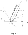
- the figure 12 represents two positions of the pen 4 obtained during step 66.
- the axis 7 corresponds to a first inclination while the axis 7a corresponds to a second inclination of the pen 4.
- the axis 7a has been shown for the second inclination.
- the computer 32 reads the position and the orientation of the ring 14 measured by the network of magnetometers.
- the computer 14 detects a bundle of orientations which all point towards the point of contact between the point 8 and the face 10 of the support 6. On the figure 12 , this point of contact bears the reference I t .
- the threshold S cp makes it possible to detect the contact of the tip 8 with the support 6. In fact, it is considered that there is a point of contact between the tip 8 and the support 6 if the height h p of the tip 8 with respect to at face 22 is less than or equal to the threshold S cp .
- This threshold S cp is a function of the thickness e of the support 6.
- the unit 30 calculates the point of intersection I t between the axes 7 and 7a. Preferably, for this, the unit 30 calculates the coordinates of the reference point XYZ which minimize the difference between the axes 7 and 7a.
- the height of the point of intersection I t with respect to the face 22 makes it possible to obtain an estimate of the thickness e of the support 6.
- the value of the threshold S cp is calculated from this estimate of the thickness e.
- the value of the threshold S cp is chosen equal to this estimate plus a margin of error ⁇ .
- the margin of error ⁇ is determined experimentally.
- ⁇ is here chosen less than or equal to 1mm or 0.5mm or 0.1mm or 0.05mm or 0.0025mm.
- the angle ⁇ and the value of the height h 0 are deduced from the readings taken during step 68. Once the distance “a” has been calculated, it is said to be “known”. It is saved in memory 34.
- the unit 30 proceeds to a phase 90 of recording the trace left by the pencil 4 on the face 10 of the support 6.
- the unit 30 calculates the position of the tip 8 in the XYZ frame from the position and the orientation measured of the ring 14 during the step 60 and from the known distance "a".
- the position of the tip at the moment when the latter is in contact with the face 10 is equal to the position of the point of contact.
- the position of the tip 8 is equal to the position of the ring 14 offset by the distance "a" in the direction of the magnetic moment of the ring 14.
- the angle ⁇ and the value of the height h 0 are measured during step 60.
- the coordinates of the position of the point 8 in the reference frame XYZ are here denoted x p , y p and z p .
- the coordinate z p is equal to the height h p ..
- the unit 30 detects the point of contact between the tip 8 and the face 10. For this, the unit 30 compares the height h p with the threshold S cp . A contact point is detected only when the height h p is less than the threshold S cp .
- the unit 30 detects the coordinates x p and y p at the moment when this point of contact occurs.
- the unit 30 records, for example in the memory 34, the position calculated for the tip 8 when the latter is in contact with the support 6.
- Steps 92 to 98 are repeated in a loop.
- the successive recording of the position of the point 8 on the face 10 constitutes the reading of the mark left by the point 8 on this support 6.
- each position of the point 8 when it is in contact with the support 6 is recorded in chronological order.
- the positions of the tip 8 when the latter is not in contact with the support 6 are recorded as not forming part of the trace left on the support 6.
- the figures 6 and 7 represent a ring 110 which can be used in system 2 instead of ring 14.
- This ring 110 is identical to ring 14 except that the layer 44 is replaced by a magnetic layer 112.
- This layer 112 is identical to the layer 44, except that the magnetic material is not continuously distributed around the axis 7.
- the layer 112 comprises N blocks 114 of magnetic materials. rigid mechanically separated from each other by segments 116 of elastic material, where N is an integer strictly greater than two. To simplify figures 6 and 7 , N is taken equal to two.
- the blocks 114 are all identical to each other and uniformly distributed over the periphery of the layer 46.
- the magnetic material of the blocks 114 is the same as that used to make the layer 44.
- the elastic material used to make the segments 116 is for example the same as that used for the layer 46.
- the layer 112 is covered with a layer 120 of elastic material.
- the material of the layer 120 is, for example, identical to that of the layer 46.
- the figure 6 shows the elastic material of segments 116 and layers 46 and 120 in its rest position and the figure 7 represents this same elastic material in its deformed position.
- the segments 116 widen so as to allow the different blocks 114 to move away from each other. This makes it possible to fix the ring 110 on rods of different diameters without deforming the blocks 114 of magnetic material.
- the figures 8 and 9 represent a ring 130 capable of being used in system 2. More precisely, the ring 130 is identical to the ring 110, except that the layers 44 and 120 are omitted and that the ring 130 is movable, in a reversible manner , directly by the user's hand, between an open position shown on the figure 8 and a closed position shown in figure 9 . On the figures 8 and 9 , the number N of blocks 114 is taken equal to seven.
- the ring 130 In the open position, the ring 130 forms a band 132 extending essentially in an X'Y 'plane where X' and Y 'are orthogonal directions, the Y' direction being parallel to the axis 7.
- the strip 132 In the position closed, the strip 132 is wound around the periphery of the body of the pencil 4 to form a closed magnetic ring.
- the strip 132 has two opposite ends, 134 and 136, in the X 'direction. In the open position, these ends are separated from each other by a distance strictly greater than the outside diameter of the body of the rod 4. In the closed position, these ends 134, 136 are superimposed on one another.
- the ends 134 and 136 are equipped with a locking mechanism able to lock the ring 130 in its closed position and, alternately, to allow the movement of the ring 130 to its open position.
- this locking mechanism consists of respective parts of hook-and-loop strips each attached to the ends 134 and 136.
- This self-gripping strip is also better known under the name VELCRO® or “Velcro® strip”.
- the segments 116 widen, which allows the strip 132 to be elongated when it is wound around the body of the rod 4 so that the ends 134 and 136 meet in the position. closed.
- the figure 10 represents an equipment 150 for the pencil 4.
- This equipment 150 comprises a magnetic ring 152 and two rigid shells 154 and 156.
- the shells 154, 156 are intended to maintain the direction of the magnetic moment of the ring 152 parallel to the axis 7 .
- the ring 152 is for example identical to the ring 14 except that its length L is less than the value of its diameter ⁇ int in its rest position.
- the shell 154 includes a housing 160 capable of clamping, without any degree of freedom, part of the ring 152. To make this housing more visible, on the figure 10 , a clearance is shown between this housing 160 and the ring 152. In reality, this clearance does not exist or is strictly less than 100 or 10 or 5 ⁇ m.
- the ends of the shell 154, opposite in the direction parallel to the axis 7, are each equipped with a first part, respectively 162, 164, with jaws 166, 168.
- the shells 154 and 156 are symmetrical to each other with respect to a plane of symmetry containing the axis 7.
- the shell 156 is deduced by symmetry from the shell 154.
- reference numerals 162 and 164 have been replaced by reference numerals 170 and 172.
- the shell 156 is mechanically connected to the shell 154 by a hinge 174 whose axis of rotation is parallel to the axis 7.
- the jaws 166 and 168 are separated from each other in a direction parallel to the axis 7 by a distance L c strictly greater than the value of the diameter ⁇ int in the rest position and, preferably, two or three times greater than this value.
- the distance L c is for example equal to the length L of the ring 14.
- Jaw 166 is movable between an open position, shown in figure 11 in solid line, and a closed position shown on the figure 11 dotted.
- the jaw 166 grips the body of the pencil 4.
- the jaw 166 releases the body of the pencil 4 so that this pencil 4 can be withdrawn from the jaws 166 and 168.
- the jaw 166 passes, from reversibly, between the closed position and the open position by pivoting around the axis of the hinge 174.
- jaw 168 is identical to jaw 166 except that it is located on the opposite side of the shell.
- the shells are also equipped with a means for locking the jaws 166 and 168 in their closed position.
- the shells 154 and 156 therefore make it possible to stabilize the ring 152 in a position where the direction of its magnetic moment coincides with the axis 7 when the jaws 166 and 168 are in their closed position.
- the outer face of the shells 154 and 156 covers the ring 152 and forms a means for gripping the pencil 4 while a user writes with this pencil 4.
- the magnetic material is not a permanent magnet but is made of a paramagnetic, diamagnetic or a soft ferromagnetic material.
- the section of the ring is not necessarily a circular section.
- the term “internal diameter” denotes the internal hydraulic diameter.
- the cross section of the ring can be any from the moment when it has a center in a plane perpendicular to the axis 7 located on the longitudinal axis.
- the cross section of the inner face can also be square, oval or rectangular.
- the overall magnetic moment of the ring is parallel to axis 7 but is not coincident with this axis.
- the quantity of magnetic material is not uniformly distributed around the axis 7.
- the blocks 114 located on one side of a plane containing the axis 7 exhibit stronger magnetic moments than those located on the other side of this same plane.
- the distribution of the magnetic material in the layer 44 is modified so as to obtain a ring having a magnetic moment parallel with the axis 7 but not coincident with this axis.
- the thickness of the layer 46 is not necessarily constant along the periphery of the face 48.
- the inner face 50 has pits and bumps greater than 0.5 mm in height in the rest position. to increase the coefficient of friction between the rod 4 and the ring 14.
- the ring locking mechanism 130 can be replaced by glues having a low adhesion such as those used for the production of adhesive butterflies better known under the English term of “Post-it”.
- the ring is not necessarily closed.
- the ring 14 is sawn on only one of its sides parallel to the axis 7.
Landscapes
- Engineering & Computer Science (AREA)
- Theoretical Computer Science (AREA)
- General Engineering & Computer Science (AREA)
- Physics & Mathematics (AREA)
- Human Computer Interaction (AREA)
- General Physics & Mathematics (AREA)
- Electromagnetism (AREA)
- Power Engineering (AREA)
- Credit Cards Or The Like (AREA)
- Measuring Magnetic Variables (AREA)
- Pens And Brushes (AREA)
- Position Input By Displaying (AREA)
- Mechanical Pencils And Projecting And Retracting Systems Therefor, And Multi-System Writing Instruments (AREA)
Claims (10)
- System für die Erfassung der Bahn eines Stifts (4) oder eines Radierers auf einer Schreibunterlage, das Folgendes umfasst:- einen magnetischen Ring (14; 110; 130; 152), der an dem Stift (4) oder dem Radierer befestigt werden kann, wobei dieser Ring Folgendes umfasst:- eine zylindrische Innenfläche (50), die auf die Längsachse zentriert ist, und eine Außenfläche (38) gegenüber der Innenfläche,- ein magnetisches Material, das in einer Schicht (44; 112), die "magnetische Schicht" genannt wird, um die Längsachse in der Weise verteilt ist, dass die Richtung des globalen magnetischen Moments des magnetischen Rings zu der Längsachse parallel ist,- eine Abstützfläche einer Platte (20), wobei diese Abstützfläche die Schreibunterlage bildet oder die Schreibunterlage trägt,dadurch gekennzeichnet, dass:- der magnetische Ring (14; 110; 130; 152) an dem Stift (4) oder dem Radierer abnehmbar befestigt werden kann,- der kleinste Innendurchmesser des Rings im Bereich von 1,5 mm bis 3 cm liegt und- der Ring ein elastisches Material (46; 116) aufweist, das von dem magnetischen Material verschieden ist und elastisch verformbar ist zwischen:• einer Ruheposition, die einem ersten Wert des Innendurchmessers des Rings entspricht, und• einer verformten Position, die einem zweiten Wert des Innendurchmessers des Rings entspricht, wobei der Abstand zwischen dem ersten und dem zweiten Wert des Innendurchmessers größer oder gleich 1 mm ist, wobei dieses elastische Material einen Elastizitätsmodul bei 25 °C, der kleiner oder gleich 1 GPa ist, aufweist,- wobei das System Folgendes umfasst:• ein Magnetometernetz, das das Magnetfeld, das durch den magnetischen Ring erzeugt wird, messen kann, wobei dieses Magnetometernetz ohne jeden Freiheitsgrad an der Abstützfläche der Platte (20) befestigt ist,• einen Rechner (32), der die Position und die Orientierung des magnetischen Rings bestimmen kann, um daraus die Position der Spitze des Stifts (4) oder des Radierers in Bezug auf die Abstützfläche anhand von Messungen des Magnetometernetzes abzuleiten.
- Magnetischer Ring, der dafür ausgelegt ist, in einem System nach Anspruch 1 betrieben zu werden, wobei dieser magnetische Ring an einem Stift (4) oder an einem Radierer befestigt werden kann, wobei dieser Ring Folgendes umfasst:- eine zylindrische Innenfläche (50), die auf die Längsachse zentriert ist, und eine Außenfläche (38) gegenüber der Innenfläche,- ein magnetisches Material, das in einer Schicht (44; 112), die "magnetische Schicht" genannt wird, um die Längsachse in der Weise verteilt ist, dass die Richtung des globalen magnetischen Moments des magnetischen Rings zu der Längsachse parallel ist,dadurch gekennzeichnet, dass:- der magnetische Ring an dem Stift (4) oder dem Radierer abnehmbar befestigt werden kann,- der kleinste Innendurchmesser des Rings im Bereich von 1,5 mm bis 3 cm liegt,- der Ring ein elastisches Material (46; 116) enthält, das von dem magnetischen Material verschieden ist und elastisch verformbar ist zwischen:• einer Ruheposition, die einem ersten Wert des Innendurchmessers des Rings entspricht, und• einer verformten Position, die einem zweiten Wert des Innendurchmessers des Rings entspricht, wobei der Abstand zwischen dem ersten und dem zweiten Wert des Innendurchmessers größer oder gleich 1 mm ist, wobei dieses elastische Material einen Elastizitätsmodul bei 25 °C, der kleiner oder gleich 1 GPa ist, aufweist.
- Ring, der dafür ausgelegt ist, in einem System nach Anspruch 1 oder einem Ring nach Anspruch 2 betrieben zu werden, wobei:- der magnetische Ring sich innerhalb der magnetischen Schicht (44) um die Längsachse ununterbrochen über einen Winkelsektor senkrecht zu dieser Längsachse, dessen Scheitel auf der Längsachse liegt, der streng größer als 180° oder 220° ist, erstreckt und- das elastische Material zwischen der magnetischen Schicht und der Innenfläche des Rings in der Weise verteilt ist, dass eine elastische Schicht (46) gebildet wird, deren Dicke in einer Richtung senkrecht zu der Längsachse größer als 1 mm ist.
- Ring, der dafür ausgelegt ist, in einem System nach Anspruch 1 oder einem Ring nach Anspruch 2 betrieben zu werden, wobei innerhalb der magnetischen Schicht (112) das magnetische Material in mehreren nicht miteinander verbundenen Blöcken (114) verteilt ist und das elastische Material sich zwischen diesen Blöcken befindet.
- Ring, der dafür ausgelegt ist, in einem System nach Anspruch 1 oder einem Ring nach einem der Ansprüche 2 bis 4 betrieben zu werden, wobei der Ring zwei Enden (134, 136) aufweist und auf eine durch einen Menschen umkehrbare Weise verformbar ist zwischen:- einer offenen Position, in der die beiden Enden voneinander um eine Strecke beabstandet sind, die größer als der erste Wert des Innendurchmessers des Rings ist, derart, dass der Ring geöffnet ist, und- einer geschlossenen Position, in der die beiden Enden mechanisch miteinander verbunden sind, derart, dass der Ring geschlossen ist.
- Ring nach Anspruch 5, wobei der Ring einen Verriegelungsmechanismus enthält, der sich verlagern kann zwischen:- einer verriegelten Position, in der dieser Mechanismus den Ring in seiner geschlossenen Position hält, und- einer entriegelten Position, in der der Mechanismus die Verlagerung des Rings in seine offene Position zulässt.
- Ring nach Anspruch 6, wobei der Verriegelungsmechanismus ein Klettband enthält.
- Ring, der dafür ausgelegt ist, in einem System nach Anspruch 1 oder einem Ring nach einem der Ansprüche 2 bis 7 betrieben zu werden, wobei die Länge des Rings parallel zu der Längsachse zumindest größer als der größtmögliche Wert des Innendurchmessers dieses Rings ist.
- Ring, der dafür ausgelegt ist, in einem System nach Anspruch 1 oder einem Ring nach einem der Ansprüche 2 bis 8 betrieben zu werden, wobei das magnetische Material einen Elastizitätsmodul bei 25 °C, der größer als 20 GPa ist, aufweist.
- Ausrüstung für einen Stift (4) oder einen Radierer, wobei diese Ausrüstung Folgendes umfasst:- einen magnetischen Ring (152), der eine zylindrische Innenfläche, die auf eine Längsachse zentriert ist, besitzt,- wenigstens eine starre Schale (154, 156), die einen Aufnahmeraum (160) aufweist, der so geformt ist, dass er den magnetischen Ring aufnehmen kann und die Längsachse des magnetischen Rings, der in diesem Aufnahmeraum aufgenommen ist, parallel zu einer Längsachse des Stifts (4) oder des Radierers halten kann, wenn diese Schale ohne jeden Freiheitsgrad an diesem Stift (4) oder diesem Radierer befestigt ist,- eine erste und eine zweite Klemmbacke (166, 168), wobei jede Klemmbacke einen ersten und einen zweiten Teil (162, 164, 170, 172) aufweist, die verlagerbar sind zwischen:• einer geschlossenen Position, in der der erste und der zweite Teil den Stift (4) oder den Radierer umschließen können, um die Schale an diesem Stift (4) oder diesem Radierer zu befestigen, und• einer offenen Position, in der der erste und der zweite Teil den Stift (4) oder den Radierer freigeben, wobei die erste und die zweite Klemmbacke ohne jeden Freiheitsgrad an der wenigstens einen Schale befestigt sind und in einer Richtung parallel zu der Längsachse des magnetischen Rings um eine Strecke beabstandet sind, die wenigstens zweimal größer als der größtmögliche Wert des Innendurchmessers des magnetischen Rings ist,dadurch gekennzeichnet, dass der magnetische Ring wie in einem der Ansprüche 2 bis 9 beschaffen ist.
Applications Claiming Priority (2)
| Application Number | Priority Date | Filing Date | Title |
|---|---|---|---|
| FR1259525A FR2996653B1 (fr) | 2012-10-05 | 2012-10-05 | Anneau magnetique apte a etre fixe de facon amovible sur un crayon ou un effaceur |
| PCT/EP2013/070504 WO2014053526A2 (fr) | 2012-10-05 | 2013-10-02 | Anneau magnetique apte a etre fixe de façon amovible sur un crayon ou un effaceur |
Publications (2)
| Publication Number | Publication Date |
|---|---|
| EP2904475A2 EP2904475A2 (de) | 2015-08-12 |
| EP2904475B1 true EP2904475B1 (de) | 2020-12-16 |
Family
ID=47666236
Family Applications (1)
| Application Number | Title | Priority Date | Filing Date |
|---|---|---|---|
| EP13770937.4A Active EP2904475B1 (de) | 2012-10-05 | 2013-10-02 | Vorübergehend an einem stift oder radierer anbringbarer magnetischer ring |
Country Status (5)
| Country | Link |
|---|---|
| US (1) | US9396859B2 (de) |
| EP (1) | EP2904475B1 (de) |
| JP (1) | JP6096910B2 (de) |
| FR (1) | FR2996653B1 (de) |
| WO (1) | WO2014053526A2 (de) |
Families Citing this family (11)
| Publication number | Priority date | Publication date | Assignee | Title |
|---|---|---|---|---|
| JP6619179B2 (ja) * | 2014-10-02 | 2019-12-11 | 公益財団法人電磁材料研究所 | 位置・姿勢検出装置 |
| FR3054040B1 (fr) | 2016-07-13 | 2018-08-17 | ISKn | Procede d’estimation d’une deviation angulaire moyenne entre l’axe magnetique et un axe de reference d’un objet magnetique |
| FR3067138B1 (fr) | 2017-05-31 | 2019-07-26 | ISKn | Procede d’estimation de la position d’un aimant comportant une phase d’identification d’un perturbateur magnetique |
| FR3067139B1 (fr) | 2017-05-31 | 2019-09-27 | ISKn | Procede de suivi d’un aimant par un reseau de magnetometres, comportant une phase d’identification de la presence de l’aimant et d’un perturbateur magnetique |
| FR3098955B1 (fr) | 2019-07-19 | 2021-07-23 | ISKn | Procédé de commande d’une interface graphique pour afficher le lancer d’un projectile dans un environnement virtuel |
| FR3101717B1 (fr) | 2019-10-04 | 2021-09-10 | ISKn | système de relevé d’une trace effectuee par un ustensile sur une surface d’écriture |
| FR3114413B1 (fr) * | 2020-09-21 | 2023-06-09 | Advanced Magnetic Interaction Ami | Procédé et dispositif de suivi d’une extrémite d’un ustensile comportant une recalibration d’une distance entre l’extrémité et un objet magnétique solidaire de l’ustensile |
| CN112929330A (zh) * | 2021-01-19 | 2021-06-08 | 山东万博科技股份有限公司 | 一种网间数据安全交换装置 |
| EP4350706A1 (de) | 2022-10-07 | 2024-04-10 | BIC Violex Single Member S.A. | Schreibsystem |
| EP4360903A1 (de) * | 2022-10-27 | 2024-05-01 | BIC Violex Single Member S.A. | Zeichensystem |
| US20260048609A1 (en) * | 2024-08-15 | 2026-02-19 | Jaron Solis | Contractor pencil sleeve having a magnet and hook and loop fastener |
Citations (2)
| Publication number | Priority date | Publication date | Assignee | Title |
|---|---|---|---|---|
| FR2988874A1 (fr) * | 2012-03-29 | 2013-10-04 | Commissariat Energie Atomique | Procede de detection d'un point de contact entre une pointe d'un ustensile et un support d'ecriture |
| FR2988862A1 (fr) * | 2012-03-29 | 2013-10-04 | Commissariat Energie Atomique | Procede et dispositif de localisation d'un objet magnetique |
Family Cites Families (18)
| Publication number | Priority date | Publication date | Assignee | Title |
|---|---|---|---|---|
| FR1252880A (fr) | 1959-10-08 | 1961-02-03 | Financ De La Cellulose S A Hol | Perfectionnements aux sacs d'emballage en matière plastique |
| FR1252881A (fr) | 1960-02-16 | 1961-02-03 | Controls Co Of America | Procédé et moule d'enrobage de bobines électriques ou autres objets |
| JPS59107297U (ja) * | 1983-01-08 | 1984-07-19 | 富士通株式会社 | 電子黒板用消去器 |
| JPS6014981U (ja) * | 1983-07-07 | 1985-01-31 | 株式会社井上ジャパックス研究所 | 筆記具 |
| JPS60186924A (ja) * | 1984-03-06 | 1985-09-24 | Wacom Co Ltd | デイスプレイ付座標入力装置 |
| FR2586302B1 (fr) * | 1985-08-13 | 1988-02-12 | Commissariat Energie Atomique | Procede pour localiser un objet et determiner son orientation dans l'espace et dispositif de mise en oeuvre |
| JPH07271509A (ja) * | 1994-03-28 | 1995-10-20 | Fuji Facom Corp | 座標入力用指示具 |
| JP3047342U (ja) * | 1997-09-19 | 1998-04-10 | 弘勝 大澤 | 筆記具用グリップ |
| JP2938446B1 (ja) * | 1998-09-10 | 1999-08-23 | 北川工業株式会社 | 雑音電流吸収具 |
| JP2001249767A (ja) * | 2000-03-03 | 2001-09-14 | Casio Comput Co Ltd | データ入力装置、及び記憶媒体 |
| JP3964167B2 (ja) * | 2001-08-01 | 2007-08-22 | 独立行政法人科学技術振興機構 | 位置・姿勢検出装置及びそれを用いたコンピュータ情報入力装置 |
| WO2005024620A2 (de) * | 2003-09-11 | 2005-03-17 | Siemens Aktiengesellschaft | Anzeigevorrichtung mit einrichtungen zum erzeugen und erfassen eines magnetfeldes und diese verwendendes gerät |
| US20050062730A1 (en) * | 2003-09-19 | 2005-03-24 | Henryk Birecki | Ergonomic pointing device |
| JP2007027446A (ja) * | 2005-07-19 | 2007-02-01 | Daido Electronics Co Ltd | 複合磁石シート |
| WO2008070147A1 (en) * | 2006-12-05 | 2008-06-12 | Kelvin Geis | A hand based support device for handheld implements and associated methods |
| US20110086335A1 (en) * | 2009-10-13 | 2011-04-14 | Rogers Michael H | Wear and write dry-erase notepad |
| JP2011100221A (ja) * | 2009-11-04 | 2011-05-19 | Seiko Epson Corp | 情報処理装置 |
| FR2952450B1 (fr) * | 2009-11-12 | 2012-06-08 | Commissariat Energie Atomique | Dispositif portable et procede d'impression d'une image, support d'enregistrement, stylo et borne pour ce dispositif |
-
2012
- 2012-10-05 FR FR1259525A patent/FR2996653B1/fr not_active Expired - Fee Related
-
2013
- 2013-10-02 WO PCT/EP2013/070504 patent/WO2014053526A2/fr not_active Ceased
- 2013-10-02 EP EP13770937.4A patent/EP2904475B1/de active Active
- 2013-10-02 JP JP2015535001A patent/JP6096910B2/ja active Active
- 2013-10-02 US US14/433,767 patent/US9396859B2/en active Active
Patent Citations (2)
| Publication number | Priority date | Publication date | Assignee | Title |
|---|---|---|---|---|
| FR2988874A1 (fr) * | 2012-03-29 | 2013-10-04 | Commissariat Energie Atomique | Procede de detection d'un point de contact entre une pointe d'un ustensile et un support d'ecriture |
| FR2988862A1 (fr) * | 2012-03-29 | 2013-10-04 | Commissariat Energie Atomique | Procede et dispositif de localisation d'un objet magnetique |
Also Published As
| Publication number | Publication date |
|---|---|
| JP6096910B2 (ja) | 2017-03-15 |
| US9396859B2 (en) | 2016-07-19 |
| US20150279537A1 (en) | 2015-10-01 |
| EP2904475A2 (de) | 2015-08-12 |
| JP2015532484A (ja) | 2015-11-09 |
| FR2996653A1 (fr) | 2014-04-11 |
| WO2014053526A3 (fr) | 2015-04-23 |
| FR2996653B1 (fr) | 2015-01-02 |
| WO2014053526A2 (fr) | 2014-04-10 |
Similar Documents
| Publication | Publication Date | Title |
|---|---|---|
| EP2904475B1 (de) | Vorübergehend an einem stift oder radierer anbringbarer magnetischer ring | |
| EP2811383B1 (de) | System, Werkzeug, Gerät, Verfahren und Informationsaufzeichnungsmedium zur Aufnahme des Spurverlaufs auf einer Schreibunterlage | |
| EP2831711B1 (de) | Verfahren zur erkennung eines kontaktpunktes zwischen einer instrumentenspitze und einer schreibunterlage | |
| EP2831641B1 (de) | Verfahren und vorrichtung zur lokalisierung eines magnetischen objekts | |
| WO1986005273A1 (fr) | Dispositif optique de detection d'effort, procede de mesure d'effort au moyen dudit dispositif et leur application a une balance | |
| WO2014016526A1 (fr) | Dispositif et procede de caracterisation d'un echantillon par des mesures localisees | |
| EP2965106B1 (de) | Verfahren zur automatischen erkennung eines magnetischen objekts | |
| EP4038482B1 (de) | System zur erfassung eines von einem gerät auf einer schreiboberfläche zurückgelegten weges, und entsprechendes verfahren und informations-aufzeichnungsmedium | |
| EP2923227A2 (de) | Verfahren zur automatischen erkennung eines bewegten magnetischen objekts | |
| EP2831705A2 (de) | Bildschirm mit magnetischer objektfindung | |
| FR3054040A1 (fr) | Procede d’estimation d’une deviation angulaire moyenne entre l’axe magnetique et un axe de reference d’un objet magnetique | |
| EP1443299A1 (de) | Taststift mit einstellbarer Orientierung | |
| EP3230771B1 (de) | Verfahren zur ortung von mindestens einem beweglichen magnetischen objekt und zugehöriges system | |
| EP1443302A2 (de) | Lenkbarer Taststift | |
| EP1617171A1 (de) | 3-D Taster | |
| EP3230772A1 (de) | Verfahren zur ortung von mindestens einem beweglichen magnetischen objekt und zugehöriges system | |
| EP1907220A2 (de) | Elektronischer stift mit dreidimensionalem kraftsensor | |
| EP4214598B1 (de) | Verfahren und vorrichtung zur verfolgung eines endes eines utensils mit rekalibrierung eines abstandes zwischen dem ende und einem am utensil sicher befestigten magnetischen objekt | |
| EP2409118A2 (de) | Einrichtung zur magnetischen messung der rotation einer magnetisierten kugel und verfahren zur messung der rotation der kugel | |
| EP1248073A1 (de) | Verfahren zur Bestimmung der Grösse der Deformation eines Taststiftes | |
| WO2005088434A1 (fr) | Procede de reconnaissance de la trajectoire d’une pointe d’un corps sur un support | |
| EP2939059A1 (de) | Vorrichtung zur markierung einer probe sowie beobachtungssystem mit solch einer markierungsvorrichtung | |
| TWI314640B (en) | Vernier tyre non-contact diameter measuring device for a roller/cylinder with rubber surface and a measuring system of using the same | |
| FR2774759A1 (fr) | Appareil et procede pour relever et rapporter sur un support graphique une position angulaire d'une ligne geometrique | |
| FR2865423A1 (fr) | Dispositif de guidage et d'orientation angulaire a monter sur le corps d'un outil portatif perforateur ou de percage. |
Legal Events
| Date | Code | Title | Description |
|---|---|---|---|
| PUAI | Public reference made under article 153(3) epc to a published international application that has entered the european phase |
Free format text: ORIGINAL CODE: 0009012 |
|
| 17P | Request for examination filed |
Effective date: 20150327 |
|
| AK | Designated contracting states |
Kind code of ref document: A2 Designated state(s): AL AT BE BG CH CY CZ DE DK EE ES FI FR GB GR HR HU IE IS IT LI LT LU LV MC MK MT NL NO PL PT RO RS SE SI SK SM TR |
|
| AX | Request for extension of the european patent |
Extension state: BA ME |
|
| DAX | Request for extension of the european patent (deleted) | ||
| 17Q | First examination report despatched |
Effective date: 20160622 |
|
| STAA | Information on the status of an ep patent application or granted ep patent |
Free format text: STATUS: EXAMINATION IS IN PROGRESS |
|
| GRAP | Despatch of communication of intention to grant a patent |
Free format text: ORIGINAL CODE: EPIDOSNIGR1 |
|
| STAA | Information on the status of an ep patent application or granted ep patent |
Free format text: STATUS: GRANT OF PATENT IS INTENDED |
|
| INTG | Intention to grant announced |
Effective date: 20200707 |
|
| GRAS | Grant fee paid |
Free format text: ORIGINAL CODE: EPIDOSNIGR3 |
|
| GRAA | (expected) grant |
Free format text: ORIGINAL CODE: 0009210 |
|
| STAA | Information on the status of an ep patent application or granted ep patent |
Free format text: STATUS: THE PATENT HAS BEEN GRANTED |
|
| AK | Designated contracting states |
Kind code of ref document: B1 Designated state(s): AL AT BE BG CH CY CZ DE DK EE ES FI FR GB GR HR HU IE IS IT LI LT LU LV MC MK MT NL NO PL PT RO RS SE SI SK SM TR |
|
| REG | Reference to a national code |
Ref country code: GB Ref legal event code: FG4D Free format text: NOT ENGLISH |
|
| REG | Reference to a national code |
Ref country code: IE Ref legal event code: FG4D Free format text: LANGUAGE OF EP DOCUMENT: FRENCH |
|
| REG | Reference to a national code |
Ref country code: DE Ref legal event code: R096 Ref document number: 602013074750 Country of ref document: DE |
|
| REG | Reference to a national code |
Ref country code: AT Ref legal event code: REF Ref document number: 1346191 Country of ref document: AT Kind code of ref document: T Effective date: 20210115 |
|
| PG25 | Lapsed in a contracting state [announced via postgrant information from national office to epo] |
Ref country code: GR Free format text: LAPSE BECAUSE OF FAILURE TO SUBMIT A TRANSLATION OF THE DESCRIPTION OR TO PAY THE FEE WITHIN THE PRESCRIBED TIME-LIMIT Effective date: 20210317 Ref country code: RS Free format text: LAPSE BECAUSE OF FAILURE TO SUBMIT A TRANSLATION OF THE DESCRIPTION OR TO PAY THE FEE WITHIN THE PRESCRIBED TIME-LIMIT Effective date: 20201216 Ref country code: FI Free format text: LAPSE BECAUSE OF FAILURE TO SUBMIT A TRANSLATION OF THE DESCRIPTION OR TO PAY THE FEE WITHIN THE PRESCRIBED TIME-LIMIT Effective date: 20201216 Ref country code: NO Free format text: LAPSE BECAUSE OF FAILURE TO SUBMIT A TRANSLATION OF THE DESCRIPTION OR TO PAY THE FEE WITHIN THE PRESCRIBED TIME-LIMIT Effective date: 20210316 |
|
| REG | Reference to a national code |
Ref country code: AT Ref legal event code: MK05 Ref document number: 1346191 Country of ref document: AT Kind code of ref document: T Effective date: 20201216 |
|
| REG | Reference to a national code |
Ref country code: NL Ref legal event code: MP Effective date: 20201216 |
|
| PG25 | Lapsed in a contracting state [announced via postgrant information from national office to epo] |
Ref country code: SE Free format text: LAPSE BECAUSE OF FAILURE TO SUBMIT A TRANSLATION OF THE DESCRIPTION OR TO PAY THE FEE WITHIN THE PRESCRIBED TIME-LIMIT Effective date: 20201216 Ref country code: LV Free format text: LAPSE BECAUSE OF FAILURE TO SUBMIT A TRANSLATION OF THE DESCRIPTION OR TO PAY THE FEE WITHIN THE PRESCRIBED TIME-LIMIT Effective date: 20201216 Ref country code: BG Free format text: LAPSE BECAUSE OF FAILURE TO SUBMIT A TRANSLATION OF THE DESCRIPTION OR TO PAY THE FEE WITHIN THE PRESCRIBED TIME-LIMIT Effective date: 20210316 |
|
| PG25 | Lapsed in a contracting state [announced via postgrant information from national office to epo] |
Ref country code: NL Free format text: LAPSE BECAUSE OF FAILURE TO SUBMIT A TRANSLATION OF THE DESCRIPTION OR TO PAY THE FEE WITHIN THE PRESCRIBED TIME-LIMIT Effective date: 20201216 Ref country code: HR Free format text: LAPSE BECAUSE OF FAILURE TO SUBMIT A TRANSLATION OF THE DESCRIPTION OR TO PAY THE FEE WITHIN THE PRESCRIBED TIME-LIMIT Effective date: 20201216 |
|
| REG | Reference to a national code |
Ref country code: LT Ref legal event code: MG9D |
|
| PG25 | Lapsed in a contracting state [announced via postgrant information from national office to epo] |
Ref country code: RO Free format text: LAPSE BECAUSE OF FAILURE TO SUBMIT A TRANSLATION OF THE DESCRIPTION OR TO PAY THE FEE WITHIN THE PRESCRIBED TIME-LIMIT Effective date: 20201216 Ref country code: SK Free format text: LAPSE BECAUSE OF FAILURE TO SUBMIT A TRANSLATION OF THE DESCRIPTION OR TO PAY THE FEE WITHIN THE PRESCRIBED TIME-LIMIT Effective date: 20201216 Ref country code: PT Free format text: LAPSE BECAUSE OF FAILURE TO SUBMIT A TRANSLATION OF THE DESCRIPTION OR TO PAY THE FEE WITHIN THE PRESCRIBED TIME-LIMIT Effective date: 20210416 Ref country code: LT Free format text: LAPSE BECAUSE OF FAILURE TO SUBMIT A TRANSLATION OF THE DESCRIPTION OR TO PAY THE FEE WITHIN THE PRESCRIBED TIME-LIMIT Effective date: 20201216 Ref country code: SM Free format text: LAPSE BECAUSE OF FAILURE TO SUBMIT A TRANSLATION OF THE DESCRIPTION OR TO PAY THE FEE WITHIN THE PRESCRIBED TIME-LIMIT Effective date: 20201216 Ref country code: EE Free format text: LAPSE BECAUSE OF FAILURE TO SUBMIT A TRANSLATION OF THE DESCRIPTION OR TO PAY THE FEE WITHIN THE PRESCRIBED TIME-LIMIT Effective date: 20201216 Ref country code: CZ Free format text: LAPSE BECAUSE OF FAILURE TO SUBMIT A TRANSLATION OF THE DESCRIPTION OR TO PAY THE FEE WITHIN THE PRESCRIBED TIME-LIMIT Effective date: 20201216 |
|
| PG25 | Lapsed in a contracting state [announced via postgrant information from national office to epo] |
Ref country code: PL Free format text: LAPSE BECAUSE OF FAILURE TO SUBMIT A TRANSLATION OF THE DESCRIPTION OR TO PAY THE FEE WITHIN THE PRESCRIBED TIME-LIMIT Effective date: 20201216 Ref country code: AT Free format text: LAPSE BECAUSE OF FAILURE TO SUBMIT A TRANSLATION OF THE DESCRIPTION OR TO PAY THE FEE WITHIN THE PRESCRIBED TIME-LIMIT Effective date: 20201216 |
|
| REG | Reference to a national code |
Ref country code: DE Ref legal event code: R097 Ref document number: 602013074750 Country of ref document: DE |
|
| PG25 | Lapsed in a contracting state [announced via postgrant information from national office to epo] |
Ref country code: IS Free format text: LAPSE BECAUSE OF FAILURE TO SUBMIT A TRANSLATION OF THE DESCRIPTION OR TO PAY THE FEE WITHIN THE PRESCRIBED TIME-LIMIT Effective date: 20210416 |
|
| PLBE | No opposition filed within time limit |
Free format text: ORIGINAL CODE: 0009261 |
|
| STAA | Information on the status of an ep patent application or granted ep patent |
Free format text: STATUS: NO OPPOSITION FILED WITHIN TIME LIMIT |
|
| PG25 | Lapsed in a contracting state [announced via postgrant information from national office to epo] |
Ref country code: IT Free format text: LAPSE BECAUSE OF FAILURE TO SUBMIT A TRANSLATION OF THE DESCRIPTION OR TO PAY THE FEE WITHIN THE PRESCRIBED TIME-LIMIT Effective date: 20201216 Ref country code: AL Free format text: LAPSE BECAUSE OF FAILURE TO SUBMIT A TRANSLATION OF THE DESCRIPTION OR TO PAY THE FEE WITHIN THE PRESCRIBED TIME-LIMIT Effective date: 20201216 |
|
| 26N | No opposition filed |
Effective date: 20210917 |
|
| PG25 | Lapsed in a contracting state [announced via postgrant information from national office to epo] |
Ref country code: ES Free format text: LAPSE BECAUSE OF FAILURE TO SUBMIT A TRANSLATION OF THE DESCRIPTION OR TO PAY THE FEE WITHIN THE PRESCRIBED TIME-LIMIT Effective date: 20201216 Ref country code: DK Free format text: LAPSE BECAUSE OF FAILURE TO SUBMIT A TRANSLATION OF THE DESCRIPTION OR TO PAY THE FEE WITHIN THE PRESCRIBED TIME-LIMIT Effective date: 20201216 |
|
| PG25 | Lapsed in a contracting state [announced via postgrant information from national office to epo] |
Ref country code: SI Free format text: LAPSE BECAUSE OF FAILURE TO SUBMIT A TRANSLATION OF THE DESCRIPTION OR TO PAY THE FEE WITHIN THE PRESCRIBED TIME-LIMIT Effective date: 20201216 |
|
| PG25 | Lapsed in a contracting state [announced via postgrant information from national office to epo] |
Ref country code: IS Free format text: LAPSE BECAUSE OF FAILURE TO SUBMIT A TRANSLATION OF THE DESCRIPTION OR TO PAY THE FEE WITHIN THE PRESCRIBED TIME-LIMIT Effective date: 20210416 |
|
| REG | Reference to a national code |
Ref country code: CH Ref legal event code: PL |
|
| REG | Reference to a national code |
Ref country code: BE Ref legal event code: MM Effective date: 20211031 |
|
| PG25 | Lapsed in a contracting state [announced via postgrant information from national office to epo] |
Ref country code: MC Free format text: LAPSE BECAUSE OF FAILURE TO SUBMIT A TRANSLATION OF THE DESCRIPTION OR TO PAY THE FEE WITHIN THE PRESCRIBED TIME-LIMIT Effective date: 20201216 |
|
| PG25 | Lapsed in a contracting state [announced via postgrant information from national office to epo] |
Ref country code: BE Free format text: LAPSE BECAUSE OF NON-PAYMENT OF DUE FEES Effective date: 20211031 Ref country code: LU Free format text: LAPSE BECAUSE OF NON-PAYMENT OF DUE FEES Effective date: 20211002 |
|
| PG25 | Lapsed in a contracting state [announced via postgrant information from national office to epo] |
Ref country code: LI Free format text: LAPSE BECAUSE OF NON-PAYMENT OF DUE FEES Effective date: 20211031 Ref country code: CH Free format text: LAPSE BECAUSE OF NON-PAYMENT OF DUE FEES Effective date: 20211031 |
|
| PG25 | Lapsed in a contracting state [announced via postgrant information from national office to epo] |
Ref country code: IE Free format text: LAPSE BECAUSE OF NON-PAYMENT OF DUE FEES Effective date: 20211002 |
|
| PG25 | Lapsed in a contracting state [announced via postgrant information from national office to epo] |
Ref country code: HU Free format text: LAPSE BECAUSE OF FAILURE TO SUBMIT A TRANSLATION OF THE DESCRIPTION OR TO PAY THE FEE WITHIN THE PRESCRIBED TIME-LIMIT; INVALID AB INITIO Effective date: 20131002 |
|
| PG25 | Lapsed in a contracting state [announced via postgrant information from national office to epo] |
Ref country code: CY Free format text: LAPSE BECAUSE OF FAILURE TO SUBMIT A TRANSLATION OF THE DESCRIPTION OR TO PAY THE FEE WITHIN THE PRESCRIBED TIME-LIMIT Effective date: 20201216 |
|
| PG25 | Lapsed in a contracting state [announced via postgrant information from national office to epo] |
Ref country code: MK Free format text: LAPSE BECAUSE OF FAILURE TO SUBMIT A TRANSLATION OF THE DESCRIPTION OR TO PAY THE FEE WITHIN THE PRESCRIBED TIME-LIMIT Effective date: 20201216 |
|
| PG25 | Lapsed in a contracting state [announced via postgrant information from national office to epo] |
Ref country code: MT Free format text: LAPSE BECAUSE OF FAILURE TO SUBMIT A TRANSLATION OF THE DESCRIPTION OR TO PAY THE FEE WITHIN THE PRESCRIBED TIME-LIMIT Effective date: 20201216 |
|
| PG25 | Lapsed in a contracting state [announced via postgrant information from national office to epo] |
Ref country code: TR Free format text: LAPSE BECAUSE OF FAILURE TO SUBMIT A TRANSLATION OF THE DESCRIPTION OR TO PAY THE FEE WITHIN THE PRESCRIBED TIME-LIMIT Effective date: 20201216 |
|
| PGFP | Annual fee paid to national office [announced via postgrant information from national office to epo] |
Ref country code: DE Payment date: 20251020 Year of fee payment: 13 |
|
| PGFP | Annual fee paid to national office [announced via postgrant information from national office to epo] |
Ref country code: GB Payment date: 20251029 Year of fee payment: 13 |
|
| PGFP | Annual fee paid to national office [announced via postgrant information from national office to epo] |
Ref country code: FR Payment date: 20251024 Year of fee payment: 13 |