EP4038482B1 - System zur erfassung eines von einem gerät auf einer schreiboberfläche zurückgelegten weges, und entsprechendes verfahren und informations-aufzeichnungsmedium - Google Patents
System zur erfassung eines von einem gerät auf einer schreiboberfläche zurückgelegten weges, und entsprechendes verfahren und informations-aufzeichnungsmedium Download PDFInfo
- Publication number
- EP4038482B1 EP4038482B1 EP20780215.8A EP20780215A EP4038482B1 EP 4038482 B1 EP4038482 B1 EP 4038482B1 EP 20780215 A EP20780215 A EP 20780215A EP 4038482 B1 EP4038482 B1 EP 4038482B1
- Authority
- EP
- European Patent Office
- Prior art keywords
- writing surface
- tip
- contact
- pixels
- trace
- Prior art date
- Legal status (The legal status is an assumption and is not a legal conclusion. Google has not performed a legal analysis and makes no representation as to the accuracy of the status listed.)
- Active
Links
Images

Classifications
-
- G—PHYSICS
- G06—COMPUTING OR CALCULATING; COUNTING
- G06F—ELECTRIC DIGITAL DATA PROCESSING
- G06F3/00—Input arrangements for transferring data to be processed into a form capable of being handled by the computer; Output arrangements for transferring data from processing unit to output unit, e.g. interface arrangements
- G06F3/01—Input arrangements or combined input and output arrangements for interaction between user and computer
- G06F3/03—Arrangements for converting the position or the displacement of a member into a coded form
- G06F3/033—Pointing devices displaced or positioned by the user, e.g. mice, trackballs, pens or joysticks; Accessories therefor
- G06F3/0354—Pointing devices displaced or positioned by the user, e.g. mice, trackballs, pens or joysticks; Accessories therefor with detection of 2D relative movements between the device, or an operating part thereof, and a plane or surface, e.g. 2D mice, trackballs, pens or pucks
- G06F3/03545—Pens or stylus
-
- G—PHYSICS
- G06—COMPUTING OR CALCULATING; COUNTING
- G06F—ELECTRIC DIGITAL DATA PROCESSING
- G06F1/00—Details not covered by groups G06F3/00 - G06F13/00 and G06F21/00
- G06F1/26—Power supply means, e.g. regulation thereof
- G06F1/32—Means for saving power
- G06F1/3203—Power management, i.e. event-based initiation of a power-saving mode
- G06F1/3234—Power saving characterised by the action undertaken
- G06F1/325—Power saving in peripheral device
- G06F1/3262—Power saving in digitizer or tablet
-
- G—PHYSICS
- G06—COMPUTING OR CALCULATING; COUNTING
- G06F—ELECTRIC DIGITAL DATA PROCESSING
- G06F3/00—Input arrangements for transferring data to be processed into a form capable of being handled by the computer; Output arrangements for transferring data from processing unit to output unit, e.g. interface arrangements
- G06F3/01—Input arrangements or combined input and output arrangements for interaction between user and computer
- G06F3/03—Arrangements for converting the position or the displacement of a member into a coded form
- G06F3/041—Digitisers, e.g. for touch screens or touch pads, characterised by the transducing means
- G06F3/0414—Digitisers, e.g. for touch screens or touch pads, characterised by the transducing means using force sensing means to determine a position
- G06F3/04144—Digitisers, e.g. for touch screens or touch pads, characterised by the transducing means using force sensing means to determine a position using an array of force sensing means
-
- G—PHYSICS
- G06—COMPUTING OR CALCULATING; COUNTING
- G06F—ELECTRIC DIGITAL DATA PROCESSING
- G06F3/00—Input arrangements for transferring data to be processed into a form capable of being handled by the computer; Output arrangements for transferring data from processing unit to output unit, e.g. interface arrangements
- G06F3/01—Input arrangements or combined input and output arrangements for interaction between user and computer
- G06F3/03—Arrangements for converting the position or the displacement of a member into a coded form
- G06F3/041—Digitisers, e.g. for touch screens or touch pads, characterised by the transducing means
- G06F3/0416—Control or interface arrangements specially adapted for digitisers
- G06F3/04162—Control or interface arrangements specially adapted for digitisers for exchanging data with external devices, e.g. smart pens, via the digitiser sensing hardware
-
- G—PHYSICS
- G06—COMPUTING OR CALCULATING; COUNTING
- G06F—ELECTRIC DIGITAL DATA PROCESSING
- G06F3/00—Input arrangements for transferring data to be processed into a form capable of being handled by the computer; Output arrangements for transferring data from processing unit to output unit, e.g. interface arrangements
- G06F3/01—Input arrangements or combined input and output arrangements for interaction between user and computer
- G06F3/03—Arrangements for converting the position or the displacement of a member into a coded form
- G06F3/041—Digitisers, e.g. for touch screens or touch pads, characterised by the transducing means
- G06F3/046—Digitisers, e.g. for touch screens or touch pads, characterised by the transducing means by electromagnetic means
-
- G—PHYSICS
- G06—COMPUTING OR CALCULATING; COUNTING
- G06F—ELECTRIC DIGITAL DATA PROCESSING
- G06F2203/00—Indexing scheme relating to G06F3/00 - G06F3/048
- G06F2203/041—Indexing scheme relating to G06F3/041 - G06F3/045
- G06F2203/04106—Multi-sensing digitiser, i.e. digitiser using at least two different sensing technologies simultaneously or alternatively, e.g. for detecting pen and finger, for saving power or for improving position detection
Definitions
- the field of the invention is that of recording a trace made on a writing surface by the tip of a utensil handled by a user.
- the trace corresponds to all the successive positions of the tip when it is in contact with the writing surface.
- Electronic systems for recording the trace of the tip of a utensil on a writing surface make it possible in particular to digitize the drawing or writing made by a user handling the utensil.
- the document EP2811383A1 describes an example of a system for recording the trace of a utensil on a writing medium by means of a network of magnetometers which make it possible to track the position of at least one magnet fixed to the utensil. Such a system makes it possible to ignore parasitic contacts.
- the utensil of this trace recording system comprises a first magnet fixed to the tip, which is retractable relative to the body of the utensil, and a second magnet fixed to the body.
- the system determines the position and/or orientation of the two magnets, deduces their relative spacing, then detects the contact of the tip on the writing surface when this spacing is less than a predefined threshold value.
- the document WO2013/057412 describes another example of a system for recording the trace of a utensil, here by means of a tactile matrix sensor, for example of capacitive or resistive type.
- This touch matrix sensor comprises a matrix of distinct pixels formed by the intersection of conductive lines arranged in rows and columns on either side of a film. The contact of the tip of the utensil is detected from the measurement of the intensity of the electrical signals emitted by the pixels.
- such a system has a resolution associated with the measurement of the position of the tip contact which depends in particular on the dimensions and the arrangement pitch of the pixels.
- such a system has a certain latency due to the time required to read the pixels of the matrix.
- it is planned to perform a global measurement of the columns, and to perform a sequential measurement of the lines only when a contact is detected on at least one of the activated columns. This implies having suitable electronics allowing such control of the activation of the pixels. There is therefore still a need to limit the power consumption while reducing the latency linked to the reading of the pixels, this without complicating the electronics and the necessary connection links.
- the document FR2988872A1 describes a display screen comprising a device for locating a moving magnetic object by means of a network of magnetometers.
- the object of the invention is a system for recording a trace made on a writing surface as defined in claim 1.
- the invention also relates to a method, as defined in claim 10, of recording a trace of the tip of a utensil on a writing surface using the system according to any one of claims 1-9.
- the invention also relates to an information recording medium, as defined in claim 11, comprising instructions for executing a method of recording a trace according to claim 10, when these instructions are executed by a calculation unit.
- the recording system may also include a graphical interface for displaying the trace thus recorded. It may find an application in the digitization of a drawing or writing, or even in the control of the graphical interface (e.g. selecting and moving a digital object displayed by the graphical interface, etc.).
- a graphical interface for displaying the trace thus recorded. It may find an application in the digitization of a drawing or writing, or even in the control of the graphical interface (e.g. selecting and moving a digital object displayed by the graphical interface, etc.).
- the trace recording system can thus detect the initial instant of the first contact of the tip on the writing surface defining the start of the trace, as well as the final instant corresponding to the break in contact and defining the end of the trace.
- the utensil is an object intended to be handled by a user, for example by hand. It comprises a rigid structure (body) made of a preferably non-magnetic material, for example plastic, which has a tip intended to come into contact with the writing surface of the trace recording system. It may be a pencil in the broad sense, i.e. a pen, stylus, felt-tip pen, brush or any other writing or drawing device. The tip is one end of the utensil, and may be pointed or rounded, rigid or deformable.
- the touch matrix sensor is called 'touch' insofar as it is adapted to detect the contact of the tip of the utensil on the writing surface.
- 'matrix' insofar as it comprises a matrix of pixels distinct from each other formed by conductive tracks arranged in rows and columns. Each pixel is adapted to provide an electrical response signal representative of the possible contact of the tip of the utensil on the writing surface.
- the touch matrix sensor can be of the capacitive type or of the resistive type, for example piezoresistive. More broadly, the touch matrix sensor has a parameter which varies locally according to the contact of the tip on the writing surface, and possibly the pressing force exerted. This parameter can be a capacitance, an electrical resistance, an electrical voltage, etc.
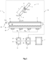
- THE figures 1 And 2 are schematic and partial views, respectively in section and in exploded view, of a system 1 for recording the trace of a utensil 3 according to one embodiment.
- the utensil 3 is a stylus whose tip 4 is intended to come into contact with the writing surface 2.
- the tactile matrix sensor 20 is a resistive pressure matrix sensor, which is then adapted, in addition to detecting the contact of the tip 4 on the writing surface 2, to measure the pressing force (also called pressure force).
- the writing surface 2 may be the surface of a protective layer of the touch matrix sensor 20 described in detail below. It may also be the surface of an added element arranged on a support surface of the touch matrix sensor 20, this element being adapted to transmit the pressure force exerted by the tip 4 of the stylus 3 to the touch matrix sensor 20. Such an element may be, for example, one or more sheets of paper.
- a direct three-dimensional orthogonal reference frame OXYZ where the X and Y axes form a plane parallel to the writing surface 2, and where the Z axis is oriented towards the utensil 3.
- the origin O is located at the edge of a tracking zone Zs of the magnetic object 6, but it can be located elsewhere in the tracking zone Zs, for example at the edge of the writing surface 2.
- the utensil 3 is provided with a magnetic object 6, here a permanent magnet, secured here without any degree of freedom to the rigid structure 5 of the stylus 3.
- the magnetic object 6 comprises a material having a magnetization, for example remanent, for which a magnetic moment m is defined. It can be a cylindrical permanent magnet, for example annular, as illustrated in the document WO2014/053526 , or even an electromagnet. It may also be a transponder adapted to re-emit a magnetic field emitted by a network of magnetic generators. However, in this example, the magnetic object 6 is a permanent magnet. In this example, the magnetic object 6 is distinct from the tip 4 and is distant from it by a non-zero distance L. Alternatively, it may be confused with the tip 4.
- the magnetic material is preferably ferrimagnetic or ferromagnetic. It has a non-zero spontaneous magnetic moment even in the absence of an external magnetic field. It may have a coercive magnetic field greater than 100 Am -1 or 500 Am -1 and the intensity of the magnetic moment is preferably greater than 0.01 Am 2 or even 0.1 Am 2 , for example equal to approximately 0.2 Am 2 . It is considered that the magnetic object 6 can be approximated by a magnetic dipole, but other models can be used.
- the magnetic axis of the magnetic object 6 is defined as being the axis collinear with the magnetic moment m of the magnetic object 6. Preferably, the magnetic axis is directed towards the tip of the utensil.
- the magnet 6 can be arranged at a non-zero distance L from the tip 4 of the stylus 3.
- This distance L is known and does not vary over time. It is defined in a digital model representative of the utensil 3 used, this model being recorded in a memory 13 of the location device 10. Also, knowledge of the position and orientation of the magnet 6 in the OXYZ frame of reference makes it possible to deduce the position P p of the tip 4 of the stylus 3. In the case where the magnet 6 and the tip 4 are the same, it is not necessary to determine the orientation of the magnetic moment m of the magnet 6.
- the stylus 3 is intended to be manipulated by the user in a tracking zone Zs. Initially, the stylus 3 is not in contact with the writing surface 2, and is distant therefrom by a non-zero value d which varies over time. Then the user brings the stylus 3 so that there is contact of the tip 4 on the writing surface 2. The distance d is then zero and the tactile matrix sensor 20 detects the contact and advantageously the pressure force exerted by the tip 4. Then, the user moves the tip 4 of the stylus 3 on the writing surface 2. The successive positions of the tip 4 in contact with the writing surface 2 form the trace determined by the trace recording system 1.
- the trace recording system 1 also comprises a location device 10, adapted to determine a state vector X a representative of the position of the magnet 6 in the OXYZ frame of reference, and possibly of its orientation, then to determine at least one estimated reference position ⁇ p
- the location device 10 determines, at different successive measurement times, an estimated reference position ⁇ p
- c is preferably a projection along the Z axis of the position P p of the tip 4 on the XY plane of the writing surface 2. It is said to be estimated insofar as it is determined by the location device 10 and not by the touch matrix sensor 20.
- the magnet 6 By locating the magnet 6, we mean determining the position of the magnet 6 in the tracking zone Zs in the form of a state vector X a and possibly its orientation.
- the position P a of the magnet 6 corresponds here to the coordinates of the geometric center of the magnet 6, i.e. to the unweighted barycenter of all the points of the magnet 6.
- the magnetic moment m of the magnet 6 is a vector whose the components are (m x , m y , m z ) in the real frame OXYZ. Its norm, also called intensity or amplitude, is noted ⁇ m ⁇ or m.
- the magnet 6 is intended to move in the tracking zone Zs.
- This is a space in which the signal-to-noise ratio SNR (for Signal to Noise Ratio, in English) of at least one of the magnetometers of the location device 10 is greater than or equal to a predefined threshold value.
- the tracking zone Zs may be a space in which the signal, i.e. the standard or at least one component of the magnetic field generated by the magnet 6 and measured by the corresponding magnetometer, is greater than or equal to, for example, 20 times the noise.
- the noise associated with each magnetometer may be equal to approximately 0.2 ⁇ T.
- the tracking zone Zs corresponds to a zone of space in which the magnetic field generated by the magnet 6 and measured by at least one of the magnetometers M i is greater than or equal to approximately 6 ⁇ T, which corresponds to a distance d max equal to approximately 20cm along the director axis passing through the magnetometer M i considered. More simply, the tracking zone Zs can be defined as a space in which each point is at a distance less than or equal to a maximum distance d max along the director axis passing through the closest magnetometer M i , this being for example equal to 20cm, or even 10cm, or even 5cm.
- the location device 10 is capable of measuring the ambient magnetic field, one of the contributions of which is the magnetic field generated by the magnet 6, at different measurement times, during a tracking duration T, in the OXYZ frame of reference, and then of estimating the position of the magnet 6, and possibly its orientation, on the basis of the measurements of the magnetometers M i .
- the network of magnetometers M i comprises a network of magnetometers M i secured here without degree of freedom to a rear face of the tactile matrix sensor 20.
- the number of magnetometers M i may be, for example greater than or equal to 2, preferably greater than or equal to 16, for example equal to approximately 25, in particular when they are triaxial magnetometers.
- the network of magnetometers M i however comprises at least three measurement axes distant from each other and not parallel two by two.
- the magnetometers M i may be aligned rows and columns, or may be mutually positioned in a substantially random manner.
- the positions of the magnetometers M i are known. For example, they may be between 1 cm and 10 cm, for example 5 cm.
- the magnetometers M i each have at least one measuring axis, for example three axes, denoted x i , y i , z i . Each magnetometer therefore measures the amplitude and the direction of the ambient magnetic field B i , a contribution of which is generated by the magnet 6. More precisely, each magnetometer M i measures the norm of the orthogonal projection of the ambient magnetic field B i along the axes x i , y i , z i of the magnetometer.
- a calibration parameter of the magnetometers M i can be the noise associated with the magnetometers, here of the order of 0.2 ⁇ T.
- ambient magnetic field B we mean the magnetic field not disturbed by any magnetic element, formed in particular by a terrestrial contribution B terr of the order of 50 ⁇ T, to which is added the magnetic field B a generated by the magnet 6.
- Other magnetic contributions can be added, such as a contribution associated with the noise of the sensors and a contribution linked to an offset error, which are neglected here.
- the location device 10 further comprises a calculation unit 11 capable of determining from the measurements of the magnetometers M i the position of the magnet 6 in the OXYZ frame of reference and possibly its orientation, the position and where appropriate the orientation defining a state vector X a .
- the calculation unit 11 is capable of determining the position P p of the tip 4 of the stylus 3 in the OXYZ frame of reference.
- the calculation unit 11 is also adapted to determine an estimated reference position ⁇ p
- the calculation unit 11 comprises the coordinates of the writing surface 2 in the OXYZ frame of reference. Thus, knowing the position of the tip P p and the coordinates of the writing surface 2 in the OXYZ frame, it is able to determine the estimated reference position ⁇ p
- each magnetometer M i is electrically connected to the calculation unit 11 by an information transmission bus (not shown).
- the calculation unit 11 comprises a programmable processor 12 capable of executing instructions recorded on an information recording medium. It further comprises a memory 13 containing the instructions necessary for implementing the location of the magnet 6, as well as the digital model of the utensil 3 used, making it possible to provide the position P p of the tip 4 of the stylus 3 in the OXYZ frame of reference from the state vector X a .
- the memory 13 is also adapted to store the information calculated at each measurement instant.
- the computing unit 11 implements a mathematical model associating the position of the magnet 6 in the OXYZ frame, as well as, in this example, the orientation and intensity of its magnetic moment m, with the measurements of the magnetometers M i .
- This mathematical model is constructed from the equations of electromagnetism, in particular magnetostatics, and is parameterized in particular by the positions and orientations of the magnetometers in the OXYZ frame.
- this model is non-linear.
- the computing unit 11 implements an algorithm for estimating its solution such as, for example, Bayesian filtering (e.g. extended Kalman filter) or optimization, or even any other algorithm of the same type.
- the distance between the magnet 6 and each magnetometer M i is greater than 2, or even 3 times the largest dimension of the magnet 6. This dimension may be less than 20 cm, or even less than 10 cm, or even 5 cm.
- the magnet 6 may be modeled by a dipole model, among other things, depending in particular on the distance between the magnet 6 and each magnetometer M i of the network.
- the trace recording system 1 comprises a touch matrix sensor 20, here a pressure matrix sensor. It is adapted to detect the contact of the tip 4 of the stylus 3 on the writing surface 2 from here the measurement of the intensity of the pressure force exerted on this writing surface 2.
- the pressure matrix sensor comprises a pressure matrix, formed of a plurality of pixels Px i sensitive to the pressure exerted on its surface.
- the pressure matrix is in this example of the resistive type.
- Such a sensor is also called a resistive force sensor ( Force-Sensing Resistor, in English).
- a film 23 made of a piezoresistive material, that is to say of a material whose local electrical resistance varies according to the mechanical stress exerted, for example of a conductive polymer.
- the sensitive material of the film can be continuous in the XY plane or can be pixelated.
- Conductive tracks 21, 22 are formed in lines on one face of the film 23 and in columns on the opposite face.
- the pixels Px i are formed by the intersection, in top view, between the lines and the columns of the conductive tracks 21, 22.
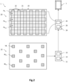
- the pixels Px i can be adjacent to each other, or even be spaced from each other (as illustrated in the fig.2 ).
- the pressure matrix sensor 20 comprises a number N of pixels Px i , for example equal to approximately 2500.
- the conductive tracks 21, 22 may have a width of a few millimeters, for example 2.5 mm, so that a pixel here has a surface area of 2.5 ⁇ 2.5 mm 2 .
- the pixels Px i are distinct and are spaced apart in the XY plane from each other, for example by a distance of approximately 1 mm.
- the diameter of the tip 4 of the stylus 3 in contact with the writing surface 2 can here be of the order of a millimeter, for example between approximately 1mm and 3mm.
- the pressure matrix sensor 20 comprises a processing unit 24, comprising a microcontroller 25 ensuring the control and reading of the different pixels of the pressure matrix, and a calculation unit 26 adapted to detect the contact of the tip 4 and to determine the intensity of the pressure force exerted, on the basis of the electrical response signals emitted by the pixels.
- the microcontroller 25 is thus adapted to transmit an electrical control signal to each of the pixels, and to receive an electrical response signal, the latter being representative of a possible contact of the tip 4 of the stylus 3 on the writing surface 2, and furthermore, here, of the intensity of the pressure force exerted by the stylus 3.
- the processing unit 24 comprises the coordinates of the N pixels Px i in the OXYZ reference frame.
- M is preferably greater than or equal to 2.
- the calculation unit 26 from the received electrical response signals, detects whether or not there is contact of the tip 4 on the writing surface 2. For this, the electrical signal emitted by each pixel has an intensity which, when it is greater than a predetermined threshold, corresponds to the contact of the tip 4 on the writing surface 2. The intensity of the pressure force exerted by the tip 4 is dependent on the intensity of the electrical signals emitted by one or more pixels.
- the processing unit 24 then records the successive estimated reference positions ⁇ p
- the intensity of the pressure force exerted makes it possible to provide an additional characteristic of the trace of the utensil 3, and can be used to vary for example the width of the trace of the utensil 3.
- the processing unit 24 can be connected to a graphical interface 7, to display for example the trace detected by the system.
- the processing unit 24 can thus comprise a microcontroller 25 for controlling the electrical power supply of the pixels, associated with analog-digital converters CAN, and its calculation unit 26 comprises at least one processor and at least one memory containing the instructions necessary for implementing the detection of the contact of the tip 4 and the measurement of the force of pressure, and to store the information calculated at each measurement moment, and here converters.
- the processor and the memory of the calculation unit 26 may or may not be common with those of the microcontroller 25.
- the processing unit 24 of the touch matrix sensor 20 is connected to the calculation unit 11 of the location device 10, and receives from the latter the successive estimated reference positions ⁇ p
- the touch matrix sensor 20 receives this data only when the position P p,z of the tip 4 along the Z axis is less than or equal to a predetermined threshold value P p,z,th .
- the touch matrix sensor 20 can be inactive, that is to say not electrically powered completely or in part, so as to limit the electrical consumption of the trace recording system 1.
- the processing unit 24 When the position P p,z is less than or equal to the threshold value P p,z,th , the processing unit 24 is activated (electrically powered), receives the value of the estimated reference position ⁇ p
- the total number N of pixels may be equal to approximately 2500
- the number M of pixels of said set S px may be equal to approximately 25, for example a 5 ⁇ 5 pixel square.
- the processing unit 24 measures only the pixels of said set S px and not all the pixels of the matrix.
- the electrical control signals are therefore transmitted only to the M pixels while the other pixels are not electrically powered. Then, the electrical response signals are received by the processing unit 24.
- the pixel control/reading latency is greatly reduced, since here it is a question of reading 25 pixels for each measurement instant, and not 2500 pixels. Consequently, the electrical consumption is also greatly reduced.
- the processing unit 24 is finally adapted to determine the trace made by the stylus 3 from the successive estimated reference positions ⁇ p
- the trace can be formed by all of the successive estimated positions ⁇ p
- the system 1 for recording the trace due to the combination of the location device 10 of the magnetic object 6 and the tactile matrix sensor 20, has several advantages. It is thus possible to use a large number of commercial utensils, as long as it allows the magnetic object 6 to be fixed there, such as a magnet.
- the utensil 3 may also be provided with only one magnet 6 to be located. It is therefore not necessary for it to be provided with several magnets, even if it is possible to provide several magnets secured to the utensil. This avoids the need to use a dedicated and complex utensil 3, as in the document EP2811383 . It is also not necessary to integrate a pressure sensor into the utensil.
- the contact of the tip 4 is detected precisely by the touch matrix sensor 20, and the position of the tip 4 on the writing surface 2 is determined with high resolution by the localization device 10.
- the position of the tip 4 is thus not impacted by the potentially low resolution of conventional touch matrix sensors, which depends on the dimensions and arrangement of the conductive tracks 21, 22.
- c on the writing surface 2 is not disturbed by possible parasitic contacts, such as the contact of the finger or that of the palm of the user's hand on the writing surface 2.
- the trace recording system 1 has a particularly reduced latency related to the control/reading of the pixel matrix, since only the M selected pixels of the set S px are activated by the microcontroller 25, and not the N pixels of the matrix.
- the control/reading frequency can then be particularly high. Consequently, the electrical consumption of the trace recording system 1 is reduced.
- the tactile matrix sensor 20 it is advantageous for the tactile matrix sensor 20 to remain at least partly inactive during the tracking of the magnetic object 6 by the location device 10, in particular when the position P p,z of the tip 4 along the Z axis is greater than the threshold value P p,z,th .
- a touch matrix sensor 20 whose microcontroller 25 and electrical connections are simple and conventional. This avoids having to use a microcontroller 25 and special connections linked to the need to activate the lines and/or columns either individually and sequentially, or collectively, as described in the document WO2013/057412 .
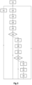
- FIG. 3 is a flowchart illustrating a method for recording the trace of the utensil 3 according to one embodiment.
- the trace recording system 1 is identical to that described with reference to fig. 1 And 2 . It commands the graphical interface 7 to display the trace thus recorded.
- a digital model of the stylus 3 is recorded in the memory 13 of the calculation unit 11 of the location device 10.
- this digital model makes it possible to deduce the position P p of the tip 4 in the OXYZ frame from the state vector X a of the magnet 6.
- This step 11 may also include a phase of recording the coordinates in the OXYZ frame of the writing surface 2, as well as a phase of recording the coordinates in the OXYZ frame of the N pixels Px i of the touch matrix sensor 20.
- the user manipulates the stylus 3 in the tracking zone Zs, that is to say, he modifies its position and possibly its orientation in the OXYZ reference frame.
- the tip 4 of the stylus 3 is not in contact with the writing surface 2 and has a position P p,z along the Z axis greater than the threshold value P p,z,th .
- the tip 4 has a position P p,z less than or equal to the threshold value P p,z,th but is still not in contact with the writing surface 2.
- Steps 22 to 33 are performed iteratively at a measurement time t n , with time being discretized at a given sampling frequency, for example 140 Hz. Each iteration of rank n is associated with a measurement time t n , also called the current time.
- the magnetometers measure the ambient magnetic field at the current time, and in particular the contribution of the ambient magnetic field generated by the magnet 6 secured to the stylus 3.
- the calculation unit 11 receives the measurements of the ambient magnetic field, deduces therefrom the contribution of the magnetic field generated by the magnet 6, and determines the state vector X a (t n ) associated with the magnet 6 at the current time t n in the OXYZ frame.
- the state vector X a (t n ) comprises the position of the magnet 6 in the OXYZ frame, and also, in this example, its orientation.
- This estimation of the state vector can be carried out using a position estimation algorithm and the orientation of the Bayesian type magnet 6, for example an extended Kalman filter, or using an optimization method (gradient descent, etc.), or using any other algorithm of the same type.
- An example of estimating a state vector associated with a magnet 6 is notably described in the application WO2018/219891 .
- the calculation unit 11 determines the position P p (t n ) of the tip 4 of the stylus 3, from the state vector X a (t n ) and the digital model of the stylus 3.
- the position P p (t n ) of the tip 4 comprises the component P p,z (t n ) along the Z axis and the component P p,xy (t n ) in the XY plane parallel to the writing surface 2.
- the position P p (t n ) of the tip 4 is identical to the position P a (t n ).
- the calculation unit 11 determines the estimated reference position ⁇ p
- c may be equal to the projection along the Z axis of the position P p,xy (t n ) of the tip 4 in the XY plane, in which case there is equality between ⁇ p
- a step 26 the value of the position P p,z (t n ) of the tip 4 along the Z axis is compared to the predefined threshold value P p,z,th .
- the location device 10 continues to measure the magnetic field (step 22 and following).
- the touch matrix sensor 20 advantageously remains deactivated, that is to say that it is not electrically powered, so as to limit the electrical consumption of the trace recording system 1. If the location device 10 is directly connected to the graphical interface 7, the tip 4 can be represented and displayed on the graphical interface 7, without a trace being displayed.
- the method continues with step 27.
- a step 27 the touch matrix sensor 20 is activated (if applicable), and the value of the estimated reference position ⁇ p
- the latter determines a set S px (t n ) of pixels of the pressure matrix which at least partly surround the estimated reference position ⁇ p
- the processing unit 24 determines a pixel selection zone Z px (t n ) centered on the estimated reference position ⁇ p
- the Figures 4A and 4B illustrate system 1 of trace recording at two distinct measurement times, and show the area Z px (t n ) centered on the estimated reference position ⁇ p
- the set S px (t n ) includes the pixels whose surface is at least partly located inside this pixel selection area Z px (t n ). This set S px (t n ) is redefined at each measurement time t n .
- the touch matrix sensor 20 may have been initialized by measuring the “background noise” associated with the pixel matrix in the absence of any contact (tip of the stylus, finger, palm, etc.) on the writing surface 2. This initial measurement is then systematically subtracted from the measurements of the electrical response signals of the pixels of the set S px (t n ), thus making it possible to eliminate any temporal drifts and/or offset errors.
- the microcontroller 25 of the processing unit 24 activates only the M pixels of the set S px (t n ), and keeps the other non-selected pixels (i.e. not electrically powered) inactive. It therefore transmits an electrical control signal to the pixels of the set S px (t n ) and receives their electrical response signals.
- the processing unit 24 determines the value of a parameter ⁇ (t n ) representative of the contact of the tip 4 on the writing surface 2.
- This parameter may be the intensity of the electrical response signal of at least one of the pixels of the set S px (t n ), or even the average intensity, weighted or not, of the electrical response signals of the pixels of the set S px (t n ). It may be the electrical resistance of at least one of the pixels of the set S px (t n ), or any other equivalent parameter.
- the processing unit 24 compares the value of the parameter ⁇ (t n ) with a predefined threshold value ⁇ th and detects the contact of the tip 4 on the writing surface 2 as being effective when the value of the parameter ⁇ (t n ) is greater than or equal to the threshold value ⁇ th .
- the threshold value ⁇ th makes it possible to filter out fluctuations related to measurement noise.
- the processing unit 24 records the estimated reference position ⁇ p
- c (t n ) recorded by the processing unit 24 form or participate in forming the record of the trace made by the stylus 3.
- the position of the tip 4 in contact with the writing surface 2, as recorded by the processing unit 24, may depend both on the estimated reference position ⁇ p
- c (t n ) may correspond to the position of the centroid (weighted barycenter) of the pressure forces exerted by the tip 4 on the writing surface 2, and measured by the pixels of the set S px (t n ).
- the position of the tip 4 recorded by the processing unit 24 may be the average, weighted or not, of the positions ⁇ p
- a step 32 when the touch matrix sensor 20 is adapted to measure the pressure force, that is to say that it comprises a pressure matrix, the processing unit 24 measures the pressure force applied by the tip 4 on the writing surface 2.
- the pressure force is determined from the intensity of the electrical response signals emitted by the pixels of the set S px (t n ).
- the pressure force, at the current time t n makes it possible for example to modify a characteristic of the trace, for example the width of the line displayed on the graphical interface 7.
- the processing unit 24 constructs the trace from the successive positions of the tip 4 recorded, and here taking into account the pressure force applied by the tip 4 on the writing surface 2. It then controls the display of the trace thus recorded on the graphical interface 7.
- Steps 22 to 33 are repeated at the defined sampling frequency, which may or may not be constant over time, and which may in particular depend on the speed of movement of the magnet 6 or of the tip 4, calculated by the locating device 10 from the state vector X a (t n ).
- the sampling frequency associated with the locating of the magnet 6 e.g. 140 Hz
- the sampling frequency associated with the locating of the magnet 6 may be identical to or different from the frequency of control/reading of the pixels of the set S px (t n ).
- FIGS. 4A and 4B are perspective views of the utensil 3 manipulated by a user above the writing surface 2 of the touch matrix sensor 20, for two different moments.
- tip 4 has a position P p,z (t n ) of tip 4 along the Z axis lower than the threshold value P p,z,th , so that the matrix sensor touch 20 is activated and the estimated reference position ⁇ p
- the stylus 3 is positioned at the edge of the writing surface 2.
- the selection area Z px (t n ) then extends across the writing surface 2 and outside it.
- a pixel is entirely located in the selection area Z px (t n ), and is surrounded by 5 adjacent pixels located partially in the selection area Z px (t n ).
- the set S px (t n ) comprises the 6 pixels located at least partly in the selection area Z px (t n ).
- the selected pixels thus at least partly surround the estimated reference position ⁇ p
- the stylus 3 is positioned in the center of the writing surface 2.
- the selection area Z px (t n ) then extends entirely within the writing surface 2.
- a single pixel is entirely located in the selection area Z px (t n ), and is surrounded by 8 adjacent pixels located partially in the selection area.
- the set S px comprises the 9 pixels located at least partly in the selection area Z px (t n ). The selected pixels thus at least partly surround the estimated reference position ⁇ p
- the selection zone Z px (t n ) may have other shapes.
- it may have an elongated shape, the major axis then being oriented in the direction of movement of the tip 4, which is determined by the location device 10 from the state vector X a (t n ).
- the dimension of the major axis may also depend on the speed of movement of the tip or the magnet, this speed of movement being determined by the calculation unit 11 from the state vector X a estimated for several measurement times, and being transmitted to the processing unit 24.
- the shape and/or size of the selection zone Z px (t n ) may depend on the type of utensil 3 used, and possibly on the characteristics of the tip 4.
- the trace recording system 1 can comprise several utensils 3 each equipped with at least one magnetic object 6, intended to come into contact with the same writing surface 2.
- the location device 10 can thus determine a state vector for each of the magnetic objects 6, and the tactile matrix sensor 20 can determine the contact of the tip 4 of each of the utensils 3.
Landscapes
- Engineering & Computer Science (AREA)
- Theoretical Computer Science (AREA)
- General Engineering & Computer Science (AREA)
- Physics & Mathematics (AREA)
- General Physics & Mathematics (AREA)
- Human Computer Interaction (AREA)
- Electromagnetism (AREA)
- Measurement Of Length, Angles, Or The Like Using Electric Or Magnetic Means (AREA)
- User Interface Of Digital Computer (AREA)
Claims (11)
- System (1) zum Erfassen einer Spur, die auf einer Schreibfläche (2) ausgeführt wird, enthaltend:∘ ein Gerät (3), das dazu vorgesehen ist, durch einen Benutzer gehandhabt zu werden, und mit einem magnetischen Gegenstand (6) ausgestattet ist, und eine Spitze (4) enthaltend, die dazu vorgesehen ist, mit der Schreibfläche (2) in Kontakt zu kommen, um die zu erfassende Spur zu bilden;∘ eine Ortungsvorrichtung (10), enthaltend:• ein Netzwerk von Magnetometern (Mi), die mit der Schreibfläche (2) fest verbunden sind, und angepasst sind, um das Magnetfeld zu messen, das durch den magnetischen Gegenstand (6) zu verschiedenen aufeinanderfolgenden Messzeitpunkten tn emittiert wird,• eine elektronische Recheneinheit (11), die angepasst ist, um einen Zustandsvektor Xa zu bestimmen, der für mindestens eine Position des magnetischen Gegenstands (6) ausgehend vom gemessenen Magnetfeld repräsentativ ist, und um eine geschätzte Referenzposition Čp|c auf der Schreibfläche (2) ausgehend vom Zustandsvektor Xa zu bestimmen,∘ dadurch gekennzeichnet, dass es einen taktilen Matrixsensor (20), enthält, enthaltend:• eine Matrix von N unterschiedlichen Pixeln (Pxi), die mit der Schreibfläche (2) fest verbunden sind, und jeweils angepasst sind, um ein elektrisches Antwortsignal zu liefern, das für einen Kontakt der Spitze (4) auf der Schreibfläche (2) repräsentativ ist;• eine elektronische Verarbeitungseinheit (24), die mit der elektronischen Recheneinheit (11) verbunden ist, und angepasst ist, um eine Anordnung Spx von M Pixeln zu bestimmen, mit M kleiner als N, die die geschätzte Referenzposition Čp|c mindestens teilweise umgibt, um ein elektrisches Steuersignal an die M Pixel der Anordnung Spx zu übertragen und ihre elektrischen Antwortsignale zu empfangen; und um den Kontakt der Spitze (4) auf der Schreibfläche (2) ausgehend von den elektrischen Antwortsignalen, die von der Anordnung Spx der M Pixel ausgegangen sind, zu detektieren, und, wenn der Kontakt detektiert wurde, um die aufeinanderfolgenden Positionen der Spitze (4) aufzuzeichnen, um die Erfassung der Spur in Abhängigkeit von mindestens den geschätzten aufeinanderfolgenden Referenzpositionen Čp|c zu bilden.
- System (1) nach Anspruch 1, wobei die Ortungsvorrichtung (10) angepasst ist, um eine Position Pp,z der Spitze (4) entlang einer Achse orthogonal zur Schreibfläche (2) ausgehend vom Zustandsvektor Xa zu bestimmen, um die bestimmte Position Pp,z mit einem vordefinierten Schwellenwert Pp,z,th zu vergleichen, und um die geschätzte Referenzposition Čp|c an den taktilen Matrixsensor (20) zu übertragen, wenn die Position Pp,z kleiner oder gleich dem vordefinierten Schwellenwert Pp,z,th ist.
- System (1) nach Anspruch 1 oder 2, wobei die Ortungsvorrichtung (10) angepasst ist, um die Position Pp,z der Spitze (4) entlang der Achse orthogonal zur Schreibfläche (2) ausgehend vom Zustandsvektor Xa zu bestimmen, um die bestimmte Position Pp,z mit einem vordefinierten Schwellenwert Pp,z,th zu vergleichen und den taktilen Matrixsensor (20) zu aktivieren, wenn die Position Pp,z kleiner oder gleich dem vordefinierten Schwellenwert Pp,z,th ist, wobei im umgekehrten Fall der taktile Matrixsensor (20) nicht elektrisch versorgt wird.
- System (1) nach einem der Ansprüche 1 bis 3, wobei die geschätzte Referenzposition Čp|c durch Projektion entlang der Achse orthogonal zur Schreibfläche (2) der Position Pp,xy der Spitze (4) in einer Ebene parallel zur Schreibfläche (2) bestimmt wird.
- System (1) nach einem der Ansprüche 1 bis 4, wobei die Ortungsvorrichtung (10) angepasst ist, um eine Geschwindigkeit der Bewegung des magnetischen Gegenstands (6) ausgehend vom bestimmten Zustandsvektor Xa für mehrere Messzeitpunkte zu berechnen, und um die Geschwindigkeit der Bewegung an die Verarbeitungseinheit (24) zu übertragen, wobei diese angepasst ist, um die Anordnung Spx von M Pixeln mit einer länglichen Kontur entlang einer Hauptachse zu definieren, wobei die Hauptachse parallel zur Achse der Geschwindigkeit der Bewegung ist.
- System (1) nach Anspruch 5, wobei die Hauptachse eine Länge aufweist, die von der Norm der Geschwindigkeit der Bewegung abhängt.
- System (1) nach einem der Ansprüche 1 bis 6, wobei der taktile Matrixsensor (20) ein Druck-Matrixsensor ist, der angepasst ist, um eine Druckkraft zu bestimmen, die von der Spitze (4) auf die Schreibfläche (2) ausgeübt wird.
- System (1) nach Anspruch 7, wobei der taktile Matrixsensor (20) angepasst ist, um eine Position Čp|c des Punkts des Kontakts der Spitze (4) auf der Schreibfläche (2) zu bestimmen, wobei die Position der Spitze (4), die aufgezeichnet wird, um die Spur zu bilden, von der geschätzten Referenzposition Čp|c und der Position Čp|c des Punkts des Kontakts der Spitze (4) abhängt.
- System (1) nach einem der Ansprüche 1 bis 8, wobei der Zustandsvektor Xa durch einen bayesschen Schätzungsalgorithmus oder durch eine Optimierungsmethode bestimmt wird.
- Verfahren zum Erfassen einer Spur der Spitze (4) eines Geräts (3) auf einer Schreibfläche (2) mittels des Systems nach einem der vorhergehenden Ansprüche, die folgenden Schritte enthaltend:∘ Handhabung des Geräts (3) durch einen Benutzer, wobei dieses zunächst nicht in Kontakt mit der Schreibfläche (2) ist und dann in Kontakt mit der Schreibfläche (2) kommt;∘ Messung, durch das Netzwerk von Magnetometern (Mi), des Magnetfelds, das durch den magnetischen Gegenstand (6) zu verschiedenen aufeinanderfolgenden Messzeitpunkten tn emittiert wird;∘ Bestimmung, durch die elektronische Recheneinheit (11), des Zustandsvektors Xa(tn) des magnetischen Gegenstands (6) ausgehend von den Messungen des gemessenen Magnetfelds;∘ Bestimmung, durch die elektronische Recheneinheit (11), der geschätzten Referenzposition Čp|c(tn) auf der Schreibfläche (2) ausgehend vom bestimmten Zustandsvektor Xa(tn);∘ dadurch gekennzeichnet, dass es ferner die folgenden Schritte enthält:∘ Bestimmung, durch die elektronische Verarbeitungseinheit (24), der Anordnung Spx(tn) von M Pixeln (Pxi), die die geschätzte Referenzposition Čp|c(tn) mindestens teilweise umgibt;∘ Übertragung, durch die elektronische Verarbeitungseinheit (24), des elektrischen Steuersignals an die Pixel der Anordnung Spx(tn), und Empfang der elektrischen Antwortsignale;∘ Detektion, durch die elektronische Verarbeitungseinheit (24), des Kontakts der Spitze (4) auf der Schreibfläche (2) ausgehend von den elektrischen Antwortsignalen, die von der Anordnung Spx der M Pixel ausgegangen sind, und, wenn der Kontakt detektiert wurde, Aufzeichnung der aufeinanderfolgenden Positionen der Spitze (4), um die Erfassung der Spur in Abhängigkeit von mindestens den geschätzten aufeinanderfolgenden Referenzpositionen Čp|c(tn) zu bilden.
- Informationsaufzeichnungsmedium, das Anweisungen zum Ausführen eines Verfahrens zum Erfassen einer Spur nach Anspruch 10 enthält, wenn diese Anweisungen von einer Recheneinheit ausgeführt werden.
Applications Claiming Priority (2)
| Application Number | Priority Date | Filing Date | Title |
|---|---|---|---|
| FR1911036A FR3101717B1 (fr) | 2019-10-04 | 2019-10-04 | système de relevé d’une trace effectuee par un ustensile sur une surface d’écriture |
| PCT/EP2020/077402 WO2021064041A1 (fr) | 2019-10-04 | 2020-09-30 | Systeme de releve d'une trace effectuee par un ustensile sur une surface d'ecriture |
Publications (2)
| Publication Number | Publication Date |
|---|---|
| EP4038482A1 EP4038482A1 (de) | 2022-08-10 |
| EP4038482B1 true EP4038482B1 (de) | 2024-12-04 |
Family
ID=69375477
Family Applications (1)
| Application Number | Title | Priority Date | Filing Date |
|---|---|---|---|
| EP20780215.8A Active EP4038482B1 (de) | 2019-10-04 | 2020-09-30 | System zur erfassung eines von einem gerät auf einer schreiboberfläche zurückgelegten weges, und entsprechendes verfahren und informations-aufzeichnungsmedium |
Country Status (6)
| Country | Link |
|---|---|
| US (1) | US11782527B2 (de) |
| EP (1) | EP4038482B1 (de) |
| JP (1) | JP7642626B2 (de) |
| CN (1) | CN115053206B (de) |
| FR (1) | FR3101717B1 (de) |
| WO (1) | WO2021064041A1 (de) |
Families Citing this family (3)
| Publication number | Priority date | Publication date | Assignee | Title |
|---|---|---|---|---|
| FR3114413B1 (fr) * | 2020-09-21 | 2023-06-09 | Advanced Magnetic Interaction Ami | Procédé et dispositif de suivi d’une extrémite d’un ustensile comportant une recalibration d’une distance entre l’extrémité et un objet magnétique solidaire de l’ustensile |
| EP4390633B1 (de) * | 2022-12-22 | 2026-02-04 | Advanced Magnetic Interaction, AMI | Elektronische vorrichtung mit magnetometern |
| EP4390635A1 (de) * | 2022-12-22 | 2024-06-26 | Advanced Magnetic Interaction, AMI | Peripheriegerät mit magnetometern |
Family Cites Families (17)
| Publication number | Priority date | Publication date | Assignee | Title |
|---|---|---|---|---|
| JP2006092187A (ja) | 2004-09-22 | 2006-04-06 | Hitachi Medical Corp | 携帯情報端末装置 |
| US20130009907A1 (en) * | 2009-07-31 | 2013-01-10 | Rosenberg Ilya D | Magnetic Stylus |
| US9195351B1 (en) | 2011-09-28 | 2015-11-24 | Amazon Technologies, Inc. | Capacitive stylus |
| FR2981765B1 (fr) | 2011-10-20 | 2013-12-27 | Stantum | Procede d'acquisition de donnees d'un capteur tactile matriciel, notamment pour un ecran tactile |
| KR101898979B1 (ko) | 2012-02-16 | 2018-09-17 | 삼성디스플레이 주식회사 | 터치 패널의 구동 방법, 터치 패널 및 디스플레이 장치 |
| FR2988862B1 (fr) * | 2012-03-29 | 2014-03-28 | Commissariat Energie Atomique | Procede et dispositif de localisation d'un objet magnetique |
| FR2988872B1 (fr) * | 2012-03-29 | 2014-03-28 | Commissariat Energie Atomique | Ecran avec localisation d'objet magnetique |
| EP2662756A1 (de) | 2012-05-11 | 2013-11-13 | BlackBerry Limited | Handflächeneingabezurückweisung für Berührungsbilde |
| FR2996653B1 (fr) | 2012-10-05 | 2015-01-02 | Commissariat Energie Atomique | Anneau magnetique apte a etre fixe de facon amovible sur un crayon ou un effaceur |
| FR3006778B1 (fr) | 2013-06-07 | 2015-07-03 | Commissariat Energie Atomique | Systeme et procede de releve de la trace dessinee sur un support d'ecriture |
| US20160018945A1 (en) | 2014-07-17 | 2016-01-21 | Prime Circa, Inc. | Heuristic palm detection |
| KR101484916B1 (ko) * | 2014-08-25 | 2015-01-22 | 주식회사 트레이스 | 위치 확인의 정확도를 높인 디지타이저 |
| FR3029656B1 (fr) * | 2014-12-09 | 2017-01-13 | ISKn | Procede de detection continue d'un etat de contact ou de non contact entre une pointe d'un ustensile et un support d'ecriture d'epaisseur variable, et systeme associe |
| FR3029642B1 (fr) * | 2014-12-09 | 2017-12-08 | ISKn | Procede de localisation d'au moins un objet magnetique mobile, et systeme associe |
| US10025440B2 (en) | 2016-07-13 | 2018-07-17 | Stmicroelectronics Asia Pacific Pte Ltd | Correlated data acquisition among different touch sensors |
| FR3067139B1 (fr) | 2017-05-31 | 2019-09-27 | ISKn | Procede de suivi d’un aimant par un reseau de magnetometres, comportant une phase d’identification de la presence de l’aimant et d’un perturbateur magnetique |
| JP7092480B2 (ja) | 2017-09-27 | 2022-06-28 | エルジー ディスプレイ カンパニー リミテッド | センサ装置及びその制御方法 |
-
2019
- 2019-10-04 FR FR1911036A patent/FR3101717B1/fr active Active
-
2020
- 2020-09-30 CN CN202080084246.5A patent/CN115053206B/zh active Active
- 2020-09-30 US US17/765,524 patent/US11782527B2/en active Active
- 2020-09-30 WO PCT/EP2020/077402 patent/WO2021064041A1/fr not_active Ceased
- 2020-09-30 JP JP2022520720A patent/JP7642626B2/ja active Active
- 2020-09-30 EP EP20780215.8A patent/EP4038482B1/de active Active
Also Published As
| Publication number | Publication date |
|---|---|
| US11782527B2 (en) | 2023-10-10 |
| FR3101717B1 (fr) | 2021-09-10 |
| US20220397967A1 (en) | 2022-12-15 |
| FR3101717A1 (fr) | 2021-04-09 |
| JP2022550894A (ja) | 2022-12-05 |
| JP7642626B2 (ja) | 2025-03-10 |
| WO2021064041A1 (fr) | 2021-04-08 |
| EP4038482A1 (de) | 2022-08-10 |
| CN115053206A (zh) | 2022-09-13 |
| CN115053206B (zh) | 2025-05-27 |
Similar Documents
| Publication | Publication Date | Title |
|---|---|---|
| EP4038482B1 (de) | System zur erfassung eines von einem gerät auf einer schreiboberfläche zurückgelegten weges, und entsprechendes verfahren und informations-aufzeichnungsmedium | |
| EP2831641B1 (de) | Verfahren und vorrichtung zur lokalisierung eines magnetischen objekts | |
| EP3485299B1 (de) | Verfahren zur schätzung einer winkelabweichung zwischen der magnetischen achse und einer referenzachse eines magnetischen objekts | |
| EP2831705B1 (de) | Bildschirm mit magnetischer objektfindung | |
| EP2811383B1 (de) | System, Werkzeug, Gerät, Verfahren und Informationsaufzeichnungsmedium zur Aufnahme des Spurverlaufs auf einer Schreibunterlage | |
| EP3519760B1 (de) | Vorrichtung zur ortung eines aufpralls gegen eine interaktive oberfläche, entsprechende vorrichtung, verfahren und computerprogramm | |
| EP2831711B1 (de) | Verfahren zur erkennung eines kontaktpunktes zwischen einer instrumentenspitze und einer schreibunterlage | |
| EP3230771B1 (de) | Verfahren zur ortung von mindestens einem beweglichen magnetischen objekt und zugehöriges system | |
| WO2014079740A2 (fr) | Procede de reconnaissance automatique d'un objet magnetique mobile | |
| FR2956554A1 (fr) | Transducteur piezoelectrique, dispositif de transduction piezoelectrique, panneau interactif et levier de commande | |
| EP3230772B1 (de) | Verfahren zur ortung von mindestens einem beweglichen magnetischen objekt und zugehöriges system | |
| WO2013135576A1 (fr) | Procede de mesure capacitive entre un objet et un plan d'electrodes par demodulation synchrone partielle | |
| EP2769290B1 (de) | Verfahren zur erfassung der daten eines matrixberührungssensors, insbesondere für einen berührungsbildschirm | |
| EP4214598B1 (de) | Verfahren und vorrichtung zur verfolgung eines endes eines utensils mit rekalibrierung eines abstandes zwischen dem ende und einem am utensil sicher befestigten magnetischen objekt | |
| EP3008547B1 (de) | Vorrichtung zur bewegungsanalyse eines mobilen elementes und entsprechendes verfahren | |
| CH698650B1 (fr) | Dispositif électronique de commande à touches tactiles destiné à remplir une fonction de curseur. |
Legal Events
| Date | Code | Title | Description |
|---|---|---|---|
| STAA | Information on the status of an ep patent application or granted ep patent |
Free format text: STATUS: UNKNOWN |
|
| STAA | Information on the status of an ep patent application or granted ep patent |
Free format text: STATUS: THE INTERNATIONAL PUBLICATION HAS BEEN MADE |
|
| PUAI | Public reference made under article 153(3) epc to a published international application that has entered the european phase |
Free format text: ORIGINAL CODE: 0009012 |
|
| STAA | Information on the status of an ep patent application or granted ep patent |
Free format text: STATUS: REQUEST FOR EXAMINATION WAS MADE |
|
| 17P | Request for examination filed |
Effective date: 20220330 |
|
| AK | Designated contracting states |
Kind code of ref document: A1 Designated state(s): AL AT BE BG CH CY CZ DE DK EE ES FI FR GB GR HR HU IE IS IT LI LT LU LV MC MK MT NL NO PL PT RO RS SE SI SK SM TR |
|
| DAV | Request for validation of the european patent (deleted) | ||
| DAX | Request for extension of the european patent (deleted) | ||
| GRAP | Despatch of communication of intention to grant a patent |
Free format text: ORIGINAL CODE: EPIDOSNIGR1 |
|
| STAA | Information on the status of an ep patent application or granted ep patent |
Free format text: STATUS: GRANT OF PATENT IS INTENDED |
|
| INTG | Intention to grant announced |
Effective date: 20240712 |
|
| RIN1 | Information on inventor provided before grant (corrected) |
Inventor name: THOMAS, SIMON Inventor name: JAILLET-CASILLAS, MYRNA Inventor name: HAUTSON, TRISTAN Inventor name: DUPRE LA TOUR, JEAN-MARIE Inventor name: PERIS Y SABORIT, LAURE Inventor name: BRULAIS, SEBASTIEN Inventor name: VIAL, FRANCK Inventor name: ALOUI, SAIFEDDINE |
|
| GRAS | Grant fee paid |
Free format text: ORIGINAL CODE: EPIDOSNIGR3 |
|
| RAP3 | Party data changed (applicant data changed or rights of an application transferred) |
Owner name: COMMISSARIAT A L'ENERGIE ATOMIQUE ET AUX ENERGIESALTERNATIVES Owner name: ADVANCED MAGNETIC INTERACTION, AMI |
|
| GRAA | (expected) grant |
Free format text: ORIGINAL CODE: 0009210 |
|
| STAA | Information on the status of an ep patent application or granted ep patent |
Free format text: STATUS: THE PATENT HAS BEEN GRANTED |
|
| AK | Designated contracting states |
Kind code of ref document: B1 Designated state(s): AL AT BE BG CH CY CZ DE DK EE ES FI FR GB GR HR HU IE IS IT LI LT LU LV MC MK MT NL NO PL PT RO RS SE SI SK SM TR |
|
| REG | Reference to a national code |
Ref country code: CH Ref legal event code: EP |
|
| REG | Reference to a national code |
Ref country code: DE Ref legal event code: R096 Ref document number: 602020042565 Country of ref document: DE |
|
| REG | Reference to a national code |
Ref country code: IE Ref legal event code: FG4D Free format text: LANGUAGE OF EP DOCUMENT: FRENCH |
|
| REG | Reference to a national code |
Ref country code: LT Ref legal event code: MG9D |
|
| REG | Reference to a national code |
Ref country code: NL Ref legal event code: MP Effective date: 20241204 |
|
| PG25 | Lapsed in a contracting state [announced via postgrant information from national office to epo] |
Ref country code: HR Free format text: LAPSE BECAUSE OF FAILURE TO SUBMIT A TRANSLATION OF THE DESCRIPTION OR TO PAY THE FEE WITHIN THE PRESCRIBED TIME-LIMIT Effective date: 20241204 |
|
| PG25 | Lapsed in a contracting state [announced via postgrant information from national office to epo] |
Ref country code: FI Free format text: LAPSE BECAUSE OF FAILURE TO SUBMIT A TRANSLATION OF THE DESCRIPTION OR TO PAY THE FEE WITHIN THE PRESCRIBED TIME-LIMIT Effective date: 20241204 |
|
| PG25 | Lapsed in a contracting state [announced via postgrant information from national office to epo] |
Ref country code: BG Free format text: LAPSE BECAUSE OF FAILURE TO SUBMIT A TRANSLATION OF THE DESCRIPTION OR TO PAY THE FEE WITHIN THE PRESCRIBED TIME-LIMIT Effective date: 20241204 |
|
| PG25 | Lapsed in a contracting state [announced via postgrant information from national office to epo] |
Ref country code: ES Free format text: LAPSE BECAUSE OF FAILURE TO SUBMIT A TRANSLATION OF THE DESCRIPTION OR TO PAY THE FEE WITHIN THE PRESCRIBED TIME-LIMIT Effective date: 20241204 |
|
| PG25 | Lapsed in a contracting state [announced via postgrant information from national office to epo] |
Ref country code: NO Free format text: LAPSE BECAUSE OF FAILURE TO SUBMIT A TRANSLATION OF THE DESCRIPTION OR TO PAY THE FEE WITHIN THE PRESCRIBED TIME-LIMIT Effective date: 20250304 |
|
| PG25 | Lapsed in a contracting state [announced via postgrant information from national office to epo] |
Ref country code: GR Free format text: LAPSE BECAUSE OF FAILURE TO SUBMIT A TRANSLATION OF THE DESCRIPTION OR TO PAY THE FEE WITHIN THE PRESCRIBED TIME-LIMIT Effective date: 20250305 Ref country code: LV Free format text: LAPSE BECAUSE OF FAILURE TO SUBMIT A TRANSLATION OF THE DESCRIPTION OR TO PAY THE FEE WITHIN THE PRESCRIBED TIME-LIMIT Effective date: 20241204 |
|
| PG25 | Lapsed in a contracting state [announced via postgrant information from national office to epo] |
Ref country code: RS Free format text: LAPSE BECAUSE OF FAILURE TO SUBMIT A TRANSLATION OF THE DESCRIPTION OR TO PAY THE FEE WITHIN THE PRESCRIBED TIME-LIMIT Effective date: 20250304 |
|
| PG25 | Lapsed in a contracting state [announced via postgrant information from national office to epo] |
Ref country code: NL Free format text: LAPSE BECAUSE OF FAILURE TO SUBMIT A TRANSLATION OF THE DESCRIPTION OR TO PAY THE FEE WITHIN THE PRESCRIBED TIME-LIMIT Effective date: 20241204 |
|
| REG | Reference to a national code |
Ref country code: AT Ref legal event code: MK05 Ref document number: 1748838 Country of ref document: AT Kind code of ref document: T Effective date: 20241204 |
|
| PG25 | Lapsed in a contracting state [announced via postgrant information from national office to epo] |
Ref country code: SM Free format text: LAPSE BECAUSE OF FAILURE TO SUBMIT A TRANSLATION OF THE DESCRIPTION OR TO PAY THE FEE WITHIN THE PRESCRIBED TIME-LIMIT Effective date: 20241204 |
|
| PG25 | Lapsed in a contracting state [announced via postgrant information from national office to epo] |
Ref country code: PL Free format text: LAPSE BECAUSE OF FAILURE TO SUBMIT A TRANSLATION OF THE DESCRIPTION OR TO PAY THE FEE WITHIN THE PRESCRIBED TIME-LIMIT Effective date: 20241204 |
|
| PG25 | Lapsed in a contracting state [announced via postgrant information from national office to epo] |
Ref country code: IS Free format text: LAPSE BECAUSE OF FAILURE TO SUBMIT A TRANSLATION OF THE DESCRIPTION OR TO PAY THE FEE WITHIN THE PRESCRIBED TIME-LIMIT Effective date: 20250404 |
|
| PG25 | Lapsed in a contracting state [announced via postgrant information from national office to epo] |
Ref country code: PT Free format text: LAPSE BECAUSE OF FAILURE TO SUBMIT A TRANSLATION OF THE DESCRIPTION OR TO PAY THE FEE WITHIN THE PRESCRIBED TIME-LIMIT Effective date: 20250404 |
|
| PG25 | Lapsed in a contracting state [announced via postgrant information from national office to epo] |
Ref country code: EE Free format text: LAPSE BECAUSE OF FAILURE TO SUBMIT A TRANSLATION OF THE DESCRIPTION OR TO PAY THE FEE WITHIN THE PRESCRIBED TIME-LIMIT Effective date: 20241204 |
|
| PG25 | Lapsed in a contracting state [announced via postgrant information from national office to epo] |
Ref country code: AT Free format text: LAPSE BECAUSE OF FAILURE TO SUBMIT A TRANSLATION OF THE DESCRIPTION OR TO PAY THE FEE WITHIN THE PRESCRIBED TIME-LIMIT Effective date: 20241204 Ref country code: RO Free format text: LAPSE BECAUSE OF FAILURE TO SUBMIT A TRANSLATION OF THE DESCRIPTION OR TO PAY THE FEE WITHIN THE PRESCRIBED TIME-LIMIT Effective date: 20241204 |
|
| PG25 | Lapsed in a contracting state [announced via postgrant information from national office to epo] |
Ref country code: SK Free format text: LAPSE BECAUSE OF FAILURE TO SUBMIT A TRANSLATION OF THE DESCRIPTION OR TO PAY THE FEE WITHIN THE PRESCRIBED TIME-LIMIT Effective date: 20241204 |
|
| PG25 | Lapsed in a contracting state [announced via postgrant information from national office to epo] |
Ref country code: CZ Free format text: LAPSE BECAUSE OF FAILURE TO SUBMIT A TRANSLATION OF THE DESCRIPTION OR TO PAY THE FEE WITHIN THE PRESCRIBED TIME-LIMIT Effective date: 20241204 |
|
| PG25 | Lapsed in a contracting state [announced via postgrant information from national office to epo] |
Ref country code: IT Free format text: LAPSE BECAUSE OF FAILURE TO SUBMIT A TRANSLATION OF THE DESCRIPTION OR TO PAY THE FEE WITHIN THE PRESCRIBED TIME-LIMIT Effective date: 20241204 |
|
| REG | Reference to a national code |
Ref country code: DE Ref legal event code: R097 Ref document number: 602020042565 Country of ref document: DE |
|
| PG25 | Lapsed in a contracting state [announced via postgrant information from national office to epo] |
Ref country code: SE Free format text: LAPSE BECAUSE OF FAILURE TO SUBMIT A TRANSLATION OF THE DESCRIPTION OR TO PAY THE FEE WITHIN THE PRESCRIBED TIME-LIMIT Effective date: 20241204 |
|
| PG25 | Lapsed in a contracting state [announced via postgrant information from national office to epo] |
Ref country code: DK Free format text: LAPSE BECAUSE OF FAILURE TO SUBMIT A TRANSLATION OF THE DESCRIPTION OR TO PAY THE FEE WITHIN THE PRESCRIBED TIME-LIMIT Effective date: 20241204 |
|
| PGFP | Annual fee paid to national office [announced via postgrant information from national office to epo] |
Ref country code: DE Payment date: 20250919 Year of fee payment: 6 |
|
| PLBE | No opposition filed within time limit |
Free format text: ORIGINAL CODE: 0009261 |
|
| STAA | Information on the status of an ep patent application or granted ep patent |
Free format text: STATUS: NO OPPOSITION FILED WITHIN TIME LIMIT |
|
| PGFP | Annual fee paid to national office [announced via postgrant information from national office to epo] |
Ref country code: GB Payment date: 20250923 Year of fee payment: 6 |
|
| PGFP | Annual fee paid to national office [announced via postgrant information from national office to epo] |
Ref country code: FR Payment date: 20250923 Year of fee payment: 6 |
|
| 26N | No opposition filed |
Effective date: 20250905 |