EP3485299B1 - Verfahren zur schätzung einer winkelabweichung zwischen der magnetischen achse und einer referenzachse eines magnetischen objekts - Google Patents
Verfahren zur schätzung einer winkelabweichung zwischen der magnetischen achse und einer referenzachse eines magnetischen objekts Download PDFInfo
- Publication number
- EP3485299B1 EP3485299B1 EP17745436.0A EP17745436A EP3485299B1 EP 3485299 B1 EP3485299 B1 EP 3485299B1 EP 17745436 A EP17745436 A EP 17745436A EP 3485299 B1 EP3485299 B1 EP 3485299B1
- Authority
- EP
- European Patent Office
- Prior art keywords
- magnetic
- magnetometer
- angular deviation
- magnetic field
- reference axis
- Prior art date
- Legal status (The legal status is an assumption and is not a legal conclusion. Google has not performed a legal analysis and makes no representation as to the accuracy of the status listed.)
- Active
Links
Images


Classifications
-
- G—PHYSICS
- G01—MEASURING; TESTING
- G01B—MEASURING LENGTH, THICKNESS OR SIMILAR LINEAR DIMENSIONS; MEASURING ANGLES; MEASURING AREAS; MEASURING IRREGULARITIES OF SURFACES OR CONTOURS
- G01B7/00—Measuring arrangements characterised by the use of electric or magnetic techniques
- G01B7/30—Measuring arrangements characterised by the use of electric or magnetic techniques for measuring angles or tapers; for testing the alignment of axes
- G01B7/31—Measuring arrangements characterised by the use of electric or magnetic techniques for measuring angles or tapers; for testing the alignment of axes for testing the alignment of axes
-
- G—PHYSICS
- G01—MEASURING; TESTING
- G01R—MEASURING ELECTRIC VARIABLES; MEASURING MAGNETIC VARIABLES
- G01R33/00—Arrangements or instruments for measuring magnetic variables
- G01R33/0023—Electronic aspects, e.g. circuits for stimulation, evaluation, control; Treating the measured signals; calibration
- G01R33/0035—Calibration of single magnetic sensors, e.g. integrated calibration
-
- G—PHYSICS
- G01—MEASURING; TESTING
- G01R—MEASURING ELECTRIC VARIABLES; MEASURING MAGNETIC VARIABLES
- G01R33/00—Arrangements or instruments for measuring magnetic variables
- G01R33/02—Measuring direction or magnitude of magnetic fields or magnetic flux
-
- G—PHYSICS
- G01—MEASURING; TESTING
- G01V—GEOPHYSICS; GRAVITATIONAL MEASUREMENTS; DETECTING MASSES OR OBJECTS; TAGS
- G01V3/00—Electric or magnetic prospecting or detecting; Measuring magnetic field characteristics of the earth, e.g. declination, deviation
- G01V3/08—Electric or magnetic prospecting or detecting; Measuring magnetic field characteristics of the earth, e.g. declination, deviation operating with magnetic or electric fields produced or modified by objects or geological structures or by detecting devices
Definitions
- the invention relates to a method and a device for estimating an angular deviation between the magnetic axis of the magnetic moment of a magnetic object and a reference axis of said magnetic object.
- the magnetic object is understood here as an object with which a non-zero magnetic moment is associated, for example a permanent magnet fixed to a non-magnetic pencil.
- the document WO2014/053526 describes a system for recording the trace of a pencil to which an annular permanent magnet is attached.
- the magnetic object here the permanent magnet, comprises a magnetic material, for example ferromagnetic or ferrimagnetic, uniformly distributed around a mechanical axis, called the reference axis, which corresponds to its axis of revolution.
- the magnet is designed so that its magnetic moment is substantially colinear with the reference axis.
- the pencil trace recording system with the permanent magnet comprises a network of magnetometers capable of measuring the magnetic field generated by the permanent magnet.
- the magnetometers are fixed to a writing support.
- the trace survey method assumes that the magnetic axis of the permanent magnet, defined as the axis passing through the magnetic moment, is actually colinear with the reference axis, or has an acceptable angular deviation between the magnetic axis and the reference axis. Indeed, an angular deviation of a few tenths of a degree can lead to an error in the trace survey which can then have a detrimental lack of precision. It may then be necessary to make a prior estimate of the angular deviation between the magnetic axis and the reference axis of the magnetic object.
- the document FR3003039A1 concerns the automatic recognition of a magnetic object by comparing its magnetic signature measured by a network of magnetometers to a pre-recorded magnetic signature.
- the minimum and maximum magnetic fields are respectively identified from the minimum and maximum values of the standard of the magnetic field measurements.
- said geometric parameters are the coordinates and the distance of the magnetometer relative to the magnetic object, in a plane passing through the reference axis and containing the magnetometer.
- the angular deviation can be calculated from a coefficient equal to the ratio of the norm of the vector formed by the subtraction of the minimum and maximum magnetic fields to the norm of the vector formed by the sum of the minimum and maximum magnetic fields, and from said geometric parameters.
- the magnetic object can make at least one turn around the reference axis.
- Said at least one magnetometer comprises at least three axes for detecting the magnetic field, said detection axes being non-parallel to each other.
- said at least one magnetometer is a single triaxial magnetometer.
- said at least one magnetometer is positioned off the reference axis or off the perpendicular to the reference axis passing through the magnetic object.
- Said at least one magnetometer can be positioned relative to said magnetic object at a coordinate z along an axis parallel to the reference axis and a coordinate r along an axis orthogonal to the reference axis, such that the coordinate z is greater than or equal to the coordinate r.
- ⁇ is the previously estimated angular deviation
- d is the distance between the magnetometer and the magnetic object
- z and r are coordinates of the magnetometer relative to the magnetic object along an axis, respectively parallel and orthogonal, to the reference axis
- a and b are predetermined coefficients.
- the estimation of the mean angular deviation may involve the calculation of an amplitude of angular deviation between the instantaneous magnetic moments with respect to the invariant vector.
- the magnetic object can make an integer number of turns around the reference axis greater than or equal to 1.
- the estimation method may comprise a step of homogenizing an angular distribution of the instantaneous magnetic moments around the reference axis during the measurement duration, this homogenization step comprising a calculation by interpolation of a so-called homogenized time series of instantaneous magnetic moments, from a so-called initial time series of instantaneous magnetic moments obtained beforehand, such that the successive instantaneous magnetic moments of the homogenized time series have a substantially constant angular difference.
- the homogenization step may include an iterative phase of calculating interpolated magnetic moments in which an interpolated magnetic moment at a considered iteration is obtained from an interpolated magnetic moment at a previous iteration, from a predetermined threshold value and from a unit vector defined from two successive instantaneous magnetic moments of the initial time series.
- the estimation method may comprise, prior to the positioning step, a step of measuring, by said magnetometers, an ambient magnetic field in the absence of the magnetic object, and may comprise a sub-step of subtracting the ambient magnetic field from the previously measured magnetic fields, so as to obtain the magnetic field generated by the magnetic object.
- the estimation method may include a step of applying a low-pass filter to the values of components of the instantaneous magnetic moments previously estimated.
- the low-pass filter can be a running average over a given number of samples.
- the number of samples can be predetermined so that a bias defined as a difference between a so-called real angular deviation and the estimated mean angular deviation is minimal, in absolute value, for a so-called mean angular deviation threshold value.
- the estimation method may include a step of sorting the magnetic object according to the deviation of the estimated value of the mean angular deviation from a value called the mean angular deviation threshold.
- the estimation method may include a step of estimating a parameter called a quality indicator, from the calculation of a second dispersion parameter representative of a dispersion of the values of a parameter called an instantaneous radius calculated as being the norm of an instantaneous vector defined between each instantaneous magnetic moment and the invariant vector estimated beforehand.
- the estimation method may further comprise a step of comparing the second dispersion parameter to a predetermined threshold value.
- the invention also relates to an information recording medium, comprising instructions for implementing the estimation method according to any one of the preceding characteristics, these instructions being capable of being executed by a processor.
- the invention relates to a device and a method for estimating the average angular deviation between the magnetic axis associated with the magnetic moment of a magnetic object and a reference mechanical axis of this object.
- the magnetic object comprises a material having a magnetic moment, for example spontaneous.
- This is preferably the material of a permanent magnet.
- the magnetic object may be a cylindrical permanent magnet, for example annular, as illustrated in the document WO2014/053526 cited above, in which case the reference axis corresponds to an axis of symmetry of the magnet, for example the axis of revolution of the magnet. It may also be a utensil or a pencil equipped with such a magnet or comprising a different permanent magnet, for example integrated into the body of the pencil, in which case the reference axis may correspond to the longitudinal axis along which the pencil extends passing through the tip or the writing lead of the pencil.
- the term pencil is to be understood in the broad sense and may include pens, felt-tip pens, brushes or any other writing or drawing device.
- the magnetic material is preferably ferrimagnetic or ferromagnetic. It has a non-zero spontaneous magnetic moment even in the absence of an external magnetic field. It can have a coercive magnetic field greater than 100 Am -1 or 500 Am -1 and its intensity is preferably greater than 0.01 Am 2 or even 0.1 Am 2 . It is subsequently considered that the permanent magnet can be approximated by a magnetic dipole.
- the magnetic axis of the object is defined as being the axis collinear with the magnetic moment of the object.
- the reference axis here corresponds to an axis of symmetry of the magnetic object. The angular difference between the reference axis and the magnetic axis is noted angular deviation.
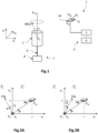
- FIG 1 is a schematic and partial perspective view of a device 1 for estimating an angular deviation ⁇ of a magnetic object 2 according to a first embodiment.
- the magnetic object 2 is here a cylindrical permanent magnet, for example annular.
- the estimation device 1 is capable of measuring the magnetic field at different measurement times, over a measurement duration T, in a reference frame (e r ,e ⁇ ,e z ), and of estimating the value of the angular deviation ⁇ of magnetic object 2 based on the measured values of the magnetic field.
- Magnet 2 is intended to be positioned at the center of the frame (e r ,e ⁇ ,e z ), so that the position P 0 of magnet 2 has the coordinates (0,0,0) in this frame.
- the position P 0 of magnet 2 corresponds to the coordinates of the geometric center of magnet 2, i.e. to the unweighted barycenter of all the points of magnet 2.
- the magnetic moment m of magnet 2 has the components (m r , m ⁇ , m z ) in the frame (e r ,e ⁇ ,e z ).
- Its norm, also called intensity or amplitude, is denoted ⁇ m ⁇ or m.
- the magnet is intended to be oriented so that the axis e z , corresponding to the axis of rotation of magnet 2, coincides with the reference axis A ref of the latter.
- the magnetic moment m will rotate around the direction e z .
- the estimation device 1 comprises a magnetic field measurement sensor having at least three measurement axes d 1 , d 2 , d 3 distinct two by two, that is to say that the measurement axes are not parallel to each other, and can thus comprise at least one triaxial magnetometer.
- the triaxial magnetometer M is placed at a defined position P M (r, ⁇ ,z) relative to the position P 0 of the magnet and therefore the center of the reference frame (e r ,e ⁇ ,e z ).
- This position is known and constant throughout the measurement duration T.
- Knowledge of the position may have a certain tolerance, for example of the order of 10% if we accept a relative uncertainty of the order of 20% on the estimated value of the angular deviation, or less, for example of the order of 1% for a relative uncertainty of the order of 2% on the value of the angular deviation.
- the magnetometer M therefore measures the amplitude and direction of the magnetic field B disturbed by the magnet 2. More precisely, it measures the norm of the orthogonal projection of the magnetic field B along the measurement axes d 1 , d 2 , d 3 .
- disturbed magnetic field B we mean the ambient magnetic field B a , i.e. not disturbed by the magnet 2, to which is added the magnetic field B d generated by the magnet 2.
- the estimation device 1 further comprises a calculation unit 4 capable of storing the measured values of the magnetic field during the measurement duration, and of determining the angular deviation. ⁇ of permanent magnet 2 from measurements of magnetic field B.
- the magnetometer M is connected to the calculation unit 4, electrically or otherwise, by an information transmission bus (not shown).
- the calculation unit 4 comprises a programmable processor 5 capable of executing instructions recorded on an information recording medium. It further comprises a memory 6 containing the instructions necessary for implementing certain steps of a method for estimating the angular deviation. ⁇ by the processor 5.
- the memory 6 is also adapted to store the information measured at each measurement moment.
- the computing unit 4 implements a mathematical model associating the measurements of the magnetometer M with the magnetic field and the position of the magnetometer M relative to the magnet 2 in the frame (e r ,e ⁇ ,e z ).
- This mathematical model is constructed from the equations of electromagnetism, in particular magnetostatics, and is parameterized in particular by geometric parameters representative of the position of the magnetometer M relative to the magnet 2 in the frame (e r ,e ⁇ ,e z ).
- the distance between the permanent magnet 2 and the magnetometer M is greater than 2 times, 3 times, or even 5 times the largest dimension of the permanent magnet 2. This dimension can be less than 20cm, or even less than 10cm, or even 5cm.
- the estimation device 1 also comprises a holding and rotation member 7, capable of holding the permanent magnet 2 relative to the magnetometer M, in a known and constant position during the measurement period.
- the holding and rotation member 7 comprises a motor 8 associated with an arm 9.
- the arm 9 can thus receive and hold the permanent magnet 2 and ensures the rotation of the latter.
- the arm 9 is made of a non-magnetic material and the motor 8 is sufficiently far from the permanent magnet 2 and the magnetometer M so as not to cause any disturbance to the measured magnetic field.
- the device 1 may not comprise a motor 8 and may be adapted so that the rotation of the arm 9 is carried out manually.
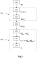
- FIG 2 illustrates a flowchart of an example method for estimating angular deviation ⁇ that the magnetic object 2 presents, the method being implemented by the device for estimating the figure 1 .
- the method comprises a step 100 of prior measurement of the ambient magnetic field B a , that is to say here the magnetic field not disturbed by the presence of the magnet 2.
- the magnetometer M is positioned at its measurement position P M , and carries out the measurement of the magnetic field B i a in the absence of the magnet 2, that is to say the acquisition of the projection of the magnetic field B a on each of the acquisition axes d 1 , d 2 , d 3 .
- the method then comprises a step 110 of measuring the disturbed magnetic field B by the magnet 2 rotating around its reference axis A ref during a measurement duration T.
- the permanent magnet 2 is positioned by the holding and rotation member 7 at the position P 0 with respect to the magnetometer M, such that the axis of rotation coincides with the reference axis A ref of the magnet 2.
- the magnetic moment m of the permanent magnet 2 is non-collinear with the reference axis A ref and forms, with respect to this axis, an angular deviation ⁇ to be determined.
- the permanent magnet 2 is rotated by the member 7 around the reference axis A ref .
- the reference axis A ref is static during the measurement duration T, in other words its position and its orientation in the reference frame (e r ,e ⁇ ,e z ) do not vary during the duration T.
- the rotation speed of the permanent magnet 2, denoted ⁇ is preferably constant during the duration T.
- the magnetometer M measures the projection of the vector magnetic field B along the acquisition axes d 1 , d 2 , d 3 .
- the method then comprises a step 130 of estimating the magnetic angular deviation. ⁇ of the permanent magnet 2, from the measurements B (t j ) of the disturbed magnetic field B .
- the calculation unit 4 identifies a so-called minimal magnetic field. B min d and a so-called maximum magnetic field B max d from the measurements B d (t j ) of the magnetic field B d .
- the computing unit calculates the angular deviation ⁇ from minimal fields B min d and maximum B max d identified, and geometric parameters representative of the position P M of the magnetometer with respect to the magnet 2.
- the minimal field B min d is associated with the magnetic moment m when the latter belongs to the half-plane P' of the plane P delimited by the reference axis A ref and not containing the magnetometer P M ( fig.3A ).
- the maximum field B max d is associated with the magnetic moment m belonging to the half-plane P" of the plane P delimited by the reference axis A ref and containing the magnetometer P M ( fig.3B ).
- the minimal field B min d associated with the moment m contained in the half-plane P' can be expressed analytically by the following equation (2):
- B min d ⁇ ⁇ r z 0 ,3 m d 5 sin ⁇ ⁇ d 2 3 ⁇ sin ⁇ ⁇ r 2 + cos ⁇ ⁇ rz ⁇ cos ⁇ ⁇ d 2 3 + cos ⁇ ⁇ z 2 ⁇ sin ⁇ ⁇ rz
- (r,z) are the coordinates P M of the magnetometer M in the plane P relative to the magnet 2
- r being the coordinate along an axis orthogonal to the reference axis A ref
- z being the coordinate along an axis parallel to the reference axis A ref
- d r 2 + z 2 is the distance between the magnetometer and the magnetic object.
- a sub-step 132 from equations (2) and (3), it is possible to calculate a CV coefficient no longer depending on the amplitude m of the magnetic moment, but only on the angular deviation ⁇ and geometric parameters representative of the positioning of the magnetometer M relative to the magnet 2 in the plane P.
- the coefficient of variation CV no longer depends on the amplitude m of the magnetic moment, and that it is formed from the product of a first term depending only on the angular deviation ⁇ and a second term depending only on known geometric parameters such as the coordinates (r,z) of the magnetometer M in the plane P and the distance d separating the magnetometer M from the magnet 2.
- the estimation method according to this first embodiment makes it possible to simply estimate the angular deviation.
- ⁇ of the magnetic object 2 on the basis of a simplified analytical model of the magnetic field B d generated by the magnet 2 associated with the measurements B d (t j ) of the magnetic field generated B d by the magnet 2 and with geometric parameters representative of the position of the magnetometer in a frame of reference of which one axis is collinear with the axis of rotation, itself being coincident with the reference axis A ref of the object 2. It is thus not necessary to determine the amplitude and the orientation of the magnetic moment, and this method is furthermore independent of the orientation of the magnetic sensor. Furthermore, it is not limited to low values of the angular deviation. Furthermore, it only requires the use of at least one triaxial magnetometer, and advantageously of a single triaxial magnetometer.
- the magnetometer M is positioned relative to the magnet 2 such that the coordinate z of the magnetometer in the plane P is greater than or substantially equal to the coordinate r.
- the coordinates r and z are advantageously substantially equal, thus making it possible to improve the accuracy of the estimation of the angular deviation cc.
- the magnetometer M is preferably located outside the reference axis A ref corresponding to the axis of rotation of the magnet 2, and outside the axis orthogonal to the reference axis A ref and passing through the position P 0 of the magnet 2.
- This arrangement makes it possible to clearly distinguish the minimum magnetic fields B min d and maximum B max d from each other.
- the magnetometer is arranged opposite the magnet 2 outside the deflection cone formed by the rotating magnetic moment m.
- multiple magnetometers M i can be used to estimate the angular deviation ⁇ .
- ⁇ i of the angular deviation ⁇ each associated with a magnetometer M i .
- the angular deviation ⁇ is then calculated by averaging, in a weighted or unweighted manner, the values ⁇ i obtained.
- the average is advantageously weighted according to the intensity of the signal received by each magnetometer.
- the estimation of the angular deviation ⁇ can be obtained by optimization by minimizing for example the squared error between the fields B min , i d And B max , i d previously identified by each magnetometer M i and the minimum fields B m ⁇ n , ⁇ d ⁇ ⁇ ⁇ , m ⁇ ,r i , z i and maximum B max , ⁇ d ⁇ ⁇ ⁇ , m ⁇ ,r i , z i expressed by equations (2) and (3).
- W i is here a weighting term, for example depending on the inverse of the noise associated with each magnetometer M i .
- this minimization expression can be adapted to the case where the magnetic sensor comprises a plurality of scalar magnetometers that measure the norm of the magnetic field. In this case, the squared error between the norm of the magnetic fields is minimized.
- the sampling frequency, the direction and/or the rotation speed are chosen so as to improve the quality of the estimation of the angular deviation at, and more precisely of the identification of the minimal magnetic fields.
- B min d and maximum B max d are chosen so as to improve the quality of the estimation of the angular deviation at, and more precisely of the identification of the minimal magnetic fields.
- B min d and maximum B max d are chosen so as to improve the quality of the estimation of the angular deviation at, and more precisely of the identification of the minimal magnetic fields.
- the rotation of the magnet 2 may also include phases of oscillation, i.e. of change in the direction of rotation, around these values. This reduces the relative uncertainty associated with the minimum and maximum values, which makes it possible to improve the quality of the identification of the minimum magnetic fields B min d and maximum B max d , and therefore of the estimation of the angular deviation cc.
- the amplitude m can thus be determined from the angular deviation ⁇ estimated, of the maximum magnetic field B max d identified, and said parameters geometric, namely the coordinates (r,z) of the magnetometer M and the distance d between the latter and the magnet 2.
- the magnitude m of the magnetic moment m can be calculated from the ratio between the norm ⁇ B max d ⁇ of the maximum magnetic field B max d identified, and the standard ⁇ B ⁇ max d ⁇ ⁇ r z ⁇ of the maximum magnetic field B ⁇ max d ⁇ ⁇ r z , for a unit amplitude of said magnetic moment m , expressed analytically by equation (7) from equation (3):
- B ⁇ max d ⁇ ⁇ r z 0 ,3 d 5 ⁇ sin ⁇ ⁇ d 2 3 + sin ⁇ ⁇ r 2 + cos ⁇ ⁇ rz ⁇ cos ⁇ ⁇ d 2 3 + cos ⁇ ⁇ z 2 + sin ⁇ ⁇ rz
- ⁇ is the previously estimated angular deviation and (r,z) and d are the known geometric parameters.
- m ⁇ B max d ⁇ ⁇ B ⁇ max d ⁇ ⁇ r z ⁇ which then allows us to characterize magnet 2 by the value of the amplitude m on the one hand, and the value of the angular deviation ⁇ on the other hand.
- the amplitude m can be calculated from the minimum magnetic field B min d identified and its analytical expression of equation (2).
- the use of the maximum magnetic field B max d however allows for better precision.
- FIG. 4A is a schematic and partial perspective view of a device 1 for estimating a so-called mean angular deviation ⁇ of a magnetic object 2, according to a second embodiment, the magnetic object here being a cylindrical permanent magnet, for example annular.
- the magnetic object here being a cylindrical permanent magnet, for example annular.
- instantaneous magnetic moment the magnetic moment vector estimated at a given instant
- instantaneous angular deviation the value of the angular deviation estimated at a given instant.
- the estimation device 1 is capable of estimating the instantaneous magnetic moment at different measurement times during a measurement duration T, in a reference frame XYZ. More precisely, the device 1 makes it possible to estimate the position of the permanent magnet 2, and its magnetic moment, at different times, in the reference frame XYZ. In other words, the device 1 makes it possible to locate the position and orientation of the permanent magnet 2 at different times in the reference frame XYZ.
- a three-dimensional direct reference frame (X, Y, Z) is defined, where the X and Y axes form a plane parallel to the measurement plane of the magnetometer network, and where the Z axis is oriented substantially orthogonally to the measurement plane.
- the terms “vertical” and “vertically” extend as being relative to an orientation substantially parallel to the Z axis, and the terms “horizontal” and “horizontally” as being relative to an orientation substantially parallel to the (X, Y) plane.
- the terms “lower” and “upper” extend as being relative to an increasing positioning when moving away from the measurement plane in the +Z direction.
- the position P d of permanent magnet 2 corresponds to the coordinates of the geometric center of magnet 2.
- the geometric center is the unweighted barycenter of all points of permanent magnet 2.
- the magnetic moment m of magnet 2 has the components (m x , m y , m z ) in the XYZ frame. Its norm, or intensity, is denoted ⁇ m ⁇ .
- the device 1 comprises a network of magnetometers M i distributed with respect to each other so as to form a measurement plane P mes .
- the number of magnetometers M i may be, for example, greater than or equal to 2, preferably greater than or equal to 16, for example equal to 32, in particular when they are triaxial magnetometers.
- the network of magnetometers however comprises at least 3 measurement axes distant from each other and not parallel two by two.
- the magnetometers M i are fixed to a protective plate 3 and can be located at the rear face of the plate 3, the latter being made of a non-magnetic material.
- fixed it is meant that they are assembled to the plate 3 without any degree of freedom. They are here aligned in rows and columns, but can be mutually positioned in a substantially random manner.
- the distances between each magnetometer and its neighbors are known and constant over time. For example, they can be between 1 cm and 4 cm.
- the magnetometers M i each have at least one measurement axis, for example three axes, denoted x i , y i , z i . Each magnetometer therefore measures the amplitude and direction of the magnetic field B disturbed by the permanent magnet. More precisely, each magnetometer M i measures the norm of the orthogonal projection of the magnetic field B along the axes x i , y i , z i of the magnetometer. The sensitivity of the magnetometers M i can be 4.10 -7 T.
- disturbed magnetic field B we mean the ambient magnetic field B a , i.e. not disturbed by the magnet, to which is added the magnetic field B d generated by the magnet.
- the estimation device 1 further comprises a calculation unit 4 capable of calculating the position and orientation of the magnetic moment of the magnet 2 in the XYZ frame from the measurements of the magnetometers M i . It also makes it possible to determine the average angular deviation of the permanent magnet 2 from the measurements of the magnetic moment.
- each magnetometer M i is electrically connected to the calculation unit 4 by an information transmission bus (not shown).
- the calculation unit 4 comprises a programmable processor 5 capable of executing instructions recorded on an information recording medium. It further comprises a memory 6 containing the instructions necessary for the implementation of certain steps of a method for estimating the mean angular deviation by the processor 5.
- the memory 6 is also adapted to store the information calculated at each measurement instant.
- the computing unit 4 implements a mathematical model associating the position of the permanent magnet 2 in the XYZ frame, as well as the orientation and intensity of the magnetic moment, with the measurements of the magnetometers M i .
- This mathematical model is constructed from the equations of electromagnetism, in particular magnetostatics, and is parameterized in particular by the positions and orientations of the magnetometers in the XYZ frame.
- the distance between the permanent magnet 2 and each magnetometer M i is greater than 2, or even 3 times the largest dimension of the permanent magnet 2. This dimension may be less than 20 cm, or even less than 10 cm, or even 5 cm.
- the estimation device 1 also comprises a holding and rotation member 7, capable of holding the permanent magnet 2 with respect to the measurement plane, in any position with respect to the measurement plane.
- the permanent magnet can be located above, that is to say opposite, the network of magnetometers M i , in a vertical position along the constant Z axis during the measurement duration T. It is also capable of ensuring the rotation of the magnet 2 along its reference axis A ref during the measurement duration. Also, during the measurement duration, the vertical position of the permanent magnet 2 is fixed and only its angular position varies due to the rotation along the reference axis A ref .
- the holding and rotation member 7 comprises a motor 8 associated with an arm 9. The arm 9 can thus receive and hold the permanent magnet 2 and ensures the rotation of the latter.
- the arm 9 is made of a non-magnetic material and the motor 8 is sufficiently far from the measuring plane P mes and the permanent magnet 2 so as not to cause any disturbance to the measured magnetic field.
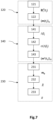
- FIG 5 is a flowchart of an exemplary method for estimating the mean angular deviation exhibited by a magnetic object, the method being implemented by the device for estimating the Figure 4A .
- the method comprises a step 100 of preliminary measurement of the ambient magnetic field B a , that is to say here the magnetic field not disturbed by the presence of the magnet 2.
- each of the magnetometers M i measures the magnetic field B i has in the absence of magnet 2, that is to say the projection of the magnetic field B a on each acquisition axis x i , y i , z i of the different magnetometers M i .
- the method then comprises a step 110 of measuring the magnetic field disturbed by the magnet 2 rotating around its reference axis A ref during a measurement duration T.
- the permanent magnet 2 is positioned with respect to the measurement plane P mes by the holding and rotation member 7, which defines the orientation of the reference axis A ref of the permanent magnet 2 with respect to the measurement plane P mes in the XYZ frame of reference.
- the permanent magnet 2 is positioned above the measurement plane P mes but any other positioning is possible.
- the orientation of the axis A ref can be arbitrary, but can advantageously be substantially orthogonal to the measurement plane P mes .
- the magnetic moment m of the permanent magnet 2 is non-collinear with the reference axis A ref and forms, with respect to this axis, an angular deviation ⁇ to be determined.
- the permanent magnet 2 is rotated by the member 7 around the reference axis A ref .
- the reference axis A ref is static during the measurement duration T, in other words its position and its orientation in the XYZ frame do not vary during the duration T.
- the rotation speed of the permanent magnet 2, denoted ⁇ , is preferably constant during the duration T.
- N instants t j of measurement.
- Each magnetometer M i at instant t j , measures the projection of the magnetic field B along the acquisition axis(es) x i , y i , z i .
- the method then comprises a step 120 of estimating the instantaneous magnetic moment m (t j ) of the permanent magnet 2, for each measurement instant t j , from the measurements of the disturbed magnetic field B i (t j ).
- the calculation unit 4 determines the coordinates of the position of the permanent magnet 2 as well as the components m x , m y , m z of the instantaneous magnetic moment, in the XYZ frame of reference.
- a time series ⁇ m (t j ) ⁇ N of N instantaneous vectors of the magnetic moment m (t j ) is thus obtained.
- the time series ⁇ m (t j ) ⁇ N forms a circle C which extends around the reference axis A ref .
- the circle C can be associated with instantaneous radii R(t j ) relative to the instantaneous magnetic moments m (t j ), as well as a mean radius R whose value depends on the mean angular deviation ⁇ to be determined.
- the method then comprises a step 230 of estimating the mean angular deviation. ⁇ formed by the angular difference between the magnetic moment m of the magnetic dipole and the reference axis A ref .
- the calculation unit estimates a vector m 0 that is invariant during the rotation of the permanent magnet 2.
- the time average is performed, over the N measurement times t j , of each coordinate m x (t j ), m y (t j ), m z (t j ) of the instantaneous magnetic moment m (t j ) in the XYZ frame.
- the operator ⁇ > N corresponds to the arithmetic time average, possibly weighted, over the N measurement times.
- the calculation unit estimates a parameter representative of an average amplitude of the angular deviation of the instantaneous magnetic moments relative to the reference axis.
- the estimate of the mean angular deviation can be obtained from the arc-sine of the ratio between the mean radius R previously estimated and the time average of the norm of the instantaneous magnetic moment ⁇ m (t j ) ⁇ > N over the N instants t j of measurement.
- the adjustment of the value of the mean radius R can be achieved in a known manner, by classical regression methods, for example multilinear or polynomial.
- the magnetic object is a permanent magnet with rotational symmetry around its reference axis A ref . It is positioned, for example, 4 cm vertically from a network of 32 triaxial magnetometers with a sensitivity of 4.10 -7 T spaced, for example, 4 cm apart.
- the rotation speed is ⁇ /5 rad/s (1 revolution in 10s) and the sampling frequency is 140Hz.
- the magnetic object makes a single rotation and the determination device acquires 1400 measurement instants.
- the calculation unit estimates the average intensity of the magnetic moment at 0.165 Am 2 for a RMS (Root Mean Square) noise of 5.10 -4 Am 2 .
- the determination device estimates at 0.01° the average angular deviation between the reference axis of the magnet and its magnetic axis.
- the measurement duration T and the rotation speed ⁇ are chosen so that, during the duration T, the magnetic object has made an integer number of complete revolutions, for example a single revolution. Furthermore, in order to obtain an angular distribution substantially homogeneous measurement data around the reference axis A ref over the duration T, the elementary rotation ⁇ j between two measurement times t j and t j+1 is substantially constant.
- an angular homogenization step can be implemented.
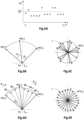
- FIG. 6A to 6E and the figure 7 illustrate a step 140 of homogenizing the angular distribution of the instantaneous magnetic moments around the reference axis A ref during the measurement duration T.
- This step is based on the resampling of the instantaneous magnetic moments during the measurement duration T by interpolation, here by means of a linear interpolation method, such that the angular differences between two successive instantaneous magnetic moments are substantially constant.
- an initial time series of N instantaneous magnetic moments which have an inhomogeneous angular distribution around the reference axis A ref during the duration T is resampled, for example the time series ⁇ m (t j ) ⁇ N estimated for example during the sub-step 122, to obtain a so-called homogenized time series ⁇ m h (t j ) ⁇ N' of N' instantaneous magnetic moments which have a substantially homogeneous angular distribution.
- This step is advantageous when, as illustrated by the Figures 6A to 6C , the angular distribution of the instantaneous magnetic moments around the reference axis A ref is not homogeneous over the duration T. This is reflected by the fact that the angular deviations ⁇ j defined between two instantaneous magnetic moments m (t j ) and m (t j+1 ), at successive measurement times t j and t j+1 , exhibit a strong dispersion around the mean value ⁇ .
- the vector m 0 calculated during the sub-step 231 described above, may not be rotationally invariant, i.e. may not be collinear with the reference axis A ref .
- This error in the calculation of the vector m 0 may introduce a bias into the estimated value of the mean angular deviation. ⁇ .
- This homogenization step 140 thus makes it possible to reduce the error in the estimation of the invariant vector m 0 .
- this homogenization step 140 may include an optional sub-step 141 in which the angular deviations ⁇ j defined by the estimated magnetic moments m ( tj ) and m ( t j+1 ) at successive measurement times of the initial time series are first estimated, for example here ⁇ m ( t j ) ⁇ N .
- the estimation of the dispersion of the angular deviations ⁇ j can be obtained by calculating the standard deviation ⁇ ⁇ , or an equivalent parameter, on the estimated angular deviations ⁇ j . If the value of the standard deviation ⁇ ⁇ is less than a predetermined threshold, the measurement data have a substantially homogeneous angular distribution. Otherwise, the homogenization of the angular distribution of the instantaneous magnetic moments around the reference axis A ref is carried out during the measurement duration T.
- a sub-step 143 the initial time series ⁇ m (t j ) ⁇ N is resampled by interpolation to obtain a so-called homogenized time series ⁇ m h (t k ) ⁇ N' of N' interpolated magnetic moments, whose angular deviations ⁇ 0 are substantially constant. This is an oversampling when N'>N but the number N' can be less than or equal to N.
- an illustrated approach on the Figure 6D consists in discretizing the angular difference ⁇ j between two successive instantaneous magnetic moments m (t j ) and m (t j+1 ) of the initial time series ⁇ m (t j ) ⁇ N when its value is greater than a predetermined threshold value ⁇ 0 , for example by linear interpolation (as shown in the Figure 6D ) or by another interpolation, for example polynomial.
- This sub-step 143 can be applied to all the pairs of magnetic moments m (t j ) and m (t j+1 ) measured at successive instants, for which ⁇ j > ⁇ 0 .
- three interpolated vectors m ⁇ 21 , m ⁇ 22 , m ⁇ 23 are calculated between the instantaneous magnetic moments m (t 2 ) and m (t 3 ) such that the angular separations between these magnetic moments m (t 2 ), m ⁇ 21 , m ⁇ 22 , m ⁇ 23 and m (t 3 ) are substantially constant and equal to ⁇ 0 .
- the iteration on k continues as long as the angular difference between m ⁇ k+1 and m (t j+1 ) is greater than ⁇ 0 , and as long as the product of the number k of iterations and ⁇ 0 is less than one or more times 2 ⁇ .
- the unit vector e j,j+1 is defined at j and j+1 such that the angular deviations between m ( tj ) and m ⁇ k+1 on the one hand, and between m ⁇ k+1 and m ( t j+1 ) on the other hand, are less than the angular deviation ⁇ j between m ( t j ) and m ( t j+1 ).
- sub-step 143 of calculating the homogenized time series ⁇ m h ⁇ N' it is possible to perform an oversampling of the initial time series, for example ⁇ m (t j ) ⁇ N , preferably by polynomial interpolation, possibly using splines, to thus obtain a new time series to be homogenized by means of sub-step 143 described previously.
- the standard deviation calculated on the angular deviations ⁇ ' associated with the homogenized time series ⁇ m h ⁇ N' is then minimal or substantially zero to the extent that they are substantially equal to the value ⁇ 0 .
- the instantaneous magnetic moments m h (t k ) then present a substantially homogeneous angular distribution around the reference axis A ref during the measurement duration T.
- step 230 The method of estimating the mean angular deviation ⁇ between the magnetic axis and the reference axis is then continued with step 230 described above.
- the invariant vector m 0 is deduced from the N' instantaneous magnetic moments m h (t k ) of the homogenized time series ⁇ m h ⁇ N' and no longer from the N instantaneous magnetic moments m (t j ) of the time series ⁇ m ⁇ N obtained during substep 122.
- the mean radius R of the circle C is calculated from the magnetic moments m h (t k ) of the homogenized time series and/or from the magnetic moments m ⁇ (t j ) of the filtered time series ⁇ m ⁇ (t j ) ⁇ N described later, and not from the magnetic moments m (t j ) of the time series obtained during sub-step 122.
- a step 150 of low-pass filtering of the values of the components of the instantaneous magnetic moments in the XYZ frame in order to reduce the temporal dispersion, in other words the measurement noise, that they may present, for example using an arithmetic or exponential moving average calculated on a number K of samples.
- This is particularly advantageous when the average angular deviation is less than 0.2° and/or when the noise associated with the components of the magnetic moments is of the same order of magnitude as the value of the average radius. R from circle C.
- FIG. 8A is a diagram which schematically illustrates the temporal dispersion of the values of the components m (t j ) of the instantaneous magnetic moments m (t j ) in the XYZ frame, here from the time series ⁇ m (t j ) ⁇ N obtained during sub-step 122.
- This dispersion of the values of the components m (t j ) over time can induce a bias in the estimation of the mean angular deviation ⁇ .
- the step 150 of low-pass filtering by a sliding average, or moving average can be carried out ( figure 9 ).
- the unit calculates the standard deviation ⁇ ( ⁇ m (t j ) ⁇ ) on the N values of the norm ⁇ m (t j ) ⁇ of the instantaneous magnetic moments, or an equivalent parameter representative of the dispersion of the values of the norm ⁇ m (t j ) ⁇ of the instantaneous magnetic moments. If the value of the standard deviation ⁇ ( ⁇ m (t j ) ⁇ ) is greater than a predetermined threshold value, a filtering of the 3N values of components m (t j ) is carried out.
- a sub-step 152 the unit applies a low-pass filter H K (t j ), here by sliding average on K samples, for example an arithmetic or exponential average, or an equivalent type of filter, on the time series of 3N values ⁇ m (t j ) ⁇ N components of the instantaneous magnetic moments in the XYZ frame.
- H K (t j ) H K (t j ).
- m ⁇ (t j ) is the filtered values of the components of the instantaneous magnetic moment in the XYZ frame, at time t j .
- this step 150 of low-pass filtering of the components of the instantaneous magnetic moments can be applied to the time series ⁇ m (t j ) ⁇ N obtained during sub-step 122, as to the homogenized time series ⁇ m h (t k ) ⁇ N' .
- the number K of samples is chosen so that the product of K with the average angular deviation ⁇ j > of the time series considered, for example the series ⁇ m (t j ) ⁇ N from sub-step 122, is less than a given value, for example 45°, and preferably 10°, or even 5° and preferably 1°.
- the average angular deviation ⁇ j > can be obtained by the rotation speed of the rotation member multiplied by the sampling frequency. This avoids applying overly restrictive filtering to the time series considered which could risk masking the dynamics of the rotation signal.
- homogenization step 140 It is advantageous to perform the homogenization step 140 before the step 231 of estimating the invariant vector m 0 . Furthermore, it is advantageous to perform the filtering step 150 before the step 232 of estimating the mean radius. R of circle C. Finally, it is advantageous to carry out filtering step 150 before homogenization step 140 so that the time series taken into account in homogenization step 140 is less noisy.
- the method of estimating the mean angular deviation ⁇ includes an additional sub-step of classifying the permanent magnet 2 with a view to sorting according to a reference value ⁇ th of the angular deviation, it may be advantageous to determine the number K of samples to be taken into account in the moving average so that the bias value is substantially zero at the reference value ⁇ th .
- the classification sub-step involves comparing the estimated value of the mean angular deviation ⁇ with the predetermined reference value ⁇ th .
- a classification and therefore a sorting of the magnetic objects can be carried out according to whether the average angular deviation ⁇ is greater or less than the reference value ⁇ th .
- the permanent magnet 2 is usable when its estimated angular deviation is less than or equal to the reference value ⁇ th and that it should be discarded when it is greater than the reference value.
- the bias is positive, i.e. the actual value ⁇ r is lower than the estimated value.
- the permanent magnet can then be used.
- the bias is negative, i.e. the actual value ⁇ r is greater than the estimated value.
- the permanent magnet should then be discarded.
- the reference value and the sorting decision depend on the intended applications for the permanent magnet.
- This positioning step includes a sub-step 91 of estimating a parameter representative of the dispersion of the values of the intensity of the instantaneous magnetic moment, for different vertical positions along the Z axis above the measurement plane P mes .
- steps 110 and 120 are performed for different values of vertical positioning of the object along the Z axis.
- a time series of instantaneous magnetic moments is thus obtained, for example the time series ⁇ m (t j ) ⁇ N obtained during sub-step 122, and for example the standard deviation ⁇ ( ⁇ m (t j ) ⁇ ) on the N values of the intensity ⁇ m (t j ) ⁇ of the instantaneous magnetic moments is deduced.
- a spatial series which gives the value of the standard deviation ⁇ ( ⁇ m (t j ) ⁇ ) for different vertical positions Z occupied by the magnetic object.
- a vertical position value Z P is selected for which the value of the standard deviation ⁇ ( ⁇ m (t j ) ⁇ ) on the intensity of the instantaneous magnetic moment is less than a threshold value ⁇ ref . Then, the magnetic object is positioned so that it occupies the vertical position Z P .
- step 100 The method of estimating the mean angular deviation ⁇ is then continued with step 100 and steps 120 and 230 described previously, possibly supplemented by steps 140 and 150.
- the method may comprise an additional step of estimating a quality indicator of the measurements carried out during the measurement duration T. This step may take place, preferably, after the execution of step 120 or step 150.
- the calculation unit 4 determines the standard deviation ⁇ R on the N values of the instantaneous radius which is estimated from the instantaneous magnetic moments m (t j ).
- the quality indicator here is the quantity ⁇ R / ⁇ N which makes it possible to characterize the precision of the series of measurements.
- quality indicators can be used from the standard deviation ⁇ R , for example asin( ( ⁇ R / ⁇ N)/ ( ⁇ ⁇ m (t j ) ⁇ > N ) ) or atan( ( ⁇ R / ⁇ N)/( ⁇ m 0 ⁇ ) ).
- the standard deviation ⁇ R on the N values of the instantaneous radius can be compared to a reference value ⁇ ( R ) previously determined.
- This value ⁇ ( R ) can be determined by making a large number Q of estimates of the mean radius R for the same type of permanent magnet 2.
- the number Q can be greater than 100 or even greater than or equal to 1000.
- the average radius R is for example estimated by executing steps 120 and 230, possibly supplemented by steps 140 and 150.
- Q is a non-zero natural integer, preferably greater than or equal to 50, or even 100.
Landscapes
- Physics & Mathematics (AREA)
- General Physics & Mathematics (AREA)
- Condensed Matter Physics & Semiconductors (AREA)
- Engineering & Computer Science (AREA)
- Remote Sensing (AREA)
- Life Sciences & Earth Sciences (AREA)
- Electromagnetism (AREA)
- Environmental & Geological Engineering (AREA)
- Geology (AREA)
- General Life Sciences & Earth Sciences (AREA)
- Geophysics (AREA)
- Measuring Magnetic Variables (AREA)
Claims (17)
- Verfahren zum Schätzen einer Winkelabweichung (
α ) zwischen einer Referenzachse (Aref) eines magnetischen Objekts (2) und einer magnetischen Achse, die kolinear zu einem magnetischen Moment (m) des magnetischen Objekts (2) verläuft, umfassend die folgenden Schritte:a) Positionieren (90; 110) des magnetischen Objekts (2) gegenüber mindestens einem Magnetometer (Mi), der dazu ausgelegt ist, ein Magnetfeld (B) in Gegenwart des magnetischen Objekts (2) zu messen;b) Drehen (110) des magnetischen Objekts (2) um die Referenzachse (Aref);c) Messen (110) des Magnetfelds (Bi (tj)) zu verschiedenen Zeitpunkten (tj) einer Messdauer (T) mit dem Magnetometer (Mi) während des Drehens;d) Schätzen (130; 230) der Winkelabweichung (α ) anhand der Messungen (Bi (tj)) des Magnetfelds (Bi ). - Verfahren nach Anspruch 1, wobei der Schritt des Schätzens (130) Folgendes umfasst:- einen Unterschritt des Identifizierens eines minimalen Magnetfelds (

 - einen Unterschritt des Berechnens der Winkelabweichung (
α ) anhand des identifizierten minimalen (
- Verfahren nach Anspruch 2, wobei während des Unterschritts des Identifizierens das minimale (


- Verfahren nach Anspruch 2 oder 3, wobei die geometrischen Parameter (r,z; d) die Koordinaten (r,z) und der Abstand (d) des Magnetometers (M) in Bezug auf das magnetische Objekt (2) in einer Ebene sind, die durch die Referenzachse (Aref) verläuft und das Magnetometer (M) enthält.
- Verfahren nach einem der Ansprüche 2 bis 4, wobei die Winkelabweichung (
α ) anhand eines Koeffizienten (CV), der dem Verhältnis der Norm des Vektors, der aus der Subtraktion des minimalen (


- Verfahren nach einem der Ansprüche 2 bis 5, wobei die Winkelabweichung (
α ) anhand der folgenden Gleichung berechnet wird:
- Verfahren nach einem der Ansprüche 1 bis 6, wobei das magnetische Objekt (2) während des Schritts des Drehens mindestens eine Drehung um die Referenzachse (Aref) ausführt.
- Verfahren nach einem der Ansprüche 1 bis 7, wobei das mindestens eine Magnetometer (M) mindestens drei Achsen zum Erfassen des Magnetfelds umfasst, wobei die Erfassungsachsen nicht parallel zueinander verlaufen.
- Verfahren nach einem der Ansprüche 1 bis 8, wobei das mindestens eine Magnetometer (M) ein einzelnes dreiachsiges Magnetometer ist.
- Verfahren nach einem der Ansprüche 1 bis 9, wobei das mindestens eine Magnetometer (M) außerhalb der Referenzachse (Aref) oder außerhalb der durch das magnetische Objekt verlaufenden Senkrechten zur Referenzachse (Aref) positioniert ist.
- Verfahren nach einem der Ansprüche 1 bis 10, wobei das mindestens eine Magnetometer (M) im Verhältnis zum magnetischen Objekt an einer Koordinate z entlang einer Achse (ez), die parallel zur Referenzachse (Aref) verläuft, und an einer Koordinate r entlang einer Achse (er), die orthogonal zur Referenzachse (Aref) verläuft, positioniert wird, so dass die Koordinate z größer oder gleich der Koordinate r ist.
- Verfahren zum Charakterisieren eines magnetischen Objekts (2), das eine Winkelabweichung (
α ) zwischen einer Referenzachse (Aref) des magnetischen Objekts (2) und einer magnetischen Achse, die kolinear zu einem magnetischen Moment (m) des magnetischen Objekts (2) verläuft, aufweist, umfassend die folgenden Schritte:- Implementieren des Verfahrens zum Schätzen der Winkelabweichung (α ) nach einem der Ansprüche 2 bis 11 in Abhängigkeit von Anspruch 2;- Berechnen einer Amplitude (m) des mit dem magnetischen Objekt (2) verbundenen magnetischen Moments (m) anhand der geschätzten Winkelabweichung (α ), des identifizierten maximalen Magnetfelds (
- Verfahren nach Anspruch 12, wobei die Amplitude (m) des magnetischen Moments anhand des Verhältnisses zwischen der Norm des maximalen Magnetfelds (


α die zuvor geschätzte Winkelabweichung ist, d der Abstand zwischen dem Magnetometer (M) und dem magnetischen Objekt (2) ist, z und r Koordinaten des Magnetometers (M) im Verhältnis zum magnetischen Objekt (2) entlang einer Achse sind, die jeweils parallel (ez) und orthogonal (er) zur Referenzachse (Aref) verläuft, und wobei a und b vorbestimmte Koeffizienten sind. - Schätzungsverfahren nach Anspruch 1, umfassend die folgenden Schritte:- Positionieren (90; 110) des magnetischen Objekts (2) gegenüber einer Messebene (Pmes), die durch eine Anordnung von Magnetometern (Mi) definiert wird, die dazu ausgelegt sind, ein Magnetfeld (B) in Gegenwart des magnetischen Objekts (2) zu messen;- Schätzen (120) eines momentanen magnetischen Moments (m(tj)) des magnetischen Objekts (2) zu den verschiedenen Messzeitpunkten (tj) anhand des gemessenen Magnetfelds (Bi (tj));- Schätzen (230) der mittleren Winkelabweichung (
α ) anhand der momentanen magnetischen Momenten (m(tj)). - Verfahren nach Anspruch 14, wobei der Schritt des Schätzens (230) der mittleren Winkelabweichung (
α ) einen Unterschritt des Schätzens (231) eines invarianten Vektors (mo ), der sich um die Referenzachse (Aref) dreht, anhand der momentanen magnetischen Momenten (m(tj)) umfasst, wobei das Schätzen (230) der mittleren Winkelabweichung (α ) ferner anhand des invarianten Vektors (mo ) ausgeführt wird. - Vorrichtung zum Schätzen (1) einer Winkelabweichung (
α ) zwischen einer Referenzachse (Aref) eines magnetischen Objekts (2) und einer magnetischen Achse, die kolinear zu einem magnetischen Moment (m) des magnetischen Objekts (2) verläuft, umfassend:- mindestens ein Magnetometer (Mi), das dazu ausgelegt ist, ein durch das magnetische Objekt (2) gestörtes Magnetfeld zu jedem Messzeitpunkt einer Dauer (T) zu messen;- ein Halte- und Drehbauteil (7), das dazu ausgelegt ist, das magnetische Objekt (2) in einer bestimmten Position gegenüber dem mindestens einen Magnetometer (Mi) festzuhalten und das magnetische Objekt (2) entlang seiner Referenzachse (Aref) in Drehung zu versetzen;- einen Prozessor (5), der dazu konfiguriert ist, das Verfahren nach einem der Ansprüche 1 bis 15 zu implementieren. - Informationsaufzeichnungsmedium, das Anweisungen umfasst, die die Schätzvorrichtung (1) nach Anspruch 16 dazu veranlassen, die Schritte des Verfahrens nach einem der Ansprüche 1 bis 15 auszuführen.
Applications Claiming Priority (3)
| Application Number | Priority Date | Filing Date | Title |
|---|---|---|---|
| FR1656785A FR3054040B1 (fr) | 2016-07-13 | 2016-07-13 | Procede d’estimation d’une deviation angulaire moyenne entre l’axe magnetique et un axe de reference d’un objet magnetique |
| FR1661693A FR3054041B1 (fr) | 2016-07-13 | 2016-11-30 | Procede d’estimation d’une deviation angulaire entre l’axe magnetique et un axe de reference d’un objet magnetique |
| PCT/FR2017/051870 WO2018011492A1 (fr) | 2016-07-13 | 2017-07-10 | Procede d'estimation d'une deviation angulaire entre l'axe magnetique et un axe de reference d'un objet magnetique |
Publications (2)
| Publication Number | Publication Date |
|---|---|
| EP3485299A1 EP3485299A1 (de) | 2019-05-22 |
| EP3485299B1 true EP3485299B1 (de) | 2024-09-18 |
Family
ID=56855734
Family Applications (1)
| Application Number | Title | Priority Date | Filing Date |
|---|---|---|---|
| EP17745436.0A Active EP3485299B1 (de) | 2016-07-13 | 2017-07-10 | Verfahren zur schätzung einer winkelabweichung zwischen der magnetischen achse und einer referenzachse eines magnetischen objekts |
Country Status (6)
| Country | Link |
|---|---|
| US (1) | US11480422B2 (de) |
| EP (1) | EP3485299B1 (de) |
| CN (1) | CN109716168B (de) |
| FR (2) | FR3054040B1 (de) |
| MX (1) | MX2019000455A (de) |
| WO (1) | WO2018011492A1 (de) |
Families Citing this family (10)
| Publication number | Priority date | Publication date | Assignee | Title |
|---|---|---|---|---|
| FR3080186B1 (fr) * | 2018-04-16 | 2020-05-08 | Commissariat A L'energie Atomique Et Aux Energies Alternatives | Procede de calibration d'un reseau de magnetometres |
| CN110455178A (zh) * | 2019-09-06 | 2019-11-15 | 安徽中科智能感知产业技术研究院有限责任公司 | 一种基于三轴磁力计的旋转部件旋转状态参数检测传感器 |
| CN110824570B (zh) * | 2019-10-28 | 2021-07-27 | 杭州电子科技大学 | 一种三轴磁传感器的本体磁性校正方法 |
| TWI716252B (zh) * | 2020-01-03 | 2021-01-11 | 中華精測科技股份有限公司 | 旋轉及定位複數測物之方法 |
| FR3107122B1 (fr) * | 2020-02-07 | 2022-02-04 | Commissariat Energie Atomique | Réseau de magnétomètres fonctionnant en champ nul et procédé associé de calibration des couplages intermagnétomètres |
| EP3875915B1 (de) * | 2020-03-06 | 2023-07-19 | Melexis Technologies SA | Vorrichtung, system und verfahren zur bestimmung einer position eines magneten |
| AT524535B1 (de) * | 2021-01-15 | 2022-07-15 | Avl List Gmbh | Verfahren zur Korrektur einer Fehlausrichtung wenigstens eines Wellenstrangs |
| CN114468945A (zh) * | 2022-01-28 | 2022-05-13 | 上海安翰医疗技术有限公司 | 一种磁球校准方法和磁球校准装置 |
| EP4390636A1 (de) * | 2022-12-22 | 2024-06-26 | Advanced Magnetic Interaction, AMI | Permanentmagnetanordnungen für passive zubehörteile |
| CN118330751B (zh) * | 2024-06-12 | 2024-10-29 | 江苏多维科技有限公司 | 一种目标跟踪系统 |
Family Cites Families (14)
| Publication number | Priority date | Publication date | Assignee | Title |
|---|---|---|---|---|
| US6736222B2 (en) * | 2001-11-05 | 2004-05-18 | Vector Magnetics, Llc | Relative drill bit direction measurement |
| US7425829B2 (en) * | 2003-10-14 | 2008-09-16 | Merlin Technology, Inc. | Tracking positions of personnel, vehicles, and inanimate objects |
| DE102005051357B4 (de) * | 2005-10-25 | 2013-08-14 | Rayonex Schwingungstechnik Gmbh | Vorrichtung und Verfahren zur Lokalisierung eines Geräts |
| US7868610B2 (en) * | 2006-06-09 | 2011-01-11 | The Regents Of The University Of California | Angular motion tracking sensor |
| WO2010065161A1 (en) * | 2008-12-02 | 2010-06-10 | Schlumberger Canada Limited | Systems and methods for well positioning using phase relations between transverse magnetic field components of a transverse rotating magnetic source |
| CN102510997B (zh) * | 2009-09-26 | 2015-01-21 | 阿尔卑斯电气株式会社 | 地磁力检测装置 |
| US8508221B2 (en) * | 2010-08-30 | 2013-08-13 | Everspin Technologies, Inc. | Two-axis magnetic field sensor having reduced compensation angle for zero offset |
| US8766383B2 (en) * | 2011-07-07 | 2014-07-01 | Samsung Electronics Co., Ltd. | Method and system for providing a magnetic junction using half metallic ferromagnets |
| FR2996653B1 (fr) | 2012-10-05 | 2015-01-02 | Commissariat Energie Atomique | Anneau magnetique apte a etre fixe de facon amovible sur un crayon ou un effaceur |
| FR3003039B1 (fr) * | 2013-03-08 | 2015-03-06 | Commissariat Energie Atomique | Procede de reconnaissance automatique d'un objet magnetique |
| CN103278860B (zh) * | 2013-05-06 | 2015-10-28 | 国家海洋局第二海洋研究所 | 一种深海三分量磁力仪的现场自校正方法 |
| FR3015049B1 (fr) | 2013-12-16 | 2015-12-25 | Commissariat Energie Atomique | Procede de localisation d'objets magnetiques mobiles presentes devant un reseau de magnetometres |
| FR3037409B1 (fr) * | 2015-06-10 | 2017-07-21 | Commissariat Energie Atomique | Procede de controle de la fabrication d'un aimant et dispositif associe |
| CN105487027B (zh) * | 2016-01-04 | 2018-10-19 | 中国科学院物理研究所 | 三维矢量磁矩测量仪 |
-
2016
- 2016-07-13 FR FR1656785A patent/FR3054040B1/fr active Active
- 2016-11-30 FR FR1661693A patent/FR3054041B1/fr active Active
-
2017
- 2017-07-10 WO PCT/FR2017/051870 patent/WO2018011492A1/fr not_active Ceased
- 2017-07-10 EP EP17745436.0A patent/EP3485299B1/de active Active
- 2017-07-10 CN CN201780054445.XA patent/CN109716168B/zh active Active
- 2017-07-10 US US16/317,434 patent/US11480422B2/en active Active
- 2017-07-10 MX MX2019000455A patent/MX2019000455A/es unknown
Also Published As
| Publication number | Publication date |
|---|---|
| CN109716168B (zh) | 2022-05-24 |
| EP3485299A1 (de) | 2019-05-22 |
| WO2018011492A1 (fr) | 2018-01-18 |
| FR3054041B1 (fr) | 2018-08-17 |
| US11480422B2 (en) | 2022-10-25 |
| MX2019000455A (es) | 2019-12-19 |
| FR3054040A1 (fr) | 2018-01-19 |
| FR3054040B1 (fr) | 2018-08-17 |
| US20190301848A1 (en) | 2019-10-03 |
| FR3054041A1 (fr) | 2018-01-19 |
| CN109716168A (zh) | 2019-05-03 |
Similar Documents
| Publication | Publication Date | Title |
|---|---|---|
| EP3485299B1 (de) | Verfahren zur schätzung einer winkelabweichung zwischen der magnetischen achse und einer referenzachse eines magnetischen objekts | |
| EP3360031B1 (de) | Verfahren zur verfolgung einer position eines magneten durch differenzmessung | |
| EP2718670B1 (de) | Vereinfachtes verfahren zur schätzung der ausrichtung eines objekts und lagesensor zur durchführung dieses verfahrens | |
| FR3067139B1 (fr) | Procede de suivi d’un aimant par un reseau de magnetometres, comportant une phase d’identification de la presence de l’aimant et d’un perturbateur magnetique | |
| EP3807594B1 (de) | Verfahren zum kalibrieren von in einem objekt montierten magnetometern | |
| EP3898286B1 (de) | Verfahren zur erhaltung der verformung eines unter belastung fahrenden reifens | |
| WO2018219889A1 (fr) | Procede d'estimation de la position d'un aimant comportant une phase d'identification d'un perturbateur magnetique | |
| EP3898285B1 (de) | Verfahren zur erhaltung der verformung eines unter belastung fahrenden reifens | |
| EP2378305B1 (de) | Methode und Vorrichtung zur Kompensierung eines gemessenen Magnetfeldes, Methode und System zur Lokalisierung eines Objektes. | |
| EP3655800B1 (de) | Verfahren und vorrichtung zur magnetfeldmessung durch magnetometer | |
| EP1861679A1 (de) | Verfahren und vorrichtung zur erlangung einer geometrischen form | |
| EP4038482B1 (de) | System zur erfassung eines von einem gerät auf einer schreiboberfläche zurückgelegten weges, und entsprechendes verfahren und informations-aufzeichnungsmedium | |
| EP3556287B1 (de) | Kalibrierungsverfahren eines magnetometernetzwerks | |
| WO2009059929A1 (fr) | Procede de trajectographie passive par mesures d'angles | |
| WO2007141290A1 (fr) | Procede de localisation d'un objet magnetique, produit programme d'ordinateur, moyen de stockage et dispositif de localisation correspondants | |
| EP2372912A1 (de) | Eichungsverfahren und -system, Datenträger für dieses Verfahren | |
| EP2409118A2 (de) | Einrichtung zur magnetischen messung der rotation einer magnetisierten kugel und verfahren zur messung der rotation der kugel | |
| EP4214598B1 (de) | Verfahren und vorrichtung zur verfolgung eines endes eines utensils mit rekalibrierung eines abstandes zwischen dem ende und einem am utensil sicher befestigten magnetischen objekt | |
| FR3153425A1 (fr) | Procédé de filtrage d’un signal | |
| FR3153412A1 (fr) | Procédé de caractérisation du comportement d'un arbre en rotation par utilisation d’ellipses équivalentes | |
| FR3153411A1 (fr) | Procédé de contrôle d’un arbre en rotation par décomposition de mesures dudit arbre en composantes stationnaire et de perturbation | |
| FR3092224A1 (fr) | Procédé d’obtention de la déformation d’un pneumatique sous charge en roulage |
Legal Events
| Date | Code | Title | Description |
|---|---|---|---|
| STAA | Information on the status of an ep patent application or granted ep patent |
Free format text: STATUS: UNKNOWN |
|
| STAA | Information on the status of an ep patent application or granted ep patent |
Free format text: STATUS: THE INTERNATIONAL PUBLICATION HAS BEEN MADE |
|
| PUAI | Public reference made under article 153(3) epc to a published international application that has entered the european phase |
Free format text: ORIGINAL CODE: 0009012 |
|
| STAA | Information on the status of an ep patent application or granted ep patent |
Free format text: STATUS: REQUEST FOR EXAMINATION WAS MADE |
|
| 17P | Request for examination filed |
Effective date: 20190109 |
|
| AK | Designated contracting states |
Kind code of ref document: A1 Designated state(s): AL AT BE BG CH CY CZ DE DK EE ES FI FR GB GR HR HU IE IS IT LI LT LU LV MC MK MT NL NO PL PT RO RS SE SI SK SM TR |
|
| AX | Request for extension of the european patent |
Extension state: BA ME |
|
| DAV | Request for validation of the european patent (deleted) | ||
| DAX | Request for extension of the european patent (deleted) | ||
| RAP3 | Party data changed (applicant data changed or rights of an application transferred) |
Owner name: COMMISSARIAT A L'ENERGIE ATOMIQUE ET AUX ENERGIES ALTERNATIVES Owner name: ADVANCED MAGNETIC INTERACTION, AMI |
|
| STAA | Information on the status of an ep patent application or granted ep patent |
Free format text: STATUS: EXAMINATION IS IN PROGRESS |
|
| 17Q | First examination report despatched |
Effective date: 20211026 |
|
| GRAP | Despatch of communication of intention to grant a patent |
Free format text: ORIGINAL CODE: EPIDOSNIGR1 |
|
| STAA | Information on the status of an ep patent application or granted ep patent |
Free format text: STATUS: GRANT OF PATENT IS INTENDED |
|
| INTG | Intention to grant announced |
Effective date: 20240507 |
|
| GRAS | Grant fee paid |
Free format text: ORIGINAL CODE: EPIDOSNIGR3 |
|
| GRAA | (expected) grant |
Free format text: ORIGINAL CODE: 0009210 |
|
| STAA | Information on the status of an ep patent application or granted ep patent |
Free format text: STATUS: THE PATENT HAS BEEN GRANTED |
|
| AK | Designated contracting states |
Kind code of ref document: B1 Designated state(s): AL AT BE BG CH CY CZ DE DK EE ES FI FR GB GR HR HU IE IS IT LI LT LU LV MC MK MT NL NO PL PT RO RS SE SI SK SM TR |
|
| REG | Reference to a national code |
Ref country code: GB Ref legal event code: FG4D Free format text: NOT ENGLISH |
|
| REG | Reference to a national code |
Ref country code: CH Ref legal event code: EP |
|
| REG | Reference to a national code |
Ref country code: IE Ref legal event code: FG4D Free format text: LANGUAGE OF EP DOCUMENT: FRENCH |
|
| REG | Reference to a national code |
Ref country code: DE Ref legal event code: R096 Ref document number: 602017084918 Country of ref document: DE |
|
| RAP4 | Party data changed (patent owner data changed or rights of a patent transferred) |
Owner name: COMMISSARIAT A L'ENERGIE ATOMIQUE ET AUX ENERGIESALTERNATIVES Owner name: ADVANCED MAGNETIC INTERACTION, AMI |
|
| REG | Reference to a national code |
Ref country code: LT Ref legal event code: MG9D |
|
| PG25 | Lapsed in a contracting state [announced via postgrant information from national office to epo] |
Ref country code: NO Free format text: LAPSE BECAUSE OF FAILURE TO SUBMIT A TRANSLATION OF THE DESCRIPTION OR TO PAY THE FEE WITHIN THE PRESCRIBED TIME-LIMIT Effective date: 20241218 |
|
| PG25 | Lapsed in a contracting state [announced via postgrant information from national office to epo] |
Ref country code: GR Free format text: LAPSE BECAUSE OF FAILURE TO SUBMIT A TRANSLATION OF THE DESCRIPTION OR TO PAY THE FEE WITHIN THE PRESCRIBED TIME-LIMIT Effective date: 20241219 Ref country code: FI Free format text: LAPSE BECAUSE OF FAILURE TO SUBMIT A TRANSLATION OF THE DESCRIPTION OR TO PAY THE FEE WITHIN THE PRESCRIBED TIME-LIMIT Effective date: 20240918 |
|
| PG25 | Lapsed in a contracting state [announced via postgrant information from national office to epo] |
Ref country code: BG Free format text: LAPSE BECAUSE OF FAILURE TO SUBMIT A TRANSLATION OF THE DESCRIPTION OR TO PAY THE FEE WITHIN THE PRESCRIBED TIME-LIMIT Effective date: 20240918 |
|
| PG25 | Lapsed in a contracting state [announced via postgrant information from national office to epo] |
Ref country code: LV Free format text: LAPSE BECAUSE OF FAILURE TO SUBMIT A TRANSLATION OF THE DESCRIPTION OR TO PAY THE FEE WITHIN THE PRESCRIBED TIME-LIMIT Effective date: 20240918 |
|
| PG25 | Lapsed in a contracting state [announced via postgrant information from national office to epo] |
Ref country code: HR Free format text: LAPSE BECAUSE OF FAILURE TO SUBMIT A TRANSLATION OF THE DESCRIPTION OR TO PAY THE FEE WITHIN THE PRESCRIBED TIME-LIMIT Effective date: 20240918 |
|
| REG | Reference to a national code |
Ref country code: NL Ref legal event code: MP Effective date: 20240918 |
|
| PG25 | Lapsed in a contracting state [announced via postgrant information from national office to epo] |
Ref country code: RS Free format text: LAPSE BECAUSE OF FAILURE TO SUBMIT A TRANSLATION OF THE DESCRIPTION OR TO PAY THE FEE WITHIN THE PRESCRIBED TIME-LIMIT Effective date: 20241218 |
|
| PG25 | Lapsed in a contracting state [announced via postgrant information from national office to epo] |
Ref country code: RS Free format text: LAPSE BECAUSE OF FAILURE TO SUBMIT A TRANSLATION OF THE DESCRIPTION OR TO PAY THE FEE WITHIN THE PRESCRIBED TIME-LIMIT Effective date: 20241218 Ref country code: NO Free format text: LAPSE BECAUSE OF FAILURE TO SUBMIT A TRANSLATION OF THE DESCRIPTION OR TO PAY THE FEE WITHIN THE PRESCRIBED TIME-LIMIT Effective date: 20241218 Ref country code: LV Free format text: LAPSE BECAUSE OF FAILURE TO SUBMIT A TRANSLATION OF THE DESCRIPTION OR TO PAY THE FEE WITHIN THE PRESCRIBED TIME-LIMIT Effective date: 20240918 Ref country code: HR Free format text: LAPSE BECAUSE OF FAILURE TO SUBMIT A TRANSLATION OF THE DESCRIPTION OR TO PAY THE FEE WITHIN THE PRESCRIBED TIME-LIMIT Effective date: 20240918 Ref country code: GR Free format text: LAPSE BECAUSE OF FAILURE TO SUBMIT A TRANSLATION OF THE DESCRIPTION OR TO PAY THE FEE WITHIN THE PRESCRIBED TIME-LIMIT Effective date: 20241219 Ref country code: FI Free format text: LAPSE BECAUSE OF FAILURE TO SUBMIT A TRANSLATION OF THE DESCRIPTION OR TO PAY THE FEE WITHIN THE PRESCRIBED TIME-LIMIT Effective date: 20240918 Ref country code: BG Free format text: LAPSE BECAUSE OF FAILURE TO SUBMIT A TRANSLATION OF THE DESCRIPTION OR TO PAY THE FEE WITHIN THE PRESCRIBED TIME-LIMIT Effective date: 20240918 |
|
| REG | Reference to a national code |
Ref country code: AT Ref legal event code: MK05 Ref document number: 1725167 Country of ref document: AT Kind code of ref document: T Effective date: 20240918 |
|
| PG25 | Lapsed in a contracting state [announced via postgrant information from national office to epo] |
Ref country code: NL Free format text: LAPSE BECAUSE OF FAILURE TO SUBMIT A TRANSLATION OF THE DESCRIPTION OR TO PAY THE FEE WITHIN THE PRESCRIBED TIME-LIMIT Effective date: 20240918 |
|
| PG25 | Lapsed in a contracting state [announced via postgrant information from national office to epo] |
Ref country code: PT Free format text: LAPSE BECAUSE OF FAILURE TO SUBMIT A TRANSLATION OF THE DESCRIPTION OR TO PAY THE FEE WITHIN THE PRESCRIBED TIME-LIMIT Effective date: 20250120 Ref country code: IS Free format text: LAPSE BECAUSE OF FAILURE TO SUBMIT A TRANSLATION OF THE DESCRIPTION OR TO PAY THE FEE WITHIN THE PRESCRIBED TIME-LIMIT Effective date: 20250118 |
|
| PG25 | Lapsed in a contracting state [announced via postgrant information from national office to epo] |
Ref country code: RO Free format text: LAPSE BECAUSE OF FAILURE TO SUBMIT A TRANSLATION OF THE DESCRIPTION OR TO PAY THE FEE WITHIN THE PRESCRIBED TIME-LIMIT Effective date: 20240918 Ref country code: SM Free format text: LAPSE BECAUSE OF FAILURE TO SUBMIT A TRANSLATION OF THE DESCRIPTION OR TO PAY THE FEE WITHIN THE PRESCRIBED TIME-LIMIT Effective date: 20240918 |
|
| PG25 | Lapsed in a contracting state [announced via postgrant information from national office to epo] |
Ref country code: ES Free format text: LAPSE BECAUSE OF FAILURE TO SUBMIT A TRANSLATION OF THE DESCRIPTION OR TO PAY THE FEE WITHIN THE PRESCRIBED TIME-LIMIT Effective date: 20240918 |
|
| PG25 | Lapsed in a contracting state [announced via postgrant information from national office to epo] |
Ref country code: EE Free format text: LAPSE BECAUSE OF FAILURE TO SUBMIT A TRANSLATION OF THE DESCRIPTION OR TO PAY THE FEE WITHIN THE PRESCRIBED TIME-LIMIT Effective date: 20240918 Ref country code: AT Free format text: LAPSE BECAUSE OF FAILURE TO SUBMIT A TRANSLATION OF THE DESCRIPTION OR TO PAY THE FEE WITHIN THE PRESCRIBED TIME-LIMIT Effective date: 20240918 |
|
| PG25 | Lapsed in a contracting state [announced via postgrant information from national office to epo] |
Ref country code: PL Free format text: LAPSE BECAUSE OF FAILURE TO SUBMIT A TRANSLATION OF THE DESCRIPTION OR TO PAY THE FEE WITHIN THE PRESCRIBED TIME-LIMIT Effective date: 20240918 Ref country code: CZ Free format text: LAPSE BECAUSE OF FAILURE TO SUBMIT A TRANSLATION OF THE DESCRIPTION OR TO PAY THE FEE WITHIN THE PRESCRIBED TIME-LIMIT Effective date: 20240918 |
|
| PG25 | Lapsed in a contracting state [announced via postgrant information from national office to epo] |
Ref country code: IT Free format text: LAPSE BECAUSE OF FAILURE TO SUBMIT A TRANSLATION OF THE DESCRIPTION OR TO PAY THE FEE WITHIN THE PRESCRIBED TIME-LIMIT Effective date: 20240918 Ref country code: SK Free format text: LAPSE BECAUSE OF FAILURE TO SUBMIT A TRANSLATION OF THE DESCRIPTION OR TO PAY THE FEE WITHIN THE PRESCRIBED TIME-LIMIT Effective date: 20240918 |
|
| REG | Reference to a national code |
Ref country code: DE Ref legal event code: R097 Ref document number: 602017084918 Country of ref document: DE |
|
| PG25 | Lapsed in a contracting state [announced via postgrant information from national office to epo] |
Ref country code: DK Free format text: LAPSE BECAUSE OF FAILURE TO SUBMIT A TRANSLATION OF THE DESCRIPTION OR TO PAY THE FEE WITHIN THE PRESCRIBED TIME-LIMIT Effective date: 20240918 |
|
| PLBE | No opposition filed within time limit |
Free format text: ORIGINAL CODE: 0009261 |
|
| STAA | Information on the status of an ep patent application or granted ep patent |
Free format text: STATUS: NO OPPOSITION FILED WITHIN TIME LIMIT |
|
| 26N | No opposition filed |
Effective date: 20250619 |
|
| PG25 | Lapsed in a contracting state [announced via postgrant information from national office to epo] |
Ref country code: SE Free format text: LAPSE BECAUSE OF FAILURE TO SUBMIT A TRANSLATION OF THE DESCRIPTION OR TO PAY THE FEE WITHIN THE PRESCRIBED TIME-LIMIT Effective date: 20240918 |
|
| PGFP | Annual fee paid to national office [announced via postgrant information from national office to epo] |
Ref country code: DE Payment date: 20250722 Year of fee payment: 9 |
|
| PGFP | Annual fee paid to national office [announced via postgrant information from national office to epo] |
Ref country code: GB Payment date: 20250724 Year of fee payment: 9 |
|
| PGFP | Annual fee paid to national office [announced via postgrant information from national office to epo] |
Ref country code: FR Payment date: 20250722 Year of fee payment: 9 |