EP3898286B1 - Verfahren zur erhaltung der verformung eines unter belastung fahrenden reifens - Google Patents
Verfahren zur erhaltung der verformung eines unter belastung fahrenden reifens Download PDFInfo
- Publication number
- EP3898286B1 EP3898286B1 EP19842823.7A EP19842823A EP3898286B1 EP 3898286 B1 EP3898286 B1 EP 3898286B1 EP 19842823 A EP19842823 A EP 19842823A EP 3898286 B1 EP3898286 B1 EP 3898286B1
- Authority
- EP
- European Patent Office
- Prior art keywords
- signal
- sig
- tdr
- wheel
- deformation
- Prior art date
- Legal status (The legal status is an assumption and is not a legal conclusion. Google has not performed a legal analysis and makes no representation as to the accuracy of the status listed.)
- Active
Links
Images

Classifications
-
- B—PERFORMING OPERATIONS; TRANSPORTING
- B60—VEHICLES IN GENERAL
- B60C—VEHICLE TYRES; TYRE INFLATION; TYRE CHANGING; CONNECTING VALVES TO INFLATABLE ELASTIC BODIES IN GENERAL; DEVICES OR ARRANGEMENTS RELATED TO TYRES
- B60C23/00—Devices for measuring, signalling, controlling, or distributing tyre pressure or temperature, specially adapted for mounting on vehicles; Arrangement of tyre inflating devices on vehicles, e.g. of pumps or of tanks; Tyre cooling arrangements
- B60C23/02—Signalling devices actuated by tyre pressure
- B60C23/04—Signalling devices actuated by tyre pressure mounted on the wheel or tyre
-
- B—PERFORMING OPERATIONS; TRANSPORTING
- B60—VEHICLES IN GENERAL
- B60C—VEHICLE TYRES; TYRE INFLATION; TYRE CHANGING; CONNECTING VALVES TO INFLATABLE ELASTIC BODIES IN GENERAL; DEVICES OR ARRANGEMENTS RELATED TO TYRES
- B60C23/00—Devices for measuring, signalling, controlling, or distributing tyre pressure or temperature, specially adapted for mounting on vehicles; Arrangement of tyre inflating devices on vehicles, e.g. of pumps or of tanks; Tyre cooling arrangements
- B60C23/06—Signalling devices actuated by deformation of the tyre, e.g. tyre mounted deformation sensors or indirect determination of tyre deformation based on wheel speed, wheel-centre to ground distance or inclination of wheel axle
- B60C23/061—Signalling devices actuated by deformation of the tyre, e.g. tyre mounted deformation sensors or indirect determination of tyre deformation based on wheel speed, wheel-centre to ground distance or inclination of wheel axle by monitoring wheel speed
-
- B—PERFORMING OPERATIONS; TRANSPORTING
- B60—VEHICLES IN GENERAL
- B60C—VEHICLE TYRES; TYRE INFLATION; TYRE CHANGING; CONNECTING VALVES TO INFLATABLE ELASTIC BODIES IN GENERAL; DEVICES OR ARRANGEMENTS RELATED TO TYRES
- B60C11/00—Tyre tread bands; Tread patterns; Anti-skid inserts
- B60C11/24—Wear-indicating arrangements
- B60C11/246—Tread wear monitoring systems
Definitions
- the present invention relates to methods for obtaining the deformation of a pneumatic casing of a mounted assembly subjected to a load in rolling condition.
- the devices and methods For the field of devices and methods for measuring the deformation of the mounted assembly, these are mainly used to characterize the result of the deformation of the pneumatic casing due to the applied load.
- the devices and methods seek to characterize mainly the footprint of the tire on the ground, which is referred to as the contact area.
- the geometry or the distribution of stresses within this contact area are directly linked to the load applied to the pneumatic casing possibly by means of the inflation pressure of the mounted assembly.
- This contact area which represents only a minimal percentage of the periphery of the tire in the mounted, inflated condition, is also very sensitive to various parameters such as the macroroughness of the ground or the irregularities present on the ground, for example.
- the real contact zone between the pneumatic casing and the ground can then correspond to the vertices of the indenters characterizing the macroroughness of the ground.
- the distribution of the stresses in the pneumatic casing is modified, which can influence the dimensions of the contact area.
- the contact area is characterized using signals representative of the deformation of the tire casing. These are manifested by a significant jump in the magnitude observed reflecting the passage of the pneumatic envelope from a free toroidal shape to a partially crushed toroidal shape with imposed displacement. Indeed, the ground then constitutes a boundary condition of the imposed displacement type for the material points of the pneumatic envelope. It is then difficult to identify the exact entry or exit points of the contact area, in particular in conditions of rolling at variable speed.
- the contact area represents only part of the development of the pneumatic envelope, typically between 1/20 and 1/10 of the development of the tread. In order to obtain a precise image of this portion of the tire, it is necessary to have a fine discretization at the level of the deformation signal. This requires substantial memory spaces, high spatial sampling frequencies at least at the level of the contact area, which consumes energy.
- the present invention relates to a method which allows an accurate and real-time evaluation of the deformation of the tire casing in rolling conditions, in particular at variable speed, while saving the resources of the measuring device.
- This method is characterized by these two distinctive phases.
- a certain number of quantities are evaluated on a part of the first signal.
- the evaluation of these quantities corresponds to elementary mathematical operations making it possible to save the energy of the battery and the memory space of the electronic device.
- the determination of the first reference acceleration only serves to sum the successive values of the signal coming from the sensor and to count the number of increments.
- the sum of the values of the sensor is divided by the total number of increments N U1 to obtain ⁇ reference1 .
- the memory space of the electronic device is minimized to only two spaces, a first space for the value of the sum at the previous step and the second space for the new value of the sensor. We perform the sum that we assign to the first space, we enter the new value of the sensor in the second space. You need a counter that counts the increments of the sensor values.
- the results from the first phase are used as fixed values.
- the values of the first energy densities few resources of the electronic device are also consumed.
- a comparison is made of the value of the sensor with a threshold A, to assign the result of the next operation to the positive energy density S + or negative S - .
- This result is simply the difference between the sensor value and the first reference acceleration.
- the number of values delivered by the sensor is counted using a counter N U2 .
- the value of the sensor is summed in a first memory space Y. This value is also compared with the threshold A to identify the allocation of the result of this increment between two counters S + and S - .
- the difference between the value of the sensor and the first reference acceleration is made. This result is summed with the counter S + or S - identified.
- the counter N U2 of values delivered by the sensor is increased by 1.
- the counters S + and S - are divided by the value of the counter N U2 after having multiplied the value of the counters by the number of wheel revolutions N TDR2 of the second signal.
- the content of the first memory space Y is also divided by N U2 to obtain ⁇ reference2 .
- the device again uses the results from the first phase. Moreover, the incremental calculation of the difference between the value of the sensor and the first reference acceleration is also used, which is classified according to the counters S + and S - . This time, at the end of the increments of the second wheel revolution signal, each of the counters S + and S - is multiplied by the total number of increments N U1 of the first wheel revolution signal. round. Each of the results is then divided by the total number of increments N U2 of the second signal. Two intermediate values ⁇ and ⁇ associated respectively with counters S + and S ⁇ are thus identified. According to the formula for the deformation of the tire envelope that we wish to use, we divide these intermediate values by the first reference acceleration ⁇ reference1 evaluated during the first phase or we sum these intermediate results before dividing them by two times the first reference acceleration ⁇ reference1 .
- the desired result is obtained in real time, at the end of the second phase.
- the result requires only few memory resources since the splitting into two phases makes it possible to process the signal as it happens without storing all the values of at least one turn of the wheel. And, the operations carried out are elementary and consume little energy.
- the result is precise since, unlike traditional methods which focus on the extremely small areas of the signal at the entry and exit of the contact area, the method exploits the entire signal. Thus, a small error related for example to the spatial discretization will not strongly impact the result contrary to the traditional methods.
- This has the advantage that the method works with fairly coarse spatial sampling compared to traditional methods in order to achieve an accuracy of at least as good quality, or even better because it is less sensitive to occasional external events.
- the driving speed is beyond the threshold value, it is easy to dissociate the wheel revolution signal with respect to the threshold value A and this regardless of the vagaries in the wheel revolution signal such as, for example , high macro-roughness of the pavement, electromagnetic disturbances in the measurement chain, vibrations at the level of the tire casing.
- this also makes it possible to more clearly identify the gravity signal in the wheel revolution signal.
- the first signal is used to delimit the latter over an integer number of revolutions of the wheel.
- the acceleration signal in the radial direction of a pneumatic casing subjected to a load will necessarily tend towards zero when the sensor crosses the contact area if the earth's gravity signal is neglected as for high rotational speeds.
- the first signal will necessarily pass at the level of a threshold value E.
- the first signal will pass twice at the level of this threshold per revolution of the wheel.
- the first time the crossing will be above the threshold value.
- the second time the crossing will be from below the threshold value.
- the crossing direction corresponds either to the entry or to the exit of the contact area.
- wheel revolution signal via a wheel revolution encoder associated with the electronic device comprising the sensor or to use another signal having a wheel revolution characteristic.
- a wheel revolution encoder associated with the electronic device comprising the sensor
- another signal having a wheel revolution characteristic For example, one could use an accelerometric signal in the longitudinal or axial direction in the reference mark of the pneumatic casing which has specificities linked to the entry into or exit from the contact area.
- accelerometric signal in the longitudinal or axial direction in the reference mark of the pneumatic casing which has specificities linked to the entry into or exit from the contact area.
- these methods require the simultaneous processing, in addition to the radial direction of the acceleration, of other signals, which is costly in terms of memory and energy resources.
- a so-called excursion step is performed on part of the first signal in order to estimate in a very rough but simple manner an average value of this first signal which is called MAX.
- MAX average value of this first signal which is called MAX.
- this frequency has no reason to be constant, it can be adaptive in order to be more selective on the values of the first signal, the only objective being to obtain a value which is not located in the contact aid. Fewer than 10 unevenly spaced acquisitions are quite sufficient.
- This embodiment then makes it possible to determine a threshold E which represents only 10 to 50% of the identified MAX value. This threshold E serving for the delimitation of the first signal during the first phase. If analyzes have already been carried out on previous laps and a previous reference value ⁇ is already available, this value can advantageously be reused as MAX data.
- a first reference acceleration ⁇ reference1 has been identified through the first wheel revolution signal Sig TdR1 .
- the acceleration signal in the radial direction of a pneumatic casing subjected to a load will necessarily tend towards zero when the sensor crosses the contact area if the earth's gravity signal is neglected as for high rotational speeds.
- the first signal will necessarily pass at the level of a threshold value situated below at least half of a reference acceleration ⁇ reference1 .
- the first signal will pass this threshold twice per revolution of the wheel. The first time, the crossing will be above the threshold value. The second time, the crossing will be below the threshold value.
- the crossing direction corresponds either to the entry or to the exit of the contact area.
- a wheel revolution detector from the first signal from the sensor. Due to the coarse spatial discretization that can be used, this detection is sufficient for the method of evaluating the deformation of the tire casing.
- the information on the first wheel revolution signal Sig TdR1 is used to construct the second wheel revolution signal Sig TdR2 .
- the period T 1 of the first revolution of the wheel signal Sig TdR1 is extracted from the first phase.
- a second wheel revolution signal Sig TdR2 is delimited on the first signal as a multiple N2 of the period T 1 by taking any first increment of this first signal located between a quarter and three quarters of the first wheel revolution after the end of the first wheel revolution signal Sig TdR1 .
- the duration of this second signal is then t 2 .
- the second phase signal is located as close as possible to the end of the first wheel revolution signal Sig TdR1 .
- the threshold A for defining the first energy density is a function of the first reference acceleration ⁇ reference1 .
- Threshold A makes it possible to dissociate the positive and negative energy densities of the method.
- any measurement signal is noisy. It is possible to filter or smooth this signal in real time, but at the risk of losing information, in particular the dynamics of passage through the contact area. By definition, this noise has a substantially zero mean value. And if, in theory, it should not or little affect the calculation of the energy densities S + and S - , it is likely to disturb the classification in S + or S - , and therefore distort the final result.
- this threshold A is to make it possible to arrange the variations between the wheel revolution signal and the reference acceleration according to one or other of the energy densities, taking into account the variations of the wheel revolution signal due to disturbances and a poor signal/noise ratio, these disturbances possibly coming from the macro-roughness of the road, specific obstacles encountered on the road, vibrations specific to the tire or to the vehicle on which it is mounted, or minor malfunctions of the measurement chain inherent to the nature and quality of the electronic components used.
- the factor C is greater than or equal to 0.5 and less than or equal to 0.9.
- This value of the factor C makes it possible both to dissociate the positive and negative energy density on the turn of the wheel signal. Indeed, when passing through the contact area, the wheel revolution signal tends towards zero.
- the transition at the level of the entry and the exit of the contact area is very strong, very fast and of a profile which is always substantially identical.
- a value of 0.5 makes it possible not to reduce too much the number of measurement points which will be assigned to the negative energy density S ⁇ or to increase those which are assigned to S + .
- the objective of the method is to use a low spatial discretization. Generally, few measurement points are located at the level of the transition zone.
- C 1.0 is the theoretical value which makes it possible to dissociate the points between the two possible energy densities. If this is ideal on smooth floors with optimal conditions minimizing disturbances on the measurement chain. The slightest disturbance can impact the precision required on the result.
- a correction Corr is applied to the second wheel revolution signal Sig TaR2 to take into account the effect of earth's gravity.
- the correction of the earth's gravity makes it possible to minimize the error on the deformation of the tire casing, in particular for low rolling speeds W.
- the sensor during the rolling of the pneumatic casing, makes a revolution around the natural axis of rotation of the pneumatic casing.
- the output signal of the sensor being proportional to the radial acceleration will be polluted by the earth's gravity.
- the Earth's gravity will generate a sinusoidal signal of amplitude g which is a function of the altitude of the sensor in the reference frame of the Earth. It is therefore necessary to remove this parasitic signal Corr from the second wheel revolution signal Sig TdR2 which requires a readjustment of the second wheel revolution signal with respect to an angular position of the tire casing.
- the method takes into account both the modification of the number of points between the first wheel revolution signal and the second wheel revolution signal due to a change in sampling frequency and a change in rotation speed W of the pneumatic envelope.
- the method also takes into account the error committed during the second phase when the energy densities are evaluated with respect to the first reference acceleration ⁇ reference1 and not the second reference acceleration ⁇ reference2 .
- this method makes it possible to evaluate the second reference acceleration ⁇ reference2 from the second wheel revolution signal Sig TaR2 which has been constructed. This evaluation only sums the value increments of the first signal between the two terminals of the second wheel revolution signal. When the second limit is reached, it only suffices to divide the sum by the total number of increments having served to constitute the sum. This method saves memory space and energy resources of the electronic device comprising the sensor of the method.
- the number of wheel revolutions N TdR2 of the second wheel revolution signal Sig TdR2 is the unit value.
- the method is exact as soon as a turn of the wheel has been used to evaluate the various quantities. In order to save energy resources and memory, it is wise to deploy the second phase of the method on a single revolution of the wheel. Moreover, if the rotation speed W is variable, the shorter the second phase will be , the less the variability of the speed of rotation W, the more accurate the evaluation of the deformation of the pneumatic envelope Def % will be.
- the number of wheel revolutions N TdR1 of the first wheel revolution signal Sig TdR1 is the unit value.
- the method is exact as soon as one revolution of the wheel has been used to evaluate the various quantities. Although the calculations carried out during the first phase of the analysis are less numerous, in order to save energy resources and memory at the level of the electronic device, it is judicious to deploy the first phase of the method on a single turn of the wheel. Moreover, if the rotational speed W is variable, the shorter the first phase of the method, the less the variability of the rotational speed W will be, the more accurate the evaluation of the deformation of the pneumatic envelope Def % will be. .
- N i is an integer between 3 and 10, very preferably 5, of the deformation of the tire casing Def % on different first and second wheel rotation signals Sig i TdR1 and Sig i TdR2 on the same first signal
- the Ni evaluations are made successively so that the second phase of the Ni evaluation is the first phase of the Ni+1 evaluation.
- a pneumatic envelope For the implementation of the invention, it is necessary to equip a pneumatic envelope with an electronic component comprising a sensor, a microcontroller, a clock, a memory space and an energy storage means, and means of Radio Frequency communications in transmission and possibly in reception.
- the pneumatic casing comprises a crown, two sides and two beads of revolution around a natural axis of rotation.
- the envelope also comprises a median plane equidistant from the two beads, the intersection of the median plane and the natural axis of rotation defining a wheel center.
- the sensor is fixed to the pneumatic casing in line with the crown, in line with a rib or a longitudinal groove which are zones of homogeneous rigidity, at a fixed radial position R with respect to the natural axis of rotation.
- the sensor is adapted to generate at least one output signal proportional to the normal acceleration at the top undergone by the sensor in the pneumatic envelope.
- this sensor can be single-axis, in which case it must be positioned radially. It can also also consist of a plurality of single-axis sensors. In this case, it is appropriate to clearly identify the orientation of each of the single-axis sensors with respect to the marker of the pneumatic casing in order to reconstruct the normal acceleration at the top of the pneumatic casing.
- the sensor takes into account the DC component and the AC component of the acceleration.
- the DC component will be evaluated as the centrifugal acceleration of the sensor relative to the natural axis of rotation of the pneumatic envelope.
- the sensor in the case of taking the DC component into account can be a piezoresistive or capacitive technology accelerometer.
- the electronic component is powered by the energy storage means, is controlled by the microcontroller using the clock and in which are also implemented the calculation algorithms which make it possible to determine, for example, the state of deformation of the tire using the signals from the sensor element.
- the transmitting RF communication means are used to transmit the calculated information, and the receiving means to receive operating instructions or useful information in the calculation algorithms.
- this electronic device includes or is associated with other measurement elements (such as pressure, temperature, level of wear, distance traveled, etc.) in order to pool the devices and optimize the implementation costs.
- the sensor is started via the microcontroller when the tire envelope is in rolling condition.
- a rotational speed threshold value W from which the acquisition of a signal at the output of the sensor is carried out.
- the electronic device has a memory space adapted to the type of analysis that one wishes to perform. In fact, the capacity of this memory space is predefined according to the use of the electronic component. It is the microcontroller which controls the storage of the values of the sensor towards the memory space. In addition, the microcontroller is able to perform elementary mathematical and logical operations on a reduced number of data. If the mathematical and logical operations are more complex or the number of data to be handled becomes substantial, the microcontroller is replaced by a microprocessor. Finally, the electronic component is supplied with energy by a storage means. The simplest way to store is the use of a battery. However, a large capacity rechargeable using a piezoelectric element could be envisaged.
- the frequency range of the electronic component makes it possible to cover a wide band of rotational speed W with a spatial discretization of minus 6 degrees.
- the sampling frequency is adaptive on command or in response to a signal such as for example the speed of rotation W of the pneumatic casing.
- the electronic device contains or and able to obtain the identification of the pneumatic envelope. This information is useful for choosing a set of useful data for calculation algorithms at the level of the electronic device. If the electronic component must obtain the identification of the tire or receive commands to perform a measurement, the electronic component is equipped with a radiofrequency reception means. This operates in the low frequency range, ideally at a frequency of 125KHz in order to overcome the disturbances generated by the metal zones of the tire casing and its close environment in the vehicle.
- the electronic component has radiofrequency emission means, specifically in the UHF band (acronym for Ultra High Frequencies), in particular around 433 MHz or 900 MHz or the so-called BLE band (acronym in English for Bluetooth Low Emission) which constitute free frequency bands.
- the UHF band makes it possible to have reduced antenna sizes facilitating the integration of the electronic component within the pneumatic envelope.
- This transmission communication is useful for transmitting data from the method to the vehicle or outside the vehicle. It is possible either to transmit the data train corresponding to the acquisition of the wheel revolution signal or to transmit intermediate results which will have been calculated at the level of the electronic component. This second mode of transmission is necessarily less costly in terms of energy for the electronic component since the data flow is less therefore.
- the radiofrequency emission is an energy-consuming item with respect to mathematical and logical operations.
- FIG. 1 presents a first raw signal 1bis in gray corresponding to the normal acceleration at the top of a pneumatic envelope of the heavy goods vehicle type rolling at a constant rotational speed W.
- the curve 1bis passes through a value almost zero.
- This periodic phenomenon corresponds to the crossing of the contact area of the pneumatic casing by the sensor.
- the transition between the passage of the sensor between the contact area of the tire and the other part of the tire envelope takes place abruptly through falling or rising edges depending on whether one is entering or leaving the tire. the contact area.
- the first signal 1bis at a scale of the order of the revolution of the wheel follows a carrier, the first signal 1bis oscillates at a higher frequency than the frequency of the revolution of the wheel around this carrier.
- the curve indexed 1 in black represents the same accelerometric signal corrected only for the earth's gravity which will be called first corrected signal 1.
- the correction here is sinusoidal by having phased the correction on a point located in the center of the contact area , that is to say at an equal distance from the two edges delimiting the part of the signal whose value is almost zero. It is observed that the first signal 1 is flatter between the zones characterizing the contact area. It is preferable to carry out the various steps of the method on this first corrected signal1.
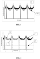
- FIG. 2 presents the method for detecting the first wheel revolution signal 3. From the first signal 1, here corrected to better explain the example, a threshold E is determined, illustrated by the dotted line 2. A series of increments I is identified when the first signal 1 crosses the dotted line 2, for example from below, which physically corresponds to an exit from the contact area by the sensor integrally connected in rotation to the pneumatic casing. The first wheel revolution signal 3 is then delimited between a first increment, here I 1 , and a second increment, here I 3 .
- the wheel revolution signal here represents the accelerometric signal from the sensor over two complete wheel revolutions.
- the threshold value E represented by the dotted line 2 was evaluated in our case on a part of the first signal 1 with a variable sampling frequency. On this part of the first signal 1, the discretized maximum value obtained, which is called MAX, is extracted. The threshold value E is then a value between 10 and 50% of the MAX value, in our case, this value is around 20%.
- the first reference acceleration ⁇ reference1 which is represented by the solid line 4 in black is calculated. Its evaluation is made in real time, by accumulating the values of the increments u of the first revolution signal which is divided at the end of the wheel revolution signal by the number of increments of the first wheel revolution signal.
- FIG. 3 is an illustration of the delimitation of the second wheel turn signal 7 in light gray from the first signal.
- This second wheel revolution signal 7 is subsequent to the first wheel revolution signal which ended at the increment I 3 .
- it is the first embodiment of this delimitation which is used.
- a threshold value E′ located, in our case, at half the first reference acceleration ⁇ reference1 is determined.
- a series of increments J is then identified on the first signal corresponding to the crossing of the first signal with respect to this threshold value E′.
- This threshold E' is illustrated by the dotted line 5.
- the second wheel revolution signal 7 is then delimited in gray using a first increment, here Ji, and a second increment, here J 3 .
- wheel revolution signal 7 corresponds to a finite number of wheel revolutions, here 2, up to discretization errors.
- the second reference acceleration ⁇ reference2 illustrated by the continuous line 6 is calculated as the average value of the second wheel revolution signal 7, in the same way as previously for ⁇ reference1 . This makes it possible to perform the calculation in real time at the level of the electronic component comprising the sensor while minimizing the memory and energy resources of the electronic component.
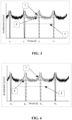
- FIG 4 is an illustration of the delimitation of the second wheel turn signal 7 in gray from the first signal.
- This second wheel revolution signal 7 is subsequent to the first wheel revolution signal which ended at the increment I 3 , which here is the increment K 1 .
- the first wheel revolution signal From the first wheel revolution signal, it is possible to calculate the period T of the first signal reduced to one wheel revolution.
- the first increment u of the first signal is identified which is situated between a quarter and three quarters of the period T located after the end of the first wheel revolution signal delimited by the increment K1.
- the second wheel spin signal begins shortly after halfway through the period. This physically corresponds to the instant when the sensor is located opposite the contact area defined by the pneumatic casing during its integral rotation with the pneumatic casing.
- a second wheel revolution signal 7 is then constructed in gray over a duration t corresponding to an integer multiple of the period T.
- the first increment u of the first signal located after the duration t of this second wheel revolution signal 7 will not be taken in the second wheel turn signal 7.
- a second reference acceleration ⁇ reference2 is determined as the average value of this second wheel revolution signal, represented by the continuous line 6.
- a series of increments K are defined from the last increment u having served to delimit the first wheel revolution signal.
- the first increment K 1 corresponds to the last increment u having served to delimit the end of the first wheel revolution signal. wheel.
- the other increments K are calculated using a threshold E' represented by the dotted line 5 which will be less than or equal to half of the first reference acceleration ⁇ reference1 defined on the first wheel revolution signal.
- FIG. 5 presents a first signal 1, previously corrected for the earth's gravity corresponding to the normal acceleration at the top of a pneumatic envelope of the heavy goods vehicle type rolling at a variable speed of rotation W.
- thresholds E and E′ are determined, represented by dotted lines 2 and 5, respectively for the first wheel revolution signal 3 in gray and the second wheel revolution signal 7 in light gray.
- the first threshold E makes it possible to identify the increments I corresponding for example to the exit from the contact area by the sensor.
- the first wheel revolution signal is limited to one wheel revolution, which is preferable for limiting the errors linked to the variation of the rotational speed W of the tire casing.
- the threshold E was chosen so that it corresponds to half of the reference acceleration of the first signal delimited over an integer number of wheel revolutions carried out before the first wheel revolution signal 3.
- the threshold E' for delimiting the second wheel revolution signal 7 here corresponds to half of the first reference acceleration ⁇ reference1 of the first wheel revolution signal.
- the second wheel revolution signal is delimited using these edges on a single wheel revolution.
- the second reference acceleration ⁇ reference2 is evaluated as the average value of this second wheel revolution signal 7, represented by the continuous curve 6.
- FIG. 6 is an illustration to explain the calculation of the positive S + and negative S - energy densities on a second wheel revolution signal 10 corresponds to a single revolution of the wheel when the rotational speed W is constant.
- the method is identical if the speed of rotation W is variable or if the wheel revolution signal is delimited over several wheel revolutions.
- the threshold A is determined as being here the product of a value C, here equal to 1.0, by the first reference acceleration ⁇ reference1 identified on the first wheel revolution signal.
- This threshold is materialized by the continuous line 11.
- a value of C of the order of 0.8 or 0.9 can be used. This value C must be fixed for all the steps of the method.
- the positive S + or negative S - energy densities are calculated as the sum of the absolute values of the differences between the second wheel revolution signal 10 and the first reference acceleration ⁇ reference1 , represented by the continuous curve 11. Necessarily, the surface bounded by the surfaces S + is equal to the surface bounded by the surface S -. except for discretization errors.
Landscapes
- Engineering & Computer Science (AREA)
- Mechanical Engineering (AREA)
- Measuring Fluid Pressure (AREA)
Claims (13)
- Verfahren zum Bestimmen der Verformung eines einer Last unterworfenen Reifenmantels in einem aufgeblasenen und mit einer Drehzahl W drehend belasteten Zustand, wobei der Reifenmantel einen Scheitel, zwei Flanken und zwei Wülste in einer Umdrehung um eine natürliche Drehachse und eine Mittelebene aufweist, wobei der Schnittpunkt der Mittelebene mit der natürlichen Drehachse einen Radmittelpunkt definiert, aufweisend die folgenden Schritte:- Befestigen mindestens eines Sensors an dem Reifenmantel direkt unter dem Scheitel mit einer radialen Position R in Bezug auf die natürliche Drehachse, die geeignet ist, mindestens ein Ausgangssignal proportional zu der von dem Sensor in dem Reifenmantel erfahrenen Beschleunigung zu erzeugen;- Durchführen der Erfassung eines ersten Abszissensignals u, das mindestens die Amplitude der Beschleunigung in der Normalenrichtung auf den Scheitel bei einem Fahren mit der Drehzahl W bei einer Abtastfrequenz fe aufweist, deren räumliche Diskretisierung kleiner als 6 Grad, vorzugsweise kleiner als 3 Grad, besonders bevorzugt kleiner als 1 Grad ist;- während einer ersten Phase:- Einfrieren einer ersten konstanten Abtastfrequenz fe1;- Begrenzen des ersten Signals auf eine ganze Zahl NTdR1 von Radumdrehungen, wobei NTdR1 größer oder gleich 1 ist, um ein erstes Radumdrehungssignal SigTdR1 zu bilden;- Ermitteln einer ersten Referenzbeschleunigung γreference1 als der Mittelwert des auf eine Radumdrehung zurückgeführten Radumdrehungssignals SigTdR1 gemäß der folgenden Formel:
 - wo NU1 die Anzahl an Punkten von SigTdR1 ist- während einer zweiten Phase:- Einfrieren einer zweite konstanten Abtastfrequenz fe2;- Begrenzen des ersten Signals auf eine ganze Zahl NTdR2 von Radumdrehungen, wobei NTaR2 größer oder gleich 1 ist, um ein zweites Radumdrehungssignal SigTaR2 zu bilden;- Definieren mindestens einer ersten Energiedichte S, die eine Funktion des zweiten Raddrehsignals SigTdR2, der Referenzbeschleunigung γreference1 ist, S+ genannt, wenn das Radumdrehungssignal größer als ein Schwellenwert A ist, oder S- genannt, wenn das Radumdrehungssignal kleiner oder gleich dem Schwellenwert A ist, gemäß den folgenden Formeln:
 - wo NU2 die Anzahl an Punkten von SigTdR2 ist- Identifizieren der durch die Last erzeugte Verformung des Reifenmantels Def% als eine Funktion der Referenzbeschleunigung γreference1 und der ersten Energiedichte S gemäß einer der folgenden Formeln:


- Verfahren zum Bestimmen der Verformung eines Reifenmantels nach Anspruch 1, bei dem die Erfassung des ersten Signals für eine Drehzahl W größer oder gleich einer Schwellendrehzahl Wseuil vorgenommen wird, die durch die folgende Formel definiert ist:
 - wo Dev die Entwicklung des Reifenmantels ist.
 - Verfahren zum Bestimmen der Verformung eines Reifenmantels nach einem der Ansprüche 1 bis 2, bei dem das Begrenzen des ersten Signals auf eine Zahl NTdR1 die folgenden Schritte aufweist:- während der ersten Phase:- Identifizieren einer ersten Reihe von Inkrementen I, die der Abszisse u des ersten Signals entsprechen, wo das erste Signal über oder unter einen Schwellenwert E gelangt;- Begrenzen des ersten Signals zwischen einem ersten Inkrement Imin und einem zweiten Inkrement Imax, um ein erstes Radumdrehungssignal SigTdR1 zu bilden;- Ermitteln der Anzahl an Radumdrehungen NTdR1 als die Differenz Imax minus Imin.
- Verfahren zum Bestimmen der Verformung eines Reifenmantels nach Anspruch 3, bei dem das Identifizieren der Schwelle E die folgenden Schritte aufweist:- vor der ersten Phase:- Festlegen einer Abtastfrequenz fe0 auf einen ersten Teil des ersten Signals;- Identifizieren des Maximalwerts MAX auf dem ersten Teil des ersten Signals;- Definieren eines Schwellenwerts E, der eine Funktion des Werts MAX ist; vorzugsweise liegt E zwischen 10% und 50% von MAX.
- Verfahren zum Bestimmen der Verformung eines Reifenmantels nach einem der Ansprüche 1 bis 4, bei dem das Begrenzen des ersten Signals auf eine Zahl NTdR2 die folgenden Schritte aufweist:- während der zweiten Phase:- Identifizieren einer ersten Reihe von Inkrementen J, die der Abszisse u des ersten Signals entsprechen, wo das erste Signal über oder unter einen Schwellenwert E' gelangt, vorzugsweise kleiner oder gleich der Hälfte der Referenzbeschleunigung Υreference1;- Begrenzen des ersten Signals zwischen einem ersten Inkrement Jmin und einem zweiten Inkrement Jmax um ein zweites Radumdrehungssignal SigTdR2 zu bilden;- Ermitteln der Anzahl an Radumdrehungen NTdR2 als Differenz Jmax minus Jmin.
- Verfahren zum Bestimmen der Verformung eines Reifenmantels nach einem der Ansprüche 1 bis 4, bei dem das Begrenzen des ersten Signals auf eine Zahl NTdR2 die folgenden Schritte aufweist:- während der ersten Phase:- Identifizieren der Periode T1 gemäß der folgenden Formel:
 - während der zweiten Phase;- Bilden eines zweiten Radumdrehungssignals SigTdR2, das mit der ersten Abszisse u des bei (1+M)/4 Perioden T1 gelegenen ersten Signals beginnt, wobei M eine positive reale Zahl kleiner oder gleich 2,0 ist, vorzugsweise ist M der Einheitswert, nach dem Ende des ersten Radumdrehungssignals SigTdR1;- Begrenzen des zweiten Radumdrehungssignals SigTdR2 über eine Dauer t2, die der Periode T1 multipliziert mit einer natürlichen ganzen Zahl N2 entspricht, vorzugsweise ist N2 der Einheitswert;- Die Anzahl an Radumdrehungen NTdR2 ist gleich N2;- Identifizieren einer ersten Reihe von Inkrementen K, die der Abszisse u des ersten Signals entsprechen, beginnend mit der Abszisse u, die zum Beenden des ersten Radumdrehungssignals SigTdR1 gedient hat, wo das erste Signal über oder unter einen Schwellenwert E' gelangt, der vorzugsweise kleiner oder gleich der Hälfte der Referenzbeschleunigung Υreference1 ist;- Ermitteln von N'U2 als die Anzahl an Punkten des ersten Signals:- die zwischen den Inkrementen K1 und Kn2+1 liegen, durch die Formel:
 - oder zwischen den Inkrementen K1 und Kn2+2liegen, durch die Formel:
- Verfahren zum Bestimmen der Verformung eines Reifenmantels nach einem der Ansprüche 1 bis 6, bei dem die Schwelle A zum Definieren der ersten Energiedichte eine Funktion der ersten Referenzbeschleunigung Υreference1 ist.
- Verfahren zum Bestimmen der Verformung eines Reifenmantels nach Anspruch 7, bei dem die Schwelle A zum Definieren der ersten Energiedichte eine Funktion eines Faktors C ist, der Faktor C größer oder gleich 0,5 und kleiner oder gleich 0,9 ist, gemäß der folgenden Formel:

- Verfahren zum Bestimmen der Verformung eines Reifenmantels nach einem der vorhergehenden Ansprüche, bei dem, nachdem das zweite Radumdrehungssignal SigTdR2 in Bezug auf eine Winkelposition des Reifenmantels abgestimmt wurde, eine Korrektur Corr an dem zweiten Radumdrehungssignal SigTdR2 vorgenommen wird, um die Wirkung der Erdschwerkraft zu berücksichtigen.
- Verfahren zum Bestimmen der Verformung eines Reifenmantels nach einem der Ansprüche 1 bis 9, bei dem das Identifizieren der Verformung des Reifenmantels Def% die folgenden Schritte aufweist:- während der zweiten Phase;- Ermitteln einer mit dem zweiten Radumdrehungssignal SigTdR2 verknüpften zweiten Referenzbeschleunigung γreference2, welche als der Mittelwert des auf eine Radumdrehung zurückgeführten zweiten Radumdrehungssignals SigTaR2 definiert ist, gemäß der folgenden Formel:
 - Identifizieren eines Werts O als der Wert NU2, außer wenn N'U2 existiert, dann ist der Wert O N'U2;- Identifizieren der durch die Last erzeugten Verformung des Reifenmantels Def% gemäß einer der folgenden Formeln:


- Verfahren zum Bestimmen der Verformung eines Reifenmantels nach einem der Ansprüche 1 bis 10, bei dem die Anzahl an Radumdrehungen NTdR2 des zweiten Radumdrehungssignals SigTdR2 der Einheitswert und die Anzahl an Radumdrehungen NTdR1 des ersten Radumdrehungssignals SigTdR2 der Einheitswert ist.
- Verfahren zum Bestimmen der Verformung eines Reifenmantels nach einem der Ansprüche 1 bis 11, bei dem, nachdem Ni Auswertungen, vorzugsweise ist Ni eine ganze Zahl zwischen 3 und 10, besonders bevorzugt 5, der Verformung des Reifenmantels Def% über unterschiedlichen ersten und zweiten Radumdrehungssignalen Sigi TdR1, Sigi TdR2 über demselben ersten Signal vorgenommen wurden, die Verformung des Reifenmantels Def% das Mittel der Verformungen des Reifenmantels Def% gemäß der folgenden Formel ist:

- Verfahren zum Bestimmen der Verformung eines Reifenmantels nach Anspruch 12, bei dem die Ni Auswertungen nacheinander so gemacht werden, dass die zweite Phase der Auswertung Ni die erste Phase der Auswertung Ni+1 ist.
Applications Claiming Priority (3)
| Application Number | Priority Date | Filing Date | Title |
|---|---|---|---|
| FR1873907 | 2018-12-21 | ||
| FR1900874A FR3092224A1 (fr) | 2019-01-30 | 2019-01-30 | Procédé d’obtention de la déformation d’un pneumatique sous charge en roulage |
| PCT/FR2019/053091 WO2020128278A1 (fr) | 2018-12-21 | 2019-12-16 | Procede d'obtention de la deformation d'un pneumatique sous charge en roulage |
Publications (2)
| Publication Number | Publication Date |
|---|---|
| EP3898286A1 EP3898286A1 (de) | 2021-10-27 |
| EP3898286B1 true EP3898286B1 (de) | 2023-02-08 |
Family
ID=69232870
Family Applications (1)
| Application Number | Title | Priority Date | Filing Date |
|---|---|---|---|
| EP19842823.7A Active EP3898286B1 (de) | 2018-12-21 | 2019-12-16 | Verfahren zur erhaltung der verformung eines unter belastung fahrenden reifens |
Country Status (4)
| Country | Link |
|---|---|
| US (1) | US12319100B2 (de) |
| EP (1) | EP3898286B1 (de) |
| KR (1) | KR102790011B1 (de) |
| WO (1) | WO2020128278A1 (de) |
Families Citing this family (7)
| Publication number | Priority date | Publication date | Assignee | Title |
|---|---|---|---|---|
| GB2565051A (en) * | 2017-07-27 | 2019-02-06 | Continental Automotive Gmbh | Method and device for monitoring a behavior of a tire of a vehicle |
| CN113195262B (zh) | 2018-12-21 | 2023-05-05 | 米其林集团总公司 | 用于在行驶期间获得负载下的轮胎的变形的方法 |
| FR3104491B1 (fr) | 2019-12-12 | 2021-12-24 | Michelin & Cie | Procédé d’obtention de la distance parcourue par un pneumatique en roulage |
| JP7700494B2 (ja) * | 2021-04-09 | 2025-07-01 | 住友ゴム工業株式会社 | タイヤ状態判定システム、タイヤ状態判定装置、タイヤ状態判定方法、及びプログラム |
| FR3126042B1 (fr) * | 2021-08-06 | 2023-07-21 | Michelin & Cie | Procédé d’obtention de la charge d’un pneumatique en roulage |
| EP4140782B1 (de) * | 2021-08-27 | 2025-12-10 | Bridgestone Europe NV/SA | Verfahren zur synchronisation der zeit eines reifenmontierten sensors mit dem strassenaufprall und zur messung der dauer und amplitude der aufstandsfläche |
| KR102608620B1 (ko) * | 2021-10-13 | 2023-12-04 | 넥센타이어 주식회사 | 타이어 정보 제어 방법 및 타이어 |
Family Cites Families (13)
| Publication number | Priority date | Publication date | Assignee | Title |
|---|---|---|---|---|
| US6142026A (en) * | 1994-06-06 | 2000-11-07 | Toyota Jidosha Kabushiki Kaisha | Wheel information estimating apparatus |
| US7081693B2 (en) * | 2002-03-07 | 2006-07-25 | Microstrain, Inc. | Energy harvesting for wireless sensor operation and data transmission |
| JP4917805B2 (ja) | 2003-10-31 | 2012-04-18 | ピレリ・タイヤ・ソチエタ・ペル・アツィオーニ | タイヤ転がり面の粗さを決定する方法及び装置 |
| DE602004012903T2 (de) | 2004-09-29 | 2009-04-09 | Pirelli Tyre S.P.A. | Verfahren und system zur bestimmung des schräglauf-winkels eines reifens während des fahrens eines fahrzeugs |
| BR112013014724A2 (pt) | 2010-12-23 | 2016-10-04 | Pirelli | método e sistema para estimar a carga que atua em um pneu |
| EP2665609A1 (de) | 2011-01-18 | 2013-11-27 | Barbalab S.r.l. | Vorrichtung zur überwachung des zustandes von radialer deformation eines reifens |
| DE102011000556A1 (de) | 2011-02-08 | 2012-08-09 | Continental Reifen Deutschland Gmbh | Verfahren zur Besprechung der Länger der Bodenaufstandsfläche eines rotierenden Fahrzeugreifens |
| DE102015216210A1 (de) | 2015-08-25 | 2017-03-02 | Continental Reifen Deutschland Gmbh | Verfahren zum Bestimmen von reifencharakteristischen Einflussgrößen, sowie Steuergerät hierfür |
| DE102016214865A1 (de) | 2016-08-10 | 2018-02-15 | Continental Automotive Gmbh | Elektronische Radeinheit für ein Fahrzeugrad, sowie Verfahren zum Betreiben einer derartigen elektronischen Radeinheit |
| JP7187214B2 (ja) * | 2018-08-28 | 2022-12-12 | 株式会社ブリヂストン | タイヤ状態検出システム、タイヤ状態検出方法及びタイヤ状態検出プログラム |
| US20210379954A1 (en) * | 2018-10-19 | 2021-12-09 | ClearMotion, Inc. | Method and apparatus for operating suspension systems |
| CN113195262B (zh) | 2018-12-21 | 2023-05-05 | 米其林集团总公司 | 用于在行驶期间获得负载下的轮胎的变形的方法 |
| FR3104491B1 (fr) | 2019-12-12 | 2021-12-24 | Michelin & Cie | Procédé d’obtention de la distance parcourue par un pneumatique en roulage |
-
2019
- 2019-12-16 US US17/416,950 patent/US12319100B2/en active Active
- 2019-12-16 KR KR1020217018856A patent/KR102790011B1/ko active Active
- 2019-12-16 WO PCT/FR2019/053091 patent/WO2020128278A1/fr not_active Ceased
- 2019-12-16 EP EP19842823.7A patent/EP3898286B1/de active Active
Also Published As
| Publication number | Publication date |
|---|---|
| KR102790011B1 (ko) | 2025-04-04 |
| KR20210104724A (ko) | 2021-08-25 |
| US20220080790A1 (en) | 2022-03-17 |
| US12319100B2 (en) | 2025-06-03 |
| EP3898286A1 (de) | 2021-10-27 |
| WO2020128278A1 (fr) | 2020-06-25 |
Similar Documents
| Publication | Publication Date | Title |
|---|---|---|
| EP3898286B1 (de) | Verfahren zur erhaltung der verformung eines unter belastung fahrenden reifens | |
| EP3898285B1 (de) | Verfahren zur erhaltung der verformung eines unter belastung fahrenden reifens | |
| EP3485299B1 (de) | Verfahren zur schätzung einer winkelabweichung zwischen der magnetischen achse und einer referenzachse eines magnetischen objekts | |
| WO2015082054A1 (fr) | Procede de determination de l'empreinte d'un pneumatique de roue sur le sol | |
| EP4072871B1 (de) | Feststellung der abgefahrenen distanz eines betriebenen reifen | |
| EP4084972B1 (de) | Verfahren zur festellung der belastung eines fahrenden reifens | |
| EP3898287B1 (de) | Verfahren zur feststellung der verformung eines unter belastung fahrenden reifens | |
| FR3092223A1 (fr) | Procédé d’obtention de la déformation d’un pneumatique sous charge en roulage | |
| FR3092224A1 (fr) | Procédé d’obtention de la déformation d’un pneumatique sous charge en roulage | |
| FR3092222A1 (fr) | Procédé d’obtention de la déformation d’un pneumatique sous charge en roulage | |
| EP4380804B1 (de) | Verfahren zur ermittlung der verformung eines reifens, der beim rollen einer belastung unterworfen wird | |
| EP4380805B1 (de) | Verfahren zur ermittlung der deformation eines reifens, der beim rollen einer äusseren spannung ausgesetzt ist | |
| EP4381267B1 (de) | Verfahren zur ermittlung der auf einen luftreifen ausgeübten last beim rollen | |
| WO2023012427A1 (fr) | Methode d'obtention d'un signal representatif de la deformation d'un pneumatique soumis a des forces externes en roulage |
Legal Events
| Date | Code | Title | Description |
|---|---|---|---|
| STAA | Information on the status of an ep patent application or granted ep patent |
Free format text: STATUS: UNKNOWN |
|
| STAA | Information on the status of an ep patent application or granted ep patent |
Free format text: STATUS: THE INTERNATIONAL PUBLICATION HAS BEEN MADE |
|
| PUAI | Public reference made under article 153(3) epc to a published international application that has entered the european phase |
Free format text: ORIGINAL CODE: 0009012 |
|
| STAA | Information on the status of an ep patent application or granted ep patent |
Free format text: STATUS: REQUEST FOR EXAMINATION WAS MADE |
|
| 17P | Request for examination filed |
Effective date: 20210721 |
|
| AK | Designated contracting states |
Kind code of ref document: A1 Designated state(s): AL AT BE BG CH CY CZ DE DK EE ES FI FR GB GR HR HU IE IS IT LI LT LU LV MC MK MT NL NO PL PT RO RS SE SI SK SM TR |
|
| DAV | Request for validation of the european patent (deleted) | ||
| DAX | Request for extension of the european patent (deleted) | ||
| GRAP | Despatch of communication of intention to grant a patent |
Free format text: ORIGINAL CODE: EPIDOSNIGR1 |
|
| STAA | Information on the status of an ep patent application or granted ep patent |
Free format text: STATUS: GRANT OF PATENT IS INTENDED |
|
| INTG | Intention to grant announced |
Effective date: 20220729 |
|
| GRAS | Grant fee paid |
Free format text: ORIGINAL CODE: EPIDOSNIGR3 |
|
| GRAA | (expected) grant |
Free format text: ORIGINAL CODE: 0009210 |
|
| STAA | Information on the status of an ep patent application or granted ep patent |
Free format text: STATUS: THE PATENT HAS BEEN GRANTED |
|
| AK | Designated contracting states |
Kind code of ref document: B1 Designated state(s): AL AT BE BG CH CY CZ DE DK EE ES FI FR GB GR HR HU IE IS IT LI LT LU LV MC MK MT NL NO PL PT RO RS SE SI SK SM TR |
|
| REG | Reference to a national code |
Ref country code: GB Ref legal event code: FG4D Free format text: NOT ENGLISH |
|
| REG | Reference to a national code |
Ref country code: CH Ref legal event code: EP Ref country code: AT Ref legal event code: REF Ref document number: 1547374 Country of ref document: AT Kind code of ref document: T Effective date: 20230215 |
|
| REG | Reference to a national code |
Ref country code: IE Ref legal event code: FG4D Free format text: LANGUAGE OF EP DOCUMENT: FRENCH |
|
| REG | Reference to a national code |
Ref country code: DE Ref legal event code: R096 Ref document number: 602019025166 Country of ref document: DE |
|
| REG | Reference to a national code |
Ref country code: NL Ref legal event code: FP |
|
| REG | Reference to a national code |
Ref country code: LT Ref legal event code: MG9D |
|
| REG | Reference to a national code |
Ref country code: AT Ref legal event code: MK05 Ref document number: 1547374 Country of ref document: AT Kind code of ref document: T Effective date: 20230208 |
|
| PG25 | Lapsed in a contracting state [announced via postgrant information from national office to epo] |
Ref country code: RS Free format text: LAPSE BECAUSE OF FAILURE TO SUBMIT A TRANSLATION OF THE DESCRIPTION OR TO PAY THE FEE WITHIN THE PRESCRIBED TIME-LIMIT Effective date: 20230208 Ref country code: PT Free format text: LAPSE BECAUSE OF FAILURE TO SUBMIT A TRANSLATION OF THE DESCRIPTION OR TO PAY THE FEE WITHIN THE PRESCRIBED TIME-LIMIT Effective date: 20230609 Ref country code: NO Free format text: LAPSE BECAUSE OF FAILURE TO SUBMIT A TRANSLATION OF THE DESCRIPTION OR TO PAY THE FEE WITHIN THE PRESCRIBED TIME-LIMIT Effective date: 20230508 Ref country code: LV Free format text: LAPSE BECAUSE OF FAILURE TO SUBMIT A TRANSLATION OF THE DESCRIPTION OR TO PAY THE FEE WITHIN THE PRESCRIBED TIME-LIMIT Effective date: 20230208 Ref country code: LT Free format text: LAPSE BECAUSE OF FAILURE TO SUBMIT A TRANSLATION OF THE DESCRIPTION OR TO PAY THE FEE WITHIN THE PRESCRIBED TIME-LIMIT Effective date: 20230208 Ref country code: HR Free format text: LAPSE BECAUSE OF FAILURE TO SUBMIT A TRANSLATION OF THE DESCRIPTION OR TO PAY THE FEE WITHIN THE PRESCRIBED TIME-LIMIT Effective date: 20230208 Ref country code: ES Free format text: LAPSE BECAUSE OF FAILURE TO SUBMIT A TRANSLATION OF THE DESCRIPTION OR TO PAY THE FEE WITHIN THE PRESCRIBED TIME-LIMIT Effective date: 20230208 Ref country code: AT Free format text: LAPSE BECAUSE OF FAILURE TO SUBMIT A TRANSLATION OF THE DESCRIPTION OR TO PAY THE FEE WITHIN THE PRESCRIBED TIME-LIMIT Effective date: 20230208 |
|
| PG25 | Lapsed in a contracting state [announced via postgrant information from national office to epo] |
Ref country code: SE Free format text: LAPSE BECAUSE OF FAILURE TO SUBMIT A TRANSLATION OF THE DESCRIPTION OR TO PAY THE FEE WITHIN THE PRESCRIBED TIME-LIMIT Effective date: 20230208 Ref country code: PL Free format text: LAPSE BECAUSE OF FAILURE TO SUBMIT A TRANSLATION OF THE DESCRIPTION OR TO PAY THE FEE WITHIN THE PRESCRIBED TIME-LIMIT Effective date: 20230208 Ref country code: IS Free format text: LAPSE BECAUSE OF FAILURE TO SUBMIT A TRANSLATION OF THE DESCRIPTION OR TO PAY THE FEE WITHIN THE PRESCRIBED TIME-LIMIT Effective date: 20230608 Ref country code: GR Free format text: LAPSE BECAUSE OF FAILURE TO SUBMIT A TRANSLATION OF THE DESCRIPTION OR TO PAY THE FEE WITHIN THE PRESCRIBED TIME-LIMIT Effective date: 20230509 Ref country code: FI Free format text: LAPSE BECAUSE OF FAILURE TO SUBMIT A TRANSLATION OF THE DESCRIPTION OR TO PAY THE FEE WITHIN THE PRESCRIBED TIME-LIMIT Effective date: 20230208 |
|
| PG25 | Lapsed in a contracting state [announced via postgrant information from national office to epo] |
Ref country code: SM Free format text: LAPSE BECAUSE OF FAILURE TO SUBMIT A TRANSLATION OF THE DESCRIPTION OR TO PAY THE FEE WITHIN THE PRESCRIBED TIME-LIMIT Effective date: 20230208 Ref country code: RO Free format text: LAPSE BECAUSE OF FAILURE TO SUBMIT A TRANSLATION OF THE DESCRIPTION OR TO PAY THE FEE WITHIN THE PRESCRIBED TIME-LIMIT Effective date: 20230208 Ref country code: EE Free format text: LAPSE BECAUSE OF FAILURE TO SUBMIT A TRANSLATION OF THE DESCRIPTION OR TO PAY THE FEE WITHIN THE PRESCRIBED TIME-LIMIT Effective date: 20230208 Ref country code: DK Free format text: LAPSE BECAUSE OF FAILURE TO SUBMIT A TRANSLATION OF THE DESCRIPTION OR TO PAY THE FEE WITHIN THE PRESCRIBED TIME-LIMIT Effective date: 20230208 Ref country code: CZ Free format text: LAPSE BECAUSE OF FAILURE TO SUBMIT A TRANSLATION OF THE DESCRIPTION OR TO PAY THE FEE WITHIN THE PRESCRIBED TIME-LIMIT Effective date: 20230208 |
|
| REG | Reference to a national code |
Ref country code: DE Ref legal event code: R097 Ref document number: 602019025166 Country of ref document: DE |
|
| PG25 | Lapsed in a contracting state [announced via postgrant information from national office to epo] |
Ref country code: SK Free format text: LAPSE BECAUSE OF FAILURE TO SUBMIT A TRANSLATION OF THE DESCRIPTION OR TO PAY THE FEE WITHIN THE PRESCRIBED TIME-LIMIT Effective date: 20230208 |
|
| PLBE | No opposition filed within time limit |
Free format text: ORIGINAL CODE: 0009261 |
|
| STAA | Information on the status of an ep patent application or granted ep patent |
Free format text: STATUS: NO OPPOSITION FILED WITHIN TIME LIMIT |
|
| 26N | No opposition filed |
Effective date: 20231109 |
|
| PG25 | Lapsed in a contracting state [announced via postgrant information from national office to epo] |
Ref country code: SI Free format text: LAPSE BECAUSE OF FAILURE TO SUBMIT A TRANSLATION OF THE DESCRIPTION OR TO PAY THE FEE WITHIN THE PRESCRIBED TIME-LIMIT Effective date: 20230208 |
|
| REG | Reference to a national code |
Ref country code: CH Ref legal event code: PL |
|
| PG25 | Lapsed in a contracting state [announced via postgrant information from national office to epo] |
Ref country code: LU Free format text: LAPSE BECAUSE OF NON-PAYMENT OF DUE FEES Effective date: 20231216 |
|
| PG25 | Lapsed in a contracting state [announced via postgrant information from national office to epo] |
Ref country code: MC Free format text: LAPSE BECAUSE OF FAILURE TO SUBMIT A TRANSLATION OF THE DESCRIPTION OR TO PAY THE FEE WITHIN THE PRESCRIBED TIME-LIMIT Effective date: 20230208 |
|
| GBPC | Gb: european patent ceased through non-payment of renewal fee |
Effective date: 20231216 |
|
| REG | Reference to a national code |
Ref country code: BE Ref legal event code: MM Effective date: 20231231 |
|
| PG25 | Lapsed in a contracting state [announced via postgrant information from national office to epo] |
Ref country code: MC Free format text: LAPSE BECAUSE OF FAILURE TO SUBMIT A TRANSLATION OF THE DESCRIPTION OR TO PAY THE FEE WITHIN THE PRESCRIBED TIME-LIMIT Effective date: 20230208 Ref country code: LU Free format text: LAPSE BECAUSE OF NON-PAYMENT OF DUE FEES Effective date: 20231216 |
|
| REG | Reference to a national code |
Ref country code: IE Ref legal event code: MM4A |
|
| PG25 | Lapsed in a contracting state [announced via postgrant information from national office to epo] |
Ref country code: IE Free format text: LAPSE BECAUSE OF NON-PAYMENT OF DUE FEES Effective date: 20231216 |
|
| PG25 | Lapsed in a contracting state [announced via postgrant information from national office to epo] |
Ref country code: GB Free format text: LAPSE BECAUSE OF NON-PAYMENT OF DUE FEES Effective date: 20231216 |
|
| PG25 | Lapsed in a contracting state [announced via postgrant information from national office to epo] |
Ref country code: BE Free format text: LAPSE BECAUSE OF NON-PAYMENT OF DUE FEES Effective date: 20231231 |
|
| PG25 | Lapsed in a contracting state [announced via postgrant information from national office to epo] |
Ref country code: CH Free format text: LAPSE BECAUSE OF NON-PAYMENT OF DUE FEES Effective date: 20231231 |
|
| PG25 | Lapsed in a contracting state [announced via postgrant information from national office to epo] |
Ref country code: IE Free format text: LAPSE BECAUSE OF NON-PAYMENT OF DUE FEES Effective date: 20231216 Ref country code: GB Free format text: LAPSE BECAUSE OF NON-PAYMENT OF DUE FEES Effective date: 20231216 Ref country code: CH Free format text: LAPSE BECAUSE OF NON-PAYMENT OF DUE FEES Effective date: 20231231 Ref country code: BE Free format text: LAPSE BECAUSE OF NON-PAYMENT OF DUE FEES Effective date: 20231231 |
|
| PG25 | Lapsed in a contracting state [announced via postgrant information from national office to epo] |
Ref country code: BG Free format text: LAPSE BECAUSE OF FAILURE TO SUBMIT A TRANSLATION OF THE DESCRIPTION OR TO PAY THE FEE WITHIN THE PRESCRIBED TIME-LIMIT Effective date: 20230208 |
|
| PG25 | Lapsed in a contracting state [announced via postgrant information from national office to epo] |
Ref country code: BG Free format text: LAPSE BECAUSE OF FAILURE TO SUBMIT A TRANSLATION OF THE DESCRIPTION OR TO PAY THE FEE WITHIN THE PRESCRIBED TIME-LIMIT Effective date: 20230208 |
|
| PG25 | Lapsed in a contracting state [announced via postgrant information from national office to epo] |
Ref country code: CY Free format text: LAPSE BECAUSE OF FAILURE TO SUBMIT A TRANSLATION OF THE DESCRIPTION OR TO PAY THE FEE WITHIN THE PRESCRIBED TIME-LIMIT; INVALID AB INITIO Effective date: 20191216 |
|
| PG25 | Lapsed in a contracting state [announced via postgrant information from national office to epo] |
Ref country code: HU Free format text: LAPSE BECAUSE OF FAILURE TO SUBMIT A TRANSLATION OF THE DESCRIPTION OR TO PAY THE FEE WITHIN THE PRESCRIBED TIME-LIMIT; INVALID AB INITIO Effective date: 20191216 |
|
| PG25 | Lapsed in a contracting state [announced via postgrant information from national office to epo] |
Ref country code: TR Free format text: LAPSE BECAUSE OF FAILURE TO SUBMIT A TRANSLATION OF THE DESCRIPTION OR TO PAY THE FEE WITHIN THE PRESCRIBED TIME-LIMIT Effective date: 20230208 |
|
| PGFP | Annual fee paid to national office [announced via postgrant information from national office to epo] |
Ref country code: DE Payment date: 20251211 Year of fee payment: 7 |
|
| PGFP | Annual fee paid to national office [announced via postgrant information from national office to epo] |
Ref country code: IT Payment date: 20251223 Year of fee payment: 7 |
|
| PGFP | Annual fee paid to national office [announced via postgrant information from national office to epo] |
Ref country code: NL Payment date: 20251219 Year of fee payment: 7 Ref country code: FR Payment date: 20251229 Year of fee payment: 7 |