EP2903744B1 - Procédé et dispositif de traitement et de séparation d'un matériau à partir d'un système contenant plusieurs substances liées - Google Patents
Procédé et dispositif de traitement et de séparation d'un matériau à partir d'un système contenant plusieurs substances liées Download PDFInfo
- Publication number
- EP2903744B1 EP2903744B1 EP14712271.7A EP14712271A EP2903744B1 EP 2903744 B1 EP2903744 B1 EP 2903744B1 EP 14712271 A EP14712271 A EP 14712271A EP 2903744 B1 EP2903744 B1 EP 2903744B1
- Authority
- EP
- European Patent Office
- Prior art keywords
- grinding
- bed
- rollers
- roller mill
- sand
- Prior art date
- Legal status (The legal status is an assumption and is not a legal conclusion. Google has not performed a legal analysis and makes no representation as to the accuracy of the status listed.)
- Active
Links
Images

Classifications
-
- B—PERFORMING OPERATIONS; TRANSPORTING
- B02—CRUSHING, PULVERISING, OR DISINTEGRATING; PREPARATORY TREATMENT OF GRAIN FOR MILLING
- B02C—CRUSHING, PULVERISING, OR DISINTEGRATING IN GENERAL; MILLING GRAIN
- B02C25/00—Control arrangements specially adapted for crushing or disintegrating
-
- B—PERFORMING OPERATIONS; TRANSPORTING
- B02—CRUSHING, PULVERISING, OR DISINTEGRATING; PREPARATORY TREATMENT OF GRAIN FOR MILLING
- B02C—CRUSHING, PULVERISING, OR DISINTEGRATING IN GENERAL; MILLING GRAIN
- B02C15/00—Disintegrating by milling members in the form of rollers or balls co-operating with rings or discs
- B02C15/04—Mills with pressed pendularly-mounted rollers, e.g. spring pressed
-
- B—PERFORMING OPERATIONS; TRANSPORTING
- B02—CRUSHING, PULVERISING, OR DISINTEGRATING; PREPARATORY TREATMENT OF GRAIN FOR MILLING
- B02C—CRUSHING, PULVERISING, OR DISINTEGRATING IN GENERAL; MILLING GRAIN
- B02C4/00—Crushing or disintegrating by roller mills
Definitions
- the invention relates to a method for processing and separating a material from a bonded multi-fuel system as well as a vertical roller mill for carrying out this method.
- a separating device is known in order to crush concrete fracture and, if possible, in this case also to be able to recover the individual components of the concrete.
- the desired levels of purity of the individual recycled components such as gravel and sand can not be achieved or only under particularly favorable circumstances.
- roller mills which are actually pure comminution units, are used for the treatment and separation of materials.
- Such a method is for example from the WO 2011/107124 A1 known.
- stainless steel slags which consist of a silicate fraction and a metal fraction, are selectively comminuted and separated from one another.
- It is essential in this method to continue to use the mill primarily as a crushing unit and to significantly reduce the abandoned raw materials, and only to achieve a separation as a secondary downstream property.
- the necessary pressure-related comminution can be achieved with this method, a separation only if one of the components to be separated is ductile, so that it is not crushed during the grinding process.
- the separation is made by crushing one component by the roller pressure while not crushing another one. This is possible because the component not to be shredded has ductile properties. At a slightly too high grinding pressure, this component deformed, which is unintentional, but it is still not crushed.
- This object is achieved by a method for processing and separating a material from an associated multi-component system with the features of claim 1 and a vertical roller mill with the features of claim 13.
- a grinding bed of machined and machined material is formed on the grinding bowl, on which the grinding rolls roll.
- the material is separated into the first and second components by shearing and attrition of the particles of the components by means of grinding rollers in the grinding bed, wherein the particles of the first component, the particles of the second component and particles of the same component mutually attritiert become.
- the contact pressure is chosen so that directly by the surface pressure directly essentially no pressure-induced comminution of the first and / or second component is performed.
- the preparation of the material takes place essentially only by the attrition of the material or of the particles of the first and / or second component mutually. A pressure-related crushing is not provided. If a comminution is carried out, this is done mainly by the mutual rubbing of the material.
- the roller mill is operated such that the grinding bed has a minimum height which is greater than the diameter of the particles of one of the two components. Subsequent to the in-bed attrition or the machining in the grinding bed, at least the first and the second component are removed from the processing circuit of the roller mill and sorted.
- a basic idea of the method according to the invention can be seen in using a roller mill, in particular a vertical roller mill, no longer as a comminution unit, in which the material to be comminuted is "crushed" by the pressure of the rollers, but the roller mill, in particular that formed on the roller mill Mahlbett, for the separation and processing of the feed material into its components, in particular in the first and second components to use.
- This separation and processing of the feed material takes place within the grinding bed by mutual rubbing stress, that is, attrition of the material.
- Another basic idea on which the invention is based is to design the grinding bed such that it has a minimum height, which is greater than the diameter of the particles of one of the two components.
- the harder or tougher of the two components of the joined multi-component system is selected.
- This design of the grinding bed ensures that the harder component is not comminuted by the roller pressure.
- it does not necessarily have to be the hardest of the components.
- the Mahlbett Turner is at least as high as the average size of one of the components. In this way, it is ensured with sufficient likelihood that during the preparation process it does not come to a pressure-related comminution but essentially to the preparation or comminution due to attrition processes in the grinding bed, that is to say rubbing comminution.
- the connected multicomponent system may also consist of more than the two components exemplified here.
- the better cohesive component As a harder component can be understood in the context of the invention, the better cohesive component.
- the inventively selected contact pressure of the rolls which can be alternatively referred to as grinding rollers is selected so that a surface pressure in the range of 15 kN / m 2 to a maximum of 140 kN / m 2 occurs.
- the contact pressure depends, among other things, on the size of the rolls, the size of the vertical mill and / or the weight of the rolls.
- the reference pressure used here is the surface pressure, so that a guide size is available irrespective of the size of the rollers or mill.
- the preferred range of the surface pressure depends on the materials to be processed, wherein the surface pressure is chosen so that there is essentially no pressure-related comminution of the material to be ground.
- the invention is further based on the surprising finding that, despite the fact that the surface pressure is actually too low for the operation of a roller mill, it is possible to machine the material to be charged. This is essentially due to the fact that, in contrast to the previous operating mode of the mill, no actual grinding takes place, but the materials essentially process one another and are not processed by the rollers. This even leads to the fact that with the inventive method, a treatment and separation of materials is possible whose components have substantially no density differences.
- the contact pressure is chosen such that, in the case of in-bed attrition, shearing forces between the particles are in the range from 5 kN / m 2 to 70 kN / m 2 , in particular between 7 kN / m 2 and 20 kN / m 2 ,
- the ranges given for the shear forces between the particles of the various components of the bonded multi-material system allow good attrition in the grinding bed, so that the processing and separation of the bonded multi-component system can be carried out in the mill. This can be achieved by the existing shear forces and a sufficiently large purity of the individual components with each other, without risking excessive crushing.
- One component that is essential in adjusting the shear forces is the contact force of the rollers. This should ideally be adjusted so that the desired shear forces occur in the grinding bed by the rotation of the grinding table in combination with the rollers and the rotation of the rollers.
- different shear or friction forces act on the material to be processed: On the one hand, the shear and frictional forces of the individual material particles with one another; on the other hand, the shear forces that are applied to the material via the rollers.
- the generation of shear forces is essentially due to the velocity of the particles passing under the mill compared to the peripheral speed of the roller passing the particles or past the particles.
- the grinding bed preferably has a maximum height of 8% of the grinding bowl diameter, but preferably about 4% of the grinding bowl diameter.
- the grinding gap that is, the distance between the grinding rollers and the grinding table or the grinding bowl, is not too large, so that the forces introduced by the grinding rollers in the grinding bed forces can be actively used for crushing the ground material.
- the grinding gap is too large, it may happen on the one hand that the material to be ground is in some cases only compacted and thus no sufficient pressure is applied to the material to be ground, and on the other hand that the material to be ground flows out of the grinding gap, so that it displaces but does not break up becomes.
- the Mahlbettiere can be adjusted by means of the contact pressure of the rollers, a feed mass flow, a Mahlschüsselformatbaum, a height of a storage edge of the grinding bowl and / or an internal circulation flow.
- Another parameter that can be used to set the grinding bed height is the internal circulation flow. These are, in particular in roller mills with integrated sifter, the amount of particles which are rejected during the sighting and are returned to the grinding bowl for further processing. If the internal circulation flow is increased, the grinding bed height also increases.
- the internal circulation flow can be influenced for example by means of the classifier settings as well as by means of the volume of the process air flow.
- the material binding of the multicomponent system is increased, to increase the contact pressure, in order to achieve the necessary forces for in-bed attrition despite the increased material binding.
- the Mahlbettiere should be kept the same, other parameters must be adjusted because the Mahlbettiere is initially reduced by the increased contact pressure. In this case, it is preferable to increase the feed mass flow and / or the inner circulation flow. Alternatively or additionally, the Mahlschüsselwindiere can be reduced. The setting of these parameters is also possible during operation, so that if it is found, for example, in tests that the material binding of the multi-component system is higher than before, it can be responded to by the parameters specified here.
- Another option is to increase the height of the storage area. However, this is not or only with difficulty possible during operation, so that this variation is mainly used when the roller mill used is to be switched to another multicomponent system or designed for this.
- the mass flow rate is increased in order to increase the throughput, it is advantageous if, in particular, the grinding bowl rotational speed is increased in order to maintain the grinding bed height.
- Increasing the contact force of the rolls would also reduce the millbase height, but this would lead to a change in the in-bed attrition variables.
- the higher pressure force of the rollers would increase the grinding pressure, that is to say the force which is introduced into the grinding bed by means of the rollers, as a result of which the surface pressure also increases. This can lead to a poorer treatment and separation of the multicomponent system.
- the rolling mill is operated at startup with a higher contact pressure of the rollers than the contact force selected during operation. This is necessary in order to initially set the rollers, which have a starting torque to be overcome, in rotation. Subsequently, during in-bed attrition operation, the friction between the grinding bed and grinding rolls is usually sufficient to maintain the rotation of the rolls.
- the rotation of the rollers is monitored during operation, and the pressing force of the rollers is at least temporarily increased if too little rotation of the rollers is detected. Too low a rotation of the rolls causes the shear forces introduced by the rolls into the grinding bed to change and thus the quality of the in-bed attrition also changes. Due to the short-term increase in the contact force of the rollers is achieved that they have a sufficient rotation or a sufficient angular momentum. For the purposes of the invention, too little rotation of the rollers is understood when the peripheral speed of the roller is less than 50% of the speed of the material flow under the roller.
- the roller bearings are designed with a larger game than conventionally. On the one hand, this reduces the starting torque and, on the other hand, also reduces the risk of stoppage or of the grinding rollers having too low a rotational speed.
- the roller mill is operated in an overflow and / or air flow mode.
- the prepared ground material is conveyed, inter alia, by the rotation of the grinding bowl over a possibly existing storage area and falls into an area below the grinding bowl. Here it can be transported away.
- the grinding stock falling over the grinding table is picked up by means of a process air flow and in particular blown away upwards.
- Above the grinding bowl is usually a sifter to which the prepared ground material is transported by means of the process air stream.
- a sighting takes place, so that sufficiently finely prepared ground material is withdrawn from the preparation process, whereas further to be processed ground material is fed back to the reprocessing process as a so-called reject.
- in-bed attrition is also referred to as a milling process in the context of the invention, as it may be considered as being distantly related to standard milling processes, but differs therefrom by another shredding technique.
- the in-bed attrition is carried out by means of a roller mill, so that the terminology for mills is used for ease of understanding, although in the true sense, grinding no longer takes place.
- the process air stream that passes around the grinding bowl does not absorb all the overflowing regrind, but only a portion thereof. Another part falls down and is transported by means of subsidy from below the grinding bowl.
- the material to be processed and separated from the connected multi-component system concrete fracture is concrete fracture itself consists mostly of gravel, sand and cement.
- gravel and sand are separated from one another and from the cement stone by means of the in-bed attrition and cleaned. Due to the in-bed attrition, the cement stone in particular is rubbed off by the gravel and sand, so that, according to the method according to the invention, gravel and sand are again essentially in pure form and can thus be used again for the production of concrete.
- a vertical roller mill with separator which can also be integrated, is used. additionally a process air stream is adjusted so that from the overflowing millbase a component, such as cement paste, and at least partially compounds of the first and the second component, such as cement stone and sand, are transported by means of the process air flow to the classifier, while the first purified component, such as gravel and sand, are removed as coarse material from the grinding process.
- a component such as cement paste
- the first and the second component such as cement stone and sand
- the shredded second component such as comminuted cement stone
- the first and the second component such as cement stones and Compounds made of cement stones and sand
- sand can be separated from the coarse material withdrawn by sieving, so as to enable further separation in multi-component systems comprising more than two components.
- a vertical roller mill is operated in the combined overflow and air flow mode.
- the process air stream which sweeps from below around the grinding bowl, adjusted so that it only light or small materials, especially crushed cement stone and adhesions of cement stone and sand, transported upwards towards the sifter.
- Cleaned heavy components such as sand and gravel can fall down against the process stream and be removed as coarse material from the grinding process.
- fused material which is also called intergrown, can be discharged from the components such as gravel, sand and cement stone as coarse material from the grinding process. This insufficiently processed material can be detected by sorting processes and fed back to the in-bed attrition method according to the invention.
- a subsequent separation by sieving is suitable.
- the material brought to the classifier with the process air stream is sighted there.
- only crushed cement paste is discharged as fine material, whereas the remaining material is fed back to the grinding bowl.
- the comminution of the cement stone takes place accordingly the process of the invention essentially not by a compressive stress but by the in-bed attrition instead.
- the cement is crushed by the other particles as well as other cement stones.
- the inventive method may preferably with a roller mill with a rotatable grinding bowl, on the operation of a grinding bed is made of ground material and with at least two stationary, rotatable grinding rollers, which roll on the ground during operation run.
- a sifter is preferably arranged above the grinding rollers and additionally provided a device for defining and maintaining a minimum grinding gap between the grinding bowl and the grinding rollers.
- the vertical roller mill according to the invention is based on the finding that in the case of in-bed attrition a significantly lower compression of the ground material on the grinding bed is necessary, or may occur, than with a conventional grinding bed, which is present, for example, during coal grinding. Due to this low compression or force through the grinding rollers, however, there is a problem in connection with locally different hardnesses and other properties of the grinding bed, which can be significantly different pronounced. For example, in some places due to the low compression and relatively high height of the grinding bed more air bubbles may be present than at others. Now, if the grinding rollers operated with a constant contact pressure, so there is a risk that at the points where more air bubbles are present, the grinding rollers squeeze the grinding bed much stronger than at others.
- corresponding stops or stop buffers may be provided for the grinding rollers.
- Another possibility is to design the hydraulic system of the grinding rollers accordingly.
- a hydraulic system for adjusting the contact force of the grinding rollers in operation counteracting the weight of the grinding rollers to a surface pressure in the range of 15 kN / m 2 to 140 kN / m 2 relative to the vertically projected area of the mean roller diameter to enable.
- the hydraulic system is designed in vertical roller mills, in particular the LOESCHE type, such that the pressing force of the grinding rollers acts in the same direction as the weight force.
- a surface pressure of 600 kN / m 2 up to 1000 kN / m 2 or more should be achieved by means of the hydraulic system. In the case of in-bed attrition, however, this is not desired.
- a monitoring system is provided on each grinding roller, which monitors the rotation of the grinding rollers during operation. This is necessary when using a vertical roller mill for in-bed Attrition, as already worked with a very low contact pressure, so that it may happen that the grinding rollers do not rotate sufficiently.
- this state can be detected and appropriate countermeasures can be triggered, for example, the temporary increase of the contact force can be performed.
- Fig. 1 is shown as an example of the inventive method for processing and separating a material from a connected multi-fuel system, a flow chart 10 for concrete fracture treatment.
- the method for treating concrete fracture described in more detail below can also be used in the same or similar manner for other material systems in which the individual components have no ductile properties.
- the following embodiment is merely exemplary in order to clarify the exact embodiment of the method according to the invention and its advantages by way of examples.
- the individual method steps, which are described in a coherent manner in this example can also be carried out individually and are thus to be considered separately as part of the invention.
- concrete granules having a size of, for example, up to 80 mm grit size are used as starting material or feed product 11.
- This concrete granulate which is also referred to as concrete fracture, is given to a roller mill 12 according to the invention as a feedstock.
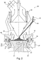
- the roller mill 12 is in the process after Fig. 1 operated in combined overflow and air flow mode and is also referred to as a vertical roller mill. The processes occurring in the roller mill 12 and the operation of the roller mill 12 will be described later with reference to FIG Fig. 2 detailed.
- the roller mill 12 is operated according to the invention as an in-bed Attritionsaggregat and not as a crushing unit.
- processed and crushed cement stone 16 are withdrawn from the treatment cycle.
- coarse material 13 which consists essentially of processed gravel, sand and still fused material, the proportion of which, however, is significantly lower than the feed material 11. In the intergrown material this may be in particular gravel and / or act sand with adhesions of cement stone.
- the coarse material 13 is subjected to a screening 14, with which the sand 17 can be removed as a fraction of 0 mm to 2 mm. This sand 17 is so well cleaned by the inventive method 10 that it can be used similar to primary sand in concrete production.
- the coarse material 13 which has a size of over 2 mm, is then subjected to a density sorting 15. This serves to be able to discharge cleaned gravel 18, which has a higher density, out of the processing circuit. Material which does not have a sufficiently high density - this is in particular Gravel and / or sand, on which cementum stone adhesions are still present, are again supplied to the in-bed attrition in the roller mill 12.
- the procedure is conceivable, but not shown here, that the sand is also fed to a density sorting, in order to possibly also remove there any remaining adhesions to cement paste or other impurities and to feed it again to the rolling mill process.
- the density sorting can be done as a dry density sorting, for example by means of air classifier, air mesh machines and / or air fluidized bed sorting.
- a wet density sorting can be performed. In this case, however, then the rolling mill 12 again supplied materials must be dried again.
- a wet sorting method for example, floating-sink divorce, both static and dynamic, setting sorting, Wendelscheider- or herdsortierung and Wirbel harshsortier processor possible.
- FIG. 2 is a schematic sectional view through a vertical roller mill 30 of the LOESCHE type shown.
- An essential part of the roller mill 30 are frusto-conical grinding rollers 31, which roll on a grinding bed 41.
- frusto-conical grinding rollers 31 which roll on a grinding bed 41.
- vertical rolling mills 30 having three, four, six or more grinding rolls may also be used.
- the grinding bed 41 is formed on a grinding bowl 32.
- the grinding rollers 31 themselves, which may alternatively be referred to as rollers, are provided fixed, but rotatable about the drawn axis.
- the grinding bowl 32 in turn is rotatable about its central axis as indicated. Will now the grinding bowl Turned 32, so the existing on the grinding bed regrind 42 also rotates. As a result, the grinding rollers 31 are rotated by friction between the ground material 42 and the outer contour of the grinding rollers 31 in rotation.
- a separator 34 which can be designed both dynamically and statically, is provided.
- the in-bed attrition process according to the invention will now be discussed in more detail.
- the feedstock or ground material 42 for example concrete fracture, is fed to the preparation process via a material feed 35.
- the material task 35 is designed such that the feedstock 42 is abandoned in the central region of the grinding bowl 32.
- the material to be ground is accelerated on the one hand and, on the other hand, transported spirally outwards, so that it is rolled over by the grinding rolls 31.
- the grinding rollers 31 are operated in a manner different from that normally used in roller mill 30. They are essentially not used here for pressure reduction of the ground material.
- only a very small surface pressure is applied to the grinding bed 41 by the grinding rollers 31. This is in the range of 15 kN / m 2 to a maximum of 140 kN / m 2 . It is preferably in the range between 30 kN / m 2 and 80 kN / m 2 .
- This surface pressure essentially serves to introduce sufficiently large shear forces into the grinding bed 41, so that the particles present therebetween attritieren each other.
- grinding rolls have a mean diameter of up to 2.8 m and weigh up to 45 t. With this high weight, a much higher surface pressure would be achieved than that to which the in-bed attrition is maximally possible. For this reason, an in Fig. 2 not shown inverse hydraulic system provided, which serves to counteract the weight of the rollers 31.
- This hydraulic system can act as a negative force on a rocker arm 33 of the grinding rollers 31. In other words, the inverse hydraulic system pushes on the pivot lever 33, that the roller 31 is slightly raised or acting on the roller a force against its weight.
- the material located on the grinding bowl 32 which is already partially processed, displaced and runs over a storage edge 36 in a gap between Grinding bowl 32 and mill housing over.
- the amount of the supplied process air 37 is essential for the first sighting.
- the sighting can also be influenced by a blade ring 38.
- the process air 37 is set in combination with the blade ring 38 such that substantially overflowing coarse material 51 gravel and sand from the processing cycle can be deducted. This will then, as with respect to Fig. 1 described, subjected to a screening.
- the injected process air 37 carries in particular crushed cement stone as well as particles of sand with adhesive cement stone to prepare for shipment. There takes place a second sighting. Again, this is a density sorting.
- Not sufficiently crushed cement stone or fused cement stone and sand material is passed through a semolina cone 40 back to the grinding bowl 32 and there fed to a further in-bed Attrition.
- roller speed meter 46 are provided which determine the rotational speed of the rollers 31 during operation. This is necessary because it may happen that the rollers rotate too slowly due to the low contact pressure at which the rollers 31 are pressed onto the grinding bed during in-bed attrition. If this is detected by means of the roller speed meter 46, the contact force can be temporarily increased so as to increase the rotation of the rollers.
- Essential for the method according to the invention and the successful in-bed attrition is to make the grinding bed sufficiently high so that sufficient particles of the feed material are present, so that a mutual attrition is made possible.
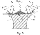
- Possible influencing variables for the grinding bed are described below in Fig. 3 explained in more detail.
- Fig. 3 is a section of the roller mill 30 from Fig. 2 shown.
- the same reference numerals as in Fig. 2 used further.
- the height h of the ram edge 36 and the inner recycle stream are substantially the task mass flow ⁇ m, in which pressing force F W to the grinding rolls 31, the Mahlschüsselformatiere n S, is available.
- the internal circulation stream is here in Fig. 3 not shown. It is essentially material rejected by the sifter, which constitutes part of the feed mass flow ⁇ m, in .
- the Mahlbett shoulders s can be varied by a variation of the contact pressure F W of the rollers 31, which influences the surface pressure.
- the surface pressure is the force acting directly below the rollers on the grinding bed. If the contact pressure F W of the rolls is increased, then the millbase is more compacted or comminuted, so that the Mahlbett Americans s decreases. Conversely, the Mahlbettiere Americans s increases when the rollers 31 are pressed with a lower contact force F W on the grinding bed 41.
- Influence of the feed mass flow ⁇ m in can be done in two ways.
- the roller mill 30 can be given more feed material per unit of time; on the other hand, the separator can be set differently, so that a higher reject, ie a higher rejection on the separator, is present, so that more material is fed back to the grinding bowl 32 becomes.
- the reject can also be increased by increasing the process air flow, as in this case less regrind down than coarse material is withdrawn from the processing cycle, but instead is transported as a potential fines to the classifier.
- the feed mass flow ⁇ m, in as well as the inner circulation flow significantly influence the discharge mass flow ⁇ m, out . If the internal circulation flow is increased, it is said that the circulating load is increased.
- Mahlbettiere Another way to vary the Mahlbettiere is to increase the bowl speed n S. If this is increased, the grinding bed height s decreases. By a higher Mahlschüsselformatiere n S , the residence time of the material to be processed on the grinding bowl 32 is reduced. Accordingly, the mass flow ⁇ m, on the grinding bowl is lower. This forcibly reduces the Mahlbett seats s.
- the storage area 36 Another possibility to influence the Mahlbettiere too s, is the storage area 36. If its height h increased so accumulates more material on the grinding table. This means that in principle more material has to be present on the grinding bowl 32 so that it can flow out of the grinding bowl 32 with the discharge mass flow ⁇ m, out .
- the method according to the invention can also be used for the preparation and separation of many different connected multicomponent systems.
- the in-bed attrition in the roller mill which in other words allows only a frictional stress of the material to be processed and not actual comminution
- natural shale which from slate and impurities such as lime, ores or other organic components exists to be used.
- the method is suitable for processing mica, which consists of phyllosilicates and possible impurities.
- mica which consists of phyllosilicates and possible impurities.
- impurities mainly pure deposits are exploited until now.
- this is only the case since no suitable treatment methods for dry attrition and separation have been known hitherto.
- the process according to the invention can be used in the treatment of kaolin-containing industrial sands, which consist of kaolin, feldspar and quartz sand.
- kaolin-containing industrial sands which consist of kaolin, feldspar and quartz sand.
- graphite ore which consists of graphite and ore matrices, and of clay or bentonite, contaminated by sand or non-layered silicates, as well as the digestion by attrition of heavy mineral sands for the separation of cohesive constituents and subsequent density separation of rutile, zirconium, ilmenite , etc. of an unsatisfied sandy fraction with the method according to the invention possible.
- Even FeCr slags consisting of disintegrating slag, corresponding metal and possibly stabilized slags can be treated.
- the metal component is a non-ductile component, since otherwise attrition according to the method according to the invention is not possible, since otherwise no frictional stress in the sense of the
Claims (14)
- Procédé de traitement et de séparation d'un matériau à partir d'un système comprenant plusieurs substances liées,
tandis que le système comprenant plusieurs substances liées est composé d'au moins un premier composant et d'un deuxième composant qui est lié au premier composant, et tandis que les deux composants ne présentent aucune propriété ductile,
tandis que le matériau est introduit en tant que produit entrant (42) dans un broyeur à rouleaux (30) avec un récipient de broyage (32) et des rouleaux broyeurs (31) en vue d'une attrition en lit (42),
tandis que se forme sur le récipient de broyage (32) en fonctionnement un lit de broyage (41) composé d'un matériau traité et à traiter,
tandis que les rouleaux broyeurs (31) en fonctionnement roulent sur le lit de broyage (41),
tandis que, lors de l'attrition en lit, le matériau est séparé, au moyen des rouleaux de broyage (31) dans le lit de broyage (41), par le biais de cisaillement et de frottement des particules des composants entre eux, dans le premier composant et dans le deuxième composant, tandis que les particules du premier composant, les particules du deuxième composant et les particules d'un même composant sont mutuellement attriter,
tandis que pour l'attrition en lit, le broyeur à rouleaux (30) ne fonctionne qu'avec une force de pressage (FW) des rouleaux de broyage (31), pour atteindre un pressage de surface dans un domaine allant de 15 kN/m2 à 140 kN/m2, se rapportant à la surface projetée verticalement du diamètre moyen des rouleaux, laquelle est choisie de sorte à ce qu'en raison du pressage de surface, pour l'essentiel aucune concussion du premier et/ou du deuxième composant due à la pression ne se produise directement,
tandis que le broyeur à rouleaux (30) fonctionne de telle sorte que le lit de broyage (41) présente une hauteur minimale qui est plus élevée que le diamètre des particules de l'un des deux composants, et
tandis qu'au moins le premier composant et le deuxième composant sont retirés d'un circuit de traitement du broyeur à rouleaux (30) et triés. - Procédé selon la revendication 1,
caractérisé en ce que
la force de pressage est sélectionnée de telle sorte que la force de cisaillement générée lors de l'attrition en lit entre les particules se situe dans le domaine allant de 5 kN/m2 à 70 kN/m2 et plus particulièrement dans le domaine allant de 7 kN/m2 à 20 kN/m2. - Procédé selon la revendication 1 ou 2,
caractérisé en ce que
la hauteur du lit de broyage (s) est réglée à maximum 8 % du diamètre du récipient de broyage. - Procédé selon les revendications 1 à 3,
caractérisé en ce que
la hauteur du lit de broyage (s) est réglée à environ 4 % du diamètre du récipient de broyage. - Procédé selon une des revendications 1 à 4,
caractérisé en ce que
pour une force de pressage (Fw) nécessaire, la hauteur du lit de broyage (s) est réglée au moyen d'un flux massique entrant (mm,in), un nombre de tours du récipient de broyage (ns), une hauteur (h) d'un rebord d'encombrement du récipient de broyage (31) et/ou d'un courant de circulation interne. - Procédé selon l'une des revendications 1 à 4,
caractérisé en ce que
en cas d'augmentation de la liaison des substances du système comprenant plusieurs substances, la force de pressage (Fw) est augmentée pour atteindre l'attrition en lit, tandis que, pour maintenir une hauteur de lit de broyage (s), le flux massique entrant (mm,in) est augmenté, la hauteur (h) du rebord d'encombrement est augmentée, le courant de circulation interne est augmenté et/ou le nombre de tours du récipient de broyage (ns) est réduit. - Procédé selon une des revendications 1 à 6,
caractérisé en ce que
pour augmenter le débit, le flux massique entrant (mm,in) est augmenté, tandis que, pour maintenir une hauteur de lit de broyage (s), le nombre de tours du récipient de broyage (ns) est augmenté. - Procédé selon une des revendications 1 à 7,
caractérisé en ce que
le broyeur à rouleaux (30), au démarrage, est mis en fonctionnement avec une force de pressage (Fw) des rouleaux de broyage (31) en tant que force de pressage (Fw) sélectionnée dans le cadre du fonctionnement. - Procédé selon une des revendications 1 à 8,
caractérisé en ce que
la rotation des rouleaux de broyage en fonctionnement est surveillée et que la force de pressage (Fw) des rouleaux de broyage (31) est augmentée tout au moins temporairement, lorsqu'une rotation trop faible des rouleaux de broyage (31) est constatée. - Procédé selon une des revendications 1 à 9,
caractérisé en ce que
le broyeur à rouleaux (30) est mis en fonctionnement en mode débordement et/ou en mode flux d'air. - Procédé selon une des revendications 1 à 10,
caractérisé en ce que
sont introduits en tant que matériaux des débris de béton composés de gravier, de sable et de pierre de ciment et
le gravier et le sable sont séparés l'un de l'autre et séparés des pierres de ciment par le biais de l'attrition en lit. - Procédé selon la revendication 11,
caractérisé en ce que
un broyeur à rouleaux vertical avec séparateur (34) est utilisé un flux d'air de traitement est réglé de telle sorte que, à partir du produit broyé qui déborde, la pierre de ciment et, au moins en partie, des liaisons de pierre de ciment et de sable sont transportés grâce au flux d'air de traitement jusqu'au séparateur (34) et que le gravier et le sable sont retirés en tant que produit grossier du processus de broyage, que, au niveau du séparateur (34), la pierre de ciment broyée est retirée, en tant que produit fin, du processus de broyage et que la pierre de ciment ainsi que les liaisons de pierre de ciment et de sable sont rejetées du séparateur (34) et reconduits vers le récipient de broyage (32), et que le sable est séparé du produit grossier retiré au moyen d'un tamis. - Broyeur à rouleaux vertical
avec un récipient de broyage (32) rotatif sur lequel est formé, lors du fonctionnement, un lit de broyage (41) composé de produit de broyage (42),
avec au moins deux rouleaux de broyage (31) rotatifs, stationnaires qui, lors du fonctionnement, roulent sur le lit de broyage (41),
avec un séparateur (34) installé au-dessus des rouleaux de broyage (31) et avec un dispositif pour définir et conserver une fente de broyage minimale entre le récipient de broyage (32) et les rouleaux de broyage (31) tandis qu'un système hydraulique est prévu pour régler la force de pressage (Fw) des rouleaux de broyage (31) en fonctionnement, lequel contrecarre le poids des rouleaux de broyage, pour permettre une pression de surface dans un domaine allant de 15 kN/m2 à 140 kN/m2 se rapportant à la surface projetée verticalement du diamètre moyen des rouleaux. - Broyeur à rouleaux vertical selon la revendication 13,
caractérisé en ce que
à chaque rouleau de broyage (31), un système de surveillance (46) est prévu pour surveiller la rotation des rouleaux de broyage (31) pendant le fonctionnement.
Applications Claiming Priority (1)
| Application Number | Priority Date | Filing Date | Title |
|---|---|---|---|
| PCT/EP2014/055685 WO2015051925A1 (fr) | 2014-03-21 | 2014-03-21 | Procédé et dispositif de traitement et de séparation d'un matériau à partir d'un système contenant plusieurs substances liées |
Publications (2)
| Publication Number | Publication Date |
|---|---|
| EP2903744A1 EP2903744A1 (fr) | 2015-08-12 |
| EP2903744B1 true EP2903744B1 (fr) | 2017-02-22 |
Family
ID=50349614
Family Applications (1)
| Application Number | Title | Priority Date | Filing Date |
|---|---|---|---|
| EP14712271.7A Active EP2903744B1 (fr) | 2014-03-21 | 2014-03-21 | Procédé et dispositif de traitement et de séparation d'un matériau à partir d'un système contenant plusieurs substances liées |
Country Status (12)
| Country | Link |
|---|---|
| EP (1) | EP2903744B1 (fr) |
| JP (1) | JP6522731B2 (fr) |
| KR (1) | KR101908906B1 (fr) |
| CN (1) | CN105102132B (fr) |
| AR (1) | AR099817A1 (fr) |
| BR (1) | BR112015011596B1 (fr) |
| HK (1) | HK1208002A1 (fr) |
| IL (1) | IL238733A0 (fr) |
| RU (1) | RU2648705C2 (fr) |
| SG (1) | SG11201503809VA (fr) |
| TW (1) | TWI680802B (fr) |
| WO (1) | WO2015051925A1 (fr) |
Families Citing this family (6)
| Publication number | Priority date | Publication date | Assignee | Title |
|---|---|---|---|---|
| FR3078493B1 (fr) | 2018-03-02 | 2020-02-14 | Fives Fcb | Procede pour dissocier differents constituants d'un materiau artificiel heterogene |
| DE102019200191A1 (de) * | 2018-06-08 | 2019-12-12 | Sms Group Gmbh | Trockenaufbereitung von Kaolin bei der Herstellung von HPA |
| US20230059893A1 (en) * | 2020-01-14 | 2023-02-23 | Gebr. Pfeiffer Se | Roller Mill Having Grinding Rollers Set At An Angle |
| KR20220037699A (ko) | 2020-09-18 | 2022-03-25 | 주식회사 태광칼륨 | 소방 스프링클러용 엘보 및 그가 적용된 소방 스프링클러장치 |
| BE1029729B1 (de) * | 2021-09-03 | 2023-04-03 | Thyssenkrupp Ind Solutions Ag | Vorrichtung und Verfahren zur Aufbereitung von Altbeton |
| WO2023031076A1 (fr) * | 2021-09-03 | 2023-03-09 | Thyssenkrupp Industrial Solutions Ag | Appareil et procédé de traitement de béton ancien |
Family Cites Families (17)
| Publication number | Priority date | Publication date | Assignee | Title |
|---|---|---|---|---|
| JPS6079548U (ja) * | 1983-11-02 | 1985-06-03 | 株式会社神戸製鋼所 | ロ−ラミル |
| JP2730221B2 (ja) * | 1989-11-07 | 1998-03-25 | 宇部興産株式会社 | 竪型粉砕機 |
| JPH04166244A (ja) * | 1990-10-30 | 1992-06-12 | Mitsubishi Heavy Ind Ltd | ローラミルの運転制御方法 |
| JP2649751B2 (ja) | 1991-08-09 | 1997-09-03 | 宇部興産株式会社 | 竪型粉砕機 |
| EP0842702B1 (fr) * | 1996-11-15 | 2000-10-18 | Joseph E. Dipl.-Ing. Doumet | Procédé et broyeur à rouleaux pour le séchage et le broyage de matière d'alimentation humide |
| JPH10337487A (ja) * | 1997-06-04 | 1998-12-22 | Ishikawajima Harima Heavy Ind Co Ltd | ミルローラの加圧力制御方法及び装置 |
| CN2805925Y (zh) * | 2005-04-28 | 2006-08-16 | 沈阳重型机械集团有限责任公司 | 大型立式辊磨机 |
| DE102005026425A1 (de) * | 2005-06-08 | 2006-12-14 | Polysius Ag | Vorrichtung und Verfahren zum Trocknen und Desagglomerieren |
| DE102006058012A1 (de) * | 2006-12-08 | 2008-06-19 | Polysius Ag | Rollenmühle |
| WO2008090923A1 (fr) * | 2007-01-26 | 2008-07-31 | Ube Machinery Corporation, Ltd. | Procédé de commande et dispositif de commande d'un broyeur vertical |
| RU2358027C1 (ru) * | 2007-09-06 | 2009-06-10 | Сергей Викторович Ласанкин | Способ переработки отвальных шлаков |
| DE202009004025U1 (de) * | 2009-03-19 | 2010-08-12 | Loesche Gmbh | Hydraulikanordnung für Wälzmühlen |
| UA106113C2 (uk) * | 2010-03-05 | 2014-07-25 | Лоеше Гмбх | Спосіб переробки шлаків із нержавіючої сталі та сталеливарних шлаків для добування металу |
| EA019937B1 (ru) * | 2010-06-24 | 2014-07-30 | Сергей Викторович Ласанкин | Способ переработки отвального шлака |
| US8695907B2 (en) * | 2012-04-20 | 2014-04-15 | Metso Minerals Industries, Inc. | Roller crusher with cheek plates |
| RU129429U1 (ru) * | 2012-08-21 | 2013-06-27 | Федеральное государственное бюджетное учреждение "Всероссийский научно-исследовательский институт по проблемам гражданской обороны и чрезвычайных ситуаций МЧС России" (федеральный центр науки и высоких технологий) | Установка утилизации бетона после демонтажа пунктов временного размещения населения, пострадавшего в чс |
| JP6135984B2 (ja) * | 2013-02-04 | 2017-05-31 | 宇部興産機械株式会社 | 竪型粉砕機の運転方法 |
-
2014
- 2014-03-21 SG SG11201503809VA patent/SG11201503809VA/en unknown
- 2014-03-21 JP JP2017500131A patent/JP6522731B2/ja active Active
- 2014-03-21 KR KR1020157013337A patent/KR101908906B1/ko active IP Right Grant
- 2014-03-21 WO PCT/EP2014/055685 patent/WO2015051925A1/fr active Application Filing
- 2014-03-21 CN CN201480003146.XA patent/CN105102132B/zh active Active
- 2014-03-21 RU RU2015118815A patent/RU2648705C2/ru not_active IP Right Cessation
- 2014-03-21 BR BR112015011596-9A patent/BR112015011596B1/pt not_active IP Right Cessation
- 2014-03-21 EP EP14712271.7A patent/EP2903744B1/fr active Active
-
2015
- 2015-03-19 TW TW104108709A patent/TWI680802B/zh active
- 2015-03-20 AR ARP150100855A patent/AR099817A1/es active IP Right Grant
- 2015-05-10 IL IL238733A patent/IL238733A0/en not_active IP Right Cessation
- 2015-09-08 HK HK15108702.5A patent/HK1208002A1/zh unknown
Non-Patent Citations (1)
| Title |
|---|
| None * |
Also Published As
| Publication number | Publication date |
|---|---|
| IL238733A0 (en) | 2015-06-30 |
| KR20150112927A (ko) | 2015-10-07 |
| JP2017513709A (ja) | 2017-06-01 |
| JP6522731B2 (ja) | 2019-05-29 |
| EP2903744A1 (fr) | 2015-08-12 |
| BR112015011596A2 (pt) | 2017-07-11 |
| WO2015051925A1 (fr) | 2015-04-16 |
| HK1208002A1 (zh) | 2016-02-19 |
| BR112015011596B1 (pt) | 2020-12-08 |
| SG11201503809VA (en) | 2015-06-29 |
| TW201540365A (zh) | 2015-11-01 |
| RU2015118815A (ru) | 2017-03-07 |
| TWI680802B (zh) | 2020-01-01 |
| CN105102132B (zh) | 2019-06-07 |
| KR101908906B1 (ko) | 2018-10-17 |
| AR099817A1 (es) | 2016-08-17 |
| RU2648705C2 (ru) | 2018-03-28 |
| CN105102132A (zh) | 2015-11-25 |
Similar Documents
| Publication | Publication Date | Title |
|---|---|---|
| EP2903744B1 (fr) | Procédé et dispositif de traitement et de séparation d'un matériau à partir d'un système contenant plusieurs substances liées | |
| EP2542704B1 (fr) | Procédé de traitement de scories d'acier allié et de scories métallurgiques en vue de la récupération des métaux | |
| EP0394233B1 (fr) | Dispositif de preparation de materiaux | |
| EP2637790B1 (fr) | Procédé de broyage et broyeur | |
| DE3921986C1 (fr) | ||
| EP0220681A2 (fr) | Installation pour fractionner et broyer des matériaux fragiles et mouillés | |
| DE3314103C2 (fr) | ||
| EP2981361B1 (fr) | Appareil et procédé pour le broyage de minerai avec recirculation | |
| EP2482987B1 (fr) | Procédé et dispositif de fragmentation de matière minérale | |
| EP1808231A1 (fr) | Séparation de minéraux | |
| DE19519516C2 (de) | Verfahren und Vorrichtung zur Aufbereitung von Faserbestandteile und Fremdbestandteile enthaltenden Faserstoffen, insbesondere von Alt-Mineralwolle | |
| EP3204162A1 (fr) | Dispositif de concassage de minerai comportant un dispositif ressort hydraulique et procédé correspondant | |
| EP1214155A1 (fr) | Procede et separateur a air servant a separer de la matiere de chargement fractionnee | |
| EP2258528B1 (fr) | Dispositif et procédé destinés à la préparation de caoutchouc | |
| EP2407244B1 (fr) | Procédé de broyage de matière à l'aide d'un broyeur tubulaire | |
| DE4023624C2 (de) | Rohrkugelmühlen zur effektiven Desagglomeration und Zerkleinerung von hochdruckzerkleinertem spröden Material | |
| EP0366759B1 (fr) | Procede pour broyer des matieres friables | |
| WO2014162011A1 (fr) | Dispositif et procédé servant à broyer des matières minérales avec un système à ressort | |
| DE10224009B4 (de) | Verfahren zur Zerkleinerung von Material, insbesondere von Erzen, und Wälzmühle zur Durchführung des Verfahrens | |
| BE1029729B1 (de) | Vorrichtung und Verfahren zur Aufbereitung von Altbeton | |
| EP0901828A1 (fr) | Procédé et installation de broyage en circuit fermé de matériau friable | |
| EP4175753A1 (fr) | Appareil et procédé de traitement de béton ancien | |
| EP3322534B2 (fr) | Procédé et agencement pour traitement et activation d'une matière première | |
| DE102021209729A1 (de) | Vorrichtung und Verfahren zur Aufbereitung von Altbeton | |
| DE3318826A1 (de) | Verfahren und einrichtung zur faserigen feinzerkleinerung von holz, rinde oder holzartigen pflanzenteilen |
Legal Events
| Date | Code | Title | Description |
|---|---|---|---|
| PUAI | Public reference made under article 153(3) epc to a published international application that has entered the european phase |
Free format text: ORIGINAL CODE: 0009012 |
|
| 17P | Request for examination filed |
Effective date: 20150429 |
|
| AK | Designated contracting states |
Kind code of ref document: A1 Designated state(s): AL AT BE BG CH CY CZ DE DK EE ES FI FR GB GR HR HU IE IS IT LI LT LU LV MC MK MT NL NO PL PT RO RS SE SI SK SM TR |
|
| AX | Request for extension of the european patent |
Extension state: BA ME |
|
| REG | Reference to a national code |
Ref country code: HK Ref legal event code: DE Ref document number: 1208002 Country of ref document: HK |
|
| GRAP | Despatch of communication of intention to grant a patent |
Free format text: ORIGINAL CODE: EPIDOSNIGR1 |
|
| DAX | Request for extension of the european patent (deleted) | ||
| INTG | Intention to grant announced |
Effective date: 20160923 |
|
| GRAS | Grant fee paid |
Free format text: ORIGINAL CODE: EPIDOSNIGR3 |
|
| GRAA | (expected) grant |
Free format text: ORIGINAL CODE: 0009210 |
|
| AK | Designated contracting states |
Kind code of ref document: B1 Designated state(s): AL AT BE BG CH CY CZ DE DK EE ES FI FR GB GR HR HU IE IS IT LI LT LU LV MC MK MT NL NO PL PT RO RS SE SI SK SM TR |
|
| REG | Reference to a national code |
Ref country code: GB Ref legal event code: FG4D Free format text: NOT ENGLISH |
|
| REG | Reference to a national code |
Ref country code: CH Ref legal event code: EP Ref country code: CH Ref legal event code: NV Representative=s name: ISLER AND PEDRAZZINI AG, CH |
|
| REG | Reference to a national code |
Ref country code: AT Ref legal event code: REF Ref document number: 868829 Country of ref document: AT Kind code of ref document: T Effective date: 20170315 |
|
| REG | Reference to a national code |
Ref country code: IE Ref legal event code: FG4D Free format text: LANGUAGE OF EP DOCUMENT: GERMAN |
|
| REG | Reference to a national code |
Ref country code: DE Ref legal event code: R096 Ref document number: 502014002779 Country of ref document: DE Ref country code: FR Ref legal event code: PLFP Year of fee payment: 4 |
|
| REG | Reference to a national code |
Ref country code: DK Ref legal event code: T3 Effective date: 20170522 |
|
| REG | Reference to a national code |
Ref country code: LT Ref legal event code: MG4D |
|
| REG | Reference to a national code |
Ref country code: NL Ref legal event code: MP Effective date: 20170222 |
|
| PG25 | Lapsed in a contracting state [announced via postgrant information from national office to epo] |
Ref country code: HR Free format text: LAPSE BECAUSE OF FAILURE TO SUBMIT A TRANSLATION OF THE DESCRIPTION OR TO PAY THE FEE WITHIN THE PRESCRIBED TIME-LIMIT Effective date: 20170222 Ref country code: LT Free format text: LAPSE BECAUSE OF FAILURE TO SUBMIT A TRANSLATION OF THE DESCRIPTION OR TO PAY THE FEE WITHIN THE PRESCRIBED TIME-LIMIT Effective date: 20170222 Ref country code: GR Free format text: LAPSE BECAUSE OF FAILURE TO SUBMIT A TRANSLATION OF THE DESCRIPTION OR TO PAY THE FEE WITHIN THE PRESCRIBED TIME-LIMIT Effective date: 20170523 Ref country code: NO Free format text: LAPSE BECAUSE OF FAILURE TO SUBMIT A TRANSLATION OF THE DESCRIPTION OR TO PAY THE FEE WITHIN THE PRESCRIBED TIME-LIMIT Effective date: 20170522 Ref country code: FI Free format text: LAPSE BECAUSE OF FAILURE TO SUBMIT A TRANSLATION OF THE DESCRIPTION OR TO PAY THE FEE WITHIN THE PRESCRIBED TIME-LIMIT Effective date: 20170222 |
|
| PG25 | Lapsed in a contracting state [announced via postgrant information from national office to epo] |
Ref country code: ES Free format text: LAPSE BECAUSE OF FAILURE TO SUBMIT A TRANSLATION OF THE DESCRIPTION OR TO PAY THE FEE WITHIN THE PRESCRIBED TIME-LIMIT Effective date: 20170222 Ref country code: RS Free format text: LAPSE BECAUSE OF FAILURE TO SUBMIT A TRANSLATION OF THE DESCRIPTION OR TO PAY THE FEE WITHIN THE PRESCRIBED TIME-LIMIT Effective date: 20170222 Ref country code: SE Free format text: LAPSE BECAUSE OF FAILURE TO SUBMIT A TRANSLATION OF THE DESCRIPTION OR TO PAY THE FEE WITHIN THE PRESCRIBED TIME-LIMIT Effective date: 20170222 Ref country code: BG Free format text: LAPSE BECAUSE OF FAILURE TO SUBMIT A TRANSLATION OF THE DESCRIPTION OR TO PAY THE FEE WITHIN THE PRESCRIBED TIME-LIMIT Effective date: 20170522 Ref country code: PT Free format text: LAPSE BECAUSE OF FAILURE TO SUBMIT A TRANSLATION OF THE DESCRIPTION OR TO PAY THE FEE WITHIN THE PRESCRIBED TIME-LIMIT Effective date: 20170622 Ref country code: NL Free format text: LAPSE BECAUSE OF FAILURE TO SUBMIT A TRANSLATION OF THE DESCRIPTION OR TO PAY THE FEE WITHIN THE PRESCRIBED TIME-LIMIT Effective date: 20170222 Ref country code: LV Free format text: LAPSE BECAUSE OF FAILURE TO SUBMIT A TRANSLATION OF THE DESCRIPTION OR TO PAY THE FEE WITHIN THE PRESCRIBED TIME-LIMIT Effective date: 20170222 |
|
| PG25 | Lapsed in a contracting state [announced via postgrant information from national office to epo] |
Ref country code: CZ Free format text: LAPSE BECAUSE OF FAILURE TO SUBMIT A TRANSLATION OF THE DESCRIPTION OR TO PAY THE FEE WITHIN THE PRESCRIBED TIME-LIMIT Effective date: 20170222 Ref country code: SK Free format text: LAPSE BECAUSE OF FAILURE TO SUBMIT A TRANSLATION OF THE DESCRIPTION OR TO PAY THE FEE WITHIN THE PRESCRIBED TIME-LIMIT Effective date: 20170222 Ref country code: RO Free format text: LAPSE BECAUSE OF FAILURE TO SUBMIT A TRANSLATION OF THE DESCRIPTION OR TO PAY THE FEE WITHIN THE PRESCRIBED TIME-LIMIT Effective date: 20170222 Ref country code: EE Free format text: LAPSE BECAUSE OF FAILURE TO SUBMIT A TRANSLATION OF THE DESCRIPTION OR TO PAY THE FEE WITHIN THE PRESCRIBED TIME-LIMIT Effective date: 20170222 |
|
| REG | Reference to a national code |
Ref country code: DE Ref legal event code: R097 Ref document number: 502014002779 Country of ref document: DE |
|
| PG25 | Lapsed in a contracting state [announced via postgrant information from national office to epo] |
Ref country code: MC Free format text: LAPSE BECAUSE OF FAILURE TO SUBMIT A TRANSLATION OF THE DESCRIPTION OR TO PAY THE FEE WITHIN THE PRESCRIBED TIME-LIMIT Effective date: 20170222 Ref country code: SM Free format text: LAPSE BECAUSE OF FAILURE TO SUBMIT A TRANSLATION OF THE DESCRIPTION OR TO PAY THE FEE WITHIN THE PRESCRIBED TIME-LIMIT Effective date: 20170222 Ref country code: PL Free format text: LAPSE BECAUSE OF FAILURE TO SUBMIT A TRANSLATION OF THE DESCRIPTION OR TO PAY THE FEE WITHIN THE PRESCRIBED TIME-LIMIT Effective date: 20170222 |
|
| REG | Reference to a national code |
Ref country code: HK Ref legal event code: GR Ref document number: 1208002 Country of ref document: HK |
|
| REG | Reference to a national code |
Ref country code: IE Ref legal event code: MM4A |
|
| PLBE | No opposition filed within time limit |
Free format text: ORIGINAL CODE: 0009261 |
|
| STAA | Information on the status of an ep patent application or granted ep patent |
Free format text: STATUS: NO OPPOSITION FILED WITHIN TIME LIMIT |
|
| 26N | No opposition filed |
Effective date: 20171123 |
|
| PG25 | Lapsed in a contracting state [announced via postgrant information from national office to epo] |
Ref country code: IE Free format text: LAPSE BECAUSE OF NON-PAYMENT OF DUE FEES Effective date: 20170321 Ref country code: SI Free format text: LAPSE BECAUSE OF FAILURE TO SUBMIT A TRANSLATION OF THE DESCRIPTION OR TO PAY THE FEE WITHIN THE PRESCRIBED TIME-LIMIT Effective date: 20170222 |
|
| REG | Reference to a national code |
Ref country code: DE Ref legal event code: R082 Ref document number: 502014002779 Country of ref document: DE Representative=s name: WUNDERLICH & HEIM PATENTANWAELTE PARTNERSCHAFT, DE |
|
| REG | Reference to a national code |
Ref country code: FR Ref legal event code: PLFP Year of fee payment: 5 |
|
| PGFP | Annual fee paid to national office [announced via postgrant information from national office to epo] |
Ref country code: LU Payment date: 20180322 Year of fee payment: 5 |
|
| PGFP | Annual fee paid to national office [announced via postgrant information from national office to epo] |
Ref country code: FR Payment date: 20180326 Year of fee payment: 5 |
|
| PGFP | Annual fee paid to national office [announced via postgrant information from national office to epo] |
Ref country code: IT Payment date: 20180328 Year of fee payment: 5 |
|
| PG25 | Lapsed in a contracting state [announced via postgrant information from national office to epo] |
Ref country code: MT Free format text: LAPSE BECAUSE OF FAILURE TO SUBMIT A TRANSLATION OF THE DESCRIPTION OR TO PAY THE FEE WITHIN THE PRESCRIBED TIME-LIMIT Effective date: 20170222 |
|
| GBPC | Gb: european patent ceased through non-payment of renewal fee |
Effective date: 20180321 |
|
| PG25 | Lapsed in a contracting state [announced via postgrant information from national office to epo] |
Ref country code: GB Free format text: LAPSE BECAUSE OF NON-PAYMENT OF DUE FEES Effective date: 20180321 |
|
| PG25 | Lapsed in a contracting state [announced via postgrant information from national office to epo] |
Ref country code: HU Free format text: LAPSE BECAUSE OF FAILURE TO SUBMIT A TRANSLATION OF THE DESCRIPTION OR TO PAY THE FEE WITHIN THE PRESCRIBED TIME-LIMIT; INVALID AB INITIO Effective date: 20140321 |
|
| PG25 | Lapsed in a contracting state [announced via postgrant information from national office to epo] |
Ref country code: CY Free format text: LAPSE BECAUSE OF FAILURE TO SUBMIT A TRANSLATION OF THE DESCRIPTION OR TO PAY THE FEE WITHIN THE PRESCRIBED TIME-LIMIT Effective date: 20170222 |
|
| PG25 | Lapsed in a contracting state [announced via postgrant information from national office to epo] |
Ref country code: LU Free format text: LAPSE BECAUSE OF NON-PAYMENT OF DUE FEES Effective date: 20190321 Ref country code: MK Free format text: LAPSE BECAUSE OF FAILURE TO SUBMIT A TRANSLATION OF THE DESCRIPTION OR TO PAY THE FEE WITHIN THE PRESCRIBED TIME-LIMIT Effective date: 20170222 |
|
| PG25 | Lapsed in a contracting state [announced via postgrant information from national office to epo] |
Ref country code: IT Free format text: LAPSE BECAUSE OF NON-PAYMENT OF DUE FEES Effective date: 20190321 Ref country code: FR Free format text: LAPSE BECAUSE OF NON-PAYMENT OF DUE FEES Effective date: 20190331 |
|
| PG25 | Lapsed in a contracting state [announced via postgrant information from national office to epo] |
Ref country code: TR Free format text: LAPSE BECAUSE OF FAILURE TO SUBMIT A TRANSLATION OF THE DESCRIPTION OR TO PAY THE FEE WITHIN THE PRESCRIBED TIME-LIMIT Effective date: 20170222 |
|
| PG25 | Lapsed in a contracting state [announced via postgrant information from national office to epo] |
Ref country code: AL Free format text: LAPSE BECAUSE OF FAILURE TO SUBMIT A TRANSLATION OF THE DESCRIPTION OR TO PAY THE FEE WITHIN THE PRESCRIBED TIME-LIMIT Effective date: 20170222 Ref country code: IS Free format text: LAPSE BECAUSE OF FAILURE TO SUBMIT A TRANSLATION OF THE DESCRIPTION OR TO PAY THE FEE WITHIN THE PRESCRIBED TIME-LIMIT Effective date: 20170622 |
|
| PGFP | Annual fee paid to national office [announced via postgrant information from national office to epo] |
Ref country code: DK Payment date: 20230323 Year of fee payment: 10 Ref country code: AT Payment date: 20230317 Year of fee payment: 10 |
|
| PGFP | Annual fee paid to national office [announced via postgrant information from national office to epo] |
Ref country code: DE Payment date: 20230329 Year of fee payment: 10 Ref country code: BE Payment date: 20230321 Year of fee payment: 10 |
|
| P01 | Opt-out of the competence of the unified patent court (upc) registered |
Effective date: 20230509 |
|
| PGFP | Annual fee paid to national office [announced via postgrant information from national office to epo] |
Ref country code: CH Payment date: 20230402 Year of fee payment: 10 |