EP2903583B1 - Transfervorrichtung zur entnahme oder übergabe eines fluids - Google Patents
Transfervorrichtung zur entnahme oder übergabe eines fluids Download PDFInfo
- Publication number
- EP2903583B1 EP2903583B1 EP13780317.7A EP13780317A EP2903583B1 EP 2903583 B1 EP2903583 B1 EP 2903583B1 EP 13780317 A EP13780317 A EP 13780317A EP 2903583 B1 EP2903583 B1 EP 2903583B1
- Authority
- EP
- European Patent Office
- Prior art keywords
- transfer device
- wall
- bottle
- accordance
- closure
- Prior art date
- Legal status (The legal status is an assumption and is not a legal conclusion. Google has not performed a legal analysis and makes no representation as to the accuracy of the status listed.)
- Active
Links
Images







Classifications
-
- A—HUMAN NECESSITIES
- A61—MEDICAL OR VETERINARY SCIENCE; HYGIENE
- A61J—CONTAINERS SPECIALLY ADAPTED FOR MEDICAL OR PHARMACEUTICAL PURPOSES; DEVICES OR METHODS SPECIALLY ADAPTED FOR BRINGING PHARMACEUTICAL PRODUCTS INTO PARTICULAR PHYSICAL OR ADMINISTERING FORMS; DEVICES FOR ADMINISTERING FOOD OR MEDICINES ORALLY; BABY COMFORTERS; DEVICES FOR RECEIVING SPITTLE
- A61J1/00—Containers specially adapted for medical or pharmaceutical purposes
- A61J1/14—Details; Accessories therefor
- A61J1/20—Arrangements for transferring or mixing fluids, e.g. from vial to syringe
- A61J1/2003—Accessories used in combination with means for transfer or mixing of fluids, e.g. for activating fluid flow, separating fluids, filtering fluid or venting
- A61J1/2048—Connecting means
- A61J1/2051—Connecting means having tap means, e.g. tap means activated by sliding
-
- A—HUMAN NECESSITIES
- A61—MEDICAL OR VETERINARY SCIENCE; HYGIENE
- A61J—CONTAINERS SPECIALLY ADAPTED FOR MEDICAL OR PHARMACEUTICAL PURPOSES; DEVICES OR METHODS SPECIALLY ADAPTED FOR BRINGING PHARMACEUTICAL PRODUCTS INTO PARTICULAR PHYSICAL OR ADMINISTERING FORMS; DEVICES FOR ADMINISTERING FOOD OR MEDICINES ORALLY; BABY COMFORTERS; DEVICES FOR RECEIVING SPITTLE
- A61J1/00—Containers specially adapted for medical or pharmaceutical purposes
- A61J1/14—Details; Accessories therefor
- A61J1/20—Arrangements for transferring or mixing fluids, e.g. from vial to syringe
-
- A—HUMAN NECESSITIES
- A61—MEDICAL OR VETERINARY SCIENCE; HYGIENE
- A61J—CONTAINERS SPECIALLY ADAPTED FOR MEDICAL OR PHARMACEUTICAL PURPOSES; DEVICES OR METHODS SPECIALLY ADAPTED FOR BRINGING PHARMACEUTICAL PRODUCTS INTO PARTICULAR PHYSICAL OR ADMINISTERING FORMS; DEVICES FOR ADMINISTERING FOOD OR MEDICINES ORALLY; BABY COMFORTERS; DEVICES FOR RECEIVING SPITTLE
- A61J1/00—Containers specially adapted for medical or pharmaceutical purposes
- A61J1/14—Details; Accessories therefor
- A61J1/1406—Septums, pierceable membranes
-
- A—HUMAN NECESSITIES
- A61—MEDICAL OR VETERINARY SCIENCE; HYGIENE
- A61J—CONTAINERS SPECIALLY ADAPTED FOR MEDICAL OR PHARMACEUTICAL PURPOSES; DEVICES OR METHODS SPECIALLY ADAPTED FOR BRINGING PHARMACEUTICAL PRODUCTS INTO PARTICULAR PHYSICAL OR ADMINISTERING FORMS; DEVICES FOR ADMINISTERING FOOD OR MEDICINES ORALLY; BABY COMFORTERS; DEVICES FOR RECEIVING SPITTLE
- A61J1/00—Containers specially adapted for medical or pharmaceutical purposes
- A61J1/14—Details; Accessories therefor
- A61J1/20—Arrangements for transferring or mixing fluids, e.g. from vial to syringe
- A61J1/2003—Accessories used in combination with means for transfer or mixing of fluids, e.g. for activating fluid flow, separating fluids, filtering fluid or venting
- A61J1/2006—Piercing means
- A61J1/201—Piercing means having one piercing end
-
- A—HUMAN NECESSITIES
- A61—MEDICAL OR VETERINARY SCIENCE; HYGIENE
- A61J—CONTAINERS SPECIALLY ADAPTED FOR MEDICAL OR PHARMACEUTICAL PURPOSES; DEVICES OR METHODS SPECIALLY ADAPTED FOR BRINGING PHARMACEUTICAL PRODUCTS INTO PARTICULAR PHYSICAL OR ADMINISTERING FORMS; DEVICES FOR ADMINISTERING FOOD OR MEDICINES ORALLY; BABY COMFORTERS; DEVICES FOR RECEIVING SPITTLE
- A61J1/00—Containers specially adapted for medical or pharmaceutical purposes
- A61J1/14—Details; Accessories therefor
- A61J1/20—Arrangements for transferring or mixing fluids, e.g. from vial to syringe
- A61J1/2003—Accessories used in combination with means for transfer or mixing of fluids, e.g. for activating fluid flow, separating fluids, filtering fluid or venting
- A61J1/2048—Connecting means
- A61J1/2055—Connecting means having gripping means
Definitions
- a connector transfer device
- the other container may be another injection bottle, an infusion bag or a syringe.
- these connectors which are also referred to as adapters, can have in the center a steel cannula or a plastic mandrel which is surrounded by a collar forming a hollow cylindrical body which snaps onto the flange-shaped edge with the crimp cap of the vial, in particular consisting of aluminum. From the bottom wall of the collar, the puncture needle goes out in particular in the form of the steel cannula and extends in the longitudinal direction of the hollow cylindrical body.
- the second reason is that the plug must be punctured centrally by the puncture needle to ensure leak-tight connection of the vial.
- the vial will tilt when snapped into the collar. This results in a primarily eccentric puncture of the plug.
- the cannula is then forced into a centric position. This leads to the tension of the vial plug, which can lead to leaks next to the cannula. This can be toxic substances such. As cytostatics, to endanger personnel and patients.
- a transfer device of the type mentioned is the EP 1 430 864 B1 refer to.
- the transfer device consists of a cap-like outer guide member and a tubular inner guide member which are telescopically displaceable to each other.
- the origins of the inner guide part snap into recesses of the outer guide part that run on the inside.
- tongue-like elements emanating from the inner guide part are bent outward, with the result that the outer guide part is displaced outwards in the region of the recesses, so that the latching between the inner and outer guide parts is released.
- the puncture needle which emanates from the outer guide part, in the delivery state over the opening of the inner guide member freely accessible, so that the same risk of injury exists as in transfer devices, which are integrally formed.
- a transfer device which comprises a needle holder with transfer needle that is axially adjustable in a hollow cylindrical structure.
- the Structure has a wall-shaped stopper, which can be placed on the opening of a storage container to be pierced and is penetrated by the transfer needle during actuation of the transfer device.
- a transfer device has an actuator to axially adjust a mandrel having a first part to a closure surrounding a bottle surrounding the second part.
- a transfer device which comprises a first and a second hollow cylindrical part, wherein in unused transfer device, a puncture needle between two walls, so that the tip is not detectable.
- the first part is adjustable relative to the puncture needle, with the result that the puncture needle can pass through the first part in order to perforate the closure of the bottle.
- a three-piece transfer device is from the EP 0 311 787 A2 known.
- the parts are slidable relative to one another to ensure locking of the transfer device about a closure, and secondly to restrict a displaceability of an inner part covering the tip of a cannula prior to disuse of the transfer device in its axial movement such that the cannula has a plug held by the inner part can not enforce.
- a transfer device according to the EP 1 430 864 B1 has telescopically displaceable cylindrical parts.
- the cannula-containing outer member is then slidable to the vial-enclosing inner portion as it surrounds the occlusion plug of the vial.
- the EP 1 574 200 A1 refers to a transfer needle assembly and comprises a bearing body penetrated by a needle, the ends of which are adjustable within tubular housings, which in turn are closed at the end by covers which are to be perforated. To make this possible, a sleeve surrounding both the bearing body and the tubular housing is provided, by means of which the tubular housings are adjusted to the bearing body and thus to the needle in such a way that the lids are pierceable successively.
- a transfer device has a base member with in this axially displaceable piston with outgoing therefrom puncture needle.
- the piston is surrounded by a removable sleeve with cap to axially adjust the piston for penetrating a closure can.
- the tip of the puncture needle is freely accessible.
- the piston receiving the puncture needle may engage the base member so that retraction is not possible.
- the object of the present invention is to provide a transfer device, that is to say a vial connector or adapter, which is particularly resistant to injury. It is also to be ensured according to a further aspect that when unlocking the adapter parts, a removal of the first part of the second part or a withdrawal of the second part of the first part is no longer possible. Also, if possible, the possibility should be created that when puncturing the occlusion of the vial, an expulsion of fluid parts or aerosols from the vial is prevented.
- the object is essentially achieved in that at least one lever element extends from the peripheral wall of the first part with a first section extending in the direction of the second part and a second section extending in the direction of the bottle side opening of the first part Unadjustability or substantially unadjustability between the first and second part to each other, the first portion projects laterally outwardly beyond the peripheral wall of the first part and the second Section projects into the interior of the first part, the first portion with the second part for preventing the adjustment of the first part to which interacts the second part and in which the closure of the bottle surrounding the first portion of the second portion of the at least one lever element is adjusted radially outward while simultaneously reaching the first section with the second part, or in that the second part of slits extending in the longitudinal direction of the second part has tongue-shaped elements with protrusions projecting into the interior of the second part, that the protrusions in axial or substantially axial unobstructability between the first and the second part in present in the first part engages below the second wall
- the inner or first part in its open-area region has a second wall called the intermediate or bottom wall and is latched first and second part of the tip of the puncture needle of the intermediate wall of the first part and circumferentially surrounded by the peripheral wall of the second part, It is ensured that a risk of injury is excluded even if a finger gets into the interior of the first part.
- the perforation of the closure which according to the prior art is basically a consisting of aluminum and flanged around the flange edge of the vial membrane is not affected, it is provided that the second wall in the axial extension the puncture needle is broken.
- one or more preferably tongue-like lever elements emanate with each one in the direction of the second part extending first portion and extending in the direction of the bottle side opening of the first part second portion, wherein in the case of the axial or substantially axial unadjustability between the first and second parts relative to one another, the first sections protrude laterally beyond the peripheral wall of the first section and the second sections protrude into the interior of the first section, the first sections with the second Te il for preventing the displacement of the first part in the second part interact, and in the closure of the bottle in particular latched surrounding the first part, the second portions of the lever elements are radially outwardly adjusted at the same time Inausgriffigen the first portions with the second part.
- Tongue-like levers extending from the first part are used to prevent adjustability of the first part to the second part unless a vial is inserted into the first part and the first part is locked to the flange-like edge of the vial. Since the lever elements in the longitudinal direction of the transfer device, so the connector extend, they can absorb large forces without the risk of uncontrolled pivoting occurs. If the transfer device is pushed onto a vial, then the second or inner sections of the lever elements slide along the peripheral surface of the closure and are thereby pivoted radially outwards, with the result that the first or outer sections of the lever elements are pivoted radially inward and thus in reach get to the second part holding the puncture needle.
- a telescopic displacement of the parts to each other or a rotation of these can be performed to each other.
- an axial adjustment of the first part to the second part likewise takes place in order to displace the puncture needle in the direction of the vial and to penetrate its closure.
- first and the second part in the axial or substantially axial unadjustability between the first and second part are latched to each other, preferably emanating from the inside of the peripheral wall of the second part Protrusions engage in recesses of the peripheral wall of the first part.
- the first part is fundamentally adjustable to the second part exclusively in the direction of penetration, that is, withdrawal is not possible.
- the invention is also characterized by a transfer device for removing or transferring a fluid from a bottle closed via a closure, comprising a hollow-cylindrical first part with circumferential wall which can be placed on the bottle and surrounds the closure, a hollow-cylindrical second which can be adjusted to the first part Part with a transverse to the longitudinal axis direction of the first wall, one of the first wall outgoing and extending in the direction of the first part, a piercing of the closure enabling Puncture needle, the first part with the second part in their adjustment to each other in the axial direction interact with each other such that the second part is exclusively or substantially exclusively in the direction of penetration to the first part adjustable, thus retraction is prevented.
- the invention provides in particular that in one of the parts along the peripheral wall and about the longitudinal axis of the part a spirally extending contour is formed like a strip-shaped projection, with a from the other part, in particular from its peripheral wall, outgoing element such as tongue interacts.
- the contour may have a sawtooth-like profile and the element interacts with the contour projection such as hooks, wherein an interaction takes place such that unimpeded rotation of the first part to the second part takes place exclusively in the penetration direction of the puncture needle.
- the contour protrudes beyond the outer peripheral surface of the first part, that the inner peripheral surface of the second part has at least one recess adapted at least in sections to the contour of the contour, in which the contour is guided.
- a handle extends from the first part, in particular two diametrically opposite one another and from the first part projecting wings, by means of which the first part of the bottle, so the vial is fixable.
- the second part of slits extending in the longitudinal direction of the second part has tongue-shaped elements with protrusions projecting into the interior of the second part, that the protrusions between the first and the second part in the axial or substantially axial unobstructability engaging in recesses provided in the first part which are spaced from the lower edge of the first part such that, when the bottle is latched from the first part, the protrusions interact with the recesses with the bottle or with an outgoing therefrom.
- the projections is made in particular for the projections to be ramp-shaped or wedge-shaped in their free ends in such a way that an obliquely extending surface to the longitudinal direction slides along the bottle or its edge.
- the invention provides that the opening-side edge of the first part has inwardly projecting projections for grasping a flange-like edge surrounding the opening of the bottle, wherein unlocking between the first portions of the lever elements and the second part before grasping the flange-like edge is omitted.
- the first part snaps onto the vial, i. H. its flange-shaped edge.
- the intermediate wall which virtually shields the tip of the puncture needle when the transfer device is unused, is brought into contact with the first part on the outside of the closure when the first part is inserted into the second part or the second part is pushed onto the first part, so that the required power transmission is made possible to move the first part to the second part.
- an element extending in the axial extension of the puncture needle emanating from the second wall pierces the puncture needle peripherally sealing element such as membrane or plug.
- the corresponding elements are in particular those made of elastomeric material, which is punctured by the puncture needle and simultaneously pressed against the closure of the vial.
- the corresponding elements such as membrane or plug then seal the puncture needle circumferentially. At the same time a sealing against the Outside of the lock. This ensures that the contents of the vial can not escape when piercing the components.
- a two-piece connector cap wherein the parts are arranged telescopically against each other and mutually adjustable.
- the inner or first part has barbs for snapping the vial head and the outer or second part has the puncture needle for perforating the closure of the vial.
- the inner part protrudes from the outer part, wherein the tip of the cannula is protected behind the wall of the inner or first part to be designated as the bottom.
- lever-like locking devices are provided in the circumference of the inner part, which prevent the inner part can be pushed into the outer part. Only with complete insertion of the vial head into the inner part, the locking levers are pushed outwards by the vial head. They pivot about an axis, so that in the direction of the outer part extending end, which otherwise locks the insertion of the inner part into the outer, is pivoted inwards and thus the way for the adjustment as insertion or screwing of the inner part in the outer part of the vial adapter releases.
- the puncture needle punctures the closure, so the diaphragm of the vial stopper.
- elastomeric components can be arranged in the inner wall of the inner part, which are punctured by the puncture needle and simultaneously pressed against the outside of the closure of the vial. These components seal both around the cannula and against the occlusion of the vial, so that when piercing the substances from the vial can not escape into the open.
- transfer devices are shown, by means of which of a bottle or vial, a so-called vial, fluids such as dry substances or liquids such as water or solvent for infusion or injection purposes be mixed before their application or administration.
- fluids such as dry substances or liquids such as water or solvent for infusion or injection purposes be mixed before their application or administration.
- Corresponding transfer devices are also referred to as connectors or adapters.
- a corresponding transfer device is required to puncture by means of a puncture needle - such as steel cannula - the closure of the vial, and then via the transfer device, the vial to be removed fluid z.
- a puncture needle - such as steel cannula - the closure of the vial
- the transfer devices to be taken from the figures have telescopically arranged and mutually adjustable parts, which are referred to as first and second part or inner or outer part.
- first and second part or inner or outer part For the sake of simplicity, the transfer device will hereinafter be referred to as a connector and the vial to be connected to it as a vial.
- the first part is also called Vialhalter and the second part as a cannula holder.
- the Fig. 1 to 5 shows a first embodiment of a connector 10, which is composed of an inner or first part 12 and a second or outer part 14, which are arranged telescopically to each other and axially displaceable to each other.
- the inner part 12 and the outer part 14 is in particular an injection molded part and consists of a suitable plastic.
- the inner part 12 has a peripheral wall 16 which has a hollow cylindrical shape and comprises tongue-like and thus movable sections 18 which are peripherally bounded by slots and have projections 20 projecting inward in their free ends in order to engage behind a flange-like edge 22 of a vial 24 in the use position.
- a flange-like edge 22 is an opening of the vial 24, which is closed by a sealing plug 26.
- an aluminum crimp cap is applied.
- a flip-off cap made of plastic.
- This flip-off cap is pulled off the aluminum crimp cap so that a "hole” is created in the center of the aluminum crimp cap so that the stopper 26 is visible.
- This preparation for opening the aluminum crimp cap, hereinafter referred to as membrane 28, is typically performed prior to piercing with a cannula since the plastic flip-off cap must be removed. In that regard, reference is made to well-known constructions.
- the inner or first part 12 furthermore has, at a distance from the latching projections 20, an intermediate wall 30, which runs transversely to the longitudinal axis of the first part 12 and is referred to as a second wall, which is also referred to as a bottom wall, the same way web-like sections of the circumferential wall 16 extend over the intermediate wall. or bottom wall 30 extend in the direction of the second part 14, as the drawings illustrate. Further, it is apparent from the illustrations that the outside of the peripheral wall 16 has a sawtooth-like notch 32 to serve as barbs for explanatory projections of the outer or second part 14 hereinafter.
- each lever element 34, 36 - also called lever - thus consists of a first or outer portion 38 and a second or inner portion 40, wherein in the ground state, ie when the levers 34, 36 no radial forces act, the outer portion 38th partially protrudes laterally beyond the outer surface of the peripheral wall 16, whereas the inner portion 14 protrudes with its hook-shaped end 42 in sections into the interior of the first part 12.
- the outer or second part 14 likewise has a circumferential wall 44 which forms a hollow cylinder geometry and is delimited by a bottom wall 46 to be designated as the first wall, of which on the one hand a cannula 48 extending in the longitudinal axis direction of the connector 10 in the direction of the first part runs in opposite directions a so-called break-off connector 50 goes out, which consists of plastic and in which the cannula 48 is glued.
- the break-off connector 50 has a thinned predetermined breaking point 52 to break the tip 54 when the connector 10 is used. In that regard, reference is also made to known constructions.
- first wall or bottom wall 46 has a flange 55 protruding beyond the circumferential wall 44 or a flange-like handle, so that, basically, a hat geometry results for the second part 14.
- peripheral wall 44 of the outer part 14 also preferably distributed uniformly around the circumference, provided by slots tongue-like portions 56, 58 are present, which have hook-shaped projections 60 in their free ends to lock with the inner part 12 can.
- the projections 60 protrude upon delivery of the connector 10 in above the second wall 30 projecting and in extension of the peripheral wall 16 extending web-like portions 62, 64 existing recesses (detent recesses) 66, 68 latching. This ensures that the inner part 12 can not be pulled out of the outer part 14 in order to release the parts 12, 14.
- the outer part 14 is supported on the outer portions 38 of the tongue-like lever members 34.
- the distal end ie the tip 74 of the cannula 48, extends between the bottom wall 30 of the inner part 12 and the bottom wall 46 of the outer part 14, so that notwithstanding the fact that the bottom wall 30 has an opening 76 in this area, a risk of injury to a user does not exist if his fingers should happen to get into the interior of the inner part 12 of the connector 14.
- the distal end extends within the bottom wall 30 of the inner part 12. In that regard, this position of the invention is understood or grasped by the invention that the distal end between the bottom walls 30, 46, as the first wall and the second wall is positioned.
- Fig. 1 In the Fig. 1 is placed in the delivery state for emptying the vial 24 of the connector 10 on the edge 12. Then there is a relative movement between the vial 24 and the connector 10, without a relative movement between the inner and outer part 12, 14 takes place, such as a comparison of Fig. 1 and 2 busy; because the inner part 12 can not be pushed into the outer part 14, as this is prevented by the lever members 34, 36, since these are supported with their outer portions 38 at the boundary of the recess 70, ie on the wall 72.
- the cannula 48 does not perforate the membrane 28 yet. If the vial 24 with the inner part 12 is then displaced into the outer part 14, the tip, that is to say the distal end 74 of the cannula 48, penetrates the membrane 28 or its hole. At the same time, the locking projection 60 of the tongue-like portions 56, 58 of the peripheral wall 44 of the outer part 14 comes into engagement with the locking receptacles 66, 68 and slides along the peripheral surface of the Peripheral wall 16 and can gradually lock with the sawtooth projections 18.
- the final state is shown, ie the cannula 48 with its tip 74 has penetrated into the vial 24 to the required extent.
- a bending away of the tongue-like portions 18 of the peripheral wall 16 radially outward no longer possible, so that a release of the vial 24 is excluded.
- the end region of the outer section 38 of the lever elements 34 engages in corresponding recesses 84 of the bottom wall 46 of the outer part 14.
- the lever member 34 can be formed relatively long, without resulting in the height and thus the compactness of the connector 10 disadvantages.
- the embodiments of the Fig. 6 and 7 differ from those of Fig. 1 to 5 to the effect that elements consisting of an elastomer material in the form of a hat-shaped membrane 86 (see FIG. Fig. 7 ) or a plug 88 ( Fig. 6 ), which are pierced by the cannula 48, ie its tip 74, before penetrating the membrane 28 of the closure of the vial 24, wherein the elements 86, 88 on the one hand tightly around the cannula 48 and on the other hand a seal against the membrane 28th allow with the result that when piercing the membrane 28 contents of the vial 24 can not escape to the outside. This is particularly advantageous if there are 24 toxic substances in the vial.
- FIG. 8 to 15 Another preferred embodiment of a connector 100 is the Fig. 8 to 15 refer to.
- the structure and operation of the connector 100 in particular with respect to the possibility of the inner or first part 12 to adjust to the second or outer part 14, when the inner part 12 on the vial 24, ie on the edge 22, is latched, reference is made to the features and explanations described above. Also, the same reference numerals are used for the same elements in principle.
- the needle holder In order to allow an axial adjustment of the inner part 12, so the vial holder, to the outer part 14, the needle holder, according to the embodiment of the Fig. 8 to 16 a rotational movement between the inner and outer parts 12, 14 is performed.
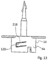
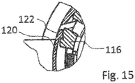
- the inner part 12 has a spiral-shaped contour 102, which starts from the peripheral wall 16 of the inner part 12 and thus projects beyond its circumferential outer surface 116.
- the spiral-shaped contour 102 which may have a strip-shaped course, thus forms a screw thread or a portion of such, as can be seen in particular from Fig. 11 results.
- This contour 102 is interrupted in the region of the slots which delimit the sections 18 and the lever elements 34, 36. This is done by the Fig. 11 equally clear. Instead of a screw can also be provided several screw threads.
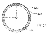
- the contour 102 extending coaxially with the longitudinal axis 118 of the vial mount has a sawtooth structure for latching engagement with a tongue-like element 120 which is cut free in the circumferential wall 44 of the outer part 14 and has one or more projections 122 extending in the direction of the contour 102, the one or more with the sawtooth profiling of the contour 102 such cooperate, that in the embodiment, the outer part 14 can be rotated exclusively in a clockwise direction, whereby the cannula 48 is adjusted in the direction of the sealing plug 26 in order to pierce the membrane 28 can.
- a counterclockwise rotation is not possible since in this case the hook-shaped projection 122 engages with correspondingly geometrically aligned projections of the sawtooth-shaped profiling of the contour 102.
- the screw thread or a portion of such a following contour 102 extends within a matching recess 124 in the peripheral wall 44 of the outer member 14, which thus forms a guide during the rotational movement.
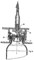
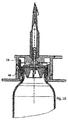
- FIG. 8 A comparison between the Fig. 8 to 10 illustrates that depending on the rotational position of the outer part 14 to the inner part 12, the cannula 48 is adjusted in the direction of the sealing plug 24.
- the position is shown in which the outer portions 38 of the lever members 34, 36 are pivoted inwardly, so that a rotation of the outer member 14 to the inner part 12 is possible.
- the starting position is shown in which a rotation of the outer part 14 to the inner part 12 can take place in order to adjust the cannula 48 in the direction of the diaphragm 28 axially.
- the outer part 14 has been adjusted relative to the inner part 12, so that already the membrane 28 is pierced by the tip 54 of the cannula 48.
- Fig. 10 reflects the end position at which the cannula 44 in desired extent the membrane 28 has penetrated. At the same time a locking of the outer part 14 with the first part 12 is possible in this position.
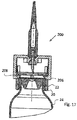
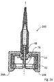
- FIG. 2 shows a further embodiment to be emphasized of a transfer device 200 which obeys the teaching according to the invention. Therefore, according to the Fig. 1 to 15 basically the same reference numerals are used for the same elements.
- the transfer device hereinafter referred to as connector 200 thus consists of the inner or first part 12 and the outer or second part 14, which are axially displaceable to each other.
- the second or outer part 14 has a plurality of preferably uniformly circumferentially distributed tongue-shaped resilient elements limited by slots 202 , 204, hereinafter referred to as tongues.
- the tongues 202, 204 have in their ends inwardly, ie in the direction of the central axis 80 of the connector 200 extending latching projections 206, 208, which may have a wedge or ramp-shaped geometry.
- latching projections 206, 208 which may have a wedge or ramp-shaped geometry.
- the locking projections 206, 208 protrude into corresponding recesses 210, 212 in the peripheral wall of the inner part 12.
- the latching projections 206, 208 remain in the recesses 210, 212 of the inner part 12 until the inwardly directed projections 20 of the first part 12 behind the lower edge of the flange-like edge 22 of the vial 24.
- the flange-like edge 22 another element enabling a fixing of the connector 200 is covered.
- Fig. 17 is shown a position in which the first part 12 with the free edge of the inwardly projecting projections 20, the bottom of the edge 22 of the vial 24 or a Vial 24 surrounding closure covers.
- the locking projections 206, 208 are bent with the spring-like tongue elements 202, 204 by cooperation with the top or the upper corner of the edge 22 to the outside, like the Fig. 18 clarified.
- the distance between the recesses 210, 212 to the latching projections 20 of the first part 12 engaging behind the underside of the edge 22 of the vial is selected such that, when the first part 12 is properly fixed to the vial 24, the latching projections 206, 208 of the second part 14 along the peripheral upper edge of the flange-like edge 22 can slide when acting on the second part 14, a force in the direction of the first part 12.
- the connector 200 fulfills the requirement that in the unused state or in the case of incorrectly surrounding the vial 24, the cannula 48 with its tip 76 is not freely accessible, ie a risk of injury is ruled out. Only when the first part 12 properly surrounds the closure region of the vial 24, a unlocking and thus activating the connector 200 is such that an axial adjustment between the first and second part 12, 14 is made possible and thus the cannula 48 can be adjusted in the direction of the membrane 28 of the sealing plug 26 for penetrating this, as can be understood from the Fig. 16 to 20 it can be seen that are self-explanatory in this respect.
Landscapes
- Health & Medical Sciences (AREA)
- Pharmacology & Pharmacy (AREA)
- Life Sciences & Earth Sciences (AREA)
- Animal Behavior & Ethology (AREA)
- General Health & Medical Sciences (AREA)
- Public Health (AREA)
- Veterinary Medicine (AREA)
- Physics & Mathematics (AREA)
- Fluid Mechanics (AREA)
- Medical Preparation Storing Or Oral Administration Devices (AREA)
Priority Applications (1)
| Application Number | Priority Date | Filing Date | Title |
|---|---|---|---|
| PL13780317T PL2903583T3 (pl) | 2012-10-01 | 2013-09-30 | Urządzenie do pobierania albo przekazywania płynu z fiolki wyposażonej w zamknięcie |
Applications Claiming Priority (3)
| Application Number | Priority Date | Filing Date | Title |
|---|---|---|---|
| DE102012109322 | 2012-10-01 | ||
| DE201210113002 DE102012113002B4 (de) | 2012-10-01 | 2012-12-21 | Transfervorrichtung zur Entnahme oder Übergabe eines Fluids |
| PCT/EP2013/070320 WO2014053430A1 (de) | 2012-10-01 | 2013-09-30 | Transfervorrichtung zur entnahme oder übergabe eines fluids |
Publications (2)
| Publication Number | Publication Date |
|---|---|
| EP2903583A1 EP2903583A1 (de) | 2015-08-12 |
| EP2903583B1 true EP2903583B1 (de) | 2016-11-09 |
Family
ID=50276184
Family Applications (1)
| Application Number | Title | Priority Date | Filing Date |
|---|---|---|---|
| EP13780317.7A Active EP2903583B1 (de) | 2012-10-01 | 2013-09-30 | Transfervorrichtung zur entnahme oder übergabe eines fluids |
Country Status (8)
| Country | Link |
|---|---|
| US (1) | US10058482B2 (pl) |
| EP (1) | EP2903583B1 (pl) |
| DE (1) | DE102012113002B4 (pl) |
| DK (1) | DK2903583T3 (pl) |
| ES (1) | ES2615479T3 (pl) |
| PL (1) | PL2903583T3 (pl) |
| PT (1) | PT2903583T (pl) |
| WO (1) | WO2014053430A1 (pl) |
Families Citing this family (19)
| Publication number | Priority date | Publication date | Assignee | Title |
|---|---|---|---|---|
| US7547300B2 (en) | 2006-04-12 | 2009-06-16 | Icu Medical, Inc. | Vial adaptor for regulating pressure |
| WO2013025946A1 (en) | 2011-08-18 | 2013-02-21 | Icu Medical, Inc. | Pressure-regulating vial adaptors |
| WO2013142618A1 (en) | 2012-03-22 | 2013-09-26 | Icu Medical, Inc. | Pressure-regulating vial adaptors |
| DE102012113002B4 (de) | 2012-10-01 | 2014-04-30 | Medac Gesellschaft für klinische Spezialpräparate mbH | Transfervorrichtung zur Entnahme oder Übergabe eines Fluids |
| US9089475B2 (en) | 2013-01-23 | 2015-07-28 | Icu Medical, Inc. | Pressure-regulating vial adaptors |
| AU2014290124B2 (en) | 2013-07-19 | 2019-05-09 | Icu Medical, Inc. | Pressure-regulating fluid transfer systems and methods |
| DE102014104281B3 (de) * | 2014-03-27 | 2015-09-10 | Medac Gesellschaft für klinische Spezialpräparate mbH | Transfervorrichtung |
| CA2953229C (en) | 2014-06-20 | 2024-01-02 | Icu Medical, Inc. | Pressure-regulating vial adaptors |
| DE102015201275A1 (de) * | 2015-01-26 | 2016-07-28 | Bayer Pharma AG | Vorrichtung zum Überführen einer Flüssigkeit zwischen einem Lagerbehälter und mindestens einem weiteren Gebrauchsbehälter |
| CA3012733C (en) | 2016-01-29 | 2023-09-12 | Icu Medical, Inc. | Pressure-regulating vial adaptors |
| DE102016110569B3 (de) * | 2016-06-08 | 2017-10-26 | Sfm Medical Devices Gmbh | Adapter |
| JP7063891B2 (ja) * | 2016-09-30 | 2022-05-09 | アイシーユー・メディカル・インコーポレーテッド | バイアルアダプタ |
| CN109862863A (zh) * | 2016-11-21 | 2019-06-07 | 泰尔茂株式会社 | 药液填充单元、药液填充组件以及填充接合器 |
| IL249408A0 (en) | 2016-12-06 | 2017-03-30 | Medimop Medical Projects Ltd | Liquid transfer device for use with infusion liquid container and pincers-like hand tool for use therewith for releasing intact drug vial therefrom |
| IL251458A0 (en) * | 2017-03-29 | 2017-06-29 | Medimop Medical Projects Ltd | Liquid drug delivery devices are user-operated for use in pre-prepared liquid drug delivery assemblies (rtu) |
| WO2019063737A1 (en) * | 2017-09-27 | 2019-04-04 | Philip Morris Products S.A. | SUPPORT ELEMENT FOR AEROSOL GENERATING ARTICLE |
| IL254802A0 (en) | 2017-09-29 | 2017-12-31 | Medimop Medical Projects Ltd | A device with two vial adapters includes two identical perforated vial adapters |
| JP1630477S (pl) | 2018-07-06 | 2019-05-07 | ||
| US11850320B2 (en) | 2018-12-20 | 2023-12-26 | Asp Global Manufacturing Gmbh | Liquid-chemical sterilization system with biological indicator |
Family Cites Families (11)
| Publication number | Priority date | Publication date | Assignee | Title |
|---|---|---|---|---|
| IT1173370B (it) * | 1984-02-24 | 1987-06-24 | Erba Farmitalia | Dispositivo di sicurezza per collegare una siringa alla imboccatura di un flacone contenente un farmaco o di un tubicino per l'erogazione del farmaco della siringa |
| IT1231892B (it) * | 1987-10-14 | 1992-01-15 | Farmitalia Carlo Erba S P A Mi | Apparecchio con organi di bloccaggio di sicurezza per il collegamento di una siringa ad un flacone contenente un farmaco |
| GB9701413D0 (en) | 1997-01-24 | 1997-03-12 | Smithkline Beecham Biolog | Novel device |
| FR2789369B1 (fr) * | 1999-02-10 | 2001-04-27 | Biodome | Dispositif de connexion entre un recipient et un contenant et ensemble pret a l'emploi comprenant un tel dispositif |
| JP4341239B2 (ja) * | 2002-12-19 | 2009-10-07 | ニプロ株式会社 | 液体移注具 |
| FR2867396B1 (fr) * | 2004-03-10 | 2006-12-22 | P2A | Performeur perforant a connexion sterile |
| DE102005006771A1 (de) * | 2005-02-15 | 2006-08-17 | Disetronic Licensing Ag | Fluidtransfervorrichtung |
| US8801689B2 (en) | 2007-08-01 | 2014-08-12 | Hospira, Inc. | Medicament admixing system |
| WO2011140596A1 (en) * | 2010-05-11 | 2011-11-17 | Noble House Group Pty. Ltd. | Medical sampling port |
| DE102012113002B4 (de) | 2012-10-01 | 2014-04-30 | Medac Gesellschaft für klinische Spezialpräparate mbH | Transfervorrichtung zur Entnahme oder Übergabe eines Fluids |
| US9033949B2 (en) * | 2012-11-27 | 2015-05-19 | Bang & Olufsen Medicom A/S | Needle protection device |
-
2012
- 2012-12-21 DE DE201210113002 patent/DE102012113002B4/de active Active
-
2013
- 2013-09-30 US US14/432,809 patent/US10058482B2/en active Active
- 2013-09-30 WO PCT/EP2013/070320 patent/WO2014053430A1/de not_active Ceased
- 2013-09-30 DK DK13780317.7T patent/DK2903583T3/en active
- 2013-09-30 PT PT137803177T patent/PT2903583T/pt unknown
- 2013-09-30 PL PL13780317T patent/PL2903583T3/pl unknown
- 2013-09-30 EP EP13780317.7A patent/EP2903583B1/de active Active
- 2013-09-30 ES ES13780317.7T patent/ES2615479T3/es active Active
Also Published As
| Publication number | Publication date |
|---|---|
| US10058482B2 (en) | 2018-08-28 |
| DK2903583T3 (en) | 2017-02-13 |
| EP2903583A1 (de) | 2015-08-12 |
| ES2615479T3 (es) | 2017-06-07 |
| DE102012113002A1 (de) | 2014-04-03 |
| PL2903583T3 (pl) | 2017-04-28 |
| US20150209232A1 (en) | 2015-07-30 |
| DE102012113002B4 (de) | 2014-04-30 |
| WO2014053430A1 (de) | 2014-04-10 |
| PT2903583T (pt) | 2017-02-13 |
Similar Documents
| Publication | Publication Date | Title |
|---|---|---|
| EP2903583B1 (de) | Transfervorrichtung zur entnahme oder übergabe eines fluids | |
| EP2667838B1 (de) | Verbindungsvorrichtung zum verbinden eines ersten reservoirs mit einem zweiten reservoir | |
| EP3122310B1 (de) | Transfervorrichtung für medien mit unlösbar verrastbarem adapter | |
| EP2531164B1 (de) | Vorrichtung zum entnehmen eines fluids aus einem behälter | |
| DE60019446T2 (de) | Flüssigkeitstransferset für phiolen und andere medizinische behälter | |
| DE69903266T2 (de) | Flüssigkeitstransfervorrichtung für phiole und verfahren | |
| DE69006483T2 (de) | Vorgeschlitzte injektionsstelle. | |
| DE102009004828B4 (de) | Injektor mit verdrängbarem Stopfenteil | |
| DE69808205T2 (de) | Vorrichtung zum Befüllen und zum Verabreichen von Spritzen | |
| AT514328B1 (de) | Transfervorrichtung | |
| EP3250171B1 (de) | Vorrichtung zum überführen einer flüssigkeit zwischen einem lagerbehälter und mindestens einem weiteren gebrauchsbehälter | |
| DE3927708A1 (de) | Kindersichere kappen- und roehrcheneinheit | |
| CH433605A (de) | Einrichtung zum Mischen von zwei Stoffen und zum Füllen einer Spritze mit der Mischung | |
| WO2009143641A1 (de) | Ampulle mit ampullenhalterung | |
| WO2006042579A1 (de) | Verschlusskappe für mit medizinischen flüssigkeiten befüllte behältnisse | |
| CH702815A1 (de) | Befüllvorrichtung zum Befüllen mindestens eines ersten Reservoirs eines Applikators. | |
| WO2023061829A1 (de) | Quetschflaschenspender mit betätigungssicherung | |
| DE69715747T2 (de) | Vorrichtung zum Befüllen und zum Verabreichen des Inhalts von Spritzen | |
| DE102004044288A1 (de) | Vorrichtung zur Verbindung eines rohrförmigen Teils, insbesondere einer Kanüle, mit dem Inneren einer Flasche oder dergleichen | |
| WO2009089638A1 (de) | Nadeleinheit mit einer zwischen nadelträger und nadelverpackungshülse angeordneten hülse | |
| DE60224940T2 (de) | Sicherheitsverpackung für eine flasche für medizinische anwendungen | |
| EP2702943A1 (de) | Vorrichtung zur Entnahme von Körperflüssigkeiten und Verfahren zum Montieren einer solchen Vorrichtung | |
| DE102013007063A1 (de) | Behältnis | |
| EP0343534B1 (de) | Flüssigkeitsaufbewahrungsbehälter insbesondere für Körperflüssigkeiten | |
| WO2016120161A1 (de) | Vorrichtung zum überführen einer flüssigkeit zwischen einem lagerbehälter und mindestens einem weiteren gebrauchsbehälter |
Legal Events
| Date | Code | Title | Description |
|---|---|---|---|
| PUAI | Public reference made under article 153(3) epc to a published international application that has entered the european phase |
Free format text: ORIGINAL CODE: 0009012 |
|
| 17P | Request for examination filed |
Effective date: 20150327 |
|
| AK | Designated contracting states |
Kind code of ref document: A1 Designated state(s): AL AT BE BG CH CY CZ DE DK EE ES FI FR GB GR HR HU IE IS IT LI LT LU LV MC MK MT NL NO PL PT RO RS SE SI SK SM TR |
|
| AX | Request for extension of the european patent |
Extension state: BA ME |
|
| DAX | Request for extension of the european patent (deleted) | ||
| GRAP | Despatch of communication of intention to grant a patent |
Free format text: ORIGINAL CODE: EPIDOSNIGR1 |
|
| INTG | Intention to grant announced |
Effective date: 20160406 |
|
| GRAS | Grant fee paid |
Free format text: ORIGINAL CODE: EPIDOSNIGR3 |
|
| GRAA | (expected) grant |
Free format text: ORIGINAL CODE: 0009210 |
|
| AK | Designated contracting states |
Kind code of ref document: B1 Designated state(s): AL AT BE BG CH CY CZ DE DK EE ES FI FR GB GR HR HU IE IS IT LI LT LU LV MC MK MT NL NO PL PT RO RS SE SI SK SM TR |
|
| REG | Reference to a national code |
Ref country code: GB Ref legal event code: FG4D Free format text: NOT ENGLISH |
|
| REG | Reference to a national code |
Ref country code: AT Ref legal event code: REF Ref document number: 843210 Country of ref document: AT Kind code of ref document: T Effective date: 20161115 Ref country code: CH Ref legal event code: EP |
|
| REG | Reference to a national code |
Ref country code: IE Ref legal event code: FG4D Free format text: LANGUAGE OF EP DOCUMENT: GERMAN |
|
| REG | Reference to a national code |
Ref country code: DE Ref legal event code: R096 Ref document number: 502013005339 Country of ref document: DE |
|
| REG | Reference to a national code |
Ref country code: NL Ref legal event code: FP |
|
| REG | Reference to a national code |
Ref country code: DK Ref legal event code: T3 Effective date: 20170209 Ref country code: PT Ref legal event code: SC4A Ref document number: 2903583 Country of ref document: PT Date of ref document: 20170213 Kind code of ref document: T Free format text: AVAILABILITY OF NATIONAL TRANSLATION Effective date: 20170206 |
|
| PG25 | Lapsed in a contracting state [announced via postgrant information from national office to epo] |
Ref country code: LV Free format text: LAPSE BECAUSE OF FAILURE TO SUBMIT A TRANSLATION OF THE DESCRIPTION OR TO PAY THE FEE WITHIN THE PRESCRIBED TIME-LIMIT Effective date: 20161109 |
|
| REG | Reference to a national code |
Ref country code: SE Ref legal event code: TRGR |
|
| REG | Reference to a national code |
Ref country code: LT Ref legal event code: MG4D |
|
| PG25 | Lapsed in a contracting state [announced via postgrant information from national office to epo] |
Ref country code: LT Free format text: LAPSE BECAUSE OF FAILURE TO SUBMIT A TRANSLATION OF THE DESCRIPTION OR TO PAY THE FEE WITHIN THE PRESCRIBED TIME-LIMIT Effective date: 20161109 Ref country code: NO Free format text: LAPSE BECAUSE OF FAILURE TO SUBMIT A TRANSLATION OF THE DESCRIPTION OR TO PAY THE FEE WITHIN THE PRESCRIBED TIME-LIMIT Effective date: 20170209 Ref country code: GR Free format text: LAPSE BECAUSE OF FAILURE TO SUBMIT A TRANSLATION OF THE DESCRIPTION OR TO PAY THE FEE WITHIN THE PRESCRIBED TIME-LIMIT Effective date: 20170210 |
|
| PG25 | Lapsed in a contracting state [announced via postgrant information from national office to epo] |
Ref country code: IS Free format text: LAPSE BECAUSE OF FAILURE TO SUBMIT A TRANSLATION OF THE DESCRIPTION OR TO PAY THE FEE WITHIN THE PRESCRIBED TIME-LIMIT Effective date: 20170309 Ref country code: RS Free format text: LAPSE BECAUSE OF FAILURE TO SUBMIT A TRANSLATION OF THE DESCRIPTION OR TO PAY THE FEE WITHIN THE PRESCRIBED TIME-LIMIT Effective date: 20161109 Ref country code: HR Free format text: LAPSE BECAUSE OF FAILURE TO SUBMIT A TRANSLATION OF THE DESCRIPTION OR TO PAY THE FEE WITHIN THE PRESCRIBED TIME-LIMIT Effective date: 20161109 |
|
| REG | Reference to a national code |
Ref country code: ES Ref legal event code: FG2A Ref document number: 2615479 Country of ref document: ES Kind code of ref document: T3 Effective date: 20170607 |
|
| PG25 | Lapsed in a contracting state [announced via postgrant information from national office to epo] |
Ref country code: EE Free format text: LAPSE BECAUSE OF FAILURE TO SUBMIT A TRANSLATION OF THE DESCRIPTION OR TO PAY THE FEE WITHIN THE PRESCRIBED TIME-LIMIT Effective date: 20161109 Ref country code: RO Free format text: LAPSE BECAUSE OF FAILURE TO SUBMIT A TRANSLATION OF THE DESCRIPTION OR TO PAY THE FEE WITHIN THE PRESCRIBED TIME-LIMIT Effective date: 20161109 |
|
| REG | Reference to a national code |
Ref country code: SK Ref legal event code: T3 Ref document number: E 23530 Country of ref document: SK |
|
| REG | Reference to a national code |
Ref country code: DE Ref legal event code: R097 Ref document number: 502013005339 Country of ref document: DE |
|
| PG25 | Lapsed in a contracting state [announced via postgrant information from national office to epo] |
Ref country code: SM Free format text: LAPSE BECAUSE OF FAILURE TO SUBMIT A TRANSLATION OF THE DESCRIPTION OR TO PAY THE FEE WITHIN THE PRESCRIBED TIME-LIMIT Effective date: 20161109 Ref country code: BG Free format text: LAPSE BECAUSE OF FAILURE TO SUBMIT A TRANSLATION OF THE DESCRIPTION OR TO PAY THE FEE WITHIN THE PRESCRIBED TIME-LIMIT Effective date: 20170209 |
|
| PLBE | No opposition filed within time limit |
Free format text: ORIGINAL CODE: 0009261 |
|
| STAA | Information on the status of an ep patent application or granted ep patent |
Free format text: STATUS: NO OPPOSITION FILED WITHIN TIME LIMIT |
|
| REG | Reference to a national code |
Ref country code: FR Ref legal event code: PLFP Year of fee payment: 5 |
|
| 26N | No opposition filed |
Effective date: 20170810 |
|
| PG25 | Lapsed in a contracting state [announced via postgrant information from national office to epo] |
Ref country code: SI Free format text: LAPSE BECAUSE OF FAILURE TO SUBMIT A TRANSLATION OF THE DESCRIPTION OR TO PAY THE FEE WITHIN THE PRESCRIBED TIME-LIMIT Effective date: 20161109 |
|
| REG | Reference to a national code |
Ref country code: CH Ref legal event code: PL |
|
| PG25 | Lapsed in a contracting state [announced via postgrant information from national office to epo] |
Ref country code: MC Free format text: LAPSE BECAUSE OF FAILURE TO SUBMIT A TRANSLATION OF THE DESCRIPTION OR TO PAY THE FEE WITHIN THE PRESCRIBED TIME-LIMIT Effective date: 20161109 |
|
| REG | Reference to a national code |
Ref country code: IE Ref legal event code: MM4A |
|
| REG | Reference to a national code |
Ref country code: BE Ref legal event code: MM Effective date: 20170930 |
|
| PG25 | Lapsed in a contracting state [announced via postgrant information from national office to epo] |
Ref country code: LU Free format text: LAPSE BECAUSE OF NON-PAYMENT OF DUE FEES Effective date: 20170930 |
|
| PG25 | Lapsed in a contracting state [announced via postgrant information from national office to epo] |
Ref country code: LI Free format text: LAPSE BECAUSE OF NON-PAYMENT OF DUE FEES Effective date: 20170930 Ref country code: IE Free format text: LAPSE BECAUSE OF NON-PAYMENT OF DUE FEES Effective date: 20170930 Ref country code: CH Free format text: LAPSE BECAUSE OF NON-PAYMENT OF DUE FEES Effective date: 20170930 |
|
| PG25 | Lapsed in a contracting state [announced via postgrant information from national office to epo] |
Ref country code: BE Free format text: LAPSE BECAUSE OF NON-PAYMENT OF DUE FEES Effective date: 20170930 |
|
| REG | Reference to a national code |
Ref country code: FR Ref legal event code: PLFP Year of fee payment: 6 |
|
| PG25 | Lapsed in a contracting state [announced via postgrant information from national office to epo] |
Ref country code: MT Free format text: LAPSE BECAUSE OF FAILURE TO SUBMIT A TRANSLATION OF THE DESCRIPTION OR TO PAY THE FEE WITHIN THE PRESCRIBED TIME-LIMIT Effective date: 20161109 |
|
| PG25 | Lapsed in a contracting state [announced via postgrant information from national office to epo] |
Ref country code: HU Free format text: LAPSE BECAUSE OF FAILURE TO SUBMIT A TRANSLATION OF THE DESCRIPTION OR TO PAY THE FEE WITHIN THE PRESCRIBED TIME-LIMIT; INVALID AB INITIO Effective date: 20130930 |
|
| PG25 | Lapsed in a contracting state [announced via postgrant information from national office to epo] |
Ref country code: CY Free format text: LAPSE BECAUSE OF FAILURE TO SUBMIT A TRANSLATION OF THE DESCRIPTION OR TO PAY THE FEE WITHIN THE PRESCRIBED TIME-LIMIT Effective date: 20161109 |
|
| REG | Reference to a national code |
Ref country code: AT Ref legal event code: MM01 Ref document number: 843210 Country of ref document: AT Kind code of ref document: T Effective date: 20180930 |
|
| PG25 | Lapsed in a contracting state [announced via postgrant information from national office to epo] |
Ref country code: MK Free format text: LAPSE BECAUSE OF FAILURE TO SUBMIT A TRANSLATION OF THE DESCRIPTION OR TO PAY THE FEE WITHIN THE PRESCRIBED TIME-LIMIT Effective date: 20161109 |
|
| PG25 | Lapsed in a contracting state [announced via postgrant information from national office to epo] |
Ref country code: AT Free format text: LAPSE BECAUSE OF NON-PAYMENT OF DUE FEES Effective date: 20180930 |
|
| PG25 | Lapsed in a contracting state [announced via postgrant information from national office to epo] |
Ref country code: TR Free format text: LAPSE BECAUSE OF FAILURE TO SUBMIT A TRANSLATION OF THE DESCRIPTION OR TO PAY THE FEE WITHIN THE PRESCRIBED TIME-LIMIT Effective date: 20161109 |
|
| PG25 | Lapsed in a contracting state [announced via postgrant information from national office to epo] |
Ref country code: AL Free format text: LAPSE BECAUSE OF FAILURE TO SUBMIT A TRANSLATION OF THE DESCRIPTION OR TO PAY THE FEE WITHIN THE PRESCRIBED TIME-LIMIT Effective date: 20161109 |
|
| P01 | Opt-out of the competence of the unified patent court (upc) registered |
Effective date: 20230525 |
|
| PGFP | Annual fee paid to national office [announced via postgrant information from national office to epo] |
Ref country code: FI Payment date: 20240918 Year of fee payment: 12 |
|
| PGFP | Annual fee paid to national office [announced via postgrant information from national office to epo] |
Ref country code: DK Payment date: 20240923 Year of fee payment: 12 |
|
| PGFP | Annual fee paid to national office [announced via postgrant information from national office to epo] |
Ref country code: PT Payment date: 20240919 Year of fee payment: 12 |
|
| PGFP | Annual fee paid to national office [announced via postgrant information from national office to epo] |
Ref country code: NL Payment date: 20240918 Year of fee payment: 12 |
|
| PGFP | Annual fee paid to national office [announced via postgrant information from national office to epo] |
Ref country code: CZ Payment date: 20240923 Year of fee payment: 12 |
|
| PGFP | Annual fee paid to national office [announced via postgrant information from national office to epo] |
Ref country code: PL Payment date: 20240826 Year of fee payment: 12 |
|
| PGFP | Annual fee paid to national office [announced via postgrant information from national office to epo] |
Ref country code: SK Payment date: 20240924 Year of fee payment: 12 |
|
| PGFP | Annual fee paid to national office [announced via postgrant information from national office to epo] |
Ref country code: SE Payment date: 20240919 Year of fee payment: 12 |
|
| PGFP | Annual fee paid to national office [announced via postgrant information from national office to epo] |
Ref country code: IT Payment date: 20250923 Year of fee payment: 13 |
|
| PGFP | Annual fee paid to national office [announced via postgrant information from national office to epo] |
Ref country code: GB Payment date: 20250822 Year of fee payment: 13 |
|
| PGFP | Annual fee paid to national office [announced via postgrant information from national office to epo] |
Ref country code: FR Payment date: 20250922 Year of fee payment: 13 |
|
| PGFP | Annual fee paid to national office [announced via postgrant information from national office to epo] |
Ref country code: DE Payment date: 20250929 Year of fee payment: 13 |
|
| PGFP | Annual fee paid to national office [announced via postgrant information from national office to epo] |
Ref country code: ES Payment date: 20251028 Year of fee payment: 13 |
|
| PG25 | Lapsed in a contracting state [announced via postgrant information from national office to epo] |
Ref country code: FI Free format text: LAPSE BECAUSE OF NON-PAYMENT OF DUE FEES Effective date: 20250930 |
|
| REG | Reference to a national code |
Ref country code: DK Ref legal event code: EBP Effective date: 20250930 |
|
| PG25 | Lapsed in a contracting state [announced via postgrant information from national office to epo] |
Ref country code: PT Free format text: LAPSE BECAUSE OF NON-PAYMENT OF DUE FEES Effective date: 20260331 Ref country code: CZ Free format text: LAPSE BECAUSE OF NON-PAYMENT OF DUE FEES Effective date: 20250930 |