EP2902729B1 - Chauffage de type pompe à chaleur et appareil d'alimentation en eau chaude - Google Patents
Chauffage de type pompe à chaleur et appareil d'alimentation en eau chaude Download PDFInfo
- Publication number
- EP2902729B1 EP2902729B1 EP15152741.3A EP15152741A EP2902729B1 EP 2902729 B1 EP2902729 B1 EP 2902729B1 EP 15152741 A EP15152741 A EP 15152741A EP 2902729 B1 EP2902729 B1 EP 2902729B1
- Authority
- EP
- European Patent Office
- Prior art keywords
- temperature
- compressor
- speed
- going
- control means
- Prior art date
- Legal status (The legal status is an assumption and is not a legal conclusion. Google has not performed a legal analysis and makes no representation as to the accuracy of the status listed.)
- Not-in-force
Links
- XLYOFNOQVPJJNP-UHFFFAOYSA-N water Substances O XLYOFNOQVPJJNP-UHFFFAOYSA-N 0.000 title claims description 316
- 238000010438 heat treatment Methods 0.000 title claims description 175
- 239000003507 refrigerant Substances 0.000 claims description 106
- 230000007423 decrease Effects 0.000 claims description 42
- 230000003247 decreasing effect Effects 0.000 claims description 20
- 238000001514 detection method Methods 0.000 claims description 5
- 238000013459 approach Methods 0.000 claims 1
- 238000000034 method Methods 0.000 description 26
- 230000008569 process Effects 0.000 description 26
- 230000015556 catabolic process Effects 0.000 description 11
- 238000006731 degradation reaction Methods 0.000 description 11
- 238000007906 compression Methods 0.000 description 8
- 230000005494 condensation Effects 0.000 description 8
- 238000009833 condensation Methods 0.000 description 8
- 238000005259 measurement Methods 0.000 description 7
- 239000000284 extract Substances 0.000 description 5
- 230000017525 heat dissipation Effects 0.000 description 5
- 230000008859 change Effects 0.000 description 4
- 238000005516 engineering process Methods 0.000 description 4
- 238000001704 evaporation Methods 0.000 description 4
- 230000008020 evaporation Effects 0.000 description 4
- 238000001816 cooling Methods 0.000 description 3
- 230000006872 improvement Effects 0.000 description 3
- 238000007599 discharging Methods 0.000 description 2
- 230000005855 radiation Effects 0.000 description 2
- 230000006835 compression Effects 0.000 description 1
- 230000006837 decompression Effects 0.000 description 1
- 238000010586 diagram Methods 0.000 description 1
- 238000012986 modification Methods 0.000 description 1
- 230000004048 modification Effects 0.000 description 1
- 239000008399 tap water Substances 0.000 description 1
- 235000020679 tap water Nutrition 0.000 description 1
Images


Classifications
-
- F—MECHANICAL ENGINEERING; LIGHTING; HEATING; WEAPONS; BLASTING
- F25—REFRIGERATION OR COOLING; COMBINED HEATING AND REFRIGERATION SYSTEMS; HEAT PUMP SYSTEMS; MANUFACTURE OR STORAGE OF ICE; LIQUEFACTION SOLIDIFICATION OF GASES
- F25B—REFRIGERATION MACHINES, PLANTS OR SYSTEMS; COMBINED HEATING AND REFRIGERATION SYSTEMS; HEAT PUMP SYSTEMS
- F25B49/00—Arrangement or mounting of control or safety devices
- F25B49/02—Arrangement or mounting of control or safety devices for compression type machines, plants or systems
-
- F—MECHANICAL ENGINEERING; LIGHTING; HEATING; WEAPONS; BLASTING
- F25—REFRIGERATION OR COOLING; COMBINED HEATING AND REFRIGERATION SYSTEMS; HEAT PUMP SYSTEMS; MANUFACTURE OR STORAGE OF ICE; LIQUEFACTION SOLIDIFICATION OF GASES
- F25B—REFRIGERATION MACHINES, PLANTS OR SYSTEMS; COMBINED HEATING AND REFRIGERATION SYSTEMS; HEAT PUMP SYSTEMS
- F25B13/00—Compression machines, plants or systems, with reversible cycle
-
- F—MECHANICAL ENGINEERING; LIGHTING; HEATING; WEAPONS; BLASTING
- F25—REFRIGERATION OR COOLING; COMBINED HEATING AND REFRIGERATION SYSTEMS; HEAT PUMP SYSTEMS; MANUFACTURE OR STORAGE OF ICE; LIQUEFACTION SOLIDIFICATION OF GASES
- F25B—REFRIGERATION MACHINES, PLANTS OR SYSTEMS; COMBINED HEATING AND REFRIGERATION SYSTEMS; HEAT PUMP SYSTEMS
- F25B2339/00—Details of evaporators; Details of condensers
- F25B2339/04—Details of condensers
- F25B2339/047—Water-cooled condensers
-
- F—MECHANICAL ENGINEERING; LIGHTING; HEATING; WEAPONS; BLASTING
- F25—REFRIGERATION OR COOLING; COMBINED HEATING AND REFRIGERATION SYSTEMS; HEAT PUMP SYSTEMS; MANUFACTURE OR STORAGE OF ICE; LIQUEFACTION SOLIDIFICATION OF GASES
- F25B—REFRIGERATION MACHINES, PLANTS OR SYSTEMS; COMBINED HEATING AND REFRIGERATION SYSTEMS; HEAT PUMP SYSTEMS
- F25B2600/00—Control issues
- F25B2600/02—Compressor control
- F25B2600/025—Compressor control by controlling speed
-
- F—MECHANICAL ENGINEERING; LIGHTING; HEATING; WEAPONS; BLASTING
- F25—REFRIGERATION OR COOLING; COMBINED HEATING AND REFRIGERATION SYSTEMS; HEAT PUMP SYSTEMS; MANUFACTURE OR STORAGE OF ICE; LIQUEFACTION SOLIDIFICATION OF GASES
- F25B—REFRIGERATION MACHINES, PLANTS OR SYSTEMS; COMBINED HEATING AND REFRIGERATION SYSTEMS; HEAT PUMP SYSTEMS
- F25B2700/00—Sensing or detecting of parameters; Sensors therefor
- F25B2700/21—Temperatures
- F25B2700/2116—Temperatures of a condenser
- F25B2700/21161—Temperatures of a condenser of the fluid heated by the condenser
Definitions
- the present invention relates to a heat pump-type heating and hot-water supply apparatus that exchanges heat between refrigerant and water.
- a heat pump-type heating and hot-water supply apparatus has conventionally been known which uses hot water generated by heat exchange between refrigerant and water for heating and hot-water supply.
- the heat pump-type heating and hot-water supply apparatus includes a heat pump unit having a refrigerant circuit and a hot-water supply unit (see, for example, JP-A-2005-274021 ).
- the refrigerant circuit includes a compressor, a water/refrigerant heat exchanger that exchanges heat between refrigerant and water, an expansion valve, a heat source side heat exchanger, and a refrigerant pipe that connects them sequentially.
- the hot-water supply unit supplies hot water heated by the water/refrigerant heat exchanger to a heating unit (such as a floor heating panel or bathroom heating apparatus) or water storage tank by a circulation pump.
- the speed of the compressor and the opening degree of the expansion valve are controlled so that the temperature of the hot water heated by the heat exchange with the refrigerant and flowing out of the water/refrigerant heat exchanger (hereinafter described as the going temperature) reaches a given target temperature.
- the target temperature is determined depending on, for example, a room temperature requested by the heating unit, or a water heating temperature to heat the water stored in the water storage tank.
- the above-mentioned room temperature requested by the heating unit, and water heating temperature may be described as the set temperature.
- a control to maintain the temperature is performed. Specifically, the speed of the compressor is controlled so that the going temperature falls within a given range of the target temperature (for example, within ⁇ 2°C of the target temperature).
- the target temperature for example, within ⁇ 2°C of the target temperature.
- the room temperature of a room where the heating unit is installed, or a water temperature in the water storage tank becomes a temperature close to its set temperature. Hence, the amount of heat dissipation of the hot water flowing out of the water/refrigerant heat exchanger and flowing into the heating unit or water storage tank in the heating unit or water storage tank is reduced.
- the operating efficiency of the compressor varies depending on the type of compressor and the outside temperature.
- the compressor is designed to have its maximum operating efficiency of the compressor when the speed of the compressor is a given speed.
- the operating efficiency of the compressor is degraded, in other words, the efficiency of the compression process out of the above-mentioned four processes in the heat pump unit, is degraded.
- the efficiency of the heat pump unit largely depends on the operating efficiency of the compressor. In other words, when the speed of the compressor is the given speed, the heat pump unit has the maximum efficiency.
- the efficiency of the heat pump unit is degraded.
- the above-mentioned going temperature is controlled so as to fall within the given range of the target temperature, in the case that the going temperature is equal to or more than an upper limit temperature within the given range, the going temperature is decreased to the target temperature by decreasing the speed of the compressor.
- the speed of the compressor is decreased as compared to a speed at which the compressor obtains the highest value of the operating efficiency, the efficiency of the heat pump unit is degraded. Accordingly, it may degrade the COP (Coefficient Of Performance) of the heat pump-type heating and hot-water supply apparatus.
- Document EP 2 312 226 A2 describes a heat pump-type heating and hot-water supply apparatus having the features specified in the preamble of claim 1.
- the control means are configured to control the compressor.
- the control means rotates the compressor so that the current temperature of the discharging hot water which is detected by the discharging hot water temperature sensor may reach an objective temperature which has been set in advance.
- One object of the present invention is to provide a heat pump-type heating and hot-water supply apparatus that suppresses the degradation of the COP when controlling the compressor to decrease the going temperature.
- a heat pump-type heating and hot-water supply apparatus comprising the features of claim 1.
- the control means judges whether or not the speed of the compressor has decreased by a given speed or more as compared to the optimum speed corresponding to the highest value of the COP (whether or not at or below the lower limit speed) when decreasing the speed of the compressor.
- the control means judges whether or not the going temperature (water temperature) is equal to or more than the upper limit temperature that is higher by a given temperature than the target temperature. If the going temperature is equal to or more than the upper limit temperature, the control means stops the compressor.
- the control means continues to operate the compressor at a speed that is lower by a given speed than the optimum speed corresponding to the highest value of the COP (the lower limit speed). Consequently, in the heat pump-type heating and hot-water supply apparatus, it is possible to maintain the going temperature at a temperature around the target temperature, and to suppress the degradation of the COP resulting from the degradation of the operating efficiency of the compressor.
- the heat pump-type heating and hot-water supply apparatus includes a water storage tank and an indoor unit, which are heating terminals of the present invention.
- a water/refrigerant heat exchanger supplies hot water obtained by heat exchange between water and refrigerant to the indoor unit.
- the water/refrigerant heat exchanger heats water stored in the water storage tank by the hot water obtained by the heat exchange between the water and the refrigerant.
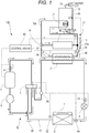
- Fig. 1 illustrates the configuration of a heat pump-type heating and hot-water supply apparatus 100 according to a first example.
- the heat pump-type heating and hot-water supply apparatus 100 includes a refrigerant circuit 10.
- the refrigerant circuit 10 includes a variable capacity compressor 1, a four-way valve 2, a water/refrigerant heat exchanger 3 that exchanges heat between refrigerant and water, an expansion valve 4, a heat source side heat exchanger 5, an accumulator 6, and a refrigerant pipe 11 that connects them sequentially.
- the four-way valve 2 of the refrigerant circuit 10 is switched and accordingly a refrigerant circulation direction can be switched.
- the refrigerant pipe 11 in the vicinity of a refrigerant discharge opening of the compressor 1 is provided with a discharge temperature sensor 51 for detecting the temperature of the refrigerant discharged from the compressor 1.
- the refrigerant pipe 11 between the water/refrigerant heat exchanger 3 and the expansion valve 4 is provided with a refrigerant temperature sensor 53.
- the refrigerant temperature sensor 53 detects the temperature of the refrigerant flowing out of the water/refrigerant heat exchanger 3 when the water/refrigerant heat exchanger 3 functions as a condenser.
- the refrigerant temperature sensor 53 detects the temperature of the refrigerant flowing into the water/refrigerant heat exchanger 3 when the water/refrigerant heat exchanger 3 functions as an evaporator.
- the refrigerant pipe 11 between the expansion valve 4 and the heat source side heat exchanger 5 is provided with a heat exchanger temperature sensor 54.
- the heat exchanger temperature sensor 54 detects the temperature of the refrigerant flowing into the heat source side heat exchanger 5 when the heat source side heat exchanger 5 functions as an evaporator.
- the heat exchanger temperature sensor 54 detects the temperature of the refrigerant flowing out of the heat source side heat exchanger 5 when the heat source side heat exchanger 5 functions as a condenser.
- the refrigerant pipe 11 on the discharge side of the compressor 1 (between the four-way valve 2 and the water/refrigerant heat exchanger 3) is provided with a pressure sensor 50.
- an outside temperature sensor (outside temperature detection means) 52 is provided in the vicinity of the heat source side heat exchanger 5.
- a fan 7 is placed in the vicinity of the heat source side heat exchanger 5.
- the fan 7 takes in outside air into an unillustrated housing of the heat pump-type heating and hot-water supply apparatus 100 and accordingly supplies the outside air to the heat source side heat exchanger 5.
- the fan 7 is attached to an unillustrated output shaft (rotating shaft) of a motor whose speed is variable.
- the expansion valve 4 is configured to be capable of pulse control over the degree of opening of the expansion valve 4 using a stepping motor.
- the water/refrigerant heat exchanger 3 is connected to the refrigerant pipe 11 and a hot-water supply pipe 12a.
- an end of the hot-water supply pipe 12a is connected to a three-way valve 31.
- Both of an end of an indoor unit side pipe 12c and an end of a water storage tank side pipe 12b are connected to the three-way valve 31.
- the other end of the hot-water supply pipe 12a is connected to the other end of the indoor unit side pipe 12c and the other end of the water storage tank side pipe 12b.
- a joint between the hot-water supply pipe 12a, the water storage tank side pipe 12b, and the indoor unit side pipe 12c is set as a connection point 13.
- the indoor unit side pipe 12c is provided with an indoor unit 40 such as a floor heating apparatus or radiator.
- the water storage tank side pipe 12b is provided with a water storage tank 70.
- a heat exchange unit 71 formed into a spiral shape is provided in a lower part of the water storage tank 70. Both ends of the heat exchange unit 71 are connected to the water storage tank side pipe 12b. Consequently, the hot water flowing through the water storage tank side pipe 12b flows into the heat exchange unit 71.
- a hot-water outlet 73 for supplying the hot water stored in the water storage tank 70 to a bathtub, a wash basin faucet, or the like is provided at the top of the water storage tank 70.
- a water inlet 72 for supplying water into the water storage tank 70 is provided at the bottom of the water storage tank 70. The water inlet 72 is directly coupled to an unillustrated water pipe.
- a variable capacity circulation pump 30 is provided between the connection point 13 and the water/refrigerant heat exchanger 3.
- the circulation pump 30 is driven to circulate the water that has exchanged heat with the refrigerant by the water/refrigerant heat exchanger 3 in a direction of an arrow 90 illustrated in Fig. 1 .
- the water flowing out of the water/refrigerant heat exchanger 3 flows into the indoor unit 40 via the indoor unit side pipe 12c or into the water storage tank 70 via the water storage tank side pipe 12b, in accordance with the switched state of the three-way valve 31.
- the water flowing out of the indoor unit 40 or the water storage tank 70 flows into the water/refrigerant heat exchanger 3 via the connection point 13.
- the water/refrigerant heat exchanger 3, the circulation pump 30, the indoor unit 40, and the water storage tank 70 are connected by the hot-water supply pipe 12a, the water storage tank side pipe 12b, and the indoor unit side pipe 12c to configure a hot-water supply circuit 12 of the heat pump-type heating and hot-water supply apparatus 100.
- a water inlet side of the water/refrigerant heat exchanger 3 of the hot-water supply pipe 12a is provided with an inlet temperature sensor 56.
- the inlet temperature sensor 56 detects a return temperature that is the temperature of the water flowing into the water/refrigerant heat exchanger 3.
- a water outlet side of the water/refrigerant heat exchanger 3 of the hot-water supply pipe 12a is provided with an outlet temperature sensor 57.
- the outlet temperature sensor 57 is going temperature detection means that detects the going temperature that is the temperature of the water flowing out of the water/refrigerant heat exchanger 3.
- a water storage tank temperature sensor 58 is provided at a substantially central portion in the vertical direction inside the water storage tank 70. The water storage tank temperature sensor 58 detects the temperature of the hot water built up inside the water storage tank 70.
- the heat pump-type heating and hot-water supply apparatus 100 includes control means 60.
- the control means 60 captures the temperature detected by each temperature sensor and the refrigerant pressure detected by the pressure sensor 50, or an operation request of a user by an unillustrated remote controller or the like, and performs various controls related to the operation of the heat pump-type heating and hot-water supply apparatus 100 depending on them.
- the control means 60 performs, for example, the drive control of the compressor 1, the fan 7, and the circulation pump 30, the switching control of the four-way valve 2, the control of the degree of opening of the expansion valve 4, and the switching control of the three-way valve 31.
- the control means 60 includes a timer unit that measures the time, and a storage unit (both are not illustrated). For example, values detected by various sensors, and a control program of the heat pump-type heating and hot-water supply apparatus 100 are stored in the storage unit.
- the refrigerant discharged from the compressor 1 flows through the four-way valve 2, the water/refrigerant heat exchanger 3, the expansion valve 4, and the heat source side heat exchanger 5 sequentially, and flows back into the four-way valve 2, and is suctioned by the compressor 1 via the accumulator 6 (an arrow 80 illustrated in Fig. 1 indicates the flow of the refrigerant).
- the heat pump-type heating and hot-water supply apparatus 100 when the heat pump-type heating and hot-water supply apparatus 100 is operated setting the refrigerant circuit 10 as a cooling cycle, the refrigerant discharged from the compressor 1 flows through the four-way valve 2, the heat source side heat exchanger 5, the expansion valve 4, and the water/refrigerant heat exchanger 3 sequentially, and flows back into the four-way valve 2, and is suctioned by the compressor 1 via the accumulator 6.
- the refrigerant flows in the opposite direction to the refrigerant flow direction (direction of the arrow 80) in the heating cycle.
- Fig. 1 the description of the refrigerant flow direction in the cooling cycle is omitted.
- the control means 60 starts the circulation pump 30 at a given speed. Furthermore, the control means 60 switches the three-way valve 31 so that hot water flows through the indoor unit side pipe 12c. Consequently, the hot water circulates between the water/refrigerant heat exchanger 3 and the indoor unit 40.
- control means 60 switches the four-way valve 2 so as to set the refrigerant circuit 10 to the heating cycle. Specifically, the control means 60 switches the four-way valve 2 so as to connect the discharge side of the compressor 1 to the water/refrigerant heat exchanger 3, and connect an intake side of the compressor 1 to the heat source side heat exchanger 5. Consequently, the water/refrigerant heat exchanger 3 functions as a condenser as well as the heat source side heat exchanger 5 functions as an evaporator.
- control means 60 starts the compressor 1 and the fan 7 to start the heating operation of the heat pump-type heating and hot-water supply apparatus 100.
- the control means 60 controls the compressor 1 so that the going temperature detected by the outlet temperature sensor 57, in other words, the temperature of the water heated by the water/refrigerant heat exchanger 3, reaches a water temperature corresponding to a set temperature of the heating operation, the set temperature having been set by the user (hereinafter described as the target temperature).
- the refrigerant discharged from the compressor 1 passes through the four-way valve 2, is condensed by heat exchange with water by the water/refrigerant heat exchanger 3, is further decompressed by the expansion valve 4, evaporates by heat exchange with the outside air by the heat source side heat exchanger 5, is suctioned into the compressor 1, and compressed again by the compressor 1.
- the processes of condensation, decompression (expansion), evaporation, and compression on the refrigerant are repeated.
- the hot water heated by the water/refrigerant heat exchanger 3 flows out to the hot-water supply pipe 12a by the drive of the circulation pump 30. Furthermore, the hot water flows into the indoor unit 40 via the three-way valve 31 and the indoor unit side pipe 12c. A room where the indoor unit 40 is installed is heated by the heat dissipation of the hot water flowing through the indoor unit 40. The hot water flowing out of the indoor unit 40 flows into the water/refrigerant heat exchanger 3 via the connection point 13 and the circulation pump 30, and is reheated by heat exchange with the refrigerant.
- the control means 60 performs the drive control of the compressor 1 so that the going temperature detected by the outlet temperature sensor 57 reaches the target temperature corresponding to the set temperature of the heating operation set by the user.
- the control means 60 controls the compressor 1 so that the going temperature detected by the outlet temperature sensor 57 reaches the target temperature corresponding to a water heating temperature (described below).
- the water heating temperature is a target value of the temperature of the water stored in the water storage tank 70.
- the control of the refrigerant circuit 10 during the water heating operation is the same as the one during the above-mentioned heating operation. Accordingly, its detailed description is omitted.
- the hot water stored in the water storage tank 70 decreases in amount by flowing out of the hot-water outlet 73.
- the water inlet 72 is directly coupled to the water pipe as described above. Hence, the pressure of the tap water causes water to be supplied by the decreased amount from the water inlet 72 to the water storage tank 70. Consequently, the temperature of the hot water stored in the water storage tank 70 decreases.
- the control means 60 always monitors a water storage tank temperature detected by the water storage tank temperature sensor 58, which is the temperature of the hot water stored in the water storage tank 70.
- the control means 60 starts the water heating operation to bring the temperature of the hot water stored in the water storage tank 70 to the water heating temperature, when the detected water storage tank temperature increases to or above a temperature that is lower by a predetermined given temperature (for example, 5°C) than the water heating temperature (hereinafter described as the water heating start temperature).
- the control means 60 starts the circulation pump 30 at a given speed and also switches the three-way valve 31 so as to flow water through the water storage tank side pipe 12b. Consequently, hot water circulates between the water/refrigerant heat exchanger 3 and the water storage tank 70.
- the hot water heated by the water/refrigerant heat exchanger 3 flows out from the water/refrigerant heat exchanger 3 to the hot-water supply pipe 12a by the operation of the circulation pump 30, flows through the water storage tank side pipe 12b via the three-way valve 31, and flows into the heat exchange unit 71 placed in the water storage tank 70.
- the water stored in the water storage tank 70 is heated by the hot water flowing through the heat exchange unit 71.
- the hot water flowing out of the heat exchange unit 71 flows into the water/refrigerant heat exchanger 3 via the connection point 13 and the circulation pump 30, and is reheated by heat exchange with the refrigerant.
- the speed of the compressor 1 is controlled so that the going temperature detected by the outlet temperature sensor 57 (hereinafter described as the going temperature Tg) reaches the target temperature (hereinafter described as the target temperature Tt).
- the COP the value of the COP of the heat pump-type heating and hot-water supply apparatus 100 changes depending on the speed of the compressor 1. The relationship between the speed of the compressor 1 and the COP is described in detail with reference to Fig. 2 .
- Fig. 2 is a drawing illustrating the relationship between the speed of the compressor 1 (hereinafter described as the compressor speed R) and the COP.
- the vertical axis indicates the value of the COP.
- the horizontal axis indicates the compressor speed R (unit: rps).
- Fig. 2 depicts as an example, the relationship between the compressor speed R and the COP at different outside temperatures To1 and To2 (To1 > To2), where the outside temperature is To.
- the speed of the compressor 1 is controlled so that the going temperature Tg falls within a given range of the target temperature Tt.
- the target temperature Tt is 40°C
- the speed of the compressor 1 is controlled so that the going temperature Tg is equal to or more than 38°C (hereinafter described as the lower limit temperature Tt2), and less than 42°C (hereinafter described as the upper limit temperature Tt1).
- the going temperature Tg reaches a temperature around the target temperature Tt, the temperature of the room where the indoor unit 40 is installed or the water temperature in the water storage tank 70 is close to each set temperature. Hence, the amount of the heat dissipation of the hot water flowing out of the water/refrigerant heat exchanger 3 and flowing into the indoor unit 40 or the water storage tank 70 decreases.
- the going temperature Tg is stabilized at a temperature around the target temperature Tt.
- the condensation temperature in the water/refrigerant heat exchanger 3 will hardly change. In other words, out of the four processes (compression process/condensation process/expansion process/evaporation process) in the refrigerant circuit 10, the three processes excluding the compression process hardly changes in efficiency.
- the operating efficiency of the compressor 1 varies depending on the type of compressor 1 and the outside temperature To.
- the compressor 1 is so designed as to have the maximum operating efficiency when the speed of the compressor 1 is an optimum speed Rm.
- the speed of the compressor 1 increases or decreases as compared to the optimum speed Rm, the operating efficiency of the compressor 1 is degraded.
- the efficiency of the compression process out of the above-mentioned four processes (compression process/condensation process/expansion process/evaporation process) in the refrigerant circuit 10 is degraded. This results from the operating efficiency property of a motor mounted in the compressor 1.
- the efficiency of the refrigerant circuit 10 of the heat pump-type heating and hot-water supply apparatus 100 depends largely on the operating efficiency of the compressor 1 in the case that the condensation temperature in the water/refrigerant heat exchanger 3 hardly changes.
- the compressor speed R is the optimum speed Rm
- the refrigerant circuit 10 has the maximum operating efficiency.
- the compressor speed R increases or decreases as compared to the optimum speed Rm, the operating efficiency of the refrigerant circuit 10 is degraded.
- the compressor speed R is decreased to decrease the going temperature Tg to the target temperature Tt.
- the efficiency of the refrigerant circuit 10 is degraded. Accordingly, the COP of the heat pump-type heating and hot-water supply apparatus 100 is degraded.
- the compressor speed R at which the COP has its highest value in other words, the optimum speed Rm at which the compressor 1 has the maximum operating efficiency, is present at each of the outside temperatures To1 and To2.
- the COP has a highest value C1.
- the compressor speed R is an optimum speed Rm2 at the outside temperature To2
- the COP has a highest value C2.
- Rm1 ⁇ Rm2 and C1 > C2.
- the lower the outside temperature To the higher the COP at a lower compressor speed R.
- the compressor speed R decreases as compared to the optimum speeds Rm1 and Rm2, respectively, at the outside temperatures To1 and To2, the COP is degraded.
- the control means 60 stops the compressor 1.
- the control means 60 decreases the compressor speed R and, when the compressor speed R reaches a lower limit speed Rd1 or Rd2 that is lower by 10% than the optimum speed Rm1 or Rm2 (see points P1 and P2 of Fig. 2 ), stops the compressor 1.
- the compressor speed table 200 illustrated in Fig. 3 is stored in the unillustrated storage unit of the control means 60.
- the compressor speed table 200 is created based on the result of an examination carried out in advance, and the like, and stored in the control means 60.
- the optimum speed Rm and the lower limit speed Rd are defined in the compressor speed table 200, in accordance with the outside temperature To and the target temperature Tt.
- the optimum speed Rm is a compressor speed corresponding to the highest value of the COP (a compressor speed at which the COP has the highest value).
- the lower limit speed Rd is lower by a given rate (in the example, 10%) than the optimum speed Rm.
- the outside temperature To is divided into three temperature ranges: less than 5°C, 5°C or more and less than 10°C, and 10°C or more.
- the target temperature Tt is divided into three temperature ranges: less than 30°C, 30°C or more and less than 40°C, and 40°C or more, and assigned to each of the three temperature ranges of the outside temperature To.
- the optimum speed Rm is defined as 30 rps, and the lower limit speed Rd as 27 rps.
- the optimum speed Rm is defined as 35 rps, and the lower limit speed Rd as 32 rps.
- the optimum speed Rm is defined as 40 rps, and the lower limit speed Rd as 36 rps.
- the optimum speed Rm and the lower limit speed Rd are defined so as to increase as the target temperature Tt increases.
- the optimum speed Rm and the lower limit speed Rd in each temperature range of the outside temperature To in the case where the target temperature Tt is 40°C or more are described above.
- the optimum speed Rm is 40 rps and the lower limit speed Rd is 36 rps, as described above.
- the optimum speed Rm is 35 rps is defined as 35 rps, and the lower limit speed Rd as 32 rps.
- the optimum speed Rm is defined as 30 rps, and the lower limit speed Rd as 27 rps.
- the optimum speed Rm and the lower limit speed Rd are defined so as to decease as the outside temperature To increases.
- FIG. 4 illustrates the flow of a process of when the compressor 1 is controlled so that the going temperature Tg falls between the upper limit temperature Tt1 and the lower limit temperature Tt2 during the heating or water heating operation of the heat pump-type heating and hot-water supply apparatus 100.
- ST represents a step and the subsequent numeral represents a step number.
- the omitted controls include, for example, the control of the compressor 1 and the control of the degree of opening of the expansion valve 4 when the going temperature Tg is increased to the target temperature Tt.
- the control means 60 captures the going temperature Tg detected by the outlet temperature sensor 57, and judges whether or not the going temperature Tg is equal to or more than the target temperature Tt (ST1).
- the target temperature Tt is set by the user and stored in the storage unit at the start of the heating or water heating operation. If the going temperature Tg is not equal to or more than the target temperature Tt (ST1 - No), the control means 60 returns the processing to ST1, and maintains the current compressor speed R.
- the control means 60 continues to drive the compressor 1 setting the compressor speed R to a starting speed (for example, 60 rps) until the going temperature Tg reaches the target temperature Tt.
- the control means 60 captures the going temperature Tg at given time intervals (for example, at intervals of 30 seconds).
- the control means 60 decreases the compressor speed R (ST2).
- the control means 60 decreases the compressor speed R in decrements of a given speed, for example, 2 rps/30 seconds.
- the control means 60 judges whether or not the compressor speed R is equal to or below the lower limit speed Rd (ST3).
- the control means 60 captures the outside temperature To detected by the outside temperature sensor 52 at given time intervals (for example, at intervals of 30 seconds).
- the control means 60 uses the outside temperature To and the stored target temperature Tt, refers to the compressor speed table 200, and extracts the lower limit speed Rd.
- the control means 60 If the compressor speed R is not equal to or below the lower limit speed Rd (ST3 - No), the control means 60 returns the processing to ST2, and continues to decrease the compressor speed R. If the compressor speed R is equal to or below the lower limit speed Rd (ST3 - Yes), the control means 60 sets the compressor speed R to the lower limit speed Rd, and judges whether or not the going temperature Tg is less than the upper limit temperature Tt1 (ST4).
- the control means 60 continues to operate the compressor 1 at the lower limit speed Rd (ST11), and returns the processing to ST4. If the going temperature Tg is not less than the upper limit temperature Tt1 (ST4 - No), the control means 60 stops the compressor 1 (ST5).
- the control means 60 judges whether or not the going temperature Tg is equal to or less than the lower limit temperature Tt2 (ST6). If the going temperature Tg is not equal to or less than the lower limit temperature Tt2 (ST6 - No), the control means 60 returns the processing to ST5, and continues to stop the compressor 1. If the going temperature Tg is equal to or less than the lower limit temperature Tt2 (ST6 - Yes), the control means 60 restarts the compressor 1 at the lower limit speed Rd (ST7).
- the control means 60 After restarting the compressor 1, the control means 60 causes the timer to start measuring the time (ST8), and judges whether or not a given time has passed since the start of the time measurement (ST9).
- the given time here is, for example, 10 minutes.
- the given time is such a time as that the operating efficiency of the compressor 1 is degraded unless the compressor 1 continues to be driven over the given time or more.
- control means 60 If the given time has not passed (ST9 - No), the control means 60 returns the processing to ST9, and continues to drive the compressor 1 at the lower limit speed Rd. If the given time has passed (ST9 - Yes), the control means 60 resets the timer (ST10), and returns the processing to ST4.
- the control means judges whether or not the speed of the compressor has decreased by a given speed or more as compared to the optimum speed corresponding to the highest value of the COP (whether or not at or below the lower limit speed) when decreasing the speed of the compressor. In the case that the speed of the compressor is at or below the lower limit speed, the control means judges whether or not the going temperature (water temperature) is equal to or more than the upper limit temperature that is higher by a given temperature than the target temperature. If the going temperature is equal to or more than the upper limit temperature, the control means stops the compressor.
- the control means continues to operate the compressor at a speed (the lower limit speed) that is lower by a given speed than the optimum speed corresponding to the highest value of the COP. Consequently, in the heat pump-type heating and hot-water supply apparatus, it is possible to maintain the going temperature at a temperature around the target temperature, and to suppress the degradation of the COP resulting from the degradation of the operating efficiency of the compressor.
- the lower limit speed Rd is set to a speed that is lower by a given rate (for example, 10%) than the optimum speed Rm.
- the lower limit speed Rd may be set to, for example, a speed that is lower by 10 rps than the optimum speed Rm.
- a drop rate (for example, 10%), based on the optimum speed Rm, of the lower limit speed Rd may be set to be uniform, and the lower limit speed Rd may be set to a speed that is lower by a uniform speed (for example, 10 rps) than the optimum speed Rm.
- the heat pump-type heating and hot-water supply apparatus 100 operates as follows to maintain the going temperature at a temperature around the target temperature and suppress the degradation of the COP resulting from the degradation of the operating efficiency of the compressor.
- the control means 60 stops the compressor 1. In this manner, in the example, the definition of the lower limit speed Rd is different from that of the first example.
- the control means 60 decreases the compressor speed R and, when the compressor speed R reaches the lower limit speed Rd1 corresponding to C1' (see a point P1 of Fig. 5 ), stops the compressor 1.
- C1' is a COP value that is lower by 5% than C1 being the highest value of the COP.
- the control means 60 decreases the compressor speed R and, when the compressor speed R reaches the lower limit speed Rd2 corresponding to C2' (see a point P2 of Fig. 5 ), stops the compressor 1.
- C2' is a COP value that is lower by 5% than C2 being the highest value of the COP.
- the compressor speed table 300 illustrated in Fig. 6 is stored in the unillustrated storage unit of the control means 60.
- the compressor speed table 300 is created based on the result of an examination carried out in advance, and the like, and stored in the control means 60.
- the optimum speed Rm and the lower limit speed Rd are predetermined in the compressor speed table 300, in accordance with the outside temperature To and the target temperature Tt.
- the optimum speed Rm is a compressor speed corresponding to the highest value of the COP (a compressor speed at which the COP has the highest value).
- the lower limit speed Rd in the example, is a compressor speed corresponding to COP lower by a given rate (in the embodiment, -5%) than the highest value of the COP.
- the outside temperature To is divided into three temperature ranges: less than 5°C, 5°C or more and less than 10°C, and 10°C or more.
- the target temperature Tt is divided into three temperature ranges: less than 30°C, 30°C or more and less than 40°C, and 40°C or more, and assigned to each of the three temperature ranges of the outside temperature To.
- the optimum speed Rm is defined as 30 rps, and the lower limit speed Rd as 25 rps.
- the optimum speed Rm is defined as 35 rps, and the lower limit speed Rd as 30 rps.
- the optimum speed Rm is defined as 40 rps, and the lower limit speed Rd as 35 rps.
- the optimum speed Rm and the lower limit speed Rd are defined so as to increase as the target temperature Tt increases.
- the optimum speed Rm and the lower limit speed Rd in each temperature range of the outside temperature To in the case where the target temperature Tt is 40°C or more.
- the optimum speed Rm is 40 rps and the lower limit speed Rd is 35 rps, as described above.
- the optimum speed Rm is defined as 35 rps, and the lower limit speed Rd as 30 rps.
- the optimum speed Rm is defined as 30 rps, and the lower limit speed Rd as 25 rps.
- the optimum speed Rm and the lower limit speed Rd are defined so as to decease as the outside temperature To increases.
- the control of the compressor 1 using the above-mentioned compressor speed table 300 is substantially the same as the control of the compressor 1 using the compressor speed table 200 illustrated in the first example, excluding the difference of the compressor speed table. Hence, the details of the control of the compressor 1 using the compressor speed table 300 are omitted.
- the control means judges whether or not the going temperature (water temperature) is equal to or more than the upper limit temperature that is higher by a given temperature than the target temperature. If the going temperature is equal to or more than the upper limit temperature, the control means stops the compressor. If the going temperature is not equal to or more than the upper limit temperature, the control means continues to operate the compressor at the lower limit speed. Consequently, in the heat pump-type heating and hot-water supply apparatus, it is possible to maintain the going temperature at the target temperature and to suppress the degradation of the COP resulting from the degradation of the operating efficiency of the compressor.
- the lower limit speed Rd is set to a speed corresponding to a COP that is lower by 5% than the highest value of the COP.
- a COP (first COP) corresponding to the lower limit speed Rd has a value that is lower by 5% than the highest value of the COP.
- the first COP corresponding to the lower limit speed Rd may be a COP having a value that is lower by 0.5 than the highest value of the COP.
- the lower limit speed Rd may be set to a speed corresponding to the first COP that is lower by a given rate than the highest value of the COP, or may be set to a speed corresponding to the first COP that is lower by a given value than the highest value of the COP.
- the first COP may have a value that is lower by a given rate than the highest value of the COP, or may have a value that is lower by a given value than the highest value of the COP.
- Fig. 7A is a timing chart illustrating the operation/stop of the compressor 1 and changes in the going temperature Tg in the case that the heat pump-type heating and hot-water supply apparatus 100 operates as illustrated in the first and second examples.
- Fig. 7B is a timing chart illustrating the operation/stop of the compressor 1 and changes in the going temperature Tg in the case that the heat pump-type heating and hot-water supply apparatus 100 operates as illustrated in this example.
- the control means 60 restarts the compressor 1 at the lower limit speed Rd.
- the going temperature Tg may increase to the upper limit temperature Tt1 in a short time after the restart of the compressor 1 (a point Q of Fig. 7A ).
- the reasons for this include, for example, that the outside temperature To is high, and that the temperature of the water returning from the indoor unit 40 or the water storage tank 70 to the water/refrigerant heat exchanger 3 (the return temperature) is high.
- the operating efficiency of the compressor 1 varies depending also on the time during which the compressor 1 continues to be driven, in addition to the compressor speed R. Specifically, in the case that the operating time of the compressor 1 is shorter than a continuous operating time unique to the compressor 1 (for example, 10 minutes. Hereinafter described as the compressor minimum operating time tcm), the operating efficiency is degraded. On the other hand, in the case that the operating time of the compressor 1 is longer than the compressor minimum operating time tcm, the operating efficiency is improved.
- the control means 60 it is desired for the control means 60 to continue to operate the compressor 1 without a stop during a time from the restart of the compressor 1 at the lower limit speed Rd to the end of the passage of the compressor minimum operating time tcm.
- the going temperature Tg may be above the upper limit temperature Tt1 during the time from the restart of the compressor 1 to the end of the passage of the compressor minimum operating time tcm.
- the compressor 1 will continue to operate during a time from a point when the going temperature Tg is above the upper limit temperature Tt1 (at the time of the point Q) to the end of the passage of the compressor minimum operating time tcm.
- the going temperature Tg may increase by ⁇ T°C (hereinafter described as the excessive temperature ⁇ T) from the upper limit temperature Tt1.
- ⁇ T°C hereinafter described as the excessive temperature ⁇ T
- water may be heated more than necessary.
- the compressor 1 may be unnecessarily operated, and the improvement of the COP of the heat pump-type heating and hot-water supply apparatus 100 may be suppressed.
- the control means 60 stops the compressor 1 and decreases the going temperature Tg after the compressor minimum operating time tcm passes.
- the control means 60 restarts the compressor 1 at the lower limit speed Rd.
- a time ti from the restart of the compressor 1 to when the going temperature Tg increases to the upper limit temperature Tt1 can be made longer than the compressor minimum operating time tcm.
- FIG. 8 illustrates the flow of a process of when the compressor 1 is controlled so that the going temperature Tg falls between the upper limit temperature Tt1 and the lower limit temperature Tt2 during the heating or water heating operation of the heat pump-type heating and hot-water supply apparatus 100.
- ST represents a step and the subsequent numeral represents a step number.
- the omitted controls include, for example, the control of the compressor 1 and the control of the degree of opening of the expansion valve 4 when the going temperature Tg is increased to the target temperature Tt.
- the control means 60 captures the going temperature Tg detected by the outlet temperature sensor 57, and judges whether or not the going temperature Tg is equal to or more than the target temperature Tt (ST101).
- the target temperature Tt is defined corresponding to the set temperature of the heating or water heating operation and stored in the storage unit. If the going temperature Tg is not equal to or more than the target temperature Tt (ST101 - No), the control means 60 returns the processing to ST101, and maintains the current compressor speed R.
- the control means 60 continues to drive the compressor 1 setting the compressor speed R to a starting speed (for example, 60 rps) until the going temperature Tg reaches the target temperature Tt.
- the control means 60 captures the going temperature Tg at given time intervals (for example, at intervals of 30 seconds).
- the control means 60 decreases the compressor speed R (ST102).
- the control means 60 decreases the compressor speed R in decrements of a given speed, for example, 2 rps/30 seconds.
- the control means 60 judges whether or not the compressor speed R is equal to or below the lower limit speed Rd (ST103).
- the control means 60 captures the outside temperature To detected by the outside temperature sensor 52 at given time intervals (for example, at intervals of 30 seconds).
- the control means 60 uses the outside temperature To and the stored target temperature Tt, refers to the compressor speed table 200 or 300, and extracts the lower limit speed Rd.
- the control means 60 If the compressor speed R is not equal to or below the lower limit speed Rd (ST103 - No), the control means 60 returns the processing to ST102, and continues to decrease the compressor speed R. If the compressor speed R is equal to or below the lower limit speed Rd (ST103 - Yes), the control means 60 sets the compressor speed R to the lower limit speed Rd, and judges whether or not the going temperature Tg is less than the upper limit temperature Tt1 (ST104).
- the control means 60 continues to operate the compressor 1 at the lower limit speed Rd (ST116), and returns the processing to ST104. If the going temperature Tg is not less than the upper limit temperature Tt1 (ST104 - No), the control means 60 stops the compressor 1 (ST105).
- the control means 60 judges whether or not the going temperature Tg is equal to or less than the lower limit temperature Tt2 (ST106). If the going temperature Tg is not equal to or less than the lower limit temperature Tt2 (ST106 - No), the control means 60 returns the processing to ST105, and continues to stop the compressor 1. If the going temperature Tg is equal to or less than the lower limit temperature Tt2 (ST106 - Yes), the control means 60 restarts the compressor 1 at the lower limit speed Rd (ST107).
- the control means 60 After restarting the compressor 1, the control means 60 causes the timer to start measuring the time (ST108), and judges whether or not the compressor minimum operating time tcm has passed since the start of the time measurement (in other words, the restart of the compressor 1) (ST109). If the compressor minimum operating time tcm has not passed (ST109 - No), the control means 60 returns the processing to ST109, and continues to drive the compressor 1 at the lower limit speed Rd. If the compressor minimum operating time tcm has passed (ST109 - Yes), the control means 60 resets the timer (ST110).
- the control means 60 judges again whether or not the going temperature Tg is less than the upper limit temperature Tt1 (ST111). If the going temperature Tg is less than the upper limit temperature Tt1 (ST111 - Yes), the control means 60 continues to operate the compressor 1 at the lower limit speed Rd (ST117), and returns the processing to ST111. If the going temperature Tg is not less than the upper limit temperature Tt1 (ST111 - No), the control means 60 calculates the excessive temperature ⁇ T (ST112). Specifically, the control means 60 captures the going temperature Tg detected by the outlet temperature sensor 57 at the point when the compressor minimum operating time tcm has passed since the compressor 1 was restarted. The control means 60 calculates the excessive temperature ⁇ T by subtracting the upper limit temperature Tt1 from the captured going temperature Tg.
- the control means 60 stops the compressor 1 (ST113).
- the control means 60 judges whether or not the going temperature Tg is equal to or less than a temperature obtained by subtracting the excessive temperature ⁇ T from the lower limit temperature Tt2 (ST114). If the going temperature Tg is not equal to or less than the temperature obtained by subtracting the excessive temperature ⁇ T from the lower limit temperature Tt2 (ST114 - No), the control means 60 returns the processing to ST113, and continues to stop the compressor 1. If the going temperature Tg is equal to or less than the temperature obtained by subtracting the excessive temperature ⁇ T from the lower limit temperature Tt2 (ST114 - Yes), the control means 60 restarts the compressor 1 at the lower limit speed Rd (ST115), and returns the processing to ST108.
- control means 60 After restarting the compressor 1 at the lower limit speed Rd (ST115), the control means 60 advances the processing to ST109 through ST108. Hence, the control means 60 continues to drive the compressor 1 for the compressor minimum operating time tcm or more, irrespective of the going temperature Tg.
- the control means detects the going temperature during the operation of the compressor when the compressor minimum operating time has passed since the compressor was restarted. In the case that the going temperature is equal to or more than the upper limit temperature, the control means calculates the excessive temperature being a difference in temperature between the going temperature and the upper limit temperature, and stops the compressor. The control means then restarts the compressor when the going temperature reaches less than the temperature obtained by subtracting the excessive temperature from the lower limit temperature. Consequently, it is possible to prevent or suppress the going temperature from being equal to or above the upper limit temperature until the compressor minimum operating time passes after the restart of the compressor. As a result, it is possible to prevent or suppress the unnecessary operation of the compressor. Accordingly, the COP of the heat pump-type heating and hot-water supply apparatus can be improved.
- the excessive temperature ⁇ T which is a difference between the going temperature Tg exceeding the upper limit temperature Tt1 and the upper limit temperature Tt1 is subtracted from the lower limit temperature Tt2.
- the temperature to restart the compressor 1 may be set to a temperature obtained by subtracting an adjustment temperature from the lower limit temperature Tt2 instead.
- the adjustment temperature is a temperature that is higher or lower than the excessive temperature ⁇ T. As described above, in the example, when the going temperature Tg reaches the temperature obtained by subtracting the excessive temperature ⁇ T from the lower limit temperature Tt2, the compressor 1 is restarted.
- control means 60 may restart the compressor 1 at the lower limit speed Rd when the going temperature Tg decreases to or below a first temperature calculated based on the lower limit temperature Tt2 and the excessive temperature.
- the first temperature may be a temperature obtained by subtracting the excessive temperature ⁇ T from the lower limit temperature Tt2.
- the control means 60 continues to operate the compressor 1 at the lower limit speed Rd (ST116), and returns the processing to ST104. Instead, if the going temperature Tg is less than the upper limit temperature Tt1 (ST104 - Yes), the control means 60 may continue to operate the compressor 1 at the lower limit speed Rd (ST116), and advance the processing to ST108.
- the processing illustrated in ST108 to ST115 in Fig. 8 is performed after the compressor 1 is started, the going temperature Tg increases to or above the upper limit temperature Tt1, the compressor 1 is stopped, the going temperature Tg decreases to or below the lower limit temperature Tt2, and the compressor 1 is restarted.
- the control means 60 may not perform ST104 to ST107 and ST116 illustrated in Fig. 8 , in the example. In this case, if the compressor speed R is equal to or less than the lower limit speed Rd (ST103 - Yes), the control means 60 sets the compressor speed R to the lower limit speed Rd.
- the control means 60 causes the timer to start measuring the time (ST108), and judges whether or not the compressor minimum operating time tcm has passed since the start of the time measurement (in other words, the restart of the compressor 1) (ST109). The processing of ST110 to ST115 and ST117 is subsequently performed. In this case, the control means 60 does not make a restart of the compressor 1 without considering the compressor minimum operating time tcm.
- Fig. 9 is a timing chart illustrating the operation/stop of the compressor 1 and changes in the going temperature Tg.
- Fig. 9 illustrates the above-mentioned going temperature Tg, target temperature Tt, upper limit temperature Tt1, and lower limit temperature Tt2.
- a threshold temperature is set as Ts, a threshold temperature excessive time as ti, and a first excessive time limitation as te1.
- the threshold temperature Ts is a temperature equal to or more than the predetermined target temperature Tt and less than the upper limit temperature Tt1. For example, when the target temperature Tt is 40°C and the upper limit temperature Tt1 is 42°C, the threshold temperature Ts is 41.5°C.
- the threshold temperature excessive time ti is the duration during which the going temperature Tg is equal to or more than the threshold temperature Ts and less than the upper limit temperature Tt1.
- the first excessive time limitation te1 is a time limitation on the predetermined threshold temperature excessive time ti. The first excessive time limitation te1 is preferred to be longer than the compressor minimum operating time tcm.
- the control means 60 judges whether or not the going temperature Tg is equal to or more than the upper limit temperature Tt1. If the going temperature Tg is equal to or more than the upper limit temperature Tt1, the control means 60 stops the compressor 1. If the going temperature Tg decreases to or below the lower limit temperature Tt2 while the compressor 1 is at rest, the control means 60 restarts the compressor 1 at the lower limit speed Rd. If the compressor 1 is restarted at the lower limit speed Rd, and then the going temperature Tg increases to or above the upper limit temperature Tt1 again, the control means 60 stops the compressor 1.
- the going temperature Tg may be equal to or above the upper limit temperature Tt1 while the lapse of a threshold temperature excessive time Ti1 is still short which is a time that has passed since a point when the going temperature Tg exceeds the threshold temperature Ts (a point Q1 of Fig. 9 ).
- the time is short during which the compressor 1 is being operated in a state where the going temperature Tg is higher than the target temperature Tt.
- an unnecessary operating time of the heat pump-type heating and hot-water supply apparatus 100 becomes short. Accordingly, the COP is not degraded much.
- the heating load for example, the solar radiation state of the room where the indoor unit 40 is installed
- the outside temperature for example, the solar radiation state of the room where the indoor unit 40 is installed
- the going temperature Tg may not reach the upper limit temperature Tt1 as illustrated in Fig. 9 .
- the water temperature in the indoor unit 40 or the water storage tank 70 may be equal to or more than the set temperature.
- the compressor 1 continues to be operated at the lower limit speed Rd since the going temperature Tg is not equal to or more than the upper limit temperature Tt1.
- the heat pump-type heating and hot-water supply apparatus 100 will be unnecessarily operated. If this state continues for a long time (in the above example, the threshold temperature excessive time Ti2), the improvement of the COP of the heat pump-type heating and hot-water supply apparatus 100 is prevented.
- the control means 60 starts measuring the time when the going temperature Tg reaches the threshold temperature Ts after the restart of the compressor 1. In other words, the control means 60 starts measuring a time during which the going temperature Tg is equal to or more than the threshold temperature Ts and less than the upper limit temperature Tt1 (in other words, a threshold temperature excessive time Ti).
- the threshold temperature excessive time Ti reaches the first excessive time limitation te1 or above as in the threshold temperature excessive time Ti2 illustrated in Fig. 9 , even if the going temperature Tg is not equal to or more than the upper limit temperature Tt1, the control means 60 stops the compressor 1. Consequently, it is possible to prevent or suppress the compressor 1 from continuing to be operated when the going temperature Tg is equal to or more than the target temperature Tt. As a result, the COP of the heat pump-type heating and hot-water supply apparatus 100 can be improved.
- FIG. 10 illustrates the flow of a process of when the compressor 1 is controlled so that the going temperature Tg falls between the upper limit temperature Tt1 and the lower limit temperature Tt2 during the heating or water heating operation of the heat pump-type heating and hot-water supply apparatus 100.
- ST represents a step and the subsequent numeral represents a step number.
- the omitted controls include, for example, the control of the compressor 1 and the control of the degree of opening of the expansion valve 4 when the going temperature Tg is increased to the target temperature Tt.
- the control means 60 captures the going temperature Tg detected by the outlet temperature sensor 57, and judges whether or not the going temperature Tg is equal to or more than the target temperature Tt (ST201).
- the target temperature Tt is defined corresponding to the set temperature of the heating or water heating operation and stored in the storage unit. If the going temperature Tg is not equal to or more than the target temperature Tt (ST201 - No), the control means 60 returns the processing to ST201, and maintains the current compressor speed R. After the start of the heating or water heating operation, the control means 60 continues to drive the compressor 1 setting the compressor speed R to a starting speed (for example, 60 rps) until the going temperature Tg reaches the target temperature Tt.
- a starting speed for example, 60 rps
- control means 60 captures the going temperature Tg at given time intervals (for example, at intervals of 30 seconds). If the going temperature Tg is equal to or more than the target temperature Tt in ST201 (ST201 - Yes), the control means 60 decreases the compressor speed R (ST202). The control means 60 decreases the compressor speed R in decrements of a given speed, for example, 2 rps/30 seconds.
- the control means 60 judges whether or not the compressor speed R is equal to or below the lower limit speed Rd (ST203).
- the control means 60 captures the outside temperature To detected by the outside temperature sensor 52 at given time intervals (for example, at intervals of 30 seconds).
- the control means 60 uses the outside temperature To and the stored target temperature Tt, refers to the compressor speed table 200 or 300, and extracts the lower limit speed Rd.
- the control means 60 If the compressor speed R is not equal to or below the lower limit speed Rd (ST203 - No), the control means 60 returns the processing to ST202, and continues to decrease the compressor speed R. If the compressor speed R is equal to or below the lower limit speed Rd (ST203 - Yes), the control means 60 sets the compressor speed R to the lower limit speed Rd, and judges whether or not the going temperature Tg is less than the upper limit temperature Tt1 (ST204).
- the control means 60 continues to operate the compressor 1 at the lower limit speed Rd (ST211). The control means 60 then judges whether or not the going temperature Tg is equal to or more than the threshold temperature Ts (ST212).
- the control means 60 If the going temperature Tg is not equal to or more than the threshold temperature Ts (ST212 - No), the control means 60 returns the processing to ST204. If the going temperature Tg is equal to or more than the threshold temperature Ts (ST212 - Yes), the control means 60 starts measuring the threshold temperature excessive time ti (ST213). After the start of the measurement of the threshold temperature excessive time ti, the control means 60 judges whether or not the going temperature Tg is equal to or more than the threshold temperature Ts and less than the upper limit temperature Tt1 (ST214). If the going temperature Tg is not equal to or more than the threshold temperature Ts and less than the upper limit temperature Tt1 (ST214 - No), the control means 60 returns the processing to ST204.
- the control means 60 judges whether or not the threshold temperature excessive time ti is equal to or more than the first excessive time limitation te1 (ST215).
- the control means 60 If the threshold temperature excessive time ti is not equal to or more than the first excessive time limitation te1 (ST215 - No), the control means 60 returns the processing to ST214. If the threshold temperature excessive time ti is equal to or more than the first excessive time limitation te1 (ST215 - Yes), the control means 60 resets the timer (ST216), and advances the processing to ST205.
- the control means 60 stops the compressor 1 (ST205). After stopping the compressor 1, the control means 60 judges whether or not the going temperature Tg is equal to or less than the lower limit temperature Tt2 (ST206). If the going temperature Tg is not equal to or less than the lower limit temperature Tt2 (ST206 - No), the control means 60 returns the processing to ST205, and continues to stop the compressor 1. If the going temperature Tg is equal to or less than the lower limit temperature Tt2 (ST206 - Yes), the control means 60 restarts the compressor 1 at the lower limit speed Rd (ST207).
- the control means 60 After restarting the compressor 1, the control means 60 causes the timer to start measuring the time (ST208), and judges whether or not the given time has passed since the start of the time measurement (in other words, the restart of the compressor 1) (ST209). If the given time has not passed (ST209 - No), the control means 60 returns the processing to ST209, and continues to drive the compressor 1 at the lower limit speed Rd. If the given time has passed (ST209 - Yes), the control means 60 resets the timer (ST210), and returns the processing to ST204.
- the given time in ST209 is the above-mentioned compressor minimum operating time tcm.
- the given time is such a time as that while the operating efficiency is degraded in the case that the operating time of the compressor 1 is shorter than the given time, the operating efficiency of the compressor 1 improves in the case that the operating time of the compressor 1 is longer than the given time.
- the control means 60 stops the compressor 1 regardless of the threshold temperature excessive time ti when the going temperature Tg reaches the upper limit temperature Tt1 or above.
- the control means operates the compressor at the lower limit speed and puts the going temperature within a temperature range defined by the upper limit temperature and the lower limit temperature, and also stops the compressor when the threshold temperature excessive time reaches the given excessive time limitation or above.
- the threshold temperature excessive time is a time during which the going temperature is equal to or more than the threshold temperature being a temperature that is higher by a given temperature than the target temperature, and less than the upper limit temperature. Consequently, it is possible to prevent or suppress the compressor from being operated for a long time when the going temperature is stable at a temperature that is higher than the target temperature. As a result, the COP of the heat pump-type heating and hot-water supply apparatus can be improved.
- Fig. 11 is a timing chart illustrating the operation/stop of the compressor 1 and changes in the going temperature Tg.
- Fig. 11 illustrates the above-mentioned going temperature Tg, target temperature Tt, upper limit temperature Tt1, and lower limit temperature Tt2.
- a threshold temperature is set as Ts, a threshold temperature excessive time as ti, and a second excessive time limitation as te2.
- the relationship between the second excessive time limitation te2 and the first excessive time limitation te1 illustrated in the fourth example is te1 > te2.
- operating the compressor 1 at the lower limit speed Rd is defined to as an operation 1, and operating the compressor 1 at the optimum speed Rm as an operation 2.
- the threshold temperature Ts is a temperature equal to or more than the predetermined target temperature Tt and less than the upper limit temperature Tt1. For example, when the target temperature Tt is 40°C and the upper limit temperature Tt1 is 42°C, the threshold temperature Ts is 41.5°C.
- the threshold temperature excessive time ti is the duration during which the going temperature Tg is equal to or more than the threshold temperature Ts and less than the upper limit temperature Tt1.
- the second excessive time limitation te2 is a time limitation on the predetermined threshold temperature excessive time ti. The second excessive time limitation te2 is preferred to be longer than the compressor minimum operating time tcm.
- the heating load for example, the solar radiation state of the room where the indoor unit 40 is installed
- the outside temperature to, even if a threshold temperature excessive time Ti2 is long which is a time that has passed since a point when the going temperature Tg exceeds the threshold temperature Ts (a point Q2 of Fig. 11 ), the going temperature Tg may not reach the upper limit temperature Tt1 as illustrated in Fig. 11 .
- the water temperature in the indoor unit 40 or the water storage tank 70 may be equal to or more than the set temperature.
- the compressor 1 continues to be operated at the lower limit speed Rd since the going temperature Tg is not equal to or more than the upper limit temperature Tt1.
- the heat pump-type heating and hot-water supply apparatus 100 will be unnecessarily operated. If this state continues for a long time (in the above example, the threshold temperature excessive time Ti2), the improvement of the COP of the heat pump-type heating and hot-water supply apparatus 100 is prevented.
- the control means 60 starts measuring the time when the going temperature Tg reaches the threshold temperature Ts after the compressor 1 is restarted. In other words, the control means 60 starts measuring a time during which the going temperature Tg is equal to or more than the threshold temperature Ts and less than the upper limit temperature Tt1 (in other words, the threshold temperature excessive time Ti).
- the threshold temperature excessive time Ti reaches the second excessive time limitation te2 (a point X of Fig. 11 ) or above as in the threshold temperature excessive time Ti2 illustrated in Fig. 11
- the control means 60 increases the speed of the compressor 1 from the lower limit speed Rd to the optimum speed Rm (switches from the operation 1 to the operation 2).
- the control means 60 stops the compressor 1 when the going temperature Tg increases to or above the upper limit temperature Tt1 during the operation of the compressor 1 at the optimum speed Rm.
- the control means 60 accelerates the increase of the going temperature Tg by increasing the speed of the compressor 1 to the optimum speed Rm corresponding to the highest value of the COP.
- the control means 60 causes the going temperature Tg to reach the upper limit temperature Tt1 quickly and stops the compressor 1 quickly. Consequently, it is possible to prevent or suppress the compressor 1 from continuing to be operated when the going temperature Tg is equal to or more than the target temperature Tt.
- the COP of the heat pump-type heating and hot-water supply apparatus 100 can be improved.
- FIG. 12 illustrates the flow of a process of when the compressor 1 is controlled so that the going temperature Tg falls between the upper limit temperature Tt1 and the lower limit temperature Tt2 during the heating or water heating operation of the heat pump-type heating and hot-water supply apparatus 100.
- ST represents a step and the subsequent numeral represents a step number.
- the omitted controls include, for example, the control of the compressor 1 and the control of the degree of opening of the expansion valve 4 when the going temperature Tg is increased to the target temperature Tt.
- the control means 60 captures the going temperature Tg detected by the outlet temperature sensor 57, and judges whether or not the going temperature Tg is equal to or more than the target temperature Tt (ST301).
- the target temperature Tt is defined corresponding to the set temperature of the heating or water heating operation and stored in the storage unit. If the going temperature Tg is not equal to or more than the target temperature Tt (ST301 - No), the control means 60 returns the processing to ST301, and maintains the current compressor speed R.
- the control means 60 continues to drive the compressor 1 setting the compressor speed R to a starting speed (for example, 60 rps) until the going temperature Tg reaches the target temperature Tt.
- the control means 60 captures the going temperature Tg at given time intervals (for example, at intervals of 30 seconds).
- the control means 60 decreases the compressor speed R (ST302).
- the control means 60 decreases the compressor speed R in decrements of a given speed, for example, 2 rps/30 seconds.
- the control means 60 judges whether or not the compressor speed R is equal to or below the lower limit speed Rd (ST303).
- the control means 60 captures the outside temperature To detected by the outside temperature sensor 52 at given time intervals (for example, at intervals of 30 seconds).
- the control means 60 uses the outside temperature To and the stored target temperature Tt, refers to the compressor speed table 200 or 300, and extracts the lower limit speed Rd.
- the control means 60 If the compressor speed R is not equal to or below the lower limit speed Rd (ST303 - No), the control means 60 returns the processing to ST302, and continues to decrease the compressor speed R. If the compressor speed R is equal to or below the lower limit speed Rd (ST303 - Yes), the control means 60 sets the compressor speed R to the lower limit speed Rd, and judges whether or not the going temperature Tg is less than the upper limit temperature Tt1 (ST304).
- the control means 60 continues to operate the compressor 1 at the lower limit speed Rd (ST311). The control means 60 then judges whether or not the going temperature Tg is equal to or more than the threshold temperature Ts (ST312).
- the control means 60 If the going temperature Tg is not equal to or more than the threshold temperature Ts (ST312 - No), the control means 60 returns the processing to ST304. If the going temperature Tg is equal to or more than the threshold temperature Ts (ST312 - Yes), the control means 60 starts measuring the threshold temperature excessive time ti (ST313).
- the control means 60 judges whether or not the going temperature Tg is equal to or more than the threshold temperature Ts and less than the upper limit temperature Tt1 (ST314). If the going temperature Tg is not equal to or more than the threshold temperature Ts and less than the upper limit temperature Tt1 (ST314 - No), the control means 60 returns the processing to ST304. If the going temperature Tg is equal to or more than the threshold temperature Ts and less than the upper limit temperature Tt1 (ST314 - Yes), the control means 60 judges whether or not the threshold temperature excessive time ti is equal to or more than the second excessive time limitation te2 (ST315).
- the control means 60 If the threshold temperature excessive time ti is not equal to or more than the second excessive time limitation te2 (ST315 - No), the control means 60 returns the processing to ST314. If the threshold temperature excessive time ti is equal to or more than the second excessive time limitation te2 (ST315 - Yes), the control means 60 resets the timer (ST316), and sets the compressor speed R to the optimum speed Rm to operate the compressor 1 (ST317).
- the control means 60 captures the outside temperature To detected by the outside temperature sensor 52 at given time intervals (for example, at intervals of 30 seconds).
- the control means 60 uses the outside temperature To and the stored target temperature Tt, refers to the compressor speed table 200 or 300, and extracts the optimum speed Rm.
- the control means 60 judges whether or not the going temperature Tg of when the compressor 1 is being operated at the optimum speed Rm is less than the upper limit temperature Tt1 (ST318). If the going temperature Tg is less than the upper limit temperature Tt1 (ST318 - Yes), the control means 60 returns the processing to ST317, and continues to operate the compressor 1 at the optimum speed Rm. If the going temperature Tg is not less than the upper limit temperature Tt1 (ST318 - No), the control means 60 advances the processing to ST305.
- the control means 60 stops the compressor 1 (ST305). After stopping the compressor 1, the control means 60 judges whether or not the going temperature Tg is equal to or less than the lower limit temperature Tt2 (ST306). If the going temperature Tg is not equal to or less than the lower limit temperature Tt2 (ST306 - No), the control means 60 returns the processing to ST305, and continues to stop the compressor 1. If the going temperature Tg is equal to or less than the lower limit temperature Tt2 (ST306 - Yes), the control means 60 restarts the compressor 1 at the lower limit speed Rd (ST307).
- the control means 60 After restarting the compressor 1, the control means 60 causes the timer to start measuring the time (ST308), and judges whether or not the given time has passed since the start of the time measurement (in other words, the restart of the compressor 1) (ST309). If the given time has not passed (ST309 - No), the control means 60 returns the processing to ST309, and continues to drive the compressor 1 at the lower limit speed Rd. If the given time has passed (ST309 - Yes), the control means 60 resets the timer (ST310), and returns the processing to ST304.
- the given time in ST309 is the above-mentioned compressor minimum operating time tcm.
- the given time is such a time as that while the operating efficiency is degraded in the case that the operating time of the compressor 1 is shorter than the given time, the operating efficiency of the compressor 1 improves in the case that the operating time of the compressor 1 is longer than the given time.
- the control means 60 stops the compressor 1 regardless of the threshold temperature excessive time ti when the going temperature Tg reaches the upper limit temperature Tt1 or above.
- the control means increases the speed of the compressor to the optimum speed when the threshold temperature excessive time reaches a given excessive time limitation or more, and stops the compressor when the going temperature increases to or above the upper limit temperature.
- the threshold temperature excessive time is a time during which the going temperature is equal to or more than the threshold temperature and less than the upper limit temperature.
- the threshold temperature is a temperature that is higher by a given temperature than the target temperature.
- the control means increases the speed of the compressor to the optimum speed corresponding to the highest value of the COP, and accordingly accelerates the increase of the going temperature.
- the control means causes the going temperature to reach the upper limit temperature quickly and stops the compressor quickly. Consequently, it is possible to prevent or suppress the compressor from continuing to be operated when the going temperature is equal to or more than the target temperature.
- the COP of the heat pump-type heating and hot-water supply apparatus can be improved.
- the lower limit speed Rd may be a speed that is lower by a given rate (for example, 10%) than the optimum speed Rm, or may be a speed that is lower by a uniform speed (for example, 10 rps) than the optimum speed Rm.
- the lower limit speed may be a speed corresponding to the first COP that is lower by a fixed rate than the highest value of the COP, or may be a speed corresponding to the first COP that is lower by a fixed value than the highest value of the COP.
- the first COP may have a value that is lower by a given rate than the highest value of the COP, or may have a value that is lower by a given value than the highest value of the COP.
Claims (14)
- Appareil de chauffage de type pompe à chaleur et d'alimentation en eau chaude (100) comprenant :un circuit de fluide frigorigène (10) comportant :un compresseur (1),un échangeur de chaleur eau-fluide frigorigène (3), conçu pour échanger de la chaleur entre un fluide frigorigène et de l'eau, etun échangeur de chaleur côté source de chaleur (5) ;un circuit d'alimentation en eau chaude (12) comportant une pompe de circulation (30) et étant conçu pour faire circuler de l'eau chaude entre un terminal de chauffage (40, 70) et l'échangeur de chaleur eau-fluide frigorigène (3) ;un moyen de détection de température de sortie (57) conçu pour détecter une température de sortie (Tg) qui est la température de l'eau s'écoulant hors de l'échangeur de chaleur eau-fluide frigorigène (3) ;un moyen de détection de température extérieure (52), placé au voisinage de l'échangeur de chaleur côté source de chaleur (5), conçu pour détecter une température extérieure; etun moyen de commande (60) conçu pour commander le compresseur (1) de manière que la température de sortie (Tg) se rapproche d'une température cible (Tt) en conformité avec une température de consigne du terminal de chauffage (40, 70),caractérisé en ce que :le moyen de commande (60)lors de la réduction de la vitesse du compresseur (1) pour réduire la température de sortie (Tg), détermine si la température de sortie (Tg) est ou non supérieure ouégale à une limite supérieure de température (Tt1),supérieure d'une température donnée à la température cible (Tt), dans le cas où la vitesse du compresseur (1) est inférieure ou égale à une limite inférieure de vitesse (Rd) inférieure à une vitesse optimale (Rm) correspondant à la valeur la plus élevée du COP (coefficient of performance, coefficient de performance) à la température extérieure,arrête le compresseur (1), dans le cas où la température de sortie (Tg) est supérieure ou égale à la limite supérieure de température (Tt1), etcontinue de faire fonctionner le compresseur (1) à la limite inférieure de vitesse (Rd), dans le cas où la température de sortie (Tg) n'est pas supérieure ou égale à la limite supérieure de température (Tt1).
- Appareil de chauffage de type pompe à chaleur et d'alimentation en eau chaude (100) selon la revendication 1, dans lequel au cours du fonctionnement du compresseur (1) à la limite inférieure de vitesse (Rd),
le moyen de commande (60) :détermine si un temps minimum de fonctionnement du compresseur (tcm), qui est un temps donné, s'est écoulé ou non depuis le démarrage du compresseur (1),détermine si la température de sortie (Tg) est ou non supérieure ou égale à la limite supérieure de température (Tt1), dans le cas où le temps minimum de fonctionnement du compresseur (tcm) s'est écoulé,arrête le compresseur (1) et calcule un dépassement de température (ΔT) qui est une différence de température entre la température de sortie (Tg) et la limite supérieure de température (Tt1), dans le cas où la température de sortie (Tg) est supérieure ou égale à la limite supérieure de température (Tt1), etredémarre le compresseur (1) à la limite inférieure de vitesse (Rd), lorsque la température de sortie (Tg) chute à une valeur inférieure ou égale à une première température calculée sur la base d'une limite inférieure de température (Tt2), inférieure d'une température donnée à la température cible (Tt), et de la différence de température (ΔT) au cours de l'arrêt du compresseur (1). - Appareil de chauffage de type pompe à chaleur et d'alimentation en eau chaude (100) selon la revendication 2, dans lequel la première température est une température obtenue par soustraction du dépassement de température (ΔT) de la limite inférieure de température (Tt2).
- Appareil de chauffage de type pompe à chaleur et d'alimentation en eau chaude (100) selon la revendication 2 ou 3, dans lequel le moyen de commande (60) continue d'entraîner le compresseur (1) pendant le temps minimum de fonctionnement du compresseur (tcm) ou au-delà, indépendamment de la température de sortie (Tg), après le redémarrage du compresseur (1) à la limite inférieure de vitesse (Rd).
- Appareil de chauffage de type pompe à chaleur et d'alimentation en eau chaude (100) selon la revendication 1, dans lequel :au cours du fonctionnement du compresseur (1) à la limite inférieure de vitesse (Rd), le moyen de commande (60) :détermine si la température de sortie (Tg) s'est élevée ou non à une valeur supérieure ou égale à un seuil de température (Ts) qui est une température donnée comprise entre la température cible (Tt) et la limite supérieure de température (Tt1),mesure un temps de dépassement du seuil de température (ti) qui est un temps, après que la température de sortie (Tg) a atteint le seuil de température (Ts), pendant lequel la température de sortie (Tg) est supérieure ou égale au seuil de température (Ts) et inférieure à la limite supérieure de température (Tt1), dans le cas où la température de sortie (Tg) est supérieure ou égale au seuil de température (Ts), etarrête le compresseur (1), dans le cas où le temps de dépassement du seuil de température (ti) atteint oudépasse une première limite prédéterminée de temps de dépassement (te1).
- Appareil de chauffage de type pompe à chaleur et d'alimentation en eau chaude (100) selon la revendication 1, dans lequel au cours du fonctionnement du compresseur (1) à la limite inférieure de vitesse (Rd),
le moyen de commande (60) :détermine si la température de sortie (Tg) s'est élevée ou non à une valeur supérieure ou égale à un seuil de température (Ts) qui est une température donnée comprise entre la température cible (Tt) et la limite supérieure de température (Tt1),mesure un temps de dépassement du seuil de température (ti) qui est un temps, après que la température de sortie (Tg) a atteint le seuil de température (Ts), pendant lequel la température de sortie (Tg) est supérieure ou égale au seuil de température (Ts) et inférieure à la limite supérieure de température (Tt1), dans le cas où la température de sortie (Tg) est supérieure ou égale au seuil de température (Ts),règle la vitesse du compresseur (1) à la vitesse optimale (Rm), lorsque le temps de dépassement du seuil de température (ti) atteint ou dépasse une seconde limite prédéterminée de temps de dépassement (te2), etarrête le compresseur (1), lorsque la température de sortie (Tg) atteint ou dépasse la limite supérieure de température (Tt1), au cours du fonctionnement du compresseur (1) à la vitesse optimale (Rm). - Appareil de chauffage de type pompe à chaleur et d'alimentation en eau chaude (100) selon la revendication 5 ou 6, dans lequel le moyen de commande (60) arrête le compresseur (1), indépendamment du temps de dépassement du seuil de température (ti), dans le cas où la température de sortie (Tg) s'élève à une valeur supérieure ou égale à la limite supérieure de température (Tt1), au cours du fonctionnement du compresseur (1) à la limite inférieure de vitesse (Rd).
- Appareil de chauffage de type pompe à chaleur et d'alimentation en eau chaude selon l'une quelconque des revendications 1 à 7, dans lequel la limite inférieure de vitesse (Rd) est inférieure d'une vitesse donnée à la vitesse optimale (Rm).
- Appareil de chauffage de type pompe à chaleur et d'alimentation en eau chaude selon l'une quelconque des revendications 1 à 7, dans lequel la limite inférieure de vitesse (Rd) est inférieure d'un taux donné à la vitesse optimale (Rm).
- Appareil de chauffage de type pompe à chaleur et d'alimentation en eau chaude selon l'une quelconque des revendications 1 à 7, comprenant en outre un moyen de détection de température extérieure (52), conçu pour détecter une température extérieure (To), dans lequel la limite inférieure de vitesse (Rd) est une vitesse correspondant à un premier coefficient COP inférieur à la valeur la plus élevée du coefficient COP, prédéterminée en fonction de la température extérieure (To) et de la température cible (Tt).
- Appareil de chauffage de type pompe à chaleur et d'alimentation en eau chaude selon la revendication 10, dans lequel le premier coefficient COP a une valeur inférieure d'un taux donné à la valeur la plus élevée du coefficient COP.
- Appareil de chauffage de type pompe à chaleur et d'alimentation en eau chaude selon la revendication 10, dans lequel le premier coefficient COP a une valeur inférieure d'une valeur donnée à la valeur la plus élevée du coefficient COP.
- Appareil de chauffage de type pompe à chaleur et d'alimentation en eau chaude selon la revendication 1, dans lequel le moyen de commande (60) redémarre le compresseur (1) à la limite inférieure de vitesse (Rd), dans le cas où la température de sortie (Tg) atteint une valeur plus basse qu'une limite inférieure de température (Tt2), inférieure d'une température donnée à la température cible (Tt), au cours de l'arrêt du compresseur (1).
- Appareil de chauffage de type pompe à chaleur et d'alimentation en eau chaude selon la revendication 1, dans lequel :la limite inférieure de vitesse (Rd) est une vitesse correspondant à un premier coefficient COP inférieur à la valeur la plus élevée du coefficient COP, prédéterminée en fonction de la température extérieure (To) et de la température cible (Tt), etle moyen de commande (60) redémarre le compresseur (1) à la limite inférieure de vitesse (Rd), dans le cas où la température de sortie (Tg) atteint une valeur plus basse qu'une limite inférieure de température (Tt2), inférieure d'une température donnée à la température cible (Tt), au cours de l'arrêt du compresseur (1).
Applications Claiming Priority (5)
| Application Number | Priority Date | Filing Date | Title |
|---|---|---|---|
| JP2014014933A JP6086074B2 (ja) | 2014-01-29 | 2014-01-29 | ヒートポンプ式暖房給湯装置 |
| JP2014034916A JP6102794B2 (ja) | 2014-02-26 | 2014-02-26 | ヒートポンプ式暖房給湯装置 |
| JP2014043436A JP6086084B2 (ja) | 2014-03-06 | 2014-03-06 | ヒートポンプ式暖房給湯装置 |
| JP2014059482A JP6094518B2 (ja) | 2014-03-24 | 2014-03-24 | ヒートポンプ式暖房給湯装置 |
| JP2014061065A JP6098557B2 (ja) | 2014-03-25 | 2014-03-25 | ヒートポンプ式暖房給湯装置 |
Publications (2)
| Publication Number | Publication Date |
|---|---|
| EP2902729A1 EP2902729A1 (fr) | 2015-08-05 |
| EP2902729B1 true EP2902729B1 (fr) | 2017-06-21 |
Family
ID=52396579
Family Applications (1)
| Application Number | Title | Priority Date | Filing Date |
|---|---|---|---|
| EP15152741.3A Not-in-force EP2902729B1 (fr) | 2014-01-29 | 2015-01-27 | Chauffage de type pompe à chaleur et appareil d'alimentation en eau chaude |
Country Status (2)
| Country | Link |
|---|---|
| EP (1) | EP2902729B1 (fr) |
| ES (1) | ES2638600T3 (fr) |
Families Citing this family (1)
| Publication number | Priority date | Publication date | Assignee | Title |
|---|---|---|---|---|
| CN113280417B (zh) * | 2021-05-17 | 2022-09-02 | 河南科技大学 | 冷水机组压缩机性能劣化诊断方法 |
Family Cites Families (5)
| Publication number | Priority date | Publication date | Assignee | Title |
|---|---|---|---|---|
| JP4101198B2 (ja) | 2004-03-24 | 2008-06-18 | 三洋電機株式会社 | ヒートポンプ式給湯暖房装置 |
| JP4665736B2 (ja) * | 2005-11-30 | 2011-04-06 | パナソニック株式会社 | 冷凍サイクル装置の制御方法およびそれを用いた冷凍サイクル装置 |
| FR2913102B1 (fr) * | 2007-02-28 | 2012-11-16 | Valeo Systemes Thermiques | Installation de climatisation equipee d'une vanne de detente electrique |
| JP2011094810A (ja) * | 2009-09-30 | 2011-05-12 | Fujitsu General Ltd | ヒートポンプサイクル装置 |
| JP2013096670A (ja) * | 2011-11-04 | 2013-05-20 | Panasonic Corp | 冷凍サイクル装置及び温水生成装置 |
-
2015
- 2015-01-27 ES ES15152741.3T patent/ES2638600T3/es active Active
- 2015-01-27 EP EP15152741.3A patent/EP2902729B1/fr not_active Not-in-force
Also Published As
| Publication number | Publication date |
|---|---|
| EP2902729A1 (fr) | 2015-08-05 |
| ES2638600T3 (es) | 2017-10-23 |
Similar Documents
| Publication | Publication Date | Title |
|---|---|---|
| JP6137461B2 (ja) | 空気調和機 | |
| WO2006030776A1 (fr) | Dispositif réfrigérant | |
| JP2016070574A (ja) | 空気調和装置 | |
| JP6919780B2 (ja) | ヒートポンプ式給湯装置 | |
| JP2013155991A (ja) | ヒートポンプサイクル装置 | |
| JP2019116993A (ja) | 空気調和機 | |
| JP6103212B2 (ja) | 空気調和機 | |
| JP7163598B2 (ja) | 空気調和機 | |
| EP2902729B1 (fr) | Chauffage de type pompe à chaleur et appareil d'alimentation en eau chaude | |
| JP2500522B2 (ja) | 冷凍装置の運転制御装置 | |
| JP6086074B2 (ja) | ヒートポンプ式暖房給湯装置 | |
| JP6394329B2 (ja) | ヒートポンプ式暖房給湯装置 | |
| JP2016156602A (ja) | ヒートポンプ式暖房給湯装置 | |
| JP6613192B2 (ja) | ヒートポンプ式熱源装置 | |
| JP6094518B2 (ja) | ヒートポンプ式暖房給湯装置 | |
| WO2017138133A1 (fr) | Système de climatisation à eau chaude/eau froide | |
| JP6102794B2 (ja) | ヒートポンプ式暖房給湯装置 | |
| JP2015190631A (ja) | ヒートポンプ式給湯機、およびヒートポンプ式給湯機の制御方法 | |
| JP6098557B2 (ja) | ヒートポンプ式暖房給湯装置 | |
| JP6458533B2 (ja) | 空気調和装置 | |
| JP6086084B2 (ja) | ヒートポンプ式暖房給湯装置 | |
| JP7283172B2 (ja) | ヒートポンプサイクル装置 | |
| JP6354574B2 (ja) | ヒートポンプ式暖房給湯装置 | |
| JP6331996B2 (ja) | ヒートポンプ式暖房給湯装置 | |
| WO2019171532A1 (fr) | Dispositif d'alimentation en eau chaude |
Legal Events
| Date | Code | Title | Description |
|---|---|---|---|
| PUAI | Public reference made under article 153(3) epc to a published international application that has entered the european phase |
Free format text: ORIGINAL CODE: 0009012 |
|
| 17P | Request for examination filed |
Effective date: 20150127 |
|
| AK | Designated contracting states |
Kind code of ref document: A1 Designated state(s): AL AT BE BG CH CY CZ DE DK EE ES FI FR GB GR HR HU IE IS IT LI LT LU LV MC MK MT NL NO PL PT RO RS SE SI SK SM TR |
|
| AX | Request for extension of the european patent |
Extension state: BA ME |
|
| 17P | Request for examination filed |
Effective date: 20150923 |
|
| RBV | Designated contracting states (corrected) |
Designated state(s): AL AT BE BG CH CY CZ DE DK EE ES FI FR GB GR HR HU IE IS IT LI LT LU LV MC MK MT NL NO PL PT RO RS SE SI SK SM TR |
|
| GRAP | Despatch of communication of intention to grant a patent |
Free format text: ORIGINAL CODE: EPIDOSNIGR1 |
|
| STAA | Information on the status of an ep patent application or granted ep patent |
Free format text: STATUS: GRANT OF PATENT IS INTENDED |
|
| INTG | Intention to grant announced |
Effective date: 20170111 |
|
| GRAS | Grant fee paid |
Free format text: ORIGINAL CODE: EPIDOSNIGR3 |
|
| GRAA | (expected) grant |
Free format text: ORIGINAL CODE: 0009210 |
|
| STAA | Information on the status of an ep patent application or granted ep patent |
Free format text: STATUS: THE PATENT HAS BEEN GRANTED |
|
| AK | Designated contracting states |
Kind code of ref document: B1 Designated state(s): AL AT BE BG CH CY CZ DE DK EE ES FI FR GB GR HR HU IE IS IT LI LT LU LV MC MK MT NL NO PL PT RO RS SE SI SK SM TR |
|
| REG | Reference to a national code |
Ref country code: GB Ref legal event code: FG4D |
|
| REG | Reference to a national code |
Ref country code: CH Ref legal event code: EP |
|
| REG | Reference to a national code |
Ref country code: IE Ref legal event code: FG4D |
|
| REG | Reference to a national code |
Ref country code: AT Ref legal event code: REF Ref document number: 903330 Country of ref document: AT Kind code of ref document: T Effective date: 20170715 |
|
| REG | Reference to a national code |
Ref country code: DE Ref legal event code: R096 Ref document number: 602015003139 Country of ref document: DE |
|
| REG | Reference to a national code |
Ref country code: ES Ref legal event code: FG2A Ref document number: 2638600 Country of ref document: ES Kind code of ref document: T3 Effective date: 20171023 |
|
| REG | Reference to a national code |
Ref country code: NL Ref legal event code: MP Effective date: 20170621 |
|
| PG25 | Lapsed in a contracting state [announced via postgrant information from national office to epo] |
Ref country code: FI Free format text: LAPSE BECAUSE OF FAILURE TO SUBMIT A TRANSLATION OF THE DESCRIPTION OR TO PAY THE FEE WITHIN THE PRESCRIBED TIME-LIMIT Effective date: 20170621 Ref country code: HR Free format text: LAPSE BECAUSE OF FAILURE TO SUBMIT A TRANSLATION OF THE DESCRIPTION OR TO PAY THE FEE WITHIN THE PRESCRIBED TIME-LIMIT Effective date: 20170621 Ref country code: NO Free format text: LAPSE BECAUSE OF FAILURE TO SUBMIT A TRANSLATION OF THE DESCRIPTION OR TO PAY THE FEE WITHIN THE PRESCRIBED TIME-LIMIT Effective date: 20170921 Ref country code: LT Free format text: LAPSE BECAUSE OF FAILURE TO SUBMIT A TRANSLATION OF THE DESCRIPTION OR TO PAY THE FEE WITHIN THE PRESCRIBED TIME-LIMIT Effective date: 20170621 Ref country code: GR Free format text: LAPSE BECAUSE OF FAILURE TO SUBMIT A TRANSLATION OF THE DESCRIPTION OR TO PAY THE FEE WITHIN THE PRESCRIBED TIME-LIMIT Effective date: 20170922 |
|
| REG | Reference to a national code |
Ref country code: LT Ref legal event code: MG4D |
|
| REG | Reference to a national code |
Ref country code: AT Ref legal event code: MK05 Ref document number: 903330 Country of ref document: AT Kind code of ref document: T Effective date: 20170621 |
|
| PG25 | Lapsed in a contracting state [announced via postgrant information from national office to epo] |
Ref country code: RS Free format text: LAPSE BECAUSE OF FAILURE TO SUBMIT A TRANSLATION OF THE DESCRIPTION OR TO PAY THE FEE WITHIN THE PRESCRIBED TIME-LIMIT Effective date: 20170621 Ref country code: LV Free format text: LAPSE BECAUSE OF FAILURE TO SUBMIT A TRANSLATION OF THE DESCRIPTION OR TO PAY THE FEE WITHIN THE PRESCRIBED TIME-LIMIT Effective date: 20170621 Ref country code: NL Free format text: LAPSE BECAUSE OF FAILURE TO SUBMIT A TRANSLATION OF THE DESCRIPTION OR TO PAY THE FEE WITHIN THE PRESCRIBED TIME-LIMIT Effective date: 20170621 Ref country code: BG Free format text: LAPSE BECAUSE OF FAILURE TO SUBMIT A TRANSLATION OF THE DESCRIPTION OR TO PAY THE FEE WITHIN THE PRESCRIBED TIME-LIMIT Effective date: 20170921 Ref country code: SE Free format text: LAPSE BECAUSE OF FAILURE TO SUBMIT A TRANSLATION OF THE DESCRIPTION OR TO PAY THE FEE WITHIN THE PRESCRIBED TIME-LIMIT Effective date: 20170621 |
|
| REG | Reference to a national code |
Ref country code: FR Ref legal event code: PLFP Year of fee payment: 4 |
|
| PG25 | Lapsed in a contracting state [announced via postgrant information from national office to epo] |
Ref country code: RO Free format text: LAPSE BECAUSE OF FAILURE TO SUBMIT A TRANSLATION OF THE DESCRIPTION OR TO PAY THE FEE WITHIN THE PRESCRIBED TIME-LIMIT Effective date: 20170621 Ref country code: EE Free format text: LAPSE BECAUSE OF FAILURE TO SUBMIT A TRANSLATION OF THE DESCRIPTION OR TO PAY THE FEE WITHIN THE PRESCRIBED TIME-LIMIT Effective date: 20170621 Ref country code: CZ Free format text: LAPSE BECAUSE OF FAILURE TO SUBMIT A TRANSLATION OF THE DESCRIPTION OR TO PAY THE FEE WITHIN THE PRESCRIBED TIME-LIMIT Effective date: 20170621 Ref country code: SK Free format text: LAPSE BECAUSE OF FAILURE TO SUBMIT A TRANSLATION OF THE DESCRIPTION OR TO PAY THE FEE WITHIN THE PRESCRIBED TIME-LIMIT Effective date: 20170621 Ref country code: AT Free format text: LAPSE BECAUSE OF FAILURE TO SUBMIT A TRANSLATION OF THE DESCRIPTION OR TO PAY THE FEE WITHIN THE PRESCRIBED TIME-LIMIT Effective date: 20170621 |
|
| PG25 | Lapsed in a contracting state [announced via postgrant information from national office to epo] |
Ref country code: SM Free format text: LAPSE BECAUSE OF FAILURE TO SUBMIT A TRANSLATION OF THE DESCRIPTION OR TO PAY THE FEE WITHIN THE PRESCRIBED TIME-LIMIT Effective date: 20170621 Ref country code: IS Free format text: LAPSE BECAUSE OF FAILURE TO SUBMIT A TRANSLATION OF THE DESCRIPTION OR TO PAY THE FEE WITHIN THE PRESCRIBED TIME-LIMIT Effective date: 20171021 Ref country code: PL Free format text: LAPSE BECAUSE OF FAILURE TO SUBMIT A TRANSLATION OF THE DESCRIPTION OR TO PAY THE FEE WITHIN THE PRESCRIBED TIME-LIMIT Effective date: 20170621 |
|
| REG | Reference to a national code |
Ref country code: DE Ref legal event code: R097 Ref document number: 602015003139 Country of ref document: DE |
|
| PLBE | No opposition filed within time limit |
Free format text: ORIGINAL CODE: 0009261 |
|
| STAA | Information on the status of an ep patent application or granted ep patent |
Free format text: STATUS: NO OPPOSITION FILED WITHIN TIME LIMIT |
|
| PG25 | Lapsed in a contracting state [announced via postgrant information from national office to epo] |
Ref country code: DK Free format text: LAPSE BECAUSE OF FAILURE TO SUBMIT A TRANSLATION OF THE DESCRIPTION OR TO PAY THE FEE WITHIN THE PRESCRIBED TIME-LIMIT Effective date: 20170621 |
|
| PGFP | Annual fee paid to national office [announced via postgrant information from national office to epo] |
Ref country code: ES Payment date: 20180226 Year of fee payment: 4 Ref country code: DE Payment date: 20180131 Year of fee payment: 4 |
|
| 26N | No opposition filed |
Effective date: 20180322 |
|
| PGFP | Annual fee paid to national office [announced via postgrant information from national office to epo] |
Ref country code: IT Payment date: 20180131 Year of fee payment: 4 Ref country code: FR Payment date: 20180119 Year of fee payment: 4 |
|
| PG25 | Lapsed in a contracting state [announced via postgrant information from national office to epo] |
Ref country code: SI Free format text: LAPSE BECAUSE OF FAILURE TO SUBMIT A TRANSLATION OF THE DESCRIPTION OR TO PAY THE FEE WITHIN THE PRESCRIBED TIME-LIMIT Effective date: 20170621 |
|
| REG | Reference to a national code |
Ref country code: CH Ref legal event code: PL |
|
| PG25 | Lapsed in a contracting state [announced via postgrant information from national office to epo] |
Ref country code: LU Free format text: LAPSE BECAUSE OF NON-PAYMENT OF DUE FEES Effective date: 20180127 |
|
| REG | Reference to a national code |
Ref country code: IE Ref legal event code: MM4A |
|
| REG | Reference to a national code |
Ref country code: BE Ref legal event code: MM Effective date: 20180131 |
|
| PG25 | Lapsed in a contracting state [announced via postgrant information from national office to epo] |
Ref country code: LI Free format text: LAPSE BECAUSE OF NON-PAYMENT OF DUE FEES Effective date: 20180131 Ref country code: CH Free format text: LAPSE BECAUSE OF NON-PAYMENT OF DUE FEES Effective date: 20180131 Ref country code: BE Free format text: LAPSE BECAUSE OF NON-PAYMENT OF DUE FEES Effective date: 20180131 |
|
| PG25 | Lapsed in a contracting state [announced via postgrant information from national office to epo] |
Ref country code: IE Free format text: LAPSE BECAUSE OF NON-PAYMENT OF DUE FEES Effective date: 20180127 |
|
| PG25 | Lapsed in a contracting state [announced via postgrant information from national office to epo] |
Ref country code: MC Free format text: LAPSE BECAUSE OF FAILURE TO SUBMIT A TRANSLATION OF THE DESCRIPTION OR TO PAY THE FEE WITHIN THE PRESCRIBED TIME-LIMIT Effective date: 20170621 |
|
| REG | Reference to a national code |
Ref country code: DE Ref legal event code: R119 Ref document number: 602015003139 Country of ref document: DE |
|
| GBPC | Gb: european patent ceased through non-payment of renewal fee |
Effective date: 20190127 |
|
| PG25 | Lapsed in a contracting state [announced via postgrant information from national office to epo] |
Ref country code: DE Free format text: LAPSE BECAUSE OF NON-PAYMENT OF DUE FEES Effective date: 20190801 Ref country code: FR Free format text: LAPSE BECAUSE OF NON-PAYMENT OF DUE FEES Effective date: 20190131 |
|
| PG25 | Lapsed in a contracting state [announced via postgrant information from national office to epo] |
Ref country code: GB Free format text: LAPSE BECAUSE OF NON-PAYMENT OF DUE FEES Effective date: 20190127 |
|
| PG25 | Lapsed in a contracting state [announced via postgrant information from national office to epo] |
Ref country code: MT Free format text: LAPSE BECAUSE OF NON-PAYMENT OF DUE FEES Effective date: 20180127 |
|
| PG25 | Lapsed in a contracting state [announced via postgrant information from national office to epo] |
Ref country code: IT Free format text: LAPSE BECAUSE OF NON-PAYMENT OF DUE FEES Effective date: 20190127 |
|
| REG | Reference to a national code |
Ref country code: ES Ref legal event code: FD2A Effective date: 20200309 |
|
| PG25 | Lapsed in a contracting state [announced via postgrant information from national office to epo] |
Ref country code: TR Free format text: LAPSE BECAUSE OF FAILURE TO SUBMIT A TRANSLATION OF THE DESCRIPTION OR TO PAY THE FEE WITHIN THE PRESCRIBED TIME-LIMIT Effective date: 20170621 |
|
| PG25 | Lapsed in a contracting state [announced via postgrant information from national office to epo] |
Ref country code: ES Free format text: LAPSE BECAUSE OF NON-PAYMENT OF DUE FEES Effective date: 20190128 |
|
| PG25 | Lapsed in a contracting state [announced via postgrant information from national office to epo] |
Ref country code: PT Free format text: LAPSE BECAUSE OF FAILURE TO SUBMIT A TRANSLATION OF THE DESCRIPTION OR TO PAY THE FEE WITHIN THE PRESCRIBED TIME-LIMIT Effective date: 20170621 |
|
| PG25 | Lapsed in a contracting state [announced via postgrant information from national office to epo] |
Ref country code: CY Free format text: LAPSE BECAUSE OF FAILURE TO SUBMIT A TRANSLATION OF THE DESCRIPTION OR TO PAY THE FEE WITHIN THE PRESCRIBED TIME-LIMIT Effective date: 20170621 Ref country code: MK Free format text: LAPSE BECAUSE OF NON-PAYMENT OF DUE FEES Effective date: 20170621 Ref country code: HU Free format text: LAPSE BECAUSE OF FAILURE TO SUBMIT A TRANSLATION OF THE DESCRIPTION OR TO PAY THE FEE WITHIN THE PRESCRIBED TIME-LIMIT; INVALID AB INITIO Effective date: 20150127 |
|
| PG25 | Lapsed in a contracting state [announced via postgrant information from national office to epo] |
Ref country code: AL Free format text: LAPSE BECAUSE OF FAILURE TO SUBMIT A TRANSLATION OF THE DESCRIPTION OR TO PAY THE FEE WITHIN THE PRESCRIBED TIME-LIMIT Effective date: 20170621 |