EP2902134B1 - Verfahren und vorrichtung zur reinigung einer doppelwalze, eines dünnen bandes und einer strangguss-walzenfläche - Google Patents
Verfahren und vorrichtung zur reinigung einer doppelwalze, eines dünnen bandes und einer strangguss-walzenfläche Download PDFInfo
- Publication number
- EP2902134B1 EP2902134B1 EP12885417.1A EP12885417A EP2902134B1 EP 2902134 B1 EP2902134 B1 EP 2902134B1 EP 12885417 A EP12885417 A EP 12885417A EP 2902134 B1 EP2902134 B1 EP 2902134B1
- Authority
- EP
- European Patent Office
- Prior art keywords
- roller
- casting
- brush
- cleaning
- thin strip
- Prior art date
- Legal status (The legal status is an assumption and is not a legal conclusion. Google has not performed a legal analysis and makes no representation as to the accuracy of the status listed.)
- Active
Links
Images

Classifications
-
- B—PERFORMING OPERATIONS; TRANSPORTING
- B22—CASTING; POWDER METALLURGY
- B22D—CASTING OF METALS; CASTING OF OTHER SUBSTANCES BY THE SAME PROCESSES OR DEVICES
- B22D11/00—Continuous casting of metals, i.e. casting in indefinite lengths
- B22D11/06—Continuous casting of metals, i.e. casting in indefinite lengths into moulds with travelling walls, e.g. with rolls, plates, belts, caterpillars
- B22D11/0637—Accessories therefor
- B22D11/0665—Accessories therefor for treating the casting surfaces, e.g. calibrating, cleaning, dressing, preheating
-
- B—PERFORMING OPERATIONS; TRANSPORTING
- B22—CASTING; POWDER METALLURGY
- B22D—CASTING OF METALS; CASTING OF OTHER SUBSTANCES BY THE SAME PROCESSES OR DEVICES
- B22D11/00—Continuous casting of metals, i.e. casting in indefinite lengths
- B22D11/06—Continuous casting of metals, i.e. casting in indefinite lengths into moulds with travelling walls, e.g. with rolls, plates, belts, caterpillars
- B22D11/0622—Continuous casting of metals, i.e. casting in indefinite lengths into moulds with travelling walls, e.g. with rolls, plates, belts, caterpillars formed by two casting wheels
-
- B—PERFORMING OPERATIONS; TRANSPORTING
- B22—CASTING; POWDER METALLURGY
- B22D—CASTING OF METALS; CASTING OF OTHER SUBSTANCES BY THE SAME PROCESSES OR DEVICES
- B22D11/00—Continuous casting of metals, i.e. casting in indefinite lengths
- B22D11/16—Controlling or regulating processes or operations
-
- B—PERFORMING OPERATIONS; TRANSPORTING
- B22—CASTING; POWDER METALLURGY
- B22D—CASTING OF METALS; CASTING OF OTHER SUBSTANCES BY THE SAME PROCESSES OR DEVICES
- B22D43/00—Mechanical cleaning, e.g. skimming of molten metals
Definitions
- the present invention relates to casting technology, which specially relates to a method and device for cleaning a surface of a twin-roller continuous thin strip casting roller.
- Twin-roller continuous thin strip casting technology is different from traditional continuous casting technology, it directly pours molten steel into a molten pool circled by two relatively rotating casting rollers which can be quickly cooled and a side block panel, the molten steel is cooled and coagulated on a rotating circumferential surface of the casting roller so as to form a coagulated shell and gradually grow, and then be squeezed together at a position where the gap between two casting rollers in minimum, finally forming a thick metal thin strip material at a belt outlet, and the strip material is sent to a curling machine for curling after 1-2 hot rolling procedures.
- Above method does not need a plurality of hot rolling procedures, it can greatly simplify the thin strip production process and reduce the apparatus investment. Given that the metal coagulation time is short during the whole production process, grain refinement, material strength and toughness elongation of the continuous thin strip casting product has been enhanced, and a quick coagulation speed is benefit to restrain element segregation.
- the twin-roller continuous thin strip casting roller is made from copper alloy and is coated by coating layer of chromium metal (Cr) or metallic nickel (Ni), the surface of the casting roller is brushed, the brushed surface has a certain number of concaves or grooves.
- Cr chromium metal
- Ni metallic nickel
- U.S. patent US20050126742 and WO200902704 and other patent documents have disclosed that the roller surface is regularly distributed with concaves or grooves having a certain depth and height after a certain processing to the roller surface, after the molten steel contacts with the projections and coagulates, it is conductive to improve the quality of the casting strip, which reduces the quality defects of the casting strip surface caused by an uneven coagulation of the molten steel on the casting strip surface in the molten pool.
- the twin-roller continuous thin strip casting machine uses the brush roller to clean the roller surface.
- the brush roller has various forms and has different methods applying on the casting roller surface, while they both aim to use the brush roller to clean the adhesion material particles on the casting roller.
- Chinese patent CN200420107544.X has disclosed a roller surface cleaning device, which uses a metal scraper to press the roller surface so as to scrape residue on the roller surface, and a spring at the rear portion of the scraper is used to provide a tightening force. This method will cause a great abrasion on the casting roller surface and cannot clean tiny metal oxide on the roller surface due to structural restriction.
- U.S. patent US5307861 has disclosed a method to horizontally arrange a row of brush on the casting roller surface, the rotation of the casting roller can make the brush moving axially, both of them forms relative movement to achieve an effect of cleaning the roller surface.
- the brush hair of the cleaning device will be bended under the pressure, so a bending amount of the brush hair of the brush roller should match with a concave depth of the surface of the casting roller, so as to improve cleaning effect.
- CN 201 136 046 Y and JP A 09 29393 A both disclose a device for cleaning a surface of a twin-roller continuous thin strip casting roller.
- the devices comprise for each casting roller one upper and one lower brush roller.
- the brush rollers are mounted at the outer side of the casting roller and are parallel to the casting roller axis.
- An object of present invention is to provide a method and device for cleaning a surface of a twin-roller continuous thin strip casting roller.
- the present invention uses a reasonable cleaning method and device to improve cleaning effect of the continuous thin strip casting roller and make the thermal conductivity coefficient of the roller surface to be uniform while improve the quality of the casting strip.
- the present invention is adapted to a twin-roller continuous thin strip casting machine of which a casting thickness of the metal strip is 1.5-5mm.
- the upper roller of the brush rollers has a brush hair of which diameter thinner and longer than that of the lower roller, a brush diameter of the upper roller is ⁇ 0.06- ⁇ 0.28mm, that of the lower roller is ⁇ 0.2- ⁇ 0.4mm; a brush hair length of the lower roller is 20-50mm, and that of the upper roller is 40-60mm.
- the brush hair length on same brush roller is equal length or unequal length, and density of the brush hair distributed on the whole roller body of the brush roller is consistent.
- the brush hair of the brush roller uses copper wire or stainless steel wire.
- the device for cleaning a surface of a twin-roller continuous thin strip casting roller of the present invention which includes, each casting roller is provided with two upper and lower brush rollers, respectively, the brush roller has a length greater than that of the casting roller surface, two brush rollers are mounted at the outer side of the casting roller, both of the brush roller axes are parallel to the casting roller axis, an inner side of the casting roller faces to a molten pool, the upper and lower brush roller are symmetrically arranged at the upper and lower sides of the casting roller rotational center line; a bearing seat supporting both ends of the brush roller is connected to the bearing seat of the casting roller though the a position control apparatus device, and one end of the brush roller is connected with a speed reducer and a motor; a position control device of the brush roller is provided with a displacement sensor therein for monitoring a distance between the brush roller and the casting roller surface and further controlling the pressure applied on the brush hair, the displacement sensor is electrically connected with the continuous thin strip casting control system.
- the upper roller of the brush rollers has a brush hair of which diameter thinner and longer than that of the lower brush roller, the brush hair diameter of the upper roller is ⁇ 0.06- ⁇ 0.28mm; the brush hair length of the lower roller is 20-50mm, and that of the upper roller is 40-60mm.
- the brush hair length on same brush roller is equal length or unequal length; and density of the brush hair distributed on the whole roller body of the brush roller is consistent, so as to maintain the cleaning effect of the brush roller.
- the brush hair of the brush roller uses copper wire or stainless steel wire.
- Each casting roller of the twin-roller continuous thin strip casting machine uses two brush rollers to clean the surface thereof, wherein a rotational direction of at least one brush roller is the same as the casting roller, a linear speed of the casting roller is constant and greater than a rotational speed of the casting roller, and a roller surface cleaning device controls a distance or a pressure between the brush rollers and the casting roller by means of a position control device fixed on a casting roller bearing seat.
- the casting roller is manufactured by copper allay and is coated with a coating layer of chromium metal (Cr) or metallic nickel (Ni), the surface of the casting roller is brushed, the brushed surface has regularly distributed concaves and grooves with a certain depth and height.
- the molten steel contacts with the projections and coagulates, it is conductive to improve the quality of the casting strip, which reduces the quality defects of the casting strip surface caused by an uneven coagulation of the molten steel on the casting strip surface in the molten pool.
- the brush roller is close to the surface of the casting roller and starts cleaning, as casting is processed, the roller surface cleaning device conducts relative displacement adjustment according to a expanding amount of the casting roller to keep a constant pressure between the brush roller and the casting roller; with shortening of the brush hair of the brush roller, the pressure applied on the casting roller thereby gradually reduces, while a rotational angle speed of the brush roller increases correspondingly.
- a proper brush hair of the brush roller of the roller surface cleaning device is selected in accordance with the brushed form and appearance of the roller surface, and a rotational speed of the brush roller and a diameter of the brush hair on the same side are different, applied strategy during the casing process is also different.
- the specific explanation is the specific explanation.
- the twin-roller continuous thin strip casting technology means to directly pour molten steel into a molten pool circled by two relatively rotating casting rollers which can be quickly cooled and a side block panel by a delivery system, the molten steel is cooled and coagulated on a rotating circumferential surface of the casting roller so as to form a coagulated shell and gradually grow and then be squeezed together at a position where the gap between two casting rollers in minimum, finally forming a thick metal thin strip material at a belt outlet, and the strip material is sent to a curling machine for curling after 1-2 hot rolling procedures.
- the casting roller is manufactured by copper allay and is coated with a coating layer of chromium metal (Cr) or metallic nickel (Ni), the roller surface is brushed, the brushed surface has regularly distributed concaves and grooves with a certain depth and height. After the molten steel contacts with the projections and coagulates, it is conductive to improve the quality of the casting strip, which reduces the quality defects of the casting strip surface caused by an uneven coagulation of the molten steel on the casting strip surface in the molten pool.
- Cr chromium metal
- Ni metallic nickel
- each casting roller of the casting machine uses two brush rollers to clean the surface thereof, wherein a rotational direction of at least one brush roller is the same as the casting roller.
- the roller surface cleaning device conducts relative displacement adjustment according to a expanding amount of the casting roller to keep a cleaning effect of the casting roller surface; during a process of cleaning the roller surface, the brush hair of the brush roller is shortened gradually, under the function of the position control device, a pressure applied on the casting roller by the brush roller will be constant, and a built-in displacement sensor of the brush roller position control device of the brush roller records an abrasion amount of the brush hair and feed it back to a casting machine control system. The latter will send an instruction to change the angle speed of the brush roller, so as to maintain the linear speed of the outer circumference of the brush roller to be uniform.
- the upper and lower brush rollers of the roller surface cleaning device get close to the roller surface simultaneously and rotate, a rotating speed of the lower roller is 0.2-0.5 time of that of the upper roller, a rotating speed of the upper roller is 1.5-3 times of that of the casting roller, and a pressure applied on the roller surface by the lower roller is 1-2 times larger than that of the upper roller;
- the lower roller of the roller surface cleaning device separates from the contacting with the casting roller surface and keeps an constant interval of 0.1-1mm therebetween; the rotating speed of the upper roller is 1.5-3 times of that of the casting roller;
- a delivery system stops supplying molten steel
- the lower roller of the roller surface cleaning device gets close to the roller surface and rotates, while the rotating speed of the lower roller is 0.2-0.5 time of that of the upper roller, the rotating speed of the upper roller is 1.5-3 times of that of the casting roller, and the pressure applied on the roller surface by the lower roller is 1-2 times of the pressure applied on the roller surface by the upper roller; a unit pressure applied on the casting roller by the upper roller is 0.1-2.5MPa.
- the definition of the stable casting phase is the casting process after 1-7 minutes after casting stars, each parameter of the continuous thin strip casting machine maintains stable.
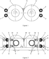
- each casting roller 10, 10' of the twin-roller continuous thin strip casting machine using two brush rollers 1, 1' , 2, 2' arranged at the top and bottom, of which the rotational direction is opposite to that of the casting roller, for cleaning the surface thereof, a linear speed of the casting roller is constant and greater than a rotational speed of the casting roller, and a roller surface cleaning device controls a distance or a pressure between the brush rollers and the casting roller by means of a position control device fixed on a casting roller bearing seat;
- the brush roller is close to the surface of the casting roller and starts cleaning, as casting is processed, the roller surface cleaning device conducts relative displacement adjustment according to a expanding amount of the casting roller to keep a constant pressure between the brush roller and the casting roller;
- the upper and lower brush rollers get close to the roller surface simultaneously and rotate, a rotating speed of the lower roller is 0.2-0.5 time of that of the upper roller, a rotating speed of the upper roller is 1.5-3 times of that of the casting roller, and a pressure applied on the roller surface by the lower roller is 1-2 times larger than that of the upper roller;
- the lower brush roller separates from the contacting with the casting roller surface and keeps an interval of 0.1-1mm therebetween; the rotating speed of the upper roller is 1.5-3 times of that of the casting roller.
- a delivery system stops supplying molten steel
- the lower brush roller gets close to the roller surface and rotates, while the rotating speed of the lower roller is 0.2-0.5 time of that of the upper roller, the rotating speed of the upper roller is 1.5-3 times of that of the casting roller, and the pressure applied on the roller surface by the lower roller is 1-2 times of the pressure applied on the roller surface by the upper roller; a unit pressure applied on the casting roller by the upper roller is 0.1-2.5MPa.
- the upper roller of the brush rollers has a brush hair of which diameter thinner and longer than that of the lower brush roller, the brush hair diameter of the upper roller is ⁇ 0.06- ⁇ 0.28mm, while the brush hair diameter of the lower roller is ⁇ 0.2- ⁇ 0.4mm; the brush hair length of the lower roller is 20-50mm, and that of the upper roller is 40-60mm.
- the brush hair length on same brush roller is equal length or unequal length, and density of the brush hair distributed on the whole roller body of the brush roller is consistent.
- the brush hair of the brush roller uses copper wire or stainless steel wire.
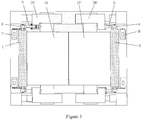
- the device for cleaning a surface of a twin-roller continuous thin strip casting roller of the present invention which comprising: each casting roller 10, 10' is provided with two upper and lower brush rollers 1,1' , 2, 2' , respectively, the brush roller has a length greater than that of the casting roller surface, two brush rollers are mounted at the outer side of the casting roller 10, 10' , both of the brush roller axes are parallel to the casting roller axis, an inner side of the casting roller faces to a molten pool 20, the upper and lower brush roller 1, 1' , 2, 2' are symmetrically arranged at the upper and lower sides of the rotational center line of the casting roller 10, 10' ; bearing seats 3, 3' , 4, 4' supporting both ends of the brush roller 1, 1' , 2, 2' is connected to the bearing seat 30, 30' of the casting roller 10, 10' though a hydraulic drive cylinder 5, 5' , 6, 6' , and one end of the brush roller 1, 1' , 2, 2' is connected with a
Landscapes
- Engineering & Computer Science (AREA)
- Mechanical Engineering (AREA)
- Continuous Casting (AREA)
- Cleaning In General (AREA)
- Casting Support Devices, Ladles, And Melt Control Thereby (AREA)
Claims (11)
- Verfahren zum Reinigen einer Oberfläche einer Walze (10, 10') zum kontinuierlichen Zwei-Rollen-Dünnbandgießen, wobei jede Gießwalze (10, 10') der kontinuierlichen Zwei-Rollen-Dünnbandgießmaschine zwei Bürstenwalzen (1, 1', 2, 2') verwendet, die oben und unten zum Reinigen der Oberfläche davon angeordnet sind, wobei eine Drehrichtung wenigstens einer Bürstenwalze (1, 1', 2, 2') gleich der Gießwalze (10, 10') ist, eine Lineargeschwindigkeit der Gießwalze (10, 10') konstant und größer als eine Drehgeschwindigkeit der Gießwalze (10, 10') ist und eine Walzenoberflächenreinigungsvorrichtung einen Abstand oder einen Druck zwischen den Bürstenwalzen und der Gießwalze (10, 10') mittels einer Positionsregelungsvorrichtung reguliert, die an einem Lagersitz (30, 30') der Gießwalze (10, 10') befestigt ist; wobei sich zu Beginn des Gießens die Bürstenwalze (1, 1', 2, 2') nahe an der Oberfläche der Gießwalze (10, 10') befindet und mit dem Reinigen beginnt, wobei, während das Gießen durchgeführt wird, die Walzenoberflächenreinigungsvorrichtung eine relative Weganpassung gemäß einem Ausdehnungsgrad der Gießwalze (10, 10') durchführt, um einen konstanten Druck zwischen der Bürstenwalze (1, 1') und der Gießwalze (10, 10') aufrechtzuerhalten; wobei während des Walzenoberflächenreinigungsvorgangs Bürstenhaar der Bürstenwalze (1,1') zusammengedrückt wird, sodass es sich um die Walzenoberfläche der Gießwalze (10, 10') unter Einwirkung der Positionsregelungsvorrichtung biegt, wobei die Bürstenwalze (1, 1') teilweise makroskopisch abgeflacht dargestellt ist, wobei ein Mindestabflachungsgrad der Bürstenwalze (1, 1') eine Differenz zwischen einem Bürstenwalzendurchmesser r und einem Mindestdurchmesser rmin nach dem Abflachen ist, das heißt: der Abflachungsgrad Δr = r - rmin, Einheit: mm, wobei der Abflachungsgrad dem 1- bis 10-Fachen einer mittleren Besatzhöhe einer Oberfläche einer Bürstenwalze (1, 1') der Gießwalze (10, 10') entspricht, das heißt: Δr ≤ (1 - 10) • Rc, und die mittlere Besatzhöhe der Walzenoberfläche anhand einer mittleren linearen Höhe Rc einer Walzenoberflächenkontureinheit gemessen wird; (die Definition von Rc stammt aus "Handbook of Mechanical Design", Mechanical Industry Press, 2000, S. 23-307);
wobei sich vor Beginn des Gießvorgangs die obere und untere Bürstenwalze (1, 1') gleichzeitig der Walzenoberfläche nähern und sich drehen, eine Drehgeschwindigkeit der unteren Walze dem 0,2- bis 0,5-Fachen jener der oberen Walze entspricht, eine Drehgeschwindigkeit der oberen Rolle dem 1,5- bis 3-Fachen jener der Gießwalze (10, 10') entspricht und ein auf die Walzenoberfläche durch die untere Walze ausgeübter Druck 1- bis 2-mal größer als jener der oberen Rolle ist;
wobei sich während einer stabilen Gießphase die untere Bürstenwalze (1, 1') von der Oberfläche der Gießwalze (10, 10') abhebt und einen Abstand von 0,1-1 mm dazwischen hält; wobei die Drehgeschwindigkeit der oberen Walze dem 1,5- bis 3-Fachen jener der Gießwalze (10, 10') entspricht;
wobei, wenn der Gießvorgang beendet werden soll, ein Zufuhrsystem aufhört, Stahlschmelze zuzuführen, sich die untere Bürstenwalze (1, 1') der Walzenoberfläche nähert und sich dreht, während die Drehgeschwindigkeit der unteren Walze dem 0,2- bis 0,5-Fachen jener der oberen Walze entspricht, die Drehgeschwindigkeit der oberen Walze dem 1,5- bis 3-Fachen jener der Gießwalze (10, 10') entspricht und der auf die Walzenoberfläche durch die untere Walze ausgeübte Druck dem 1- bis 2-Fachen des auf die Walzenoberfläche durch die obere Walze ausgeübten Drucks entspricht; wobei ein auf die Gießwalze (10, 10') durch die obere Walze ausgeübter Flächendruck 0,1-2,5 MPa beträgt. - Verfahren zum Reinigen einer Oberfläche einer Walze (10, 10') zum kontinuierlichen Zwei-Rollen-Dünnbandgießen nach Anspruch 1, dadurch gekennzeichnet, dass bei Durchführen des Gießens die Walzenoberflächenreinigungsvorrichtung eine entsprechende Weganpassung gemäß einem Ausdehnungsgrad der Gießwalze (10, 10') durchführt, um einen konstanten Druck zwischen der Bürstenwalze (1, 1') und der Gießwalze (10, 10') aufrechtzuerhalten.
- Verfahren zum Reinigen einer Oberfläche einer Walze zum kontinuierlichen Zwei-Rollen-Dünnbandgießen nach Anspruch 1, dadurch gekennzeichnet, dass die obere Walze der Bürstenwalzen (1, 1') ein Bürstenhaar aufweist, dessen Durchmesser dünner und länger als jener der unteren Walze ist, und der maximale Bürstenhaardurchmesser der Bürstenwalzen (1, 1') kleiner als ein mittlerer Durchmesser eines halben Walzenoberflächenbesatzes ist; wobei ein Bürstendurchmesser der oberen Walze typischerweise Φ 0,06 - Φ 0,28 mm beträgt, jener der unteren Walze Φ 0,2 - Φ 0,4 mm beträgt; eine Bürstenhaarlänge der unteren Walze 20-50 mm beträgt und jene der oberen Walze 40-60 mm beträgt.
- Verfahren zum Reinigen einer Oberfläche einer Walze (10, 10') zum kontinuierlichen Zwei-Rollen-Dünnbandgießen nach Anspruch 1, dadurch gekennzeichnet, dass bei Durchführen des Gießens die Walzenoberflächenreinigungsvorrichtung eine entsprechende Weganpassung gemäß einem Ausdehnungsgrad der Gießwalze (10, 10') und einem Abrieb des Bürstenhaars durchführt, um einen auf die Gießwalze (10, 10') durch die Bürstenwalze (1, 1') ausgeübten Druck konstant zu halten; sich während eines Vorgangs zum Reinigen der Walzenoberfläche das Bürstenhaar der Bürstenwalze (1, 1') allmählich verkürzt, ein eingebauter Wegsensor der Positionsregelungsvorrichtung der Bürstenwalze (1, 1') einen Abriebgrad des Bürstenhaars erfasst und ihn an ein Gießmaschinensteuersystem zurückgibt und Letzteres eine Anweisung zum entsprechenden Ändern der Winkelgeschwindigkeit der Bürstenwalze (1, 1') aussendet, um eine Lineargeschwindigkeit eines äußeren Umfangs der Bürstenwalze (1, 1') konstant zu halten.
- Verfahren zum Reinigen einer Oberfläche einer Walze (10, 10') zum kontinuierlichen Zwei-Rollen-Dünnbandgießen nach Anspruch 1 oder 3, dadurch gekennzeichnet, dass die Bürstenhaarlänge derselben Bürstenwalze (1, 1') eine gleiche Länge oder ungleiche Länge ist und die Dichte des auf dem gesamten Walzenkörper der Bürstenwalze (1, 1') verteilten Bürstenhaars einheitlich ist.
- Verfahren zum Reinigen einer Oberfläche einer Walze (10, 10') zum kontinuierlichen Zwei-Rollen-Dünnbandgießen nach Anspruch 1 oder 3, dadurch gekennzeichnet, dass als Bürstenhaar der Bürstenwalze (1, 1') Kupferdraht oder Draht aus nichtrostendem Stahl verwendet wird.
- Vorrichtung zum Reinigen einer Oberfläche einer Walze (10, 10') zum kontinuierlichen Zwei-Rollen-Dünnbandgießen, dadurch gekennzeichnet, dass sie Folgendes umfasst:jede Gießwalze (10, 10') ist mit einer oberen bzw. einer unteren Bürstenwalze versehen, die Bürstenwalze (1, 1') weist eine Länge größer als jene der Oberfläche der Gießwalze (10, 10') auf, zwei Bürstenwalzen sind an der Außenseite der Gießwalze (10, 10') angebracht, die Achsen beider Bürstenwalzen (1, 1') sind parallel zur Achse der Gießwalze (10, 10'), eine Innenseite der Gießwalze (10, 10') ist einem Schmelzbad zugewandt, die obere und untere Bürstenwalze sind symmetrisch an der oberen und unteren Seite der Drehmittellinie der Gießwalze (10, 10') angeordnet; ein Lagersitz (30, 30'), der beide Enden der Bürstenwalze (1, 1') stützt, ist mit dem Lagersitz der Gießwalze durch die eine Positionsregelungsvorrichtung verbunden und ein Ende der Bürstenwalze (1, 1') ist mit einem Untersetzungsgetriebe und einem Motor verbunden;eine Positionsregelungsvorrichtung zum Antreiben der Bürstenwalze (1, 1'), sodass sie sich von der Oberfläche der Gießwalze (10, 10') abhebt oder daran annähert, ist mit einem Wegsensor darin versehen, wobei der Wegsensor elektrisch mit dem kontinuierlichen Dünnbandgießsteuersystem verbunden ist.
- Vorrichtung zum Reinigen einer Oberfläche einer Walze (10, 10') zum kontinuierlichen Zwei-Rollen-Dünnbandgießen nach Anspruch 7, dadurch gekennzeichnet, dass ein Lagersitz (30, 30'), der beide Enden der Bürstenwalze (1, 1') stützt, mit der Positionsregelungsvorrichtung zum Antreiben der Bürstenwalze (1, 1'), sodass sie sich von der Oberfläche der Gießwalze (10, 10') abhebt oder daran annähert, verbunden ist, während die Positionsregelungsvorrichtung an dem Lagersitz (30, 30') der Gießwalze befestigt ist, um eine relative Einbauposition zwischen der Bürstenwalze (1, 1') und der Gießwalze (10, 10') sicherzustellen, und die Positionsregelungsvorrichtung mit einem Wegsensor darin versehen ist, wobei der Wegsensor elektrisch mit dem kontinuierlichen Dünnbandgießsteuersystem verbunden ist; wobei es sich bei der Positionsregelungsvorrichtung um ein Stellglied, das eine geradlinige Bewegung durchführen kann, wie etwa einen Hydraulikzylinder (5, 5'), einen Elektrozylinder, handeln kann.
- Vorrichtung zum Reinigen einer Oberfläche einer Walze (10, 10') zum kontinuierlichen Zwei-Rollen-Dünnbandgießen nach Anspruch 7, dadurch gekennzeichnet, dass die obere Walze der Bürstenwalzen (1, 1') ein Bürstenhaar aufweist, dessen Durchmesser dünner und länger als jener der unteren Walze ist, und die maximalen Bürstenhaardurchmesser der oberen Walze oder unteren Walze allesamt kleiner als der mittlere Durchmesser eines halben Walzenoberflächenbesatzes ist; wobei der Bürstendurchmesser der oberen Walze Φ 0,06 - Φ 0,28 mm beträgt, jener der unteren Walzen Φ 0,2 - Φ 0,4 mm beträgt; die Bürstenlänge der unteren Walze 20-50 mm beträgt und jene der oberen Walze 40-60 mm beträgt.
- Vorrichtung zum Reinigen einer Oberfläche einer Walze (10, 10') zum kontinuierlichen Zwei-Rollen-Dünnbandgießen nach Anspruch 7, dadurch gekennzeichnet, dass die Bürstenhaarlänge derselben Bürstenwalze (1, 1') eine gleiche Länge oder ungleiche Länge ist; und die Dichte des auf dem gesamten Walzenkörper der Bürstenwalze (1, 1') verteilten Bürstenhaars einheitlich ist.
- Vorrichtung zum Reinigen einer Oberfläche einer Walze (10, 10') zum kontinuierlichen Zwei-Rollen-Dünnbandgießen nach Anspruch 7, dadurch gekennzeichnet, dass als Bürstenhaar der Bürstenwalze (1, 1') Kupferdraht oder Draht aus nichtrostendem Stahl verwendet wird.
Applications Claiming Priority (1)
| Application Number | Priority Date | Filing Date | Title |
|---|---|---|---|
| PCT/CN2012/001313 WO2014047746A1 (zh) | 2012-09-27 | 2012-09-27 | 一种双辊薄带连铸辊面清理方法和装置 |
Publications (3)
| Publication Number | Publication Date |
|---|---|
| EP2902134A1 EP2902134A1 (de) | 2015-08-05 |
| EP2902134A4 EP2902134A4 (de) | 2016-06-08 |
| EP2902134B1 true EP2902134B1 (de) | 2018-06-20 |
Family
ID=50386749
Family Applications (1)
| Application Number | Title | Priority Date | Filing Date |
|---|---|---|---|
| EP12885417.1A Active EP2902134B1 (de) | 2012-09-27 | 2012-09-27 | Verfahren und vorrichtung zur reinigung einer doppelwalze, eines dünnen bandes und einer strangguss-walzenfläche |
Country Status (5)
| Country | Link |
|---|---|
| US (1) | US9770756B2 (de) |
| EP (1) | EP2902134B1 (de) |
| JP (1) | JP6162247B2 (de) |
| KR (1) | KR20150048203A (de) |
| WO (1) | WO2014047746A1 (de) |
Families Citing this family (12)
| Publication number | Priority date | Publication date | Assignee | Title |
|---|---|---|---|---|
| KR101899672B1 (ko) * | 2016-12-15 | 2018-09-17 | 주식회사 포스코 | 브러쉬 롤 장치와 이를 사용하는 박판 주조 장치 |
| WO2018119551A1 (zh) * | 2016-12-26 | 2018-07-05 | 宝山钢铁股份有限公司 | 铸辊辊面清理装置和方法 |
| CN106914592A (zh) * | 2017-04-13 | 2017-07-04 | 朗峰新材料科技股份有限公司 | 一种移动式纳米晶带材制备设备 |
| CN110038831A (zh) * | 2019-04-24 | 2019-07-23 | 万威 | 一种清洗效果好的圆柱形铸件清洗装置 |
| CN112643004B (zh) * | 2019-10-10 | 2022-07-19 | 青岛正望新材料股份有限公司 | 一种双辊薄带连铸用浇铸系统及布流水口 |
| US10975908B1 (en) * | 2019-10-29 | 2021-04-13 | Schaeffler Monitoring Services Gmbh | Method and device for monitoring a bearing clearance of roller bearings |
| CN112058730A (zh) * | 2020-07-24 | 2020-12-11 | 张家港扬子江冷轧板有限公司 | 一种可移动清理辊面的刷辊及使用方法 |
| CN112157229A (zh) * | 2020-09-07 | 2021-01-01 | 东北大学 | 一种薄带连铸的辊面清理装置及其控制方法和控制装置 |
| CN112157230A (zh) * | 2020-09-07 | 2021-01-01 | 东北大学 | 一种双辊薄带连铸辊面清理装置 |
| CN114472237B (zh) * | 2021-12-10 | 2023-05-02 | 无锡市蠡湖铸业有限公司 | 一种叠浇注系统用可调向净化的整合装置 |
| CN114309516B (zh) * | 2021-12-29 | 2023-12-05 | 深圳市以凡泰科技有限公司 | 镍钛合金高效高通量连铸装置及方法 |
| CN115228789B (zh) * | 2022-09-23 | 2022-12-20 | 济南和拓自动化科技有限公司 | 刷辊式清洁系统 |
Family Cites Families (14)
| Publication number | Priority date | Publication date | Assignee | Title |
|---|---|---|---|---|
| US4793400A (en) * | 1987-11-24 | 1988-12-27 | Battelle Development Corporation | Double brushing of grooved casting wheels |
| JPH0716770B2 (ja) | 1990-02-02 | 1995-03-01 | 新日本製鐵株式会社 | 薄肉鋳片の連続鋳造装置 |
| GB2262434A (en) | 1991-12-13 | 1993-06-23 | Ishikawajima Harima Heavy Ind | A brush assembly suitable for cleaning irregularly shaped surfaces such as hot metal casting rolls |
| JP2971241B2 (ja) * | 1992-04-28 | 1999-11-02 | 三菱重工業株式会社 | 双ドラム式連続鋳造装置 |
| JP3230849B2 (ja) | 1992-08-15 | 2001-11-19 | 株式会社リコー | 画像処理装置 |
| JPH0929394A (ja) * | 1995-07-25 | 1997-02-04 | Nippon Steel Corp | 薄帯状鋳片鋳造用冷却ドラムの清浄化方法 |
| JPH0929393A (ja) | 1995-07-25 | 1997-02-04 | Nippon Steel Corp | 薄帯状鋳片鋳造用冷却ドラムの清浄化方法及び装置 |
| US6886623B2 (en) * | 1998-06-17 | 2005-05-03 | Castrip Llc | Strip casting apparatus |
| ATE375833T1 (de) | 2000-05-12 | 2007-11-15 | Nippon Steel Corp | Gekühlte giesswalze zum kontinuierlichen stranggiessen von dünnen produkten und stranggiessverfahren |
| US8063375B2 (en) | 2007-06-22 | 2011-11-22 | Intel-Ge Care Innovations Llc | Sensible motion detector |
| KR100899706B1 (ko) * | 2007-09-28 | 2009-05-28 | 주식회사 포스코 | 박판주조기를 이용한 오스테나이트계 스테인레스 강판의제조방법 |
| CN201136046Y (zh) * | 2007-12-21 | 2008-10-22 | 宝山钢铁股份有限公司 | 一种双辊薄带连铸辊面清理装置 |
| WO2010059992A2 (en) * | 2008-11-20 | 2010-05-27 | Ihi Corporation | Brush roll for casting roll |
| CN102950276B (zh) * | 2011-08-30 | 2014-10-01 | 宝山钢铁股份有限公司 | 一种双辊薄带连铸辊面清理方法和装置 |
-
2012
- 2012-09-27 EP EP12885417.1A patent/EP2902134B1/de active Active
- 2012-09-27 KR KR1020157007705A patent/KR20150048203A/ko not_active Ceased
- 2012-09-27 US US14/429,735 patent/US9770756B2/en active Active
- 2012-09-27 WO PCT/CN2012/001313 patent/WO2014047746A1/zh not_active Ceased
- 2012-09-27 JP JP2015533390A patent/JP6162247B2/ja active Active
Non-Patent Citations (1)
| Title |
|---|
| None * |
Also Published As
| Publication number | Publication date |
|---|---|
| EP2902134A1 (de) | 2015-08-05 |
| WO2014047746A1 (zh) | 2014-04-03 |
| JP6162247B2 (ja) | 2017-07-12 |
| KR20150048203A (ko) | 2015-05-06 |
| EP2902134A4 (de) | 2016-06-08 |
| JP2015530256A (ja) | 2015-10-15 |
| US9770756B2 (en) | 2017-09-26 |
| US20150231693A1 (en) | 2015-08-20 |
Similar Documents
| Publication | Publication Date | Title |
|---|---|---|
| EP2902134B1 (de) | Verfahren und vorrichtung zur reinigung einer doppelwalze, eines dünnen bandes und einer strangguss-walzenfläche | |
| CN102950276B (zh) | 一种双辊薄带连铸辊面清理方法和装置 | |
| WO2024066742A1 (zh) | 一种改善热轧薄带钢的局部高点的方法 | |
| CN101376164B (zh) | 一种双辊薄带连铸冷却辊辊形控制方法 | |
| CN201436107U (zh) | 一种双辊薄带连铸辊面清理装置 | |
| CN105149562B (zh) | 一种清理双辊薄带连铸辊面的方法 | |
| US8763679B2 (en) | Casting roll for a two-roll casting device and two-roll casting device | |
| CN201136046Y (zh) | 一种双辊薄带连铸辊面清理装置 | |
| KR20100110802A (ko) | 박판 주조 스트립에서 열 유속의 국부적 제어 방법 및 장치 | |
| CN103831413B (zh) | 一种对带倒角连铸坯进行角部变形的支撑辊装置和方法 | |
| JP5104943B2 (ja) | ロール研磨装置 | |
| CN100425395C (zh) | 一种阳极铜球的制备方法及其装置 | |
| CN201862644U (zh) | 一种带钢表面刷洗装置 | |
| JP3659208B2 (ja) | MgまたはMg合金帯板の製造方法および製造装置 | |
| CN114515823A (zh) | 一种双辊薄带连铸辊面清理方法和装置 | |
| CN112157230A (zh) | 一种双辊薄带连铸辊面清理装置 | |
| CN118287321A (zh) | 一种提高取向硅钢表面涂层均匀度的涂层辊系 | |
| JP4234827B2 (ja) | 金属ストリップ鋳造方法、金属ストリップを鋳造するストリップ鋳造装置、及び双ロールストリップ鋳造装置 | |
| JP4952200B2 (ja) | ロール研磨装置 | |
| CN114054533A (zh) | 一种高材料利用率的挤压坯及其制造方法 | |
| JP5950192B2 (ja) | マグネシウム合金コイル材の製造装置 | |
| KR101243253B1 (ko) | 쌍롤식 박판 주조 장치의 주조롤 | |
| CN106552907B (zh) | 提高铸带表面质量的装置以及方法 | |
| CN106552911B (zh) | 薄带连铸混杂毛辊面的清理装置以及清理方法 | |
| CN1111177A (zh) | 一种薄带连铸机 |
Legal Events
| Date | Code | Title | Description |
|---|---|---|---|
| PUAI | Public reference made under article 153(3) epc to a published international application that has entered the european phase |
Free format text: ORIGINAL CODE: 0009012 |
|
| 17P | Request for examination filed |
Effective date: 20150223 |
|
| AK | Designated contracting states |
Kind code of ref document: A1 Designated state(s): AL AT BE BG CH CY CZ DE DK EE ES FI FR GB GR HR HU IE IS IT LI LT LU LV MC MK MT NL NO PL PT RO RS SE SI SK SM TR |
|
| AX | Request for extension of the european patent |
Extension state: BA ME |
|
| DAX | Request for extension of the european patent (deleted) | ||
| RA4 | Supplementary search report drawn up and despatched (corrected) |
Effective date: 20160509 |
|
| RIC1 | Information provided on ipc code assigned before grant |
Ipc: B22D 11/06 20060101AFI20160502BHEP Ipc: B22D 43/00 20060101ALI20160502BHEP |
|
| GRAP | Despatch of communication of intention to grant a patent |
Free format text: ORIGINAL CODE: EPIDOSNIGR1 |
|
| INTG | Intention to grant announced |
Effective date: 20180326 |
|
| GRAS | Grant fee paid |
Free format text: ORIGINAL CODE: EPIDOSNIGR3 |
|
| GRAA | (expected) grant |
Free format text: ORIGINAL CODE: 0009210 |
|
| AK | Designated contracting states |
Kind code of ref document: B1 Designated state(s): AL AT BE BG CH CY CZ DE DK EE ES FI FR GB GR HR HU IE IS IT LI LT LU LV MC MK MT NL NO PL PT RO RS SE SI SK SM TR |
|
| REG | Reference to a national code |
Ref country code: GB Ref legal event code: FG4D |
|
| REG | Reference to a national code |
Ref country code: IE Ref legal event code: FG4D |
|
| REG | Reference to a national code |
Ref country code: AT Ref legal event code: REF Ref document number: 1010215 Country of ref document: AT Kind code of ref document: T Effective date: 20180715 |
|
| REG | Reference to a national code |
Ref country code: DE Ref legal event code: R096 Ref document number: 602012047752 Country of ref document: DE |
|
| REG | Reference to a national code |
Ref country code: FR Ref legal event code: PLFP Year of fee payment: 7 |
|
| REG | Reference to a national code |
Ref country code: NL Ref legal event code: MP Effective date: 20180620 |
|
| PG25 | Lapsed in a contracting state [announced via postgrant information from national office to epo] |
Ref country code: BG Free format text: LAPSE BECAUSE OF FAILURE TO SUBMIT A TRANSLATION OF THE DESCRIPTION OR TO PAY THE FEE WITHIN THE PRESCRIBED TIME-LIMIT Effective date: 20180920 Ref country code: FI Free format text: LAPSE BECAUSE OF FAILURE TO SUBMIT A TRANSLATION OF THE DESCRIPTION OR TO PAY THE FEE WITHIN THE PRESCRIBED TIME-LIMIT Effective date: 20180620 Ref country code: NO Free format text: LAPSE BECAUSE OF FAILURE TO SUBMIT A TRANSLATION OF THE DESCRIPTION OR TO PAY THE FEE WITHIN THE PRESCRIBED TIME-LIMIT Effective date: 20180920 Ref country code: SE Free format text: LAPSE BECAUSE OF FAILURE TO SUBMIT A TRANSLATION OF THE DESCRIPTION OR TO PAY THE FEE WITHIN THE PRESCRIBED TIME-LIMIT Effective date: 20180620 Ref country code: LT Free format text: LAPSE BECAUSE OF FAILURE TO SUBMIT A TRANSLATION OF THE DESCRIPTION OR TO PAY THE FEE WITHIN THE PRESCRIBED TIME-LIMIT Effective date: 20180620 |
|
| REG | Reference to a national code |
Ref country code: LT Ref legal event code: MG4D |
|
| PG25 | Lapsed in a contracting state [announced via postgrant information from national office to epo] |
Ref country code: GR Free format text: LAPSE BECAUSE OF FAILURE TO SUBMIT A TRANSLATION OF THE DESCRIPTION OR TO PAY THE FEE WITHIN THE PRESCRIBED TIME-LIMIT Effective date: 20180921 Ref country code: HR Free format text: LAPSE BECAUSE OF FAILURE TO SUBMIT A TRANSLATION OF THE DESCRIPTION OR TO PAY THE FEE WITHIN THE PRESCRIBED TIME-LIMIT Effective date: 20180620 Ref country code: LV Free format text: LAPSE BECAUSE OF FAILURE TO SUBMIT A TRANSLATION OF THE DESCRIPTION OR TO PAY THE FEE WITHIN THE PRESCRIBED TIME-LIMIT Effective date: 20180620 Ref country code: RS Free format text: LAPSE BECAUSE OF FAILURE TO SUBMIT A TRANSLATION OF THE DESCRIPTION OR TO PAY THE FEE WITHIN THE PRESCRIBED TIME-LIMIT Effective date: 20180620 |
|
| REG | Reference to a national code |
Ref country code: AT Ref legal event code: MK05 Ref document number: 1010215 Country of ref document: AT Kind code of ref document: T Effective date: 20180620 |
|
| PG25 | Lapsed in a contracting state [announced via postgrant information from national office to epo] |
Ref country code: NL Free format text: LAPSE BECAUSE OF FAILURE TO SUBMIT A TRANSLATION OF THE DESCRIPTION OR TO PAY THE FEE WITHIN THE PRESCRIBED TIME-LIMIT Effective date: 20180620 |
|
| PG25 | Lapsed in a contracting state [announced via postgrant information from national office to epo] |
Ref country code: RO Free format text: LAPSE BECAUSE OF FAILURE TO SUBMIT A TRANSLATION OF THE DESCRIPTION OR TO PAY THE FEE WITHIN THE PRESCRIBED TIME-LIMIT Effective date: 20180620 Ref country code: SK Free format text: LAPSE BECAUSE OF FAILURE TO SUBMIT A TRANSLATION OF THE DESCRIPTION OR TO PAY THE FEE WITHIN THE PRESCRIBED TIME-LIMIT Effective date: 20180620 Ref country code: CZ Free format text: LAPSE BECAUSE OF FAILURE TO SUBMIT A TRANSLATION OF THE DESCRIPTION OR TO PAY THE FEE WITHIN THE PRESCRIBED TIME-LIMIT Effective date: 20180620 Ref country code: IS Free format text: LAPSE BECAUSE OF FAILURE TO SUBMIT A TRANSLATION OF THE DESCRIPTION OR TO PAY THE FEE WITHIN THE PRESCRIBED TIME-LIMIT Effective date: 20181020 Ref country code: AT Free format text: LAPSE BECAUSE OF FAILURE TO SUBMIT A TRANSLATION OF THE DESCRIPTION OR TO PAY THE FEE WITHIN THE PRESCRIBED TIME-LIMIT Effective date: 20180620 Ref country code: EE Free format text: LAPSE BECAUSE OF FAILURE TO SUBMIT A TRANSLATION OF THE DESCRIPTION OR TO PAY THE FEE WITHIN THE PRESCRIBED TIME-LIMIT Effective date: 20180620 Ref country code: PL Free format text: LAPSE BECAUSE OF FAILURE TO SUBMIT A TRANSLATION OF THE DESCRIPTION OR TO PAY THE FEE WITHIN THE PRESCRIBED TIME-LIMIT Effective date: 20180620 |
|
| PG25 | Lapsed in a contracting state [announced via postgrant information from national office to epo] |
Ref country code: SM Free format text: LAPSE BECAUSE OF FAILURE TO SUBMIT A TRANSLATION OF THE DESCRIPTION OR TO PAY THE FEE WITHIN THE PRESCRIBED TIME-LIMIT Effective date: 20180620 Ref country code: ES Free format text: LAPSE BECAUSE OF FAILURE TO SUBMIT A TRANSLATION OF THE DESCRIPTION OR TO PAY THE FEE WITHIN THE PRESCRIBED TIME-LIMIT Effective date: 20180620 |
|
| REG | Reference to a national code |
Ref country code: DE Ref legal event code: R097 Ref document number: 602012047752 Country of ref document: DE |
|
| PLBE | No opposition filed within time limit |
Free format text: ORIGINAL CODE: 0009261 |
|
| STAA | Information on the status of an ep patent application or granted ep patent |
Free format text: STATUS: NO OPPOSITION FILED WITHIN TIME LIMIT |
|
| PG25 | Lapsed in a contracting state [announced via postgrant information from national office to epo] |
Ref country code: MC Free format text: LAPSE BECAUSE OF FAILURE TO SUBMIT A TRANSLATION OF THE DESCRIPTION OR TO PAY THE FEE WITHIN THE PRESCRIBED TIME-LIMIT Effective date: 20180620 |
|
| REG | Reference to a national code |
Ref country code: CH Ref legal event code: PL |
|
| GBPC | Gb: european patent ceased through non-payment of renewal fee |
Effective date: 20180927 |
|
| 26N | No opposition filed |
Effective date: 20190321 |
|
| PG25 | Lapsed in a contracting state [announced via postgrant information from national office to epo] |
Ref country code: DK Free format text: LAPSE BECAUSE OF FAILURE TO SUBMIT A TRANSLATION OF THE DESCRIPTION OR TO PAY THE FEE WITHIN THE PRESCRIBED TIME-LIMIT Effective date: 20180620 |
|
| REG | Reference to a national code |
Ref country code: BE Ref legal event code: MM Effective date: 20180930 |
|
| REG | Reference to a national code |
Ref country code: IE Ref legal event code: MM4A |
|
| PG25 | Lapsed in a contracting state [announced via postgrant information from national office to epo] |
Ref country code: LU Free format text: LAPSE BECAUSE OF NON-PAYMENT OF DUE FEES Effective date: 20180927 |
|
| PG25 | Lapsed in a contracting state [announced via postgrant information from national office to epo] |
Ref country code: IE Free format text: LAPSE BECAUSE OF NON-PAYMENT OF DUE FEES Effective date: 20180927 |
|
| PG25 | Lapsed in a contracting state [announced via postgrant information from national office to epo] |
Ref country code: BE Free format text: LAPSE BECAUSE OF NON-PAYMENT OF DUE FEES Effective date: 20180930 Ref country code: SI Free format text: LAPSE BECAUSE OF FAILURE TO SUBMIT A TRANSLATION OF THE DESCRIPTION OR TO PAY THE FEE WITHIN THE PRESCRIBED TIME-LIMIT Effective date: 20180620 Ref country code: LI Free format text: LAPSE BECAUSE OF NON-PAYMENT OF DUE FEES Effective date: 20180930 Ref country code: CH Free format text: LAPSE BECAUSE OF NON-PAYMENT OF DUE FEES Effective date: 20180930 |
|
| PG25 | Lapsed in a contracting state [announced via postgrant information from national office to epo] |
Ref country code: GB Free format text: LAPSE BECAUSE OF NON-PAYMENT OF DUE FEES Effective date: 20180927 |
|
| PG25 | Lapsed in a contracting state [announced via postgrant information from national office to epo] |
Ref country code: AL Free format text: LAPSE BECAUSE OF FAILURE TO SUBMIT A TRANSLATION OF THE DESCRIPTION OR TO PAY THE FEE WITHIN THE PRESCRIBED TIME-LIMIT Effective date: 20180620 |
|
| PG25 | Lapsed in a contracting state [announced via postgrant information from national office to epo] |
Ref country code: MT Free format text: LAPSE BECAUSE OF NON-PAYMENT OF DUE FEES Effective date: 20180927 |
|
| PG25 | Lapsed in a contracting state [announced via postgrant information from national office to epo] |
Ref country code: TR Free format text: LAPSE BECAUSE OF FAILURE TO SUBMIT A TRANSLATION OF THE DESCRIPTION OR TO PAY THE FEE WITHIN THE PRESCRIBED TIME-LIMIT Effective date: 20180620 |
|
| PG25 | Lapsed in a contracting state [announced via postgrant information from national office to epo] |
Ref country code: PT Free format text: LAPSE BECAUSE OF FAILURE TO SUBMIT A TRANSLATION OF THE DESCRIPTION OR TO PAY THE FEE WITHIN THE PRESCRIBED TIME-LIMIT Effective date: 20180620 |
|
| PG25 | Lapsed in a contracting state [announced via postgrant information from national office to epo] |
Ref country code: CY Free format text: LAPSE BECAUSE OF FAILURE TO SUBMIT A TRANSLATION OF THE DESCRIPTION OR TO PAY THE FEE WITHIN THE PRESCRIBED TIME-LIMIT Effective date: 20180620 Ref country code: HU Free format text: LAPSE BECAUSE OF FAILURE TO SUBMIT A TRANSLATION OF THE DESCRIPTION OR TO PAY THE FEE WITHIN THE PRESCRIBED TIME-LIMIT; INVALID AB INITIO Effective date: 20120927 Ref country code: MK Free format text: LAPSE BECAUSE OF NON-PAYMENT OF DUE FEES Effective date: 20180620 |
|
| PGFP | Annual fee paid to national office [announced via postgrant information from national office to epo] |
Ref country code: DE Payment date: 20250916 Year of fee payment: 14 |
|
| PGFP | Annual fee paid to national office [announced via postgrant information from national office to epo] |
Ref country code: IT Payment date: 20250910 Year of fee payment: 14 |
|
| PGFP | Annual fee paid to national office [announced via postgrant information from national office to epo] |
Ref country code: FR Payment date: 20250929 Year of fee payment: 14 |