EP2899558B1 - Apparatus for estimating depth of discharge (dod) of secondary battery - Google Patents
Apparatus for estimating depth of discharge (dod) of secondary battery Download PDFInfo
- Publication number
- EP2899558B1 EP2899558B1 EP13860399.8A EP13860399A EP2899558B1 EP 2899558 B1 EP2899558 B1 EP 2899558B1 EP 13860399 A EP13860399 A EP 13860399A EP 2899558 B1 EP2899558 B1 EP 2899558B1
- Authority
- EP
- European Patent Office
- Prior art keywords
- secondary battery
- dod
- voltage
- cathode material
- inflection point
- Prior art date
- Legal status (The legal status is an assumption and is not a legal conclusion. Google has not performed a legal analysis and makes no representation as to the accuracy of the status listed.)
- Active
Links
- 239000010406 cathode material Substances 0.000 claims description 108
- 230000008859 change Effects 0.000 claims description 91
- 150000002500 ions Chemical class 0.000 claims description 41
- 238000000034 method Methods 0.000 claims description 24
- 230000007704 transition Effects 0.000 claims description 23
- 238000007599 discharging Methods 0.000 claims description 21
- 238000003860 storage Methods 0.000 claims description 15
- 238000004891 communication Methods 0.000 claims description 12
- 230000006870 function Effects 0.000 description 53
- 229910052744 lithium Inorganic materials 0.000 description 26
- 229910052493 LiFePO4 Inorganic materials 0.000 description 22
- WHXSMMKQMYFTQS-UHFFFAOYSA-N Lithium Chemical compound [Li] WHXSMMKQMYFTQS-UHFFFAOYSA-N 0.000 description 20
- 238000002474 experimental method Methods 0.000 description 13
- PXHVJJICTQNCMI-UHFFFAOYSA-N nickel Substances [Ni] PXHVJJICTQNCMI-UHFFFAOYSA-N 0.000 description 13
- 239000011572 manganese Substances 0.000 description 12
- 229910052710 silicon Inorganic materials 0.000 description 12
- 229910052720 vanadium Inorganic materials 0.000 description 12
- 229910052750 molybdenum Inorganic materials 0.000 description 11
- 229910052759 nickel Inorganic materials 0.000 description 10
- 229910012733 LiCo1/3Mn1/3Ni1/3O2 Inorganic materials 0.000 description 9
- 229910052782 aluminium Inorganic materials 0.000 description 9
- 229910052804 chromium Inorganic materials 0.000 description 9
- 229910052749 magnesium Inorganic materials 0.000 description 9
- 229910052748 manganese Inorganic materials 0.000 description 9
- 230000008929 regeneration Effects 0.000 description 9
- 238000011069 regeneration method Methods 0.000 description 9
- 229910052719 titanium Inorganic materials 0.000 description 9
- 239000003792 electrolyte Substances 0.000 description 7
- 238000002156 mixing Methods 0.000 description 7
- HBBGRARXTFLTSG-UHFFFAOYSA-N Lithium ion Chemical compound [Li+] HBBGRARXTFLTSG-UHFFFAOYSA-N 0.000 description 6
- 238000013213 extrapolation Methods 0.000 description 6
- 229910052742 iron Inorganic materials 0.000 description 6
- XEEYBQQBJWHFJM-UHFFFAOYSA-N iron Substances [Fe] XEEYBQQBJWHFJM-UHFFFAOYSA-N 0.000 description 6
- 229910001416 lithium ion Inorganic materials 0.000 description 6
- 238000005259 measurement Methods 0.000 description 6
- 229910052779 Neodymium Inorganic materials 0.000 description 5
- 239000000126 substance Substances 0.000 description 5
- 229910015228 Ni1/3Mn1/3CO1/3 Inorganic materials 0.000 description 4
- 229910019142 PO4 Inorganic materials 0.000 description 4
- 150000001339 alkali metal compounds Chemical class 0.000 description 4
- 238000004364 calculation method Methods 0.000 description 4
- 239000000463 material Substances 0.000 description 4
- 230000003647 oxidation Effects 0.000 description 4
- 238000007254 oxidation reaction Methods 0.000 description 4
- NBIIXXVUZAFLBC-UHFFFAOYSA-K phosphate Chemical compound [O-]P([O-])([O-])=O NBIIXXVUZAFLBC-UHFFFAOYSA-K 0.000 description 4
- 239000010452 phosphate Substances 0.000 description 4
- 229910052726 zirconium Inorganic materials 0.000 description 4
- 229910012735 LiCo1/3Ni1/3Mn1/3O2 Inorganic materials 0.000 description 3
- 229910052787 antimony Inorganic materials 0.000 description 3
- 229910052785 arsenic Inorganic materials 0.000 description 3
- 238000006056 electrooxidation reaction Methods 0.000 description 3
- 229910052732 germanium Inorganic materials 0.000 description 3
- 238000009830 intercalation Methods 0.000 description 3
- 239000010410 layer Substances 0.000 description 3
- 230000007246 mechanism Effects 0.000 description 3
- 230000008569 process Effects 0.000 description 3
- 238000006722 reduction reaction Methods 0.000 description 3
- 229910052717 sulfur Inorganic materials 0.000 description 3
- OKTJSMMVPCPJKN-UHFFFAOYSA-N Carbon Chemical compound [C] OKTJSMMVPCPJKN-UHFFFAOYSA-N 0.000 description 2
- 229910009939 Li2M2O3 Inorganic materials 0.000 description 2
- 229910012682 Li3M2(PO4)3 Inorganic materials 0.000 description 2
- 229910010187 LiaM1xFe1-xM2yP1-yM3zO4-z Inorganic materials 0.000 description 2
- 229910010190 LiaM1xFe1-xM2yP1-yM3zO4−z Inorganic materials 0.000 description 2
- 229910010183 LiaM1xFe1−xM2yP1−yM3zO4−z Inorganic materials 0.000 description 2
- 229910014981 LiaNixCoyMnzO2 Inorganic materials 0.000 description 2
- 229910002097 Lithium manganese(III,IV) oxide Inorganic materials 0.000 description 2
- 239000000654 additive Substances 0.000 description 2
- 239000010405 anode material Substances 0.000 description 2
- 230000006399 behavior Effects 0.000 description 2
- 229910052791 calcium Inorganic materials 0.000 description 2
- 239000006182 cathode active material Substances 0.000 description 2
- 238000006243 chemical reaction Methods 0.000 description 2
- 239000011247 coating layer Substances 0.000 description 2
- 150000001875 compounds Chemical class 0.000 description 2
- 229910052802 copper Inorganic materials 0.000 description 2
- 230000007423 decrease Effects 0.000 description 2
- 238000009831 deintercalation Methods 0.000 description 2
- 238000010586 diagram Methods 0.000 description 2
- IEJIGPNLZYLLBP-UHFFFAOYSA-N dimethyl carbonate Chemical compound COC(=O)OC IEJIGPNLZYLLBP-UHFFFAOYSA-N 0.000 description 2
- 238000003487 electrochemical reaction Methods 0.000 description 2
- 238000004146 energy storage Methods 0.000 description 2
- JBTWLSYIZRCDFO-UHFFFAOYSA-N ethyl methyl carbonate Chemical compound CCOC(=O)OC JBTWLSYIZRCDFO-UHFFFAOYSA-N 0.000 description 2
- 229910052736 halogen Inorganic materials 0.000 description 2
- 150000002367 halogens Chemical class 0.000 description 2
- 230000002687 intercalation Effects 0.000 description 2
- 238000004519 manufacturing process Methods 0.000 description 2
- CQDGTJPVBWZJAZ-UHFFFAOYSA-N monoethyl carbonate Chemical compound CCOC(O)=O CQDGTJPVBWZJAZ-UHFFFAOYSA-N 0.000 description 2
- 230000007935 neutral effect Effects 0.000 description 2
- 230000003287 optical effect Effects 0.000 description 2
- 229910052700 potassium Inorganic materials 0.000 description 2
- 230000004044 response Effects 0.000 description 2
- 229910052707 ruthenium Inorganic materials 0.000 description 2
- 229910052706 scandium Inorganic materials 0.000 description 2
- NDVLTYZPCACLMA-UHFFFAOYSA-N silver oxide Chemical compound [O-2].[Ag+].[Ag+] NDVLTYZPCACLMA-UHFFFAOYSA-N 0.000 description 2
- 229910052708 sodium Inorganic materials 0.000 description 2
- 229910052725 zinc Inorganic materials 0.000 description 2
- 239000011701 zinc Substances 0.000 description 2
- KRHYYFGTRYWZRS-UHFFFAOYSA-M Fluoride anion Chemical compound [F-] KRHYYFGTRYWZRS-UHFFFAOYSA-M 0.000 description 1
- 229910012453 Li3Fe2(PO4)3 Inorganic materials 0.000 description 1
- 229910015004 LiMnxFeyPO4 Inorganic materials 0.000 description 1
- 229910003005 LiNiO2 Inorganic materials 0.000 description 1
- 229910001290 LiPF6 Inorganic materials 0.000 description 1
- 229910014638 LiaNib Inorganic materials 0.000 description 1
- 229910016774 Ni0.5Mn0.3Co0.2 Inorganic materials 0.000 description 1
- ZRXYMHTYEQQBLN-UHFFFAOYSA-N [Br].[Zn] Chemical compound [Br].[Zn] ZRXYMHTYEQQBLN-UHFFFAOYSA-N 0.000 description 1
- 239000002253 acid Substances 0.000 description 1
- 238000003915 air pollution Methods 0.000 description 1
- 238000004458 analytical method Methods 0.000 description 1
- 239000006183 anode active material Substances 0.000 description 1
- 238000013459 approach Methods 0.000 description 1
- 238000000429 assembly Methods 0.000 description 1
- 230000000712 assembly Effects 0.000 description 1
- 239000002585 base Substances 0.000 description 1
- 239000011230 binding agent Substances 0.000 description 1
- OJIJEKBXJYRIBZ-UHFFFAOYSA-N cadmium nickel Chemical compound [Ni].[Cd] OJIJEKBXJYRIBZ-UHFFFAOYSA-N 0.000 description 1
- 229910052799 carbon Inorganic materials 0.000 description 1
- 239000004020 conductor Substances 0.000 description 1
- 238000001514 detection method Methods 0.000 description 1
- 230000006866 deterioration Effects 0.000 description 1
- 238000009792 diffusion process Methods 0.000 description 1
- 238000009826 distribution Methods 0.000 description 1
- 230000000694 effects Effects 0.000 description 1
- 230000005611 electricity Effects 0.000 description 1
- 238000005516 engineering process Methods 0.000 description 1
- 230000001747 exhibiting effect Effects 0.000 description 1
- 239000002803 fossil fuel Substances 0.000 description 1
- 239000010439 graphite Substances 0.000 description 1
- 229910002804 graphite Inorganic materials 0.000 description 1
- 239000010954 inorganic particle Substances 0.000 description 1
- UGKDIUIOSMUOAW-UHFFFAOYSA-N iron nickel Chemical compound [Fe].[Ni] UGKDIUIOSMUOAW-UHFFFAOYSA-N 0.000 description 1
- 239000004973 liquid crystal related substance Substances 0.000 description 1
- 238000013507 mapping Methods 0.000 description 1
- 238000013178 mathematical model Methods 0.000 description 1
- 229910052987 metal hydride Inorganic materials 0.000 description 1
- 239000012046 mixed solvent Substances 0.000 description 1
- 238000010295 mobile communication Methods 0.000 description 1
- 238000012986 modification Methods 0.000 description 1
- 230000004048 modification Effects 0.000 description 1
- 238000012544 monitoring process Methods 0.000 description 1
- -1 nickel metal hydride Chemical class 0.000 description 1
- QELJHCBNGDEXLD-UHFFFAOYSA-N nickel zinc Chemical compound [Ni].[Zn] QELJHCBNGDEXLD-UHFFFAOYSA-N 0.000 description 1
- 229920000098 polyolefin Polymers 0.000 description 1
- 238000012545 processing Methods 0.000 description 1
- 230000002441 reversible effect Effects 0.000 description 1
- 238000005070 sampling Methods 0.000 description 1
- 239000004065 semiconductor Substances 0.000 description 1
- 229910001923 silver oxide Inorganic materials 0.000 description 1
- SZKTYYIADWRVSA-UHFFFAOYSA-N zinc manganese(2+) oxygen(2-) Chemical compound [O--].[O--].[Mn++].[Zn++] SZKTYYIADWRVSA-UHFFFAOYSA-N 0.000 description 1
Images


Classifications
-
- G—PHYSICS
- G01—MEASURING; TESTING
- G01R—MEASURING ELECTRIC VARIABLES; MEASURING MAGNETIC VARIABLES
- G01R31/00—Arrangements for testing electric properties; Arrangements for locating electric faults; Arrangements for electrical testing characterised by what is being tested not provided for elsewhere
- G01R31/36—Arrangements for testing, measuring or monitoring the electrical condition of accumulators or electric batteries, e.g. capacity or state of charge [SoC]
- G01R31/367—Software therefor, e.g. for battery testing using modelling or look-up tables
-
- G—PHYSICS
- G01—MEASURING; TESTING
- G01R—MEASURING ELECTRIC VARIABLES; MEASURING MAGNETIC VARIABLES
- G01R19/00—Arrangements for measuring currents or voltages or for indicating presence or sign thereof
- G01R19/165—Indicating that current or voltage is either above or below a predetermined value or within or outside a predetermined range of values
-
- G—PHYSICS
- G01—MEASURING; TESTING
- G01R—MEASURING ELECTRIC VARIABLES; MEASURING MAGNETIC VARIABLES
- G01R31/00—Arrangements for testing electric properties; Arrangements for locating electric faults; Arrangements for electrical testing characterised by what is being tested not provided for elsewhere
- G01R31/36—Arrangements for testing, measuring or monitoring the electrical condition of accumulators or electric batteries, e.g. capacity or state of charge [SoC]
- G01R31/382—Arrangements for monitoring battery or accumulator variables, e.g. SoC
- G01R31/3835—Arrangements for monitoring battery or accumulator variables, e.g. SoC involving only voltage measurements
-
- H—ELECTRICITY
- H01—ELECTRIC ELEMENTS
- H01M—PROCESSES OR MEANS, e.g. BATTERIES, FOR THE DIRECT CONVERSION OF CHEMICAL ENERGY INTO ELECTRICAL ENERGY
- H01M10/00—Secondary cells; Manufacture thereof
- H01M10/42—Methods or arrangements for servicing or maintenance of secondary cells or secondary half-cells
- H01M10/48—Accumulators combined with arrangements for measuring, testing or indicating the condition of cells, e.g. the level or density of the electrolyte
-
- H—ELECTRICITY
- H01—ELECTRIC ELEMENTS
- H01M—PROCESSES OR MEANS, e.g. BATTERIES, FOR THE DIRECT CONVERSION OF CHEMICAL ENERGY INTO ELECTRICAL ENERGY
- H01M4/00—Electrodes
- H01M4/02—Electrodes composed of, or comprising, active material
- H01M4/36—Selection of substances as active materials, active masses, active liquids
- H01M4/362—Composites
- H01M4/364—Composites as mixtures
-
- G—PHYSICS
- G01—MEASURING; TESTING
- G01R—MEASURING ELECTRIC VARIABLES; MEASURING MAGNETIC VARIABLES
- G01R19/00—Arrangements for measuring currents or voltages or for indicating presence or sign thereof
- G01R19/165—Indicating that current or voltage is either above or below a predetermined value or within or outside a predetermined range of values
- G01R19/16533—Indicating that current or voltage is either above or below a predetermined value or within or outside a predetermined range of values characterised by the application
- G01R19/16538—Indicating that current or voltage is either above or below a predetermined value or within or outside a predetermined range of values characterised by the application in AC or DC supplies
- G01R19/16542—Indicating that current or voltage is either above or below a predetermined value or within or outside a predetermined range of values characterised by the application in AC or DC supplies for batteries
-
- H—ELECTRICITY
- H01—ELECTRIC ELEMENTS
- H01M—PROCESSES OR MEANS, e.g. BATTERIES, FOR THE DIRECT CONVERSION OF CHEMICAL ENERGY INTO ELECTRICAL ENERGY
- H01M10/00—Secondary cells; Manufacture thereof
- H01M10/05—Accumulators with non-aqueous electrolyte
- H01M10/052—Li-accumulators
-
- H—ELECTRICITY
- H01—ELECTRIC ELEMENTS
- H01M—PROCESSES OR MEANS, e.g. BATTERIES, FOR THE DIRECT CONVERSION OF CHEMICAL ENERGY INTO ELECTRICAL ENERGY
- H01M4/00—Electrodes
- H01M4/02—Electrodes composed of, or comprising, active material
- H01M4/13—Electrodes for accumulators with non-aqueous electrolyte, e.g. for lithium-accumulators; Processes of manufacture thereof
- H01M4/131—Electrodes based on mixed oxides or hydroxides, or on mixtures of oxides or hydroxides, e.g. LiCoOx
-
- H—ELECTRICITY
- H01—ELECTRIC ELEMENTS
- H01M—PROCESSES OR MEANS, e.g. BATTERIES, FOR THE DIRECT CONVERSION OF CHEMICAL ENERGY INTO ELECTRICAL ENERGY
- H01M4/00—Electrodes
- H01M4/02—Electrodes composed of, or comprising, active material
- H01M4/36—Selection of substances as active materials, active masses, active liquids
- H01M4/48—Selection of substances as active materials, active masses, active liquids of inorganic oxides or hydroxides
- H01M4/50—Selection of substances as active materials, active masses, active liquids of inorganic oxides or hydroxides of manganese
- H01M4/505—Selection of substances as active materials, active masses, active liquids of inorganic oxides or hydroxides of manganese of mixed oxides or hydroxides containing manganese for inserting or intercalating light metals, e.g. LiMn2O4 or LiMn2OxFy
-
- H—ELECTRICITY
- H01—ELECTRIC ELEMENTS
- H01M—PROCESSES OR MEANS, e.g. BATTERIES, FOR THE DIRECT CONVERSION OF CHEMICAL ENERGY INTO ELECTRICAL ENERGY
- H01M4/00—Electrodes
- H01M4/02—Electrodes composed of, or comprising, active material
- H01M4/36—Selection of substances as active materials, active masses, active liquids
- H01M4/48—Selection of substances as active materials, active masses, active liquids of inorganic oxides or hydroxides
- H01M4/52—Selection of substances as active materials, active masses, active liquids of inorganic oxides or hydroxides of nickel, cobalt or iron
- H01M4/525—Selection of substances as active materials, active masses, active liquids of inorganic oxides or hydroxides of nickel, cobalt or iron of mixed oxides or hydroxides containing iron, cobalt or nickel for inserting or intercalating light metals, e.g. LiNiO2, LiCoO2 or LiCoOxFy
-
- H—ELECTRICITY
- H01—ELECTRIC ELEMENTS
- H01M—PROCESSES OR MEANS, e.g. BATTERIES, FOR THE DIRECT CONVERSION OF CHEMICAL ENERGY INTO ELECTRICAL ENERGY
- H01M4/00—Electrodes
- H01M4/02—Electrodes composed of, or comprising, active material
- H01M4/36—Selection of substances as active materials, active masses, active liquids
- H01M4/58—Selection of substances as active materials, active masses, active liquids of inorganic compounds other than oxides or hydroxides, e.g. sulfides, selenides, tellurides, halogenides or LiCoFy; of polyanionic structures, e.g. phosphates, silicates or borates
- H01M4/5825—Oxygenated metallic salts or polyanionic structures, e.g. borates, phosphates, silicates, olivines
-
- Y—GENERAL TAGGING OF NEW TECHNOLOGICAL DEVELOPMENTS; GENERAL TAGGING OF CROSS-SECTIONAL TECHNOLOGIES SPANNING OVER SEVERAL SECTIONS OF THE IPC; TECHNICAL SUBJECTS COVERED BY FORMER USPC CROSS-REFERENCE ART COLLECTIONS [XRACs] AND DIGESTS
- Y02—TECHNOLOGIES OR APPLICATIONS FOR MITIGATION OR ADAPTATION AGAINST CLIMATE CHANGE
- Y02E—REDUCTION OF GREENHOUSE GAS [GHG] EMISSIONS, RELATED TO ENERGY GENERATION, TRANSMISSION OR DISTRIBUTION
- Y02E60/00—Enabling technologies; Technologies with a potential or indirect contribution to GHG emissions mitigation
- Y02E60/10—Energy storage using batteries
Definitions
- the present disclosure relates to an apparatus and method for estimating a depth of discharge (DOD) of a secondary battery.
- DOD depth of discharge
- a battery is a device that produces electrical energy through electrochemical oxidation and reduction reactions, and has a wide range of various applications. For example, application of a battery is gradually expanding to a power source of handheld portable devices such as a mobile phone, a laptop computer, a digital camera, a video camera, and an electric tool; various types of electric-powered devices such as an electric bike, an electric motorcycle, an electric vehicle, a hybrid vehicle, an electric boat, and an electric aircraft; an energy storage system used to store energy produced through new renewable energy or excess energy in an electricity-generating plant; and an uninterruptible power supplier for stable power supply to various information and communication devices including a server computer and a base station for wireless communication.
- handheld portable devices such as a mobile phone, a laptop computer, a digital camera, a video camera, and an electric tool
- various types of electric-powered devices such as an electric bike, an electric motorcycle, an electric vehicle, a hybrid vehicle, an electric boat, and an electric aircraft
- an energy storage system used to store energy produced through new renewable energy or excess energy in an
- a battery includes three basic elements; one is an anode including a material which oxides while emitting electrons during discharging, another is a cathode including a material which reduces while accepting electrons during discharging, and the other is an electrolyte which allows ions to move between the anode and the cathode.
- a battery may be classified into a primary battery that cannot be reused after discharged, and a secondary battery that can be charged and discharged repeatedly due to at least partially reversible electrochemical reactions.
- a lead-acid battery As a secondary battery, a lead-acid battery, a nickel-cadmium battery, a nickel-zinc battery, a nickel-iron battery, a silver-oxide battery, a nickel metal hydride battery, a zinc-manganese dioxide battery, a zinc-bromine battery, a metal-air battery, and a lithium secondary battery are known.
- a lithium secondary battery has a higher energy density, a higher battery voltage, and a longer lifespan than the other secondary batteries, and for these reasons, is attracting the greatest attention in commercial aspects.
- a lithium secondary battery has a characteristic that intercalation and deintercalation reactions of lithium ions occur at a cathode and an anode. That is, during discharging, lithium ions deintercalated from an anode material included in an anode moves to a cathode through an electrolyte and are intercalated into a cathode material included in the cathode, and vice versa during charging.
- US2012158330 A1 discloses an apparatus for detecting deterioration of a lithium secondary battery with blended cathode materials by monitoring the SOC of the lithium secondary battery after the detection of the terminal voltage.
- a depth of discharge (DOD) of a secondary battery is a parameter needed to estimate a residual driving distance of the electric drive vehicle, and to control the start and end of the charge or discharge of the secondary battery.
- the DOD is a parameter representing a relative ratio of a capacity discharged up to now in comparison to the capacity of a secondary battery in a fully charged state, and the DOD may be estimated correctly by measuring an open-circuit voltage of the secondary battery. This is because a DOD of a secondary battery has a one-to-one relationship with an open-circuit voltage of the secondary battery. However, it is not easy to exactly measure an open-circuit voltage of a secondary battery during charging or discharging of the secondary battery.
- the former method has a disadvantage of requiring a complicated calculation
- the latter method has a drawback in that accuracy reduces when applied during charging or discharging of a secondary battery under a dynamic condition.
- a secondary battery is discharged at rapidly changing discharge rates (Crate)
- the driver works a brake pedal the secondary battery performs regeneration charging, and this process repeats. Therefore, there is a need for a new approach to estimate a DOD of a secondary battery conveniently and correctly in a dynamic usage environment of the secondary battery.
- the present disclosure is designed to solve the problem of the related art, and therefore, the present disclosure is directed to providing an apparatus and method for estimating a depth of discharging (DOD) of a secondary battery conveniently and correctly during dynamic use of the secondary battery.
- DOD depth of discharging
- the present disclosure is directed to providing an apparatus and method that estimates conveniently and correctly a DOD of a secondary battery exhibiting a unique electrochemical behavior due to a blended cathode material including at least two cathode materials therein in consideration of improved performance required for secondary batteries in the market.
- the control unit may estimate the DOD by using a voltage measured after a predetermined time since the inflection point is identified as a reference voltage.
- the predetermined time may be 5 to 60 seconds, preferably 20 to 40 seconds, more preferably 40 to 60 seconds.
- the predetermined time may vary depending on the kind of the secondary battery.
- control unit may estimate the DOD by using a lookup table or a lookup function which defines a correlation between the reference voltage and the DOD in advance.
- control unit may identify the inflection point when a voltage change rate (dV/dt) with respect to time is at the maximum in the voltage change profile.
- control unit may identify the inflection point in a voltage change profile measured after the secondary battery stops charging or discharging.
- control unit may identify the inflection point in a voltage change profile measured while the secondary battery is being charged.
- the secondary battery may have an open-circuit voltage profile including at least one inflection point or a discharge resistance profile including a convex pattern.
- control unit may determine an approximation function for approximating a voltage change profile corresponding to the plurality of voltages measured after the inflection point is identified, and estimates a voltage corresponding to a predetermined time as the reference voltage by using the approximation function.
- a voltage corresponding to a time after 20 seconds or more, preferably 30 seconds or more, more preferably 40 seconds or more, since the inflection point is identified may be estimated as a reference voltage.
- the time when the reference voltage is set may vary depending on the kind of the secondary battery.
- control unit may estimate the DOD by using a lookup table or a lookup function which defines a correlation between the reference voltage and the DOD in advance.
- control unit may identify the inflection point when a voltage change rate (dV/dt) with respect to time is at the maximum in the voltage change profile.
- control unit may identify the inflection point in a voltage change profile measured after the secondary battery stops charging or discharging or in a voltage change profile measured while the secondary battery is being charged.
- the secondary battery may have an open-circuit voltage profile including at least one inflection point or a discharge resistance profile including a convex pattern.
- control unit may be coupled to a storage unit, and the control unit may store and maintain the estimated DOD in the storage unit.
- control unit may be coupled to a display unit, and the control unit may display the estimated DOD in the display unit using a graphic interface (letters, numbers, graphs or the like).
- control unit may be coupled to a communication interface, and the control unit may transmit the estimated DOD to an external control unit through the communication interface.
- an electric-powered device which includes the above apparatus for estimating a DOD of a secondary battery.
- the method for estimating a DOD of a secondary battery according to the present disclosure may further include: storing the estimated DOD, and/or displaying the estimated DOD, and/or transmitting the estimated DOD.
- the first cathode material may be an alkali metal compound expressed by a general chemical formula A[A x M y ]O 2+z (A includes at least one of Li, Na and K; M includes at least one element selected from the group consisting of Ni, Co, Mn, Ca, Mg, Al, Ti, Si, Fe, Mo, V, Zr, Zn, Cu, Mo, Sc, Zr, Ru and Cr; x ⁇ 0, 1 ⁇ x+y ⁇ 2, -0.1 ⁇ z ⁇ 2; and x, y, z and stoichiometric coefficients of the components included in M are selected so that the compound maintains electrically neutral), or an alkali metal compound, disclosed in US6,677,082 and US6,680,143 , xLiM 1 O 2 -(1-x)Li 2 M 2 O 3 (M 1 includes at least one element having an average oxidation state equal to 3; M 2 includes at least one element having an average oxidation state equal
- the second cathode material may be lithium metal phosphate expressed by a general chemical formula Li a M 1 x Fe 1-x M 2 y P 1-y M 3 z O 4-z wherein M 1 is at least one element selected from the group consisting of Ti, Si, Mn, Co, V, Cr, Mo, Fe, Ni, Nd, Mg and Al; M 2 is at least one element selected from the group consisting of Ti, Si, Mn, Co, V, Cr, Mo, Fe, Ni, Nd, Mg, Al, As, Sb, Si, Ge, V and S; M 3 is at least one selected from the group consisting of halogen elements containing F; 0 ⁇ a ⁇ 2, 0 ⁇ x ⁇ 1, 0 ⁇ y ⁇ 1, 0 ⁇ z ⁇ 1; and a, x, y, z, and stoichiometric coefficients of components included in M', M 2 , and M 3 are selected so that the lithium metal phosphate maintains electrical neutrality or Li
- the secondary battery may further include an electrolyte including working ions, and a separator to electrically separate a cathode from an anode and allow the working ions to move.
- the electrolyte is not limited to a specific type if it includes working ions and may cause an electrochemical oxidation or reduction reaction at a cathode and an anode using the working ions.
- the secondary battery may further include a casing to seal the cathode, the anode, and the separator.
- the casing does not have special limitation in its material if it has chemical safety.
- An outer appearance of the secondary battery is determined by a structure of the casing.
- the structure of the casing may be one of the various structures known in the art, and typically, may have a cylindrical shape, a prismatic shape, a pouch shape, a coin shape, and the like.
- a depth of discharging (DOD) of a secondary battery may be reliably estimated during dynamic charging of the secondary battery.
- DOD depth of discharging
- a lithium secondary battery is a secondary battery in which lithium ions of working ions causes an electrochemical reaction at a cathode and an anode during charging and discharging.
- the working ions represent ions participating in the electrochemical oxidation and reduction reactions during charging and discharging of the secondary battery, and for example, lithium ions may work so.
- any secondary battery using lithium ions as working ions should be construed as being included in the scope of the lithium secondary battery even though the name of the secondary battery changes based on a type of an electrolyte or a separator used in the lithium secondary battery, a type of a casing used to package the secondary battery, an internal or external structure of the lithium secondary battery, and the like.
- the present disclosure may be applied to secondary batteries other than a lithium secondary battery. Accordingly, even though lithium ions are not working ions, any secondary battery to which the technical aspects of the present disclosure may be applied should be construed as being included in the scope of the present disclosure regardless of its type. It should be noted that, in certain embodiments in which the term 'secondary battery' is used instead of the term 'lithium secondary battery', a secondary battery in the corresponding embodiments is used as a concept of encompassing various types of secondary batteries.
- a secondary battery is not limited to a number of elements constituting the secondary battery. Accordingly, a secondary battery should be construed as including not only a unit cell including an anode, an electrolyte, and a cathode as a basic unit, but also an assembly of unit cells, a module produced by connecting a plurality of assemblies in series and/or in parallel, a pack produced by connecting a plurality of modules in series and/or in parallel, a battery system produced by connecting a plurality of packs in series and/or in parallel, and the like.
- the secondary battery includes a cathode active material and an anode active material
- the cathode active material includes a blended cathode material containing at least a first cathode material and a second cathode material.
- the first cathode material easily reacts with working ions in a high voltage range in comparison to the second cathode material. Therefore, when the secondary battery is charged or discharged in a high voltage range, working ions are preferentially intercalated into or deintercalated from the first cathode material. Meanwhile, the second cathode material easily reacts with working ions in a low voltage range in comparison to the first cathode material. Therefore, when the secondary battery is charged or discharged in a low voltage range, working ions are preferentially intercalated into or deintercalated from the second cathode material.
- a transition voltage range where the kind of cathode material reacting with working ions changes is generated while the secondary battery is charged or discharged.
- a voltage change pattern including an inflection point is shown.
- the secondary battery including a blended cathode material has a characteristic in which an internal resistance locally increases in the transition voltage range.
- the SOC is a parameter representing a relative ratio of a presently remaining capacity in comparison to the capacity of a secondary battery in a fully charged state, and corresponds to "1-DOD".
- the secondary battery including a blended cathode material has an open-circuit voltage profile in which an inflection point is formed in the transition voltage range. In other words, if measuring an open-circuit voltage of the secondary battery at each DOD, an inflection point is observed near the transition voltage range.
- the first cathode material may be an alkali metal compound expressed by a general chemical formula A[A x M y ]O 2+z (A includes at least one of Li, Na and K; M includes at least one element selected from the group consisting of Ni, Co, Mn, Ca, Mg, Al, Ti, Si, Fe, Mo, V, Zr, Zn, Cu, Mo, Sc, Zr, Ru and Cr; x ⁇ 0, 1 ⁇ x+y ⁇ 2, -0.1 ⁇ z ⁇ 2; and x, y, z and stoichiometric coefficients of the components included in M are selected so that the compound maintains electrically neutral), or an alkali metal compound, disclosed in US6,677,082 and US6,680,143 , xLiM 1 O 2 -(1-x)Li 2 M 2 O 3 (M 1 includes at least one element having an average oxidation state equal to 3; M 2 includes at least one element having an average oxidation state equal to
- the second cathode material may be lithium metal phosphate expressed by a general chemical formula Li a M 1 x Fe 1-x M 2 y P 1-y M 3 z O 4-z wherein M 1 is at least one element selected from the group consisting of Ti, Si, Mn, Co, V, Cr, Mo, Fe, Ni, Nd, Mg and Al; M 2 is at least one element selected from the group consisting of Ti, Si, Mn, Co, V, Cr, Mo, Ni, Nd, Mg, Al, As, Sb, Si, Ge, V and S; M 3 is at least one selected from the group consisting of halogen elements containing F; 0 ⁇ a ⁇ 2, 0 ⁇ x ⁇ 1, 0 ⁇ y ⁇ 1, 0 ⁇ z ⁇ 1; and a, x, y, z, and stoichiometric coefficients of components included in M 1 , M 2 , and M 3 are selected so that the lithium metal phosphate maintains electrical neutrality
- the first cathode material and/or the second cathode material may include a coating layer.
- the coating layer may include a carbon layer, or may include an oxide layer or a fluoride layer including at least one element selected from the group consisting of Ti, Si, Mn, Co, Fe, V, Cr, Mo, Ni, Nd, Al, Mg, As, Sb, Si, Ge, V, and S.
- the kinds and ratios of the first and second cathode materials are selected in consideration of the use and performance of a secondary battery to be manufactured such that a convex pattern appears in a discharge resistance profile measured at each SOC of the secondary battery (inflection points are shown before and after a peak of the convex pattern) or at least one inflection point appears in an open-circuit voltage profile measured at each DOD of the secondary battery.
- Li[Ni 1/3 Mn 1/3 Co 1/3 ]O 2 and LiFePO 4 may be selected as the first cathode material and the second cathode material, respectively, and a blending ratio of the first cathode material and the second cathode material may be set to 5:5.
- Li[Ni 1/3 Mn 1/3 Co 1/3 ]O 2 and LiFePO 4 may be selected as the first cathode material and the second cathode material, respectively, and a blending ratio of the first cathode material and the second cathode material may be set to 2:8.
- Li[Ni 1/3 Mn 1/3 Co 1/3 ]O 2 and LiFePO 4 may be selected as the first cathode material and the second cathode material, respectively, and a blending ratio of the first cathode material and the second cathode material may be set to 1:9.
- [Ni 1/3 Mn 1/3 Co 1/3 ]O 2 and LiFePO 4 may be selected as the first cathode material and the second cathode material, respectively, and a blending ratio of the first cathode material and the second cathode material may be set to 4:6.
- Li[Ni 0.5 Mn 0.3 Co 0.2 ]O 2 and LiFePO 4 may be selected as the first cathode material and the second cathode material, respectively, and a blending ratio of the first cathode material and the second cathode material may be set to 9:1.
- first cathode material and the second cathode material and the blending ratio as above are just one example. Accordingly, it is obvious to a person having ordinary skill in the art that the first cathode material and the second cathode material and the blending ratio thereof may be properly selected in consideration of a relative weight and balance of electrochemical properties with which a blended cathode material is characterized.
- blended cathode material may be added to the blended cathode material, and there is no particular limitation thereto. Accordingly, any blended cathode material including at least two cathode materials may be construed as being included in the scope of the present disclosure regardless of a number of cathode materials and the presence of other additives.
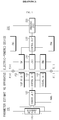
- FIG. 1 is a block diagram schematically illustrating configuration of an apparatus 100 for estimating a depth of discharging (DOD) (hereinafter, also referred to as a DOD estimating apparatus) of a secondary battery according to an exemplary embodiment of the present disclosure.
- DOD depth of discharging
- a high potential terminal and a low potential terminal (P+, P-) of the secondary battery 110 are electrically coupled with a low potential connection terminal and a high potential connection terminal (T+, T-) of an electric-powered device 200.
- the secondary battery 110 may be a lithium secondary battery, but the present disclosure is not limited by a battery type.
- the electric-powered device 200 may be a mobile computer device such as a mobile phone, a laptop computer, and a tablet computer, or a handheld multimedia device including a digital camera, a video camera, and audio/video player.
- a mobile computer device such as a mobile phone, a laptop computer, and a tablet computer
- a handheld multimedia device including a digital camera, a video camera, and audio/video player.
- the electric-powered device 200 may be an electric transport system powered by electricity such as an electric vehicle, a hybrid vehicle, an electric bike, an electric motorcycle, an electric train, an electric boat, an electric aircraft, or a power tool including a motor such as electric drill and an electric grinder.
- electricity such as an electric vehicle, a hybrid vehicle, an electric bike, an electric motorcycle, an electric train, an electric boat, an electric aircraft, or a power tool including a motor such as electric drill and an electric grinder.
- the electric-powered device 200 may be a large capacity energy storage system installed in an electrical grid to store renewable energy or excess energy of a electricity-generating plant, or an interruptible power supplier to supply power to various information and communication systems including a server computer or a mobile communication equipment in case of emergency such as blackout.
- the electric-powered device 200 includes a load 210 and/or a charging unit 220.
- the load 210 is a device that consumes electrical energy of the secondary battery 110, and as a non-limiting example, may be a rotary drive device such as a motor or a power conversion device such as a converter or an inverter.
- the charging unit 220 is a device that applies a charging current to the secondary battery 110, and as a non-limiting example, may be a charging circuit, a generator coupled to an engine of an electric drive vehicle, a regeneration charger coupled to a brake of an electric-powered vehicle, and the like.
- the charging unit 220 may apply a constant-current charge current, a pulse-type charge current, a variable charge current whose magnitude changes according to time, or the like to the secondary battery 110 under the control of the control unit 230.
- the electric-powered device 200 may include a control unit 230 to control operation of the load 210 and/or the charging unit 220.
- the control unit 230 may include a microcomputer to execute a software algorithm for controlling operation of the electric-powered device 200.
- the electric-powered device 200 may also include first through fourth switches SW1-SW4 to selectively connect the secondary battery 110 to the load 210 or the secondary battery 110 to the charging unit 220.
- the first and second switches SW1 and SW2 turns on or off an electrical connection between the secondary battery 110 and the load 210 in response to a control signal received from the control unit 230.
- the third and fourth switches SW3 and SW4 turns on or off an electrical connection between the secondary battery 110 and the charging unit 220 in response to a control signal received from the control unit 230.
- the first through fourth switches SW1-SW4 may be a semiconductor switch or a mechanical relay switch.
- the control unit 230 turns on or off an electrical connection between the secondary battery 110 and the load 210 or between the secondary battery 110 and the charging unit 220.
- the control unit 230 connects the secondary battery 110 to the load 210 by turning on the first and second switches SW1 and SW2, to operate the load 210 by electrical energy stored in the secondary battery 110. Then, the secondary battery 110 is discharged so that electrical energy is provided to the load 210.
- SOC state of charge
- control unit 230 connects the secondary battery 110 to the charging unit 220 by turning on the third and fourth switches SW3 and SW4, to apply a charging current to the secondary battery 110. Then, the charging unit 220 applies a charging current to the secondary battery 110.
- control unit 230 connects the secondary battery 110 to the load 210, and when the operation of the load 210 is temporarily stopped, may connect the secondary battery 110 to the charging unit 220 to charge the secondary battery 110.
- regeneration charging of an electric vehicle or a hybrid vehicle may be given.
- the regeneration charging refers to charging of a secondary battery using regeneration energy produced by a brake system when the vehicle slows down through brake manipulation.
- a magnitude of a charging current gradually increases from zero to a predetermined peak value and then gradually decreases to zero.
- the charging unit 220 is systemically associated with the brake system that produces regeneration energy, and the control unit 230 may control an overall regeneration charging process. Because the regeneration charging technology is widely known in the technical field to which the present disclosure belongs, its detailed description is omitted herein.
- the DOD estimating apparatus 100 includes a sensor unit 120 and a control unit 130 in order to estimate a depth of discharging (DOD) of the secondary battery 110.
- DOD depth of discharging
- the DOD is a parameter representing a relative ratio of a discharged capacity in comparison to a fully-charged capacity of the secondary battery by using a percentage or a number from 0 to 1. For example, if the DOD is 30%, this means that a capacity corresponding to 30% of the fully charged capacity of the secondary battery is discharged.
- the DOD is substantially identical to "1-SOC". Therefore, it should be understood that estimating the DOD is substantially identical to estimating a SOC.
- the sensor unit 120 includes a voltage measurement circuit, and the sensor unit 120 measures a dynamic voltage and/or a no-load voltage of the secondary battery 110 and provides the dynamic voltage and/or the no-load voltage to the control unit 130.
- the dynamic voltage means a voltage applied between a cathode and an anode of the secondary battery 110 when the secondary battery 110 is being charged or discharged.
- the no-load voltage means a voltage applied between a cathode and an anode of the secondary battery 110 when the secondary battery 110 completely stops charging and discharging or a discharge current is negligibly low.
- the sensor unit 120 may receive a measurement control signal from the control unit 130 to measure a voltage of the secondary battery 110. That is, the sensor unit 120 may measure a voltage of the secondary battery and provide the same to the control unit 130 whenever the measurement control signal is received.
- the sensor unit 120 repeatedly measures a voltage of the secondary battery 110 at time intervals and provides the measured voltage to the control unit 130 while the secondary battery 110 is being charged or discharged or the second battery 110 is in a no-load state.
- the voltage change profile of the secondary battery 110 has an increasing pattern in which an inflection point is formed.
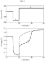
- FIG. 2 shows a voltage change profile, observed when a lithium secondary battery including a blended cathode material in which LiCo 1/3 Mn 1/3 Ni 1/3 O 2 and LiFePO 4 are blended at a ratio of 7:3 (weight ratio) is charged in a voltage region including a transition voltage range (about 3.3V to 3.4V).
- the section A represents a discharge region
- the section B represents a charge region.
- LiCo 1/3 Mn 1/3 Ni 1/3 O 2 easily reacts with working ions in a high voltage range, and LiFePO 4 easily reacts with working ions in a low voltage range. Therefore, as shown in FIG. 2 , an inflection point (see a dotted circle) is formed on the voltage change profile of the lithium secondary battery.
- the inflection point supports that the kind of cathode material reacting with working ions is changed, and thus it may be regarded that the cathode materials from which working ions are deintercalated is changed from LiFePO 4 into LiCo 1/3 Mn 1/3 Ni 1/3 O 2 near the inflection point.
- working ions are deintercalated from cathode material.
- the resistance characteristic of the secondary battery is changed, and this change of resistance characteristic is represented as an inflection point on the voltage change profile.
- the voltage change profile of the lithium secondary battery has an increasing pattern including an inflection point.
- FIG. 3 shows a voltage change profile, observed when a lithium secondary battery including a blended cathode material in which LiCo 1/3 Mn 1/3 Ni 1/3 O 2 and LiFePO 4 are blended at a ratio of 7:3 (weight ratio) as first and second cathode materials is discharged to a voltage lower than the transition voltage range (lower than 3.2V) for several seconds and then comes into a no-load state.
- the section A represents a discharge region
- the section B represents a no-load region.
- an inflection point (see a dotted circle) is formed on the voltage change profile.
- the inflection point is formed with a mechanism slightly different from the case where the secondary battery is charged.
- the capacity capable of intercalating working ions into LiCo 1/3 Mn 1/3 Ni 1/3 O 2 is mostly used, and thus the resistance of LiCo 1/3 Mn 1/3 Ni 1/3 O 2 rapidly increases. For this reason, working ions start being inserted into LiFePO 4 , instead of LiCoi 1/3 Mn 1/3 Ni 1/3 O 2 .
- the operating ions intercalated into the surfaces of LiCo 1/3 Mn 1/3 Ni 1/3 O 2 and LiFePO 4 are diffused inwards and the voltage of the secondary battery slowly increases.
- the working ions intercalated into LiFePO 4 are moved toward LiCoi 1/3 Mn 1/3 Ni 1/3 O 2 . Due to the working ion movement mechanism, the resistance characteristic of the secondary battery changes according to time, and the change of resistance characteristic results in an inflection point observed on the voltage change profile.
- the inflection point may be regarded as being created when the working ions intercalated into LiFePO 4 are mostly moved to LiCoi 1/3 Mn 1/3 Ni 1/3 O 2 .
- an inflection point is generated since the resistance characteristic of the secondary battery is changed as the kind of cathode material reacting (intercalation or deintercalation) with working ions is changed. Therefore, it may be regarded that an inflection point is observed in a voltage change profile if the kind of cathode material reacting with working ions is changed, regardless of whether the secondary battery is being charged or discharged or whether the secondary battery is in a no-load state.
- the inventors of this application have found that when an inflection point is observed in a voltage change profile of a secondary battery, as long as the DOD of the secondary battery is identical, the voltage change profile has an intrinsic pattern according to the DOD of the secondary battery after the inflection point is observed, regardless of a charge history or a discharge history of the secondary battery.
- the DOD may be simply estimated using the voltage change profile after the inflection point.
- the correlation may be a correlation between the DOD and a reference voltage measured after a predetermined time since the inflection point is created on the voltage change profile.
- at least one reference voltage may be measured.
- the correlation may be obtained by measuring a voltage change profile of the secondary battery for each DOD of the secondary battery as shown in FIGS. 2 and 3 .
- the correlation may be a correlation between the DOD and an approximation function of a voltage change profile measured for a predetermined time after the inflection point is created.
- the voltage change profile after the inflection point converges to an equilibrium voltage
- the voltage change profile may be expressed with an approximation function using extrapolation.
- the approximation function may be an exponential function of a natural logarithm (e).
- the control unit 130 receives the voltage in order to estimate a DOD of the secondary battery 110 by using the voltage change profile including an inflection point.
- the control unit 130 may generate a voltage change profile according to time by receiving the repeatedly measured voltages and identify an inflection point in the voltage change profile.
- the inflection point is identified at a location where the voltage change rate (dV/dt) for time is maximum on the voltage change profile.
- the method for identifying an inflection point is not limited thereto.
- control unit 130 may identify the inflection point in a voltage change profile measured just after the secondary battery 110 stops charging or discharging.
- control unit 130 may identify the inflection point in a voltage change profile measured while the secondary battery 110 is being charged.
- control unit 130 selects a voltage measured after the identification point of the inflection point as a reference voltage which is to be used for estimating a DOD of the secondary battery 110.
- control unit 130 selects a voltage measured after a predetermined time since the inflection point is identified as a reference voltage.
- the greater the predetermined time the better.
- the predetermined time may be 5 to 60 seconds. As another example, the predetermined time may be 20 to 40 seconds. As another example, the predetermined time may be 40 to 60 seconds.
- control unit 130 may estimate a depth of discharging (DOD) of the secondary battery from the selected reference voltage by using the predetermined correlation between the reference voltage and the DOD.
- DOD depth of discharging
- control unit 130 may estimate the DOD by using a lookup table or a lookup function in which a correlation between the reference voltage and the DOD is predefined.
- the lookup table a correlation between the reference voltage and the DOD obtained through experiments or the like is stored in a table form.
- the DOD of the secondary battery 110 may be simply estimated.
- the lookup function shows a correlation between the reference voltage and the DOD obtained through experiments or the like as a function. Since the lookup function uses the reference voltage and the DOD as an input parameter and an output parameter, respectively, if the reference voltage as an input parameter of the lookup function is put thereto, the DOD may be obtained as an output value of the lookup function. Preferably, the lookup function may be obtained by means of a numerical analysis technique.
- a temperature parameter may be further added to the lookup table and the lookup function. That is, the lookup table and the lookup function may be prepared for each temperature.
- the sensor unit 120 may further measure a temperature of the secondary battery 110 and provide the temperature of the secondary battery 110 to the control unit 130.
- the control unit 130 may identify a lookup table or lookup function corresponding to the temperature of the secondary battery 110, and may estimate a DOD of the secondary battery 110 corresponding to the reference voltage using the identified lookup table or lookup function.
- control unit 130 may estimate a DOD of the secondary battery in a different way from the above.
- the control unit 130 may determine an approximation function corresponding to a voltage change profile measured for a predetermined time after the inflection point is identified.
- the approximation function may be obtained through extrapolation and be expressed as an exponential function which converges to a specific value as time goes.
- An input parameter and an output parameter of the approximation function are respectively time and voltage.
- control unit 130 estimates a voltage after a predetermined time since the inflection point is identified as a reference voltage by using the approximation function.
- the reference voltage may be determined by putting the predetermined time as an input parameter of the approximation function.
- control unit 130 may estimate a voltage measured after 20 seconds or more, preferably 30 seconds or more, more preferably 40 seconds or more, since the inflection point is identified, as a reference voltage by using the approximation function.
- control unit 130 may estimate a DOD of the secondary battery corresponding to the reference voltage by using the lookup table or the lookup function which defines a correlation between the reference voltage and the DOD as described above.
- the temperature of the secondary battery 110 may also be additionally considered, as obvious to those skilled in the art.
- the approximation function may be expressed as an exponential function V(t) as below by means of nonlinear curve fitting.
- V t a + be ⁇ ct + d
- an input parameter and an output parameter are respectively time and voltage
- constants a, b, c and d are parameters which can be tuned by voltage data measured after the inflection point is identified. Since the function V(t) has a degree of freedom of 4, each constant may be determined by using at least four voltage data measured after the inflection point is identified.
- the approximation function may also be determined by using another nonlinear curve fitting technique which may fit a voltage change profile after the inflection point is identified.
- the approximation function may be determined by means of nonlinear regression, probability distribution fitting, polynomial curve fitting or the like.
- control unit 130 may execute a software algorithm in which at least one of the nonlinear curve fitting techniques mentioned above is programmed.
- the DOD estimating apparatus 100 of the secondary battery may further include a storage unit 160.
- the storage unit 160 is not limited to a specific type if it is a storage medium capable of recording and erasing information.
- the storage unit 160 may be random access memory (RAM), read-only memory (ROM), a register, a hard disc, an optical recording medium, or a magnetic recording medium. Also, the storage unit 160 may be connected to the control unit 130 via, for example, a data bus, to allow access by the control unit 130.
- RAM random access memory
- ROM read-only memory
- the storage unit 160 may be connected to the control unit 130 via, for example, a data bus, to allow access by the control unit 130.
- the storage unit 160 may store and/or update and/or erase and/or transmit programs including various control logics executed by the control unit 130, and/or data generated by execution of the control logics, and/or algorithms determining an approximation function by nonlinear curve fitting.
- the storage unit 160 may be logically divided into at least two, and may be included in the control unit 130.
- the storage unit 160 may store and maintain a plurality of voltages data measured by the sensor unit 120, the voltage change profile, information about the identified inflection point (time, voltage), the approximation function for a voltage change profile after the identified inflection point, the lookup table or the lookup function, the reference voltage, or the estimated DOD.
- control unit 130 may optionally include a processor, an application-specific integrated circuit (ASIC), a chipset, a logic circuit, a register, a communication modem, and a data processing device, well known in the art.
- ASIC application-specific integrated circuit
- the control unit 130 may be implemented as an assembly of program modules.
- the program module may be stored in a memory and executed by a processor.
- the memory may be disposed inside or outside a processor, and may be connected to a processor by various known means.
- the memory may be included in the storage unit 160.
- the memory generally represents all devices storing information regardless of a device type, and does not indicate a specific memory device.
- the DOD estimating apparatus 100 of the secondary battery may further include a display unit 150.
- the display unit 150 is not limited to a specific type if it can display information about the DOD of the secondary battery 110 estimated by the control unit 130 as graphical interface (a character, a number, a graph, and the like).
- the display unit 150 may be a liquid crystal display (LCD), a light-emitting diode (LED) display, an organic light-emitting diode (OLED) display, an electrophoretic ink (E-Ink) display, a flexible display, and the like.
- LCD liquid crystal display
- LED light-emitting diode
- OLED organic light-emitting diode
- E-Ink electrophoretic ink
- the display unit 150 may be connected with the control unit 130 directly or indirectly. When the latter is employed, the display unit 150 may be located in a physically separate area from an area where the control unit 130 is located. Also, a third control unit (not shown) may be interposed between the display unit 150 and the control unit 130 to receive information to be displayed on the display unit 150 from the control unit 130 and allow the information to be displayed on the display unit 150. For this, the third control unit may be connected to the control unit 130 via a communication line (for example, a CAN communication network in a vehicle).
- a communication line for example, a CAN communication network in a vehicle.
- the display unit 150 is not necessarily included in the apparatus according to the present disclosure, and may be included in other apparatus connected with the apparatus according to the present disclosure. In this case, the display unit 150 and the control unit 130 may be indirectly connected via a control unit included in other apparatus rather than being directly connected. Accordingly, it should be understood that an electrical connection of the display unit 150 and the control unit 130 includes this indirect connection method.
- the control unit 130 may form a communication interface with an external control device. Also, through the communication interface, data associated with the DOD of the secondary battery 110 may be transmitted to the external control unit.
- the external control unit may be a control unit 230 of the electric-powered device 200.
- control unit 130 may transmit data associated with the DOD of the secondary battery 110 to the control unit 230 that controls an operating mechanism of the electric vehicle in an integrated manner. Then, the control unit 230 may control the charge and discharge of the secondary battery 110 using the received DOD of the secondary battery 110, and maximize the usage efficiency of the secondary battery 110.
- a selective combination of at least one of the various control logics and/or calculation logics of the control unit 130 may become an embodiment of a method for estimating the parameter of the secondary battery.
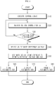
- FIG. 4 is a flowchart chronologically illustrating a method for estimating a DOD of a secondary battery according to an exemplary embodiment of the present disclosure.
- control unit 130 reads a control logic needed to estimate a DOD of a secondary battery from the storage unit 160 and executes the control logic.
- control unit 130 receives voltage data of the secondary battery 10 to obtain a voltage change profile by means of the sensor unit 120, while the secondary battery 110 is being charged or discharged, or after the secondary battery comes into a no-load state during a discharging process.
- the control unit 130 may periodically output a measurement control signal to the sensor unit 120 in order to obtain the voltage change profile.
- control unit 130 identifies an inflection point on the voltage change profile. If an inflection point is not identified, the control unit 130 proceeds to Step S20, and if an inflection point is identified, the control unit 130 proceeds to Step S40.
- the control unit 130 selects at least one voltage on a voltage change profile measured after a predetermined time after the inflection point is identified, as a reference voltage.
- the control unit 130 may obtain an approximation function by means of extrapolation by using the voltage change profile measured after the inflection point is identified, and estimate a voltage, calculated as an output value by putting the predetermined time as an input parameter of the approximation function, as a reference voltage.
- a plurality of time values may be input as an input parameter of the approximation function.
- control unit 130 estimates a DOD corresponding to the measured reference voltage or the estimated reference voltage by using a lookup table or a lookup function which defines a correlation between the reference voltage and the DOD in advance through experiments or the like.
- the flowchart of FIG. 4 may further include a step in which the control unit 130 obtains data associated with the temperature of the secondary battery 110 using the sensor unit 120, and a step of estimating a DOD by using the look-up table or the look-up function corresponding to the temperature.
- the flowchart of FIG. 4 may further include, as an optional step, at least one step among steps S60 through S80.
- control unit 130 may record the estimated DOD of the secondary battery 110 in the storage unit 160. Also, in S70, the control unit 130 may output the estimated DOD of the secondary battery 110 as graphical interface (a character, a number, a graph, and the like) through the display unit 150. Also, the control unit 130 may transmit the estimated DOD of the secondary battery 110 to the control unit 230 of the electric-powered device 200.
- control unit 130 may be selectively combined, and the combined logics may be written in a computer-readable code and recorded in a computer-readable recording medium.
- the recording medium is not limited to a specific type if it is accessible by a processor included in a computer.
- the recording medium may include at least one selected from the group consisting of ROM, RAM, a register, a compact disc read-only memory (CD-ROM), a magnetic tape, a hard disc, a floppy disc, and an optical data recording device.
- the computer-readable code may be modulated to a carrier signal and included in a communication carrier at a particular point in time, and may be distributed over network-coupled computer systems so that the computer-readable code is stored and executed in a distributed fashion.
- functional programs, codes, and code segments for implementing the combined control logics may be easily inferred by programmers in the technical field to which the present disclosure belongs.
- a secondary battery including a blended cathode material was fabricated in accordance with the following specification.
- a secondary battery including a blended cathode material comprising at least two cathode materials exhibits a unique behavior in a discharge resistance profile and an open-circuit voltage profile.
- FIGS. 5 and 6 are graphs illustrating a discharge resistance profile of the secondary battery measured for each SOC of the secondary battery and an open-circuit voltage profile measured for each DOD of the secondary battery, respectively.
- SOC stands for a state of charge
- DOD stands for a depth of discharging
- FIG. 5 it can be observed that a convex pattern in which a discharge resistance of the secondary battery locally increases and then decreases appears, and two inflection points (see dotted circles) are present before and after a peak of the convex pattern. Also, referring to FIG. 6 , an inflection point is also observed in an open-circuit voltage profile.
- the reason that the convex pattern and the inflection point are observed in the discharge resistance profile and the open-circuit voltage profile, respectively, is that resistance characteristics of the secondary battery vary with a change in type of a cathode material reacting with the working ions when the secondary battery is used in the transition voltage range.
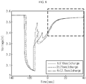
- FIG. 7 is a graph showing a voltage change profile, measured when a secondary battery is discharged in a voltage range including a transition voltage region of the secondary battery, thereafter charged for a short time period and then maintained in an idle state for a predetermined time.
- FIG. 7 three voltage change profiles measured under different experiment conditions are depicted.
- the discharge rate was identical, and the charge rate was changed into three conditions.
- the charging time was adjusted to have the same ampere counting. Therefore, even though charge rates are different depending on experiment conditions, the amount of working ions deintercalated from the cathode material when the secondary battery is charged is substantially identical. For this reason, when charging and discharging are completed, the DOD of the secondary battery is identically 71%.
- the voltage rapidly drops in a discharge region, and the voltage rapidly increases again in a charge region. A region after 30 seconds is an idle region.
- an inflection point namely a point where dV/dt becomes a maximum
- an inflection point is observed in the idle region. Therefore, it may be inferred that, when the secondary battery comes into an idle state, a potential difference is generated between two cathode materials due to the diffusion of working ions in the cathode material, and due to the potential difference, the working ions intercalated into LiFePO 4 move to LiCo 1/3 Ni 1/3 Mn 1/3 O 2 so that the resistance characteristic of the secondary battery changes.
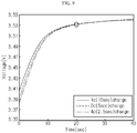
- FIG. 9 is an enlarged graph showing a dotted box portion of FIG. 8 .
- FIG. 10 is an enlarged view showing voltage change profiles, observed at the right side of the inflection point when a secondary battery is discharged and charged under the same condition as when obtaining the voltage change profiles of FIG. 7 , while changing a DOD when the idle state is initiated to 66%, 68%, 70%, 72%, 74%, 76% and 78%.
- This experiment result supports that the DOD of the secondary battery may be inherently estimated by identifying an inflection point in a voltage change profile of the secondary battery and sampling a voltage change profile at the right side of the inflection point.
- a voltage change profile designated by a dashed dotted line is sampled when the secondary battery is in an idle state, a voltage (about 3.53V, see the circle mark) measured after a predetermined time, for example 20 seconds, since the inflection point is generated may be selected as a reference voltage for estimating a DOD of the secondary battery.
- a lookup table or a lookup function defining a correlation between the reference voltage and the DOD through experiments is used, a DOD corresponding to the selected reference voltage may be simply estimated.
- the reference voltage used for determining a DOD of the secondary battery may also be estimated using an approximation function for a voltage change profile at the right side of the inflection point.
- an approximation function for example, an exponential function
- a voltage calculated as an output value when the predetermined time (for example, 20 seconds) is input as an input parameter of the approximation function may be estimated as a reference voltage.
- the DOD may be more accurately estimated by approximately estimating an entire profile form as an approximation function by using a part of the voltage change profile, estimating a voltage when the voltage change profile is sufficiently converged to an equivalent voltage by using the approximation function, and selecting this value as a reference voltage.
- FIG. 10 shows that even though different charging conditions are applied before the secondary battery comes into an idle state, as long as the DOD of the secondary battery is identical, the voltage change profiles at the right side of the inflection point converges to an equivalent voltage while forming substantially the same forms, under various DOD conditions.
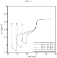
- FIG. 11 shows a voltage change profile when a secondary battery is discharged in a voltage range including a transition voltage range and then charged again.
- the cathode material from which working ions are deintercalated is changed from LiFePO 4 to LiCo 1/3 Ni 1/3 Mn 1/3 O 2 near the inflection point.
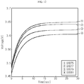
- FIG. 12 shows a voltage change profile at the right side of an inflection point when experiment conditions are set so that DOD at the termination of charging becomes 75%, 77%, 79% and 81%, respectively, and a secondary battery is discharged and charged at different discharge rates and charge rates in the same way as when the voltage change profile of FIG. 11 is obtained.
- FIG. 12 shows as if a single voltage change profile is drawn, in fact, three profiles, marked with a dotted line, a solid line and a dashed dotted line, are overlapped with each other.
- the DOD of the secondary battery may be simply estimated by using a reference voltage selected from the voltage change profile at the right side of the inflection point.
- a reference voltage a voltage measured after a predetermined time, for example 10, 20 or 30 seconds, since the inflection point is identified may be selected.
- the reference voltage may be estimated from the approximation function which is obtained from the voltage change profiles at the right side of the inflection point by means of extrapolation, as obvious to those skilled in the art.
Landscapes
- Chemical & Material Sciences (AREA)
- General Physics & Mathematics (AREA)
- Physics & Mathematics (AREA)
- General Chemical & Material Sciences (AREA)
- Chemical Kinetics & Catalysis (AREA)
- Electrochemistry (AREA)
- Composite Materials (AREA)
- Engineering & Computer Science (AREA)
- Manufacturing & Machinery (AREA)
- Secondary Cells (AREA)
- Power Engineering (AREA)
- Tests Of Electric Status Of Batteries (AREA)
- Charge And Discharge Circuits For Batteries Or The Like (AREA)
- Battery Electrode And Active Subsutance (AREA)
Priority Applications (2)
| Application Number | Priority Date | Filing Date | Title |
|---|---|---|---|
| EP20150346.3A EP3657191B1 (en) | 2012-12-04 | 2013-12-04 | Apparatus for estimating depth of discharge (dod) of secondary battery |
| PL13860399T PL2899558T3 (pl) | 2012-12-04 | 2013-12-04 | Urządzenie do szacowania głębokości rozładowania (DOD) baterii akumulatorowej |
Applications Claiming Priority (2)
| Application Number | Priority Date | Filing Date | Title |
|---|---|---|---|
| KR20120139750 | 2012-12-04 | ||
| PCT/KR2013/011176 WO2014088325A1 (ko) | 2012-12-04 | 2013-12-04 | 이차 전지의 방전 심도 추정 장치 및 방법 |
Related Child Applications (2)
| Application Number | Title | Priority Date | Filing Date |
|---|---|---|---|
| EP20150346.3A Division-Into EP3657191B1 (en) | 2012-12-04 | 2013-12-04 | Apparatus for estimating depth of discharge (dod) of secondary battery |
| EP20150346.3A Division EP3657191B1 (en) | 2012-12-04 | 2013-12-04 | Apparatus for estimating depth of discharge (dod) of secondary battery |
Publications (3)
| Publication Number | Publication Date |
|---|---|
| EP2899558A1 EP2899558A1 (en) | 2015-07-29 |
| EP2899558A4 EP2899558A4 (en) | 2016-08-03 |
| EP2899558B1 true EP2899558B1 (en) | 2020-03-25 |
Family
ID=51126077
Family Applications (2)
| Application Number | Title | Priority Date | Filing Date |
|---|---|---|---|
| EP13860399.8A Active EP2899558B1 (en) | 2012-12-04 | 2013-12-04 | Apparatus for estimating depth of discharge (dod) of secondary battery |
| EP20150346.3A Active EP3657191B1 (en) | 2012-12-04 | 2013-12-04 | Apparatus for estimating depth of discharge (dod) of secondary battery |
Family Applications After (1)
| Application Number | Title | Priority Date | Filing Date |
|---|---|---|---|
| EP20150346.3A Active EP3657191B1 (en) | 2012-12-04 | 2013-12-04 | Apparatus for estimating depth of discharge (dod) of secondary battery |
Country Status (7)
| Country | Link |
|---|---|
| US (1) | US9678165B2 (ja) |
| EP (2) | EP2899558B1 (ja) |
| JP (1) | JP6185597B2 (ja) |
| KR (1) | KR101454832B1 (ja) |
| CN (1) | CN104871021B (ja) |
| PL (2) | PL3657191T3 (ja) |
| WO (1) | WO2014088325A1 (ja) |
Families Citing this family (19)
| Publication number | Priority date | Publication date | Assignee | Title |
|---|---|---|---|---|
| JP6044512B2 (ja) * | 2013-11-07 | 2016-12-14 | 株式会社デンソー | 電池特性学習装置 |
| KR101798201B1 (ko) * | 2014-10-01 | 2017-11-15 | 주식회사 엘지화학 | 이차 전지의 방전 출력 추정 방법 및 장치 |
| US10354026B2 (en) * | 2016-02-16 | 2019-07-16 | Dassault Systemes Simulia Corp. | System and method for the generation and use of an electro-thermal battery model |
| KR102547376B1 (ko) * | 2016-03-03 | 2023-06-26 | 삼성전자주식회사 | 전자 장치, 충전 제어 방법 및 컴퓨터 판독가능 기록매체 |
| KR102155333B1 (ko) * | 2017-07-06 | 2020-09-11 | 주식회사 엘지화학 | 이차 전지의 용량유지율을 추정하는 장치 및 방법 |
| JP2019040845A (ja) * | 2017-08-29 | 2019-03-14 | Toyo Tire株式会社 | 二次電池の状態予測方法、充電制御方法、システム、及びプログラム |
| KR102515606B1 (ko) * | 2017-10-31 | 2023-03-28 | 삼성에스디아이 주식회사 | 배터리 충전량 표시 방법 및 이를 수행하는 배터리 팩 및 전자 기기 |
| FR3076908B1 (fr) * | 2018-01-16 | 2021-01-01 | Renault Sas | Procede de detection d'une cellule defaillante dans une batterie electrique |
| KR102343422B1 (ko) | 2018-04-10 | 2021-12-24 | 주식회사 엘지에너지솔루션 | 배터리 진단 장치 및 방법 |
| KR102362886B1 (ko) * | 2018-04-10 | 2022-02-14 | 주식회사 엘지에너지솔루션 | 배터리 진단 장치 및 방법 |
| KR102258821B1 (ko) | 2018-04-30 | 2021-05-31 | 주식회사 엘지에너지솔루션 | 이차 전지 테스트 장치 및 방법 |
| CN110907056A (zh) * | 2018-09-14 | 2020-03-24 | 宁德时代新能源科技股份有限公司 | 一种电池组温度检测系统 |
| CN109143082A (zh) * | 2018-10-30 | 2019-01-04 | 双登集团股份有限公司 | 铅酸蓄电池最佳放电深度测试分析与评估方法 |
| CN110988702B (zh) | 2019-04-25 | 2021-04-02 | 宁德时代新能源科技股份有限公司 | 电池可用容量确定方法、装置、管理系统以及存储介质 |
| KR20210016795A (ko) * | 2019-08-05 | 2021-02-17 | 주식회사 엘지화학 | 에너지 허브 장치 및 에너지 관리 방법 |
| KR20210141219A (ko) * | 2020-05-15 | 2021-11-23 | 주식회사 엘지에너지솔루션 | 충전 심도 설정 장치 및 방법 |
| CN112305429B (zh) * | 2020-09-28 | 2022-08-09 | 合肥国轩高科动力能源有限公司 | 一种锂离子电池放电深度的估算方法 |
| JP2023131650A (ja) * | 2022-03-09 | 2023-09-22 | 株式会社日立製作所 | 状態診断装置および状態診断システム |
| CN116929437B (zh) * | 2023-09-15 | 2023-12-08 | 深圳和润达科技有限公司 | 应用于电芯化成分容系统的传感器信息识别方法及装置 |
Family Cites Families (24)
| Publication number | Priority date | Publication date | Assignee | Title |
|---|---|---|---|---|
| JPH06342044A (ja) | 1993-05-31 | 1994-12-13 | Omron Corp | バッテリー計測装置 |
| JPH08331769A (ja) * | 1995-05-31 | 1996-12-13 | Honda Motor Co Ltd | 2次電池の充電制御方法およびその装置 |
| JP3740323B2 (ja) | 1998-07-31 | 2006-02-01 | キヤノン株式会社 | 二次電池の充電方法及びその装置 |
| WO2000062086A1 (en) | 1999-04-08 | 2000-10-19 | Koninklijke Philips Electronics N.V. | Method of and device for determining the charge condition of a battery |
| JP2001185095A (ja) * | 1999-12-22 | 2001-07-06 | Sony Corp | 二次電池 |
| US6677082B2 (en) | 2000-06-22 | 2004-01-13 | The University Of Chicago | Lithium metal oxide electrodes for lithium cells and batteries |
| US6680143B2 (en) | 2000-06-22 | 2004-01-20 | The University Of Chicago | Lithium metal oxide electrodes for lithium cells and batteries |
| JP2002250757A (ja) | 2001-02-23 | 2002-09-06 | Yazaki Corp | 車両用バッテリの開回路電圧推定方法及びその装置 |
| KR20030013215A (ko) | 2001-08-07 | 2003-02-14 | 주식회사 맥사이언스 | 과도 응답 함수를 이용한 축전지의 용량 예측 및 선별 방법 |
| GB0312303D0 (en) * | 2003-05-29 | 2003-07-02 | Yuasa Battery Uk Ltd | Battery life monitor and battery state of charge monitor |
| US7482784B2 (en) * | 2003-07-15 | 2009-01-27 | Panasonic Corporation | Degradation judgment circuit for secondary battery |
| JP2006304516A (ja) | 2005-04-21 | 2006-11-02 | Nissan Motor Co Ltd | バッテリ充電制御装置及びバッテリ充電制御方法 |
| JP5092224B2 (ja) * | 2005-10-05 | 2012-12-05 | パナソニック株式会社 | 非水電解液二次電池とその電池パックおよび電子機器 |
| JP2007250299A (ja) * | 2006-03-15 | 2007-09-27 | Hitachi Vehicle Energy Ltd | 非水電解液二次電池 |
| US7928735B2 (en) * | 2007-07-23 | 2011-04-19 | Yung-Sheng Huang | Battery performance monitor |
| KR20110008101A (ko) * | 2008-12-05 | 2011-01-25 | 파나소닉 주식회사 | 전지 팩 |
| WO2011007805A1 (ja) * | 2009-07-17 | 2011-01-20 | 本田技研工業株式会社 | リチウムイオン二次電池監視システム及びリチウムイオン二次電池監視方法 |
| JP5638779B2 (ja) | 2009-08-24 | 2014-12-10 | 三洋電機株式会社 | 二次電池の特性検出方法および二次電池装置 |
| KR101750739B1 (ko) | 2010-01-19 | 2017-06-27 | 가부시키가이샤 지에스 유아사 | 2차 전지의 충전 상태 측정 장치 및 2차 전지의 충전 상태 측정 방법 |
| KR20120139750A (ko) | 2010-02-23 | 2012-12-27 | 도레이 카부시키가이샤 | 프리폼 및 그의 제조 방법 |
| JP5282789B2 (ja) * | 2011-01-11 | 2013-09-04 | 株式会社デンソー | リチウムイオン二次電池の電池容量検出装置 |
| KR101097956B1 (ko) | 2011-01-21 | 2011-12-22 | 동국대학교 산학협력단 | 충전 상태 산출 장치 및 방법 |
| EP2838151B1 (en) * | 2012-04-13 | 2017-08-23 | LG Chem, Ltd. | System of secondary cell including mixed cathode material, and apparatus and method for secondary cell management |
| CN102645636B (zh) * | 2012-04-19 | 2014-05-07 | 北京优科利尔能源设备有限公司 | 一种电池容量检测方法 |
-
2013
- 2013-12-04 WO PCT/KR2013/011176 patent/WO2014088325A1/ko active Application Filing
- 2013-12-04 PL PL20150346.3T patent/PL3657191T3/pl unknown
- 2013-12-04 JP JP2015546384A patent/JP6185597B2/ja active Active
- 2013-12-04 PL PL13860399T patent/PL2899558T3/pl unknown
- 2013-12-04 EP EP13860399.8A patent/EP2899558B1/en active Active
- 2013-12-04 KR KR1020130149795A patent/KR101454832B1/ko active IP Right Grant
- 2013-12-04 CN CN201380055143.6A patent/CN104871021B/zh active Active
- 2013-12-04 US US14/424,622 patent/US9678165B2/en active Active
- 2013-12-04 EP EP20150346.3A patent/EP3657191B1/en active Active
Non-Patent Citations (1)
| Title |
|---|
| None * |
Also Published As
| Publication number | Publication date |
|---|---|
| KR101454832B1 (ko) | 2014-10-28 |
| EP2899558A1 (en) | 2015-07-29 |
| JP6185597B2 (ja) | 2017-08-23 |
| US9678165B2 (en) | 2017-06-13 |
| PL3657191T3 (pl) | 2023-01-30 |
| JP2016508215A (ja) | 2016-03-17 |
| EP2899558A4 (en) | 2016-08-03 |
| KR20140071936A (ko) | 2014-06-12 |
| CN104871021A (zh) | 2015-08-26 |
| EP3657191A1 (en) | 2020-05-27 |
| CN104871021B (zh) | 2017-05-31 |
| PL2899558T3 (pl) | 2020-07-13 |
| US20150226809A1 (en) | 2015-08-13 |
| EP3657191B1 (en) | 2022-11-09 |
| WO2014088325A1 (ko) | 2014-06-12 |
Similar Documents
| Publication | Publication Date | Title |
|---|---|---|
| EP2899558B1 (en) | Apparatus for estimating depth of discharge (dod) of secondary battery | |
| EP2899795B1 (en) | Apparatus and method for estimating output of secondary battery including blended anode material | |
| US9720047B2 (en) | Apparatus and method for estimating parameter of secondary battery | |
| US9389278B2 (en) | Apparatus and method for estimating power of secondary blended comprising blended cathode material | |
| US9897660B2 (en) | Apparatus and method for estimating parameter of secondary battery | |
| EP3901642B1 (en) | Apparatus and method for estimating soc of secondary battery including blended cathode material | |
| US20150066407A1 (en) | Apparatus and method for estimating parameter of secondary battery | |
| Rahimi-Eichi et al. | Batteries |
Legal Events
| Date | Code | Title | Description |
|---|---|---|---|
| PUAI | Public reference made under article 153(3) epc to a published international application that has entered the european phase |
Free format text: ORIGINAL CODE: 0009012 |
|
| 17P | Request for examination filed |
Effective date: 20150422 |
|
| AK | Designated contracting states |
Kind code of ref document: A1 Designated state(s): AL AT BE BG CH CY CZ DE DK EE ES FI FR GB GR HR HU IE IS IT LI LT LU LV MC MK MT NL NO PL PT RO RS SE SI SK SM TR |
|
| AX | Request for extension of the european patent |
Extension state: BA ME |
|
| DAX | Request for extension of the european patent (deleted) | ||
| RA4 | Supplementary search report drawn up and despatched (corrected) |
Effective date: 20160630 |
|
| RIC1 | Information provided on ipc code assigned before grant |
Ipc: H01M 4/58 20060101ALI20160624BHEP Ipc: H01M 4/525 20100101ALI20160624BHEP Ipc: H01M 4/505 20100101ALI20160624BHEP Ipc: H01M 4/36 20060101ALI20160624BHEP Ipc: G01R 19/165 20060101ALI20160624BHEP Ipc: H01M 10/052 20100101ALI20160624BHEP Ipc: G01R 31/36 20060101AFI20160624BHEP Ipc: H01M 10/48 20060101ALI20160624BHEP Ipc: H01M 4/131 20100101ALI20160624BHEP |
|
| STAA | Information on the status of an ep patent application or granted ep patent |
Free format text: STATUS: EXAMINATION IS IN PROGRESS |
|
| 17Q | First examination report despatched |
Effective date: 20181025 |
|
| GRAP | Despatch of communication of intention to grant a patent |
Free format text: ORIGINAL CODE: EPIDOSNIGR1 |
|
| STAA | Information on the status of an ep patent application or granted ep patent |
Free format text: STATUS: GRANT OF PATENT IS INTENDED |
|
| INTG | Intention to grant announced |
Effective date: 20190924 |
|
| GRAS | Grant fee paid |
Free format text: ORIGINAL CODE: EPIDOSNIGR3 |
|
| GRAA | (expected) grant |
Free format text: ORIGINAL CODE: 0009210 |
|
| STAA | Information on the status of an ep patent application or granted ep patent |
Free format text: STATUS: THE PATENT HAS BEEN GRANTED |
|
| RAP1 | Party data changed (applicant data changed or rights of an application transferred) |
Owner name: LG CHEM, LTD. |
|
| AK | Designated contracting states |
Kind code of ref document: B1 Designated state(s): AL AT BE BG CH CY CZ DE DK EE ES FI FR GB GR HR HU IE IS IT LI LT LU LV MC MK MT NL NO PL PT RO RS SE SI SK SM TR |
|
| REG | Reference to a national code |
Ref country code: GB Ref legal event code: FG4D |
|
| REG | Reference to a national code |
Ref country code: DE Ref legal event code: R096 Ref document number: 602013067284 Country of ref document: DE |
|
| REG | Reference to a national code |
Ref country code: AT Ref legal event code: REF Ref document number: 1249165 Country of ref document: AT Kind code of ref document: T Effective date: 20200415 Ref country code: IE Ref legal event code: FG4D |
|
| PG25 | Lapsed in a contracting state [announced via postgrant information from national office to epo] |
Ref country code: NO Free format text: LAPSE BECAUSE OF FAILURE TO SUBMIT A TRANSLATION OF THE DESCRIPTION OR TO PAY THE FEE WITHIN THE PRESCRIBED TIME-LIMIT Effective date: 20200625 Ref country code: RS Free format text: LAPSE BECAUSE OF FAILURE TO SUBMIT A TRANSLATION OF THE DESCRIPTION OR TO PAY THE FEE WITHIN THE PRESCRIBED TIME-LIMIT Effective date: 20200325 Ref country code: FI Free format text: LAPSE BECAUSE OF FAILURE TO SUBMIT A TRANSLATION OF THE DESCRIPTION OR TO PAY THE FEE WITHIN THE PRESCRIBED TIME-LIMIT Effective date: 20200325 |
|
| PG25 | Lapsed in a contracting state [announced via postgrant information from national office to epo] |
Ref country code: HR Free format text: LAPSE BECAUSE OF FAILURE TO SUBMIT A TRANSLATION OF THE DESCRIPTION OR TO PAY THE FEE WITHIN THE PRESCRIBED TIME-LIMIT Effective date: 20200325 Ref country code: GR Free format text: LAPSE BECAUSE OF FAILURE TO SUBMIT A TRANSLATION OF THE DESCRIPTION OR TO PAY THE FEE WITHIN THE PRESCRIBED TIME-LIMIT Effective date: 20200626 Ref country code: SE Free format text: LAPSE BECAUSE OF FAILURE TO SUBMIT A TRANSLATION OF THE DESCRIPTION OR TO PAY THE FEE WITHIN THE PRESCRIBED TIME-LIMIT Effective date: 20200325 Ref country code: LV Free format text: LAPSE BECAUSE OF FAILURE TO SUBMIT A TRANSLATION OF THE DESCRIPTION OR TO PAY THE FEE WITHIN THE PRESCRIBED TIME-LIMIT Effective date: 20200325 Ref country code: BG Free format text: LAPSE BECAUSE OF FAILURE TO SUBMIT A TRANSLATION OF THE DESCRIPTION OR TO PAY THE FEE WITHIN THE PRESCRIBED TIME-LIMIT Effective date: 20200625 |
|
| REG | Reference to a national code |
Ref country code: NL Ref legal event code: MP Effective date: 20200325 |
|
| REG | Reference to a national code |
Ref country code: LT Ref legal event code: MG4D |
|
| PG25 | Lapsed in a contracting state [announced via postgrant information from national office to epo] |
Ref country code: NL Free format text: LAPSE BECAUSE OF FAILURE TO SUBMIT A TRANSLATION OF THE DESCRIPTION OR TO PAY THE FEE WITHIN THE PRESCRIBED TIME-LIMIT Effective date: 20200325 |
|
| PG25 | Lapsed in a contracting state [announced via postgrant information from national office to epo] |
Ref country code: CZ Free format text: LAPSE BECAUSE OF FAILURE TO SUBMIT A TRANSLATION OF THE DESCRIPTION OR TO PAY THE FEE WITHIN THE PRESCRIBED TIME-LIMIT Effective date: 20200325 Ref country code: LT Free format text: LAPSE BECAUSE OF FAILURE TO SUBMIT A TRANSLATION OF THE DESCRIPTION OR TO PAY THE FEE WITHIN THE PRESCRIBED TIME-LIMIT Effective date: 20200325 Ref country code: EE Free format text: LAPSE BECAUSE OF FAILURE TO SUBMIT A TRANSLATION OF THE DESCRIPTION OR TO PAY THE FEE WITHIN THE PRESCRIBED TIME-LIMIT Effective date: 20200325 Ref country code: SM Free format text: LAPSE BECAUSE OF FAILURE TO SUBMIT A TRANSLATION OF THE DESCRIPTION OR TO PAY THE FEE WITHIN THE PRESCRIBED TIME-LIMIT Effective date: 20200325 Ref country code: SK Free format text: LAPSE BECAUSE OF FAILURE TO SUBMIT A TRANSLATION OF THE DESCRIPTION OR TO PAY THE FEE WITHIN THE PRESCRIBED TIME-LIMIT Effective date: 20200325 Ref country code: RO Free format text: LAPSE BECAUSE OF FAILURE TO SUBMIT A TRANSLATION OF THE DESCRIPTION OR TO PAY THE FEE WITHIN THE PRESCRIBED TIME-LIMIT Effective date: 20200325 Ref country code: IS Free format text: LAPSE BECAUSE OF FAILURE TO SUBMIT A TRANSLATION OF THE DESCRIPTION OR TO PAY THE FEE WITHIN THE PRESCRIBED TIME-LIMIT Effective date: 20200725 Ref country code: PT Free format text: LAPSE BECAUSE OF FAILURE TO SUBMIT A TRANSLATION OF THE DESCRIPTION OR TO PAY THE FEE WITHIN THE PRESCRIBED TIME-LIMIT Effective date: 20200818 |
|
| REG | Reference to a national code |
Ref country code: AT Ref legal event code: MK05 Ref document number: 1249165 Country of ref document: AT Kind code of ref document: T Effective date: 20200325 |
|
| REG | Reference to a national code |
Ref country code: DE Ref legal event code: R097 Ref document number: 602013067284 Country of ref document: DE |
|
| PG25 | Lapsed in a contracting state [announced via postgrant information from national office to epo] |
Ref country code: ES Free format text: LAPSE BECAUSE OF FAILURE TO SUBMIT A TRANSLATION OF THE DESCRIPTION OR TO PAY THE FEE WITHIN THE PRESCRIBED TIME-LIMIT Effective date: 20200325 Ref country code: AT Free format text: LAPSE BECAUSE OF FAILURE TO SUBMIT A TRANSLATION OF THE DESCRIPTION OR TO PAY THE FEE WITHIN THE PRESCRIBED TIME-LIMIT Effective date: 20200325 Ref country code: DK Free format text: LAPSE BECAUSE OF FAILURE TO SUBMIT A TRANSLATION OF THE DESCRIPTION OR TO PAY THE FEE WITHIN THE PRESCRIBED TIME-LIMIT Effective date: 20200325 Ref country code: IT Free format text: LAPSE BECAUSE OF FAILURE TO SUBMIT A TRANSLATION OF THE DESCRIPTION OR TO PAY THE FEE WITHIN THE PRESCRIBED TIME-LIMIT Effective date: 20200325 |
|
| PLBE | No opposition filed within time limit |
Free format text: ORIGINAL CODE: 0009261 |
|
| STAA | Information on the status of an ep patent application or granted ep patent |
Free format text: STATUS: NO OPPOSITION FILED WITHIN TIME LIMIT |
|
| 26N | No opposition filed |
Effective date: 20210112 |
|
| PG25 | Lapsed in a contracting state [announced via postgrant information from national office to epo] |
Ref country code: SI Free format text: LAPSE BECAUSE OF FAILURE TO SUBMIT A TRANSLATION OF THE DESCRIPTION OR TO PAY THE FEE WITHIN THE PRESCRIBED TIME-LIMIT Effective date: 20200325 |
|
| REG | Reference to a national code |
Ref country code: CH Ref legal event code: PL |
|
| PG25 | Lapsed in a contracting state [announced via postgrant information from national office to epo] |
Ref country code: MC Free format text: LAPSE BECAUSE OF FAILURE TO SUBMIT A TRANSLATION OF THE DESCRIPTION OR TO PAY THE FEE WITHIN THE PRESCRIBED TIME-LIMIT Effective date: 20200325 |
|
| REG | Reference to a national code |
Ref country code: BE Ref legal event code: MM Effective date: 20201231 |
|
| PG25 | Lapsed in a contracting state [announced via postgrant information from national office to epo] |
Ref country code: IE Free format text: LAPSE BECAUSE OF NON-PAYMENT OF DUE FEES Effective date: 20201204 Ref country code: LU Free format text: LAPSE BECAUSE OF NON-PAYMENT OF DUE FEES Effective date: 20201204 |
|
| PG25 | Lapsed in a contracting state [announced via postgrant information from national office to epo] |
Ref country code: LI Free format text: LAPSE BECAUSE OF NON-PAYMENT OF DUE FEES Effective date: 20201231 Ref country code: CH Free format text: LAPSE BECAUSE OF NON-PAYMENT OF DUE FEES Effective date: 20201231 |
|
| PG25 | Lapsed in a contracting state [announced via postgrant information from national office to epo] |
Ref country code: TR Free format text: LAPSE BECAUSE OF FAILURE TO SUBMIT A TRANSLATION OF THE DESCRIPTION OR TO PAY THE FEE WITHIN THE PRESCRIBED TIME-LIMIT Effective date: 20200325 Ref country code: MT Free format text: LAPSE BECAUSE OF FAILURE TO SUBMIT A TRANSLATION OF THE DESCRIPTION OR TO PAY THE FEE WITHIN THE PRESCRIBED TIME-LIMIT Effective date: 20200325 Ref country code: CY Free format text: LAPSE BECAUSE OF FAILURE TO SUBMIT A TRANSLATION OF THE DESCRIPTION OR TO PAY THE FEE WITHIN THE PRESCRIBED TIME-LIMIT Effective date: 20200325 |
|
| PG25 | Lapsed in a contracting state [announced via postgrant information from national office to epo] |
Ref country code: MK Free format text: LAPSE BECAUSE OF FAILURE TO SUBMIT A TRANSLATION OF THE DESCRIPTION OR TO PAY THE FEE WITHIN THE PRESCRIBED TIME-LIMIT Effective date: 20200325 Ref country code: AL Free format text: LAPSE BECAUSE OF FAILURE TO SUBMIT A TRANSLATION OF THE DESCRIPTION OR TO PAY THE FEE WITHIN THE PRESCRIBED TIME-LIMIT Effective date: 20200325 |
|
| PG25 | Lapsed in a contracting state [announced via postgrant information from national office to epo] |
Ref country code: BE Free format text: LAPSE BECAUSE OF NON-PAYMENT OF DUE FEES Effective date: 20201231 |
|
| REG | Reference to a national code |
Ref country code: DE Ref legal event code: R081 Ref document number: 602013067284 Country of ref document: DE Owner name: LG ENERGY SOLUTION, LTD., KR Free format text: FORMER OWNER: LG CHEM, LTD., SEOUL, KR |
|
| P01 | Opt-out of the competence of the unified patent court (upc) registered |
Effective date: 20230512 |
|
| REG | Reference to a national code |
Ref country code: GB Ref legal event code: 732E Free format text: REGISTERED BETWEEN 20230824 AND 20230831 |
|
| PGFP | Annual fee paid to national office [announced via postgrant information from national office to epo] |
Ref country code: GB Payment date: 20231120 Year of fee payment: 11 |
|
| PGFP | Annual fee paid to national office [announced via postgrant information from national office to epo] |
Ref country code: FR Payment date: 20231121 Year of fee payment: 11 Ref country code: DE Payment date: 20231120 Year of fee payment: 11 |
|
| PGFP | Annual fee paid to national office [announced via postgrant information from national office to epo] |
Ref country code: PL Payment date: 20231122 Year of fee payment: 11 |