EP2898513B1 - Vorrichtung zum verschliessen eines antriebsgehäuserohrs - Google Patents
Vorrichtung zum verschliessen eines antriebsgehäuserohrs Download PDFInfo
- Publication number
- EP2898513B1 EP2898513B1 EP13753827.8A EP13753827A EP2898513B1 EP 2898513 B1 EP2898513 B1 EP 2898513B1 EP 13753827 A EP13753827 A EP 13753827A EP 2898513 B1 EP2898513 B1 EP 2898513B1
- Authority
- EP
- European Patent Office
- Prior art keywords
- plug
- sealing
- tube
- housing
- plug housing
- Prior art date
- Legal status (The legal status is an assumption and is not a legal conclusion. Google has not performed a legal analysis and makes no representation as to the accuracy of the status listed.)
- Active
Links
Images


Classifications
-
- G—PHYSICS
- G21—NUCLEAR PHYSICS; NUCLEAR ENGINEERING
- G21C—NUCLEAR REACTORS
- G21C13/00—Pressure vessels; Containment vessels; Containment in general
- G21C13/02—Details
- G21C13/06—Sealing-plugs
- G21C13/067—Sealing-plugs for tubes, e.g. standpipes; Locking devices for plugs
- G21C13/0675—Seals for the plugs
-
- G—PHYSICS
- G21—NUCLEAR PHYSICS; NUCLEAR ENGINEERING
- G21C—NUCLEAR REACTORS
- G21C7/00—Control of nuclear reaction
- G21C7/06—Control of nuclear reaction by application of neutron-absorbing material, i.e. material with absorption cross-section very much in excess of reflection cross-section
- G21C7/08—Control of nuclear reaction by application of neutron-absorbing material, i.e. material with absorption cross-section very much in excess of reflection cross-section by displacement of solid control elements, e.g. control rods
- G21C7/12—Means for moving control elements to desired position
-
- G—PHYSICS
- G21—NUCLEAR PHYSICS; NUCLEAR ENGINEERING
- G21C—NUCLEAR REACTORS
- G21C13/00—Pressure vessels; Containment vessels; Containment in general
- G21C13/02—Details
- G21C13/06—Sealing-plugs
- G21C13/067—Sealing-plugs for tubes, e.g. standpipes; Locking devices for plugs
-
- Y—GENERAL TAGGING OF NEW TECHNOLOGICAL DEVELOPMENTS; GENERAL TAGGING OF CROSS-SECTIONAL TECHNOLOGIES SPANNING OVER SEVERAL SECTIONS OF THE IPC; TECHNICAL SUBJECTS COVERED BY FORMER USPC CROSS-REFERENCE ART COLLECTIONS [XRACs] AND DIGESTS
- Y02—TECHNOLOGIES OR APPLICATIONS FOR MITIGATION OR ADAPTATION AGAINST CLIMATE CHANGE
- Y02E—REDUCTION OF GREENHOUSE GAS [GHG] EMISSIONS, RELATED TO ENERGY GENERATION, TRANSMISSION OR DISTRIBUTION
- Y02E30/00—Energy generation of nuclear origin
- Y02E30/30—Nuclear fission reactors
Definitions
- the invention relates to a device for closing a drive housing tube.
- This comprises a closure plug, which serves to close an upwardly opening pipe opening of the control rod drive of a boiling water reactor receiving tube, the drive housing tube.
- Control rods serve to control the chain reactions taking place in the fuel assemblies of the reactor pressure vessel, absorbing more or fewer neutrons which are released in the chain reaction, depending on how far they have entered the reactor pressure vessel.
- control rods are retracted from below in the reactor core comprising a plurality of fuel elements.
- the required for retraction of the control rods motors are located in a space below the reactor pressure vessel, wherein in a known manner, an approximately rod-shaped control rod carrier in the drive housing tube, which is passed with its upper end through the bottom of the reactor pressure vessel, vertically movable.
- the drive technology in question here is known, so that it is possible to dispense with more detailed information on this.
- the drive housing tube is open at the top, ie it opens with a pipe opening in the interior of the reactor pressure vessel. In order to prevent leakage of primary coolant in the event of disassembly or repair of the drive systems located below the reactor pressure vessel, a closure of said pipe opening is required.
- the object of the invention is to propose a device with which a drive housing tube sealed in a simple and reliable way and the seal can be reversed again.
- the device comprises a closure stopper with a stopper housing open at the bottom and a sealing element guided axially movably within the stopper housing.
- the sealing element has a sealing surface for sealing engagement with an annular sealing surface which surrounds the upper tube opening of the drive housing tube.
- the device comprises a locking element, which serves for fixing the plug housing to the drive housing tube.
- a spring which is supported with its upper end on the plug housing and with its lower end on the sealing element while holding this in a lower end position or acted upon in the direction of this end position with a spring force.
- Such a configuration makes it possible for the closure stopper to be placed on the upper tube end of the drive housing tube with a feed movement directed vertically downwards, and the stopper housing can be fixed on the tube end. Due to the resilient mounting of the sealing element can the plug housing, after the sealing element rests with its sealing surface against a mating surface of the drive housing tube in the sense of a sealing mating, are further moved vertically down until the sealing element is pressed with a predetermined force to the mating surface. Then, the locking element can be activated and the sealing plug can be axially fixed to the drive housing tube.
- the locking element is designed such that it is rotatably mounted with respect to the central longitudinal axis of the sealing plug on the plug housing and between a locking position in which it is axially effectively fixed to the pipe end and a release position in which the Axialfix ist is repealed.
- the rotatable mounting of the locking element makes it possible to perform a reliable locking of the sealing plug in its end position or mounting position, even from a great distance.
- the lock can be canceled by turning back the locking element in its release position, the fixation of the sealing plug, so that it can be removed again from the drive housing tube.
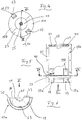
- a device of the type according to the invention which, in addition to a sealing plug, also comprises a tool serving to handle it, serves to close a drive housing tube 1, which, as in FIG Fig. 1 shown schematically, an opening 2 in the bottom 3 of a reactor pressure vessel 4 passes through.
- the drive housing tube 1 stands with its upper end portion 5 into the interior 6 of the reactor pressure vessel. With the device in question, the upper tube opening 7 of the drive housing tube 1 is closed.
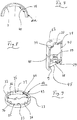
- the purpose serving sealing plug 8, which in Fig. 2 to Fig. 10 is shown, comprises a downwardly open, so a bottom opening 9 having plug housing 10, an axially movably guided inside the plug housing 10 sealing element 13 and a locking element 14.
- the sealing element 13 has a sealing surface 15 which is designed so that it sealing on a mating surface 16 of the pipe end 5, which bounds the pipe opening 7, may rest.
- the mating surface 7 is, for example, an upwardly expanding conical surface.
- the sealing surface 15 is formed as a downwardly tapering conical surface.
- the sealing element 13 is with respect to the central longitudinal axis 17 of the Sealing plug 8 movably mounted on the plug housing 10 and aligned coaxially to the central longitudinal axis 17.
- guide pin 19 is arranged at the top of the formed approximately as a truncated cone sealing element 13 at the top of the formed approximately as a truncated cone sealing element 13 at the top of the formed approximately as a truncated cone sealing element 13 at the top of the formed approximately as a truncated cone sealing element 13 at the top of the formed approximately as a truncated cone sealing element 13 at the top of the formed approximately as a truncated cone sealing element 13 is an upwardly away extending, coaxially aligned with the central longitudinal axis 17 guide pin 19 is arranged. Its upper end is guided through an opening 20 in an upper, transversely to the central longitudinal axis 17 extending wall 23 with axial mobility.
- the upper end face of the guide pin 19 is connected to a head 24 which is wider in relation to its diameter and bears against the upper side of the wall 23 of the stopper housing 10, for example by means of a screw 25.
- a trained example as a helical compression spring spring 26 is arranged, which surrounds the guide pin coaxial and is supported with its upper end on the plug housing 10, namely on the wall 23, and with its lower end on the upper side of the sealing element 13.
- the sealing element is biased in this manner in a lower end position ( Figure 3 ).
- the sealing element 13, which has a circular cross-sectional shape, is dimensioned in the radial direction or in a direction extending transversely to the central longitudinal axis 17 so that between it and the inner wall of the plug housing 10, an annular gap 27 is present.
- the sealing element 13 further has a downwardly opening central cavity 28.
- the plug housing 10 has a cylindrical side wall 29, which is bounded by the side wall 29 Interior transverse to the central longitudinal axis 17 is dimensioned such that the plug housing 10 on the upper pipe section 5 and on the adjoining the pipe opening 7 downwardly pipe section 30 of the drive housing tube 1 can be plugged without obstruction.
- the locking element 14 further has at least one radially inwardly projecting and upwardly facing stop surface 33, which serves for engaging behind a downwardly facing counter surface 34 at the upper end portion 5 and the pipe section 30. More specifically, the locking element 14 is a ring with a total of four, each pairwise diametrically opposite stop surfaces 33, which form part of the top of radially inwardly projecting ring segments 35. Between two circumferentially adjacent ring segments 35 each have a recess 36 is present.
- the annular locking element 14 is located in an existing in the inner wall of the plug housing 10 annular groove 37 a.
- recesses 38 are present in the inner wall of the plug housing 10 also extending in the axial direction or in the direction of the central longitudinal axis 17 recesses 38 are present.
- the recesses 38 extend with portions 39a, 39b upwards or downwards from the Ring groove 37 away.
- the width 40 of the recesses 39 corresponds to the width 43 of the recesses 36 present on the locking element 14.
- the mutually facing inner sides of the ring segments 35 extend on a cylindrical surface (not shown in the figures) whose diameter 44 corresponds to the diameter 45 of the inner wall of the stopper housing 10, the latter is measured in a wall region of the side wall 29 of the stopper housing which adjoins the annular groove 37 immediately upwards and downwards.
- the locking element 14 is rotatably held in the annular groove 37.
- a first rotational position which corresponds to the above-mentioned release position
- the recesses 36 are congruent with the recesses 38 of the plug housing.
- the locking position ( Fig. 3 )
- the locking element 14 relative to the plug housing 10 is rotated so that the ring segments 35 are arranged in the region of the recesses 38 of the plug housing 10.
- the ring segments 35 engage and respectively overlap the stop faces 33 on the drive housing tube 1 with their stop faces 33 facing upwards.
- the counter faces 34 are the lower end faces of ribs 46 extending in the direction of the central longitudinal axis 17, which are radially on the outer circumference of the tube section 30 protrude outwardly and are circumferentially spaced according to the recesses 36 of the locking element 14.
- the length 47 of the ribs 46 corresponds to the length 48 of the upwardly extending away from the annular groove 37 areas 39b of the recesses 38 of the plug housing 10.
- the ribs 46 are completely within the upper portions 39b of the recesses 38, thus do not protrude into the annular groove 37, so that the locking element with its radially inwardly projecting ring segments 35 under the mating surfaces 34th the ribs 46 can be moved.
- At least one rotary actuating element 50 protruding with a projection 49 from the outer circumference of the plug housing 10 is present.
- two rotary actuating elements 50 are provided, which are arranged at diametrically opposite points on the outside of the annular locking element 14.
- the rotary actuation elements 50 protrude through a slot 53 that extends in the circumferential direction of the plug housing 10 and whose side wall 29 extends through.
- the slot 53 has an arc length which corresponds to the Drehverstellweg of the locking element 14.
- the rotary actuation of the locking element takes place with the aid of a tool 54 which is fixable on a vertical and horizontally movable mast (not shown) which is customary in a power plant and can be moved axially therewith.
- the tool 54 comprises a mounting hole 55 having a lower opening 56.
- a pipe section adjoining the lower opening 56 forms a receptacle 57 for the closing plug 8 which has a circular inner cross section.
- the said pipe section comprises a coupling element 58 which for the rotational movement of the locking element 14 cooperates with a rotary actuating element 50.
- the coupling element 58 is an axially extending, in the lower end face 52 of the mounting tube 55 ausmündender slot in the inner wall of the receptacle 57, which extends radially outwardly into the tube wall of the mounting tube 55 and penetrate it can.
- the transition between the end face 52 and the slot-shaped coupling element 58 is in the form of an insertion bevel 51.
- a gripper 59 between the upper axial position P / o and a lower axial position P / u is adjustably arranged above the coupling element 58.
- the gripper 59 fixes in the upper axial position P / o the sealing plug 8 and releases it in the lower axial position P / u.
- the gripper 59 has at least one gripping element 60, which cooperates in the lower axial position to form an axially positive fit with a fixing recess 63 of the stopper housing 10.
- the gripping elements 60 project further inwardly with respect to the central longitudinal axis (61) of the mounting tube 55 than in the upper axial position P / o.
- the gripping members 60 move radially inwardly and engage the sealing plug 8 by providing a downwardly facing surface of the sealing plug 8 engage behind.
- the said surface is formed in the present embodiment of the underside of the closure plug 8 on the upper side final wall 23.
- the radially inwardly directed movement of the gripping elements 60 is by means of a radially inwardly projecting from the inner wall of the mounting tube 55 protrusion 64 which in the embodiment according to Fig. 14 is a tapered conical surface, causes.
- a drive 65 for example in the form of a hydraulic cylinder.
- Its downwardly directed piston rod 66 is connected to the gripper 59.
- the tool 54 in the receptacle 57 is a closure plug 8, lowered by means of the above mast into the interior of the reactor pressure vessel.
- the stopper 8 is held by means of the gripper 59, which is located in its lower axial position P / u relative to the mounting tube axially.
- the rotary actuation elements 50 each protrude into a slot-shaped coupling element 58.
- the closure plug 8 is located opposite the coupling element 58 in a rotational position in which the annular locking element 14 is in its release position.
- the closure plug can thus be pushed with its recesses 38 on the axially extending ribs 46 of the drive housing 1.
- the sealing element 13 is pressed with its sealing surface 15 under axial compression of the spring 26 against the counter surface 16 on the drive housing tube 1.
- the end position of this Aufschiebezi is reached when the plug housing 10 abuts with its lower end face on a radially outwardly projecting shoulder 68 of the drive housing 1.
- the mounting tube 55 is then rotated about its central longitudinal axis 61 and thereby enters the locking element 14 in its locking position.
- the ring segments 35 then engage with their abutment surfaces 33, the mating surfaces 34 of the ribs 46, so their lower end faces.
- the gripper is moved by means of the drive 65 in its upper axial position P / o and the tool 54 is raised by means of the mast.
- a disassembly of the sealing plug 8 can be performed in just as simple manner if the described measures for closing the drive housing tube 1 are carried out in the reverse order.
- the plug housing 10 is divided to simplify the installation of the sealing plug 8 in two sub-housing 10 a, 10 b, wherein the parting line 69 extends in the direction of the central longitudinal axis 17.
- the sub-housings are designed as identical parts.
- mounting surface (70) are connecting elements, for example in the form of a protruding tab 73 and a complementarily designed recess 74 to the respective other housing part 10a, 10b.
Landscapes
- Physics & Mathematics (AREA)
- Engineering & Computer Science (AREA)
- Plasma & Fusion (AREA)
- General Engineering & Computer Science (AREA)
- High Energy & Nuclear Physics (AREA)
- Chemical & Material Sciences (AREA)
- Chemical Kinetics & Catalysis (AREA)
- Pipe Accessories (AREA)
- Quick-Acting Or Multi-Walled Pipe Joints (AREA)
- Pressure Vessels And Lids Thereof (AREA)
Description
- Die Erfindung betrifft eine Vorrichtung zum Verschließen eines Antriebsgehäuserohrs. Diese umfasst einen Verschlusstopfen, der zum Verschließen einer nach oben ausmündenden Rohröffnung des einen Steuerstabantrieb eines Siedewasserreaktors aufnehmenden Rohres, des Antriebsgehäuserohrs, dient. Steuerstäbe dienen zur Steuerung bzw. Regelung der in den Brennelementen des Reaktordruckbehälters ablaufenden Kettenreaktionen, wobei sie, je nachdem wie weit sie in den Reaktordruckbehälter eingefahren sind, mehr oder weniger Neutronen, die bei der Kettenreaktion freigesetzt werden, absorbieren.
- Bei Siedewasserreaktoren werden die Steuerstäbe von unten her in den eine Vielzahl von Brennelementen umfassenden Reaktorkern eingefahren. Die zum Einfahren der Steuerstäbe erforderlichen Motoren befinden sich in einem unterhalb des Reaktordruckbehälters vorhandenen Raum, wobei auf bekannte Weise ein etwa stangenförmiger Steuerstabträger in dem Antriebsgehäuserohr, das mit seinem oberen Ende durch den Boden des Reaktordruckbehälters hindurchgeführt ist, vertikal beweglich ist. Die hier in Rede stehende Antriebstechnik ist bekannt, so dass auf nähere Angaben hierzu verzichtet werden kann.
- Werden beispielsweise im Falle des Rückbaus eines Kraftwerks Brennelemente, Steuerstäbe und Steuerstabführungsrohre, in welchen die Steuerstäbe axial beweglich geführt sind, aus dem Reaktordruckbehälter entfernt, ist das Antriebsgehäuserohr nach oben hin offen, d.h. es mündet mit einer Rohröffnung in den Innenraum des Reaktordruckbehälters. Um im Falle einer Demontage oder Reparatur der sich unterhalb des Reaktordruckbehälters befindlichen Antriebssysteme eine Leckage von Primärkühlmittel zu verhindern, ist ein Verschluss der genannten Rohröffnung erforderlich.
- Aufgabe der Erfindung ist es, eine Vorrichtung vorzuschlagen, mit der ein Antriebsgehäuserohr auf einfache und zuverlässige Weise abgedichtet und die Abdichtung wieder rückgängig gemacht werden kann.
- Bekannte Vorrichtungen zum Verschluss von Rohröffnungen zeigen beispielsweise
GB14606 US2006/138139 . - Diese Aufgabe wird durch eine Vorrichtung nach Anspruch 1 gelöst. Die Vorrichtung umfasst einen Verschlussstopfen mit einem nach unten offenen Stopfengehäuse und einen axial beweglich innerhalb des Stopfengehäuses geführten Dichtelement. Das Dichtelement weist eine zur dichtenden Anlage an eine ringförmige, die obere Rohröffnung des Antriebsgehäuserohrs umgrenzenden Gegenfläche dienende Dichtfläche auf. Weiterhin umfasst die Vorrichtung ein Verriegelungselement, welches zur Fixierung des Stopfengehäuses an dem Antriebsgehäuserohr dient. Schließlich ist noch eine Feder vorhanden, welche sich mit ihrem oberen Ende an dem Stopfengehäuse und mit ihrem unteren Ende am Dichtelement abstützt und dabei dieses in einer unteren Endlage hält bzw. in Richtung dieser Endlage mit einer Federkraft beaufschlagt.
- Eine derartige Ausgestaltung ermöglicht es, dass der Verschlussstopfen mit einer vertikal nach unten gerichteten Zuführbewegung auf das obere Rohrende des Antriebsgehäuserohrs aufgesetzt und das Stopfengehäuse am Rohrende fixiert werden kann. Aufgrund der federnden Lagerung des Dichtelements kann das Stopfengehäuse, nachdem das Dichtelement mit seiner Dichtfläche an einer Gegenfläche des Antriebsgehäuserohrs im Sinne einer Dichtpaarung anliegt, noch weiter vertikal nach unten verfahren werden, bis das Dichtelement mit einer vorgegebenen Kraft an die Gegenfläche gedrückt wird. Dann kann das Verriegelungselement aktiviert und der Verschlussstopfen axial am Antriebsgehäuserohr fixiert werden.
- Für die Art und Weise, wie das Verriegelungselement in eine in das Rohrende fixierende Stellung gebracht werden kann, sind vielfältige technische Realisierungsmöglichkeiten denkbar.
- Erfindungsgemäss ist das Verriegelungselement jedoch so ausgestaltet, dass es bezüglich der Mittellängsachse des Verschlussstopfens drehbar am Stopfengehäuse gelagert ist und zwar zwischen einer Verriegelungsstellung, in der es axial wirksam am Rohrende fixiert ist und einer Freigabestellung, in der die Axialfixierung aufgehoben ist. Wie weiter unten noch ausgeführt ist, ermöglicht die drehbare Lagerung des Verriegelungselements eine auch von großer Entfernung aus durchzuführende zuverlässige Verriegelung des Verschlussstopfens in seiner Endstellung bzw. Montageposition. Außerdem lässt sich die Verriegelung durch Zurückdrehen des Verriegelungselements in seine Freigabestellung die Fixierung des Verschlussstopfens wieder aufheben, so dass dieser wieder vom Antriebsgehäuserohr entfernt werden kann.
- Auf weitere Ausgestaltungen und Vorteile der Erfindung wird in der nun folgenden Beschreibung eingegangen, welche auf die beigefügten Zeichnungen Bezug nimmt. Es zeigen:
-
Fig. 1 einen Vertikalschnitt durch einen Bodenbereich eines Reaktordruckbehälters, durch den ein Antriebsgehäuserohr mit seinem oberen Ende hindurchgeführt ist, -
Fig. 2 eine perspektivische Ansicht eines Verschlussstopfens, -
Fig. 3 einen Längsschnitt entsprechend Linie III - III inFig. 4 , -
Fig. 4 eine Draufsicht auf die Oberseite des Verschlussstopfens in Richtung des Pfeils IV inFig. 2 , -
Fig. 5 eine Seitenansicht eines Teilgehäuses des Stopfengehäuses in Richtung des Pfeiles V inFig. 6 , -
Fig. 6 eine Draufsicht auf die Unterseitseite des Teilgehäuses in Richtung des Pfeiles VI inFig. 5 , -
Fig. 7 einen Schnitt entsprechend Linie VII-VII inFig. 5 , -
Fig. 8 eine perspektivische Darstellung eines Teilgehäuses, -
Fig. 9 ein Verriegelungselement in perspektivischer Darstellung, -
Fig. 10 eine Draufsicht auf das Verriegelungselement vonFig. 9 , -
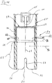
Fig. 11 das obere Rohrende eines Antriebsgehäuserohrs in Längsschnittdarstellung, -
Fig. 12 eine Draufsicht auf das Antriebsgehäuserohr in Richtung des Pfeiles XII inFig. 11 , -
Fig. 13 einen Querschnitt entsprechend Linie XIII-XIII inFig. 11 , -
Fig. 14 eine schematische Darstellung des unteren Endes eines zum hantieren eines Verschlussstopfens dienenden Werkzeugs. - Eine Vorrichtung der erfindungsgemäßen Art, welche neben einem Verschlussstopfen auch ein zu dessen Handhabung dienendes Werkzeug umfasst, dient zum Verschließen eines Antriebsgehäuserohrs 1, welches, wie in
Fig. 1 schematisch gezeigt, eine Öffnung 2 im Boden 3 eines Reaktordruckbehälters 4 durchgreift. Das Antriebsgehäuserohr 1 steht dabei mit seinem oberen Endabschnitt 5 in den Innenraum 6 des Reaktordruckbehälters hinein. Mit der in Rede stehenden Vorrichtung wird die obere Rohröffnung 7 des Antriebsgehäuserohrs 1 verschlossen. - Der dazu dienende Verschlussstopfen 8, welcher in
Fig. 2 bis Fig. 10 gezeigt ist, umfasst ein nach unten offenes, also eine unterseitige Öffnung 9 aufweisendes Stopfengehäuse 10, ein axial beweglich innerhalb des Stopfengehäuses 10 geführtes Dichtelement 13 sowie ein Verriegelungselement 14. Das Dichtelement 13 weist eine Dichtfläche 15 auf, die so gestaltet ist, dass sie dichtend an einer Gegenfläche 16 des Rohrendes 5, welche die Rohröffnung 7 umgrenzt, anliegen kann. Die Gegenfläche 7 ist beispielsweise eine sich nach oben erweiternde Konusfläche. Dementsprechend ist die Dichtfläche 15 als eine sich nach unten verjüngende Konusfläche ausgebildet. Das Dichtelement 13 ist bezüglich der Mittellängsachse 17 des Verschlussstopfens 8 beweglich am Stopfengehäuse 10 gelagert und koaxial zur Mittellängsachse 17 ausgerichtet. An der Oberseite des etwa als Kegelstumpf ausgebildeten Dichtelements 13 ist ein sich nach oben weg erstreckender, koaxial zur Mittellängsachse 17 ausgerichteter Führungszapfen 19 angeordnet. Dessen oberes Ende ist durch eine Öffnung 20 in einer oberen, sich quer zur Mittellängsachse 17 erstreckenden Wand 23 mit axialer Beweglichkeit hindurch geführt. Die obere Stirnseite des Führungszapfens 19 ist mit einem gegenüber dessen Durchmesser verbreiteten Kopf 24, der an der Oberseite der Wand 23 des Stopfengehäuses 10 anliegt, z.B. mit Hilfe einer Schraube 25 verbunden. Innerhalb des Stopfengehäuses 10 ist eine beispielsweise als Schraubendruckfeder ausgebildete Feder 26 angeordnet, wobei diese den Führungszapfen koaxial umgreift und sich mit ihrem oberen Ende am Stopfengehäuse 10, nämlich an dessen Wand 23, und mit ihrem unteren Ende an der Oberseite des Dichtelements 13 abstützt. Das Dichtelement ist auf diese Weise in eine untere Endlage vorgespannt (Fig.3 ). Das Dichtelement 13, das eine kreisrunde Querschnittsform aufweist, ist in Radialrichtung bzw. in einer sich quer zur Mittellängsachse 17 erstreckenden Richtung so bemessen, dass zwischen ihm und der Innenwandung des Stopfengehäuses 10 ein Ringspalt 27 vorhanden ist. Das Dichtelement 13 weist weiterhin einen sich nach unten öffnenden zentralen Hohlraum 28 auf. In Fällen, in denen innerhalb des Antriebsgehäuserohrs 1 noch ein Teil des Antriebs vorhanden ist, kann ein bis an den Bereich der Gegenfläche 16 heranreichender oberer Abschnitt des Antriebsteils von dem Hohlraum 28 aufgenommen werden, so dass das Dichtelement 13 nicht an dem Antriebsteil anstößt und dadurch eine dichtende Anlage der Dichtfläche 15 an der Gegenfläche 16 verhindert wäre. Das Stopfengehäuse 10 weist eine zylindrische Seitenwand 29 auf, wobei der von der Seitenwand 29 umgrenzte Innenraums quer zur Mittellängsachse 17 derart bemessen ist, dass das Stopfengehäuse 10 auf den oberen Rohrabschnitt 5 bzw. auf den sich an die Rohröffnung 7 nach unten anschließenden Rohrabschnitt 30 des Antriebsgehäuserohrs 1 behinderungsfrei aufgesteckt werden kann. - Die axiale Fixierung des Verschlussstopfens am oberen Endabschnitt 5 erfolgt mit Hilfe des Verriegelungselements 14. Dieses ist bezüglich der Mittellängsachse 17 zwischen einer Verriegelungsstellung, in der es axial wirksam am Antriebsgehäuserohr 1 fixiert ist und einer Freigabestellung, in der die Axialfixierung aufgehoben ist, drehbar am Stopfengehäuse 10 gelagert, wobei die Mittellängsachse 17 die Drehachse ist. Das Verriegelungselement 14 weist weiterhin wenigstens eine radial nach innen vorstehende und nach oben weisende Anschlagfläche 33 auf, welche zum Hintergreifen einer nach unten weisenden Gegenfläche 34 am oberen Endabschnitt 5 bzw. am Rohrabschnitt 30 dient. Genauer gesagt ist das Verriegelungselement 14 ein Ring mit insgesamt vier, sich jeweils paarweise diametral gegenüberliegende Anschlagflächen 33, wobei diese einen Teil der Oberseite von radial nach innen vorstehenden Ringsegmenten 35 bilden. Zwischen zwei sich in Umfangsrichtung benachbarten Ringsegmenten 35 ist jeweils eine Ausnehmung 36 vorhanden.
- Zur drehbaren Lagerung am Stopfengehäuse liegt das ringförmige Verriegelungselement 14 in einer in der Innenwandung des Stopfengehäuses 10 vorhandenen Ringnut 37 ein. In der Innenwandung des Stopfengehäuses 10 sind außerdem sich in Axialrichtung bzw. in Richtung der Mittellängsachse 17 erstreckende Ausnehmungen 38 vorhanden. Die Ausnehmungen 38 erstrecken sich mit Teilbereichen 39a, 39b nach oben bzw. nach unten von der Ringnut 37 weg. Die Breite 40 der Ausnehmungen 39 entspricht der Breite 43 der am Verriegelungselement 14 vorhandenen Ausnehmungen 36. Die einander zugewandten Innenseiten der Ringsegmente 35 verlaufen auf einer Zylinderfläche (in den Abbildungen nicht dargestellt) deren Durchmesser 44 dem Durchmesser 45 der Innenwandung des Stopfengehäuses 10 entspricht, wobei letzterer in einem sich unmittelbar nach oben und unten an die Ringnut 37 anschließenden Wandungsbereich der Seitenwand 29 des Stopfengehäuses gemessen ist.
- Das Verriegelungselement 14 ist drehbar in der Ringnut 37 gehalten. In einer ersten Drehstellung, welche der oben genannten Freigabestellung entspricht, sind die Ausnehmungen 36 deckungsgleich mit den Ausnehmungen 38 des Stopfengehäuses. In der Verriegelungsstellung (
Fig. 3 ) ist das Verriegelungselement 14 gegenüber dem Stopfengehäuse 10 so verdreht, dass die Ringsegmente 35 im Bereich der Ausnehmungen 38 des Stopfengehäuses 10 angeordnet sind. In dieser Stellung hintergreifen bzw. überlappen die Ringsegmente 35 mit ihrer jeweils nach oben weisenden Anschlagfläche 33 die Gegenflächen 34 am Antriebsgehäuserohr 1. Die Gegenflächen 34 sind die unteren Stirnseiten von sich in Richtung der Mittellängsachse 17 erstreckenden Rippen 46, die am Außenumfang des Rohrabschnitts 30 radial nach außen vorstehen und in Umfangsrichtung entsprechend den Ausnehmungen 36 des Verriegelungselements 14 beabstandet sind. Die Länge 47 der Rippen 46 entspricht der Länge 48 der sich von der Ringnut 37 nach oben weg erstreckenden Bereiche 39b der Ausnehmungen 38 des Stopfengehäuses 10. In der Freigabestellung des Verriegelungselements 14 kann somit der Verschlussstopfen 8 auf das Antriebsgehäuse 1 bzw. auf dessen Rohrabschnitt 30 aufgeschoben werden, wobei die Rippen 46 in die komplementär ausgestalteten Ausnehmungen 38 an der Innenwandung des Stopfengehäuses 10 eingreifen. Wenn der Verschlussstopfen seine Endstellung am Antriebsgehäuserohr 1 erreicht hat, befinden sich die Rippen 46 vollständig innerhalb der oberen Bereiche 39b der Ausnehmungen 38, ragen somit nicht in die Ringnut 37 hinein, sodass das Verriegelungselement mit seinen radial nach innen vorstehenden Ringsegmenten 35 unter die Gegenflächen 34 der Rippen 46 bewegt werden kann. - Um das Verriegelungselement 14 in seine verschiedenen Stellungen verfahren zu können, ist wenigstens ein mit einem Überstand 49 aus dem Außenumfang des Stopfengehäuses 10 vorstehendes Drehbetätigungselement 50 vorhanden. Bei dem zeichnerisch dargestellten Ausführungsbeispiel sind zwei Drehbetätigungselemente 50 vorhanden, die an sich diametral gegenüberliegenden Stellen an der Außenseite des ringförmigen Verriegelungselements 14 angeordnet sind. Die Drehbetätigungselemente 50 ragen durch ein sich in Umfangsrichtung des Stopfengehäuses 10 erstreckendes, dessen Seitenwand 29 durchgreifendes Langloch 53 hindurch. Das Langloch 53 weist eine Bogenlänge auf, welche dem Drehverstellweg des Verriegelungselements 14 entspricht.
- Die Drehbetätigung des Verriegelungselements erfolgt mit Hilfe eines Werkzeugs 54, welches an einem in einem Kraftwerk üblichen vertikal und horizontal verfahrbaren Mast (nicht gezeigt) fixierbar und mit diesem axial verfahrbar ist. Das Werkzeug 54 umfasst ein eine untere Öffnung 56 aufweisendes Montagerohr 55. Ein sich an die untere Öffnung 56 nach oben anschließender Rohrabschnitt bildet eine einen kreisrunden Innenquerschnitt aufweisende Aufnahme 57 für den Verschlussstopfen 8. Außerdem umfasst der genannte Rohrabschnitt ein Koppelelement 58, welches zur Drehbewegung des Verriegelungselements 14 mit einem Drehbetätigungselement 50 zusammenwirkt. Bei dem in
Figur 14 dargestellten Ausführungsbeispiel eines Werkzeugs 54 ist das Koppelelement 58 ein sich in Axialrichtung erstreckender, in die untere Stirnseite 52 des Montagerohrs 55 ausmündender Schlitz in der Innenwandung der Aufnahme 57, wobei dieser sich radial nach außen in die Rohrwand des Montagerohrs 55 hinein erstreckt und diese auch durchdringen kann. Der Übergang zwischen der Stirnseite 52 und dem schlitzförmigen Koppelelement 58 ist in Form einer Einführschräge 51 ausgebildet. Bei der Anbringung eines Stopfens an dem Antriebsgehäuserohr 1 ragt das Drehbetätigungselement 50 des Verriegelungselements 14 in das als Schlitz ausgebildete Koppelelement 58 hinein oder durchsetzt dieses. - Zur axialen Fixierung des Verschlussstopfens 8 innerhalb des Montagerohrs 55 ist oberhalb des Koppelelements 58 ein Greifer 59 zwischen einer oberen Axialposition P/o und einer unteren Axialposition P/u verstellbar angeordnet. Der Greifer 59 fixiert in der oberen Axialposition P/o den Verschlussstopfen 8 und gibt diesen in der unteren Axialposition P/u frei. Zur Fixierung des Verschlussstopfens 8 weist der Greifer 59 wenigstens ein Greifelement 60 auf, das in der unteren Axialposition unter Ausbildung eines axial wirksamen Formschlusses mit einer Fixierausnehmung 63 des Stopfengehäuses 10 zusammenwirkt. In der unteren Axialposition P/u stehen die Greifelemente 60 bezüglich der Mittellängsachse (61) des Montagerohrs 55 weiter nach innen vor als in der oberen Axialposition P/o. Wird somit der Greifer 59 innerhalb des Montagerohres 55 axial nach unten bewegt, bewegen sich die Greifelemente 60 radial nach innen und erfassen den Verschlussstopfen 8, indem sie ein nach unten weisende Fläche des Verschlussstopfens 8 hintergreifen. Die genannte Fläche wird im vorliegenden Ausführungsbeispiel von der Unterseite der den Verschlussstopfen 8 oberseits abschließenden Wand 23 gebildet. Die radial nach innen gerichtete Bewegung der Greifelemente 60 wird mit Hilfe eines von der Innenwandung des Montagerohrs 55 radial nach innen vorstehenden Vorsprungs 64, der im Ausführungsbeispiel nach
Fig. 14 eine sich nach unten verjüngende Konusfläche ist, bewirkt. - Zur axialen Bewegung des Greifers 59 zwischen der oberen und der unteren Axialposition P/o, P/u, ist innerhalb des Montagerohrs 55 oberhalb des Greifers 59 an ein Antrieb 65 beispielsweise in Form eines Hydraulikzylinders angeordnet. Dessen nach unten gerichtete Kolbenstange 66 ist mit dem Greifer 59 verbunden. Dieser umfasst beispielsweise eine kreisrunde Grundplatte 67, an der randständig zwei sich diametral gegenüberliegende, nach unten weg erstreckende Arme 71 angeordnet sind. Deren Freienden bilden die Greifelemente 60, wobei diese auf ihren einander zugewandten Innenseiten eine Mulde 62 aufweisen, um die Greifeigenschaften des Greifers 59 zu verbessern.
- Zum Verschluss der Rohröffnung 7 eines Antriebsgehäuserohrs 1 wird das Werkzeug 54, in dessen Aufnahme 57 sich ein Verschlussstopfen 8 befindet, mit Hilfe des oben genannten Mastes in den Innenraum des Reaktordruckbehälters abgesenkt. Der Verschlussstopfen 8 ist mit Hilfe des Greifers 59, der sich in seiner unteren Axialposition P/u befindet relativ zum Montagerohr axial gehalten. Die Drehbetätigungselemente 50 ragen jeweils in ein schlitzförmiges Koppelelement 58 hinein. Der Verschlussstopfen 8 befindet sich dabei gegenüber dem Koppelelement 58 in einer Drehposition, bei der sich das ringförmige Verriegelungselement 14 in seiner Freigabestellung befindet.
- Der Verschlussstopfen kann somit mit seinen Ausnehmungen 38 auf die sich axial erstreckenden Rippen 46 des Antriebsgehäuses 1 aufgeschoben werden. Dabei wird das Dichtelement 13 mit seiner Dichtfläche 15 unter axialer Kompression der Feder 26 gegen die Gegenfläche 16 am Antriebsgehäuserohr 1 gedrückt. Die Endposition dieser Aufschiebebewegung ist dann erreicht, wenn das Stopfengehäuse 10 mit seiner unteren Stirnseite an einer radial nach außen vorstehenden Schulter 68 des Antriebsgehäuses 1 anstößt. Das Montagerohr 55 wird dann um seine Mittellängsachse 61 gedreht und dadurch das Verriegelungselement 14 in seine Verriegelungsstellung gelangt. Die Ringsegmente 35 hintergreifen dann mit ihren Anschlagflächen 33 die Gegenflächen 34 der Rippen 46, also deren unteren Stirnseiten. Als nächster Schritt wird der Greifer mit Hilfe des Antriebs 65 in seine obere Axialposition P/o bewegt und das Werkzeug 54 mit Hilfe des Mastes angehoben.
- Eine Demontage des Verschlussstopfens 8 ist auf ebenso einfache Weise durchführbar, wenn die geschilderten Maßnahmen zum Verschluss des Antriebsgehäuserohrs 1 in umgekehrter Reihenfolge durchgeführt werden.
- Das Stopfengehäuse 10 ist zur Vereinfachung der Montage des Verschlussstopfenes 8 in zwei Teilgehäuse 10a, 10b unterteilt, wobei deren Trennfuge 69 in Richtung der Mittellängsachse 17 verläuft. Die Teilgehäuse sind als Gleichteile ausgestaltet. An ihrer im Montagezustand aneinander liegenden Montagefläche (70) sind Verbindungselemente beispielsweise in Form einer vorstehenden Lasche 73 und einer dazu komplementär ausgestalteten Vertiefung 74 an dem jeweils anderen Teilgehäuse 10a, 10b.
Claims (17)
- Vorrichtung zum Verschließen einer nach oben offenen Rohröffnung (7) eines den Steuerstabantrieb eines Siedewasserreaktors aufnehmenden Antriebsgehäuserohrs (1), umfassend einen Verschlussstopfen (8) mit einem nach unten offenen Stopfengehäuse (10), mit einem axial beweglich innerhalb des Stopfengehäuse geführten Dichtelement (13), das eine zur dichtenden Anlage an eine ringförmige, die Rohröffnung (7) umgrenzenden Gegenfläche (16) dienende Dichtfläche (15) aufweist, mit einem zur Fixierung des Stopfengehäuses (10) am Antriebsgehäuserohr (1) dienenden Verriegelungselement (14), und mit einer Feder (26), welche sich mit ihrem oberen Ende an dem Stopfengehäuse und mit ihrem unteren Ende am Dichtelement abstützt und dieses in einer unteren Endlage hält, wobei das Verriegelungselement (14) drehbar bezüglich der Mittellängsachse (17) des Verschlussstopfens (8) zwischen einer Verriegelungsstellung, in der es axial wirksam am Antriebsgehäuserohr (1) fixierbar ist, und einer Freigabestellung, in der die Axialfixierung aufgehoben ist, an dem Stopfengehäuse (10) gelagert ist.
- Vorrichtung nach Anspruch 1, wobei das Verriegelungselement (14) bezüglich der Mittellängsachse (17) wenigstens eine radial nach innen vorstehende und nach oben weisende Anschlagfläche (33) zum Hintergreifen einer nach unten weisenden Gegenfläche (34) am Antriebsgehäuserohr (1) aufweist.
- Vorrichtung nach Anspruch 2, wobei mehrere in Umfangsrichtung des Stopfengehäuses (10) verteilte Anschlagflächen (33) am Verriegelungselement (14) vorhanden sind.
- Vorrichtung nach Anspruch 3, wobei das Verriegelungselement (14) ein Ring ist und die Anschlagflächen (33) an radial nach innen vorstehenden Ringsegmenten (35)angeordnet sind, wobei zwei in Umfangsrichtung benachbarte Ringsegmente (35) eine Ausnehmung (36) zwischen sich einschließen.
- Vorrichtung einem der vorhergehenden Ansprüche, wobei das Verriegelungselement (14) wenigstens ein mit einem Überstand (49) aus dem Außenumfang des Stopfengehäuses (10) vorstehendes Drehbetätigungselement (50) aufweist.
- Vorrichtung nach Anspruch 5, wobei das Drehbetätigungselement (50) ein sich in Umfangsrichtung des Verschlussstopfens (8) erstreckendes Langloch (53) in einer sich koaxial zur Mittellängsachse (17) erstreckenden Seitenwand (29) des Stopfengehäuses (10) durchgreift.
- Vorrichtung nach einem der vorhergehenden Ansprüche, wobei das Stopfengehäuse (10) in mehrere Teilgehäuse (10, 10b) untergliedert ist, deren Trennfuge (69) in Richtung der Mittellängsachse (17) verläuft.
- Vorrichtung nach einem der vorhergehenden Ansprüche, wobei das Stopfengehäuse (10) eine kreisrunde Umrissform aufweist.
- Vorrichtung nach einem der vorhergehenden Ansprüche, wobei am Stopfengehäuse (10) wenigstens eine Fixierausnehmung (63) zum Greifen des Verschlussstopfens (8) mit Hilfe eines Greifers (59) vorhanden ist.
- Vorrichtung nach Anspruch 9, wobei die wenigstens eine Ausnehmung (63) in die Oberseite einer das Stopfengehäuse (10) nach oben hin abschließenden Wand (23) und in die Seitenwand (29) des Stopfengehäuses (10) mündet.
- Vorrichtung nach einem der Ansprüche 5 bis10, umfassend ein Werkzeug (54) zur Handhabung des Verschlussstopfens (8), mit einem eine untere Öffnung aufweisenden Montagerohr (55), wobei ein sich an die untere Öffnung (56) anschließender Rohrabschnitt eine Aufnahme (57) für den Verschlussstopfen (8) bildet und ein Koppelelement (58), wobei das Koppelelement zur Drehbewegung des Verriegelungselements (14) mit dessen wenigstens einem Drehbetätigungselement (50) zusammenwirkt.
- Vorrichtung nach Anspruch 11 in Verbindung mit Anspruch 5, wobei das Koppelelement (58) eine in der Innenwandung des Montagerohrs (55) vorhandene, in dessen untere Stirnseite ausmündende Ausnehmung ist, in die das Drehbetätigungselement (50) des Verschlussstopfens (14) eingreift.
- Vorrichtung nach Anspruch 12, wobei das Koppelelement (58) ein sich in Längsrichtung des Montagerohrs (55) erstreckender Schlitz ist.
- Vorrichtung nach einem der Ansprüche 11 bis 13, wobei innerhalb des Montagerohrs (55) an einer oberhalb des wenigstens einen Koppelelements (58) ein Greifer (59) zur axialen Fixierung des Verschlussstopfens (8) vorhanden ist, welcher zwischen einer oberen und einer unteren Axialposition verfahrbar ist, wobei er in der unteren Axialposition (P/u) den Verschlussstopfen (8) axial fixiert und in der oberen Axialposition (P/0)den Verschlussstopfen (8) freigibt.
- Vorrichtung nach Anspruch 14 in Verbindung mit Anspruch 10 oder 11, wobei der Greifer (59) wenigstens ein Greifelement (60) aufweist, das in der unteren Axialposition unter Ausbildung eines axial wirksamen Formschlusses in die wenigstens eine Fixierausnehmung (63) des Stopfengehäuses (10) eingreift.
- Vorrichtung nach Anspruch 15, wobei der Greifer (59) wenigstens ein axial nach unten abstehende flexibles Greifelement (60) umfasst, wobei dieses bezüglich der Mittellängsachse (61) des Montagerohrs (55) in der oberen Axialposition (P/o) radial weiter außen angeordnet ist als in der unteren Axialposition (P/u).
- Vorrichtung nach Anspruch 16, wobei das Greifelement (60) in der unteren Axialposition (P/u) an einem von der Innenwandung des Montagerohrs (55) vorstehenden Vorsprung (64) anliegt.
Applications Claiming Priority (2)
| Application Number | Priority Date | Filing Date | Title |
|---|---|---|---|
| DE102012216833A DE102012216833B3 (de) | 2012-09-19 | 2012-09-19 | Vorrichtung zum Verschließen eines Antriebsgehäuserohrs |
| PCT/EP2013/066721 WO2014044468A1 (de) | 2012-09-19 | 2013-08-09 | VORRICHTUNG ZUM VERSCHLIEßEN EINES ANTRIEBSGEHÄUSEROHRS |
Publications (2)
| Publication Number | Publication Date |
|---|---|
| EP2898513A1 EP2898513A1 (de) | 2015-07-29 |
| EP2898513B1 true EP2898513B1 (de) | 2017-01-11 |
Family
ID=49083643
Family Applications (1)
| Application Number | Title | Priority Date | Filing Date |
|---|---|---|---|
| EP13753827.8A Active EP2898513B1 (de) | 2012-09-19 | 2013-08-09 | Vorrichtung zum verschliessen eines antriebsgehäuserohrs |
Country Status (6)
| Country | Link |
|---|---|
| US (1) | US9922735B2 (de) |
| EP (1) | EP2898513B1 (de) |
| JP (1) | JP6251747B2 (de) |
| DE (1) | DE102012216833B3 (de) |
| ES (1) | ES2621348T3 (de) |
| WO (1) | WO2014044468A1 (de) |
Family Cites Families (18)
| Publication number | Priority date | Publication date | Assignee | Title |
|---|---|---|---|---|
| GB1084319A (de) * | ||||
| GB190714606A (en) | 1907-06-25 | 1907-10-31 | John Ridley | A New or Improved Self-locking Lid or Cap. |
| GB722040A (en) | 1951-04-16 | 1955-01-19 | Svenska Maskinverken Ab | Improvements in and relating to tools for sealing the ends of tubular elements subjected to internal pressure |
| DE911565C (de) | 1952-12-20 | 1954-05-17 | Koerting Maschinen Und Appbau | Schnellverschluss zum Verschliessen einer kreisfoermigen OEffnung an Kesseln und Behaeltern |
| DE1227741B (de) | 1960-12-20 | 1966-10-27 | Siemens Ag | Abnehmbarer Verschluss fuer Druckrohre von Kernreaktoren |
| FR1502750A (fr) | 1966-08-05 | 1967-11-24 | Commissariat Energie Atomique | Bouchon d'obturation |
| FR1564926A (de) | 1968-03-15 | 1969-04-25 | ||
| DE3228802C2 (de) | 1982-08-02 | 1986-08-28 | Kraftwerk Union AG, 4330 Mülheim | De- und remontable Abdichteinrichtung und ein Verfahren zur Vorbereitung der Abdichtung von Rohrleitungen, insbesondere der Hauptkühlmittelstutzen eines Reaktordruckbehälters |
| JPS6291091U (de) * | 1985-11-29 | 1987-06-10 | ||
| US4888151A (en) | 1988-08-17 | 1989-12-19 | Westinghouse Electric Corp. | Reconstitutable control assembly having removable control rods with detachable split upper end plugs |
| US5227124A (en) * | 1989-08-04 | 1993-07-13 | Hitachi, Ltd. | Method and structure for preventive maintaining an elongated metal hollow member |
| FR2668215B1 (fr) | 1990-10-23 | 1993-07-30 | Cogema | Dispositif de raccordement a bauionnette et perche equipee d'un tel dispositif. |
| JPH0635996U (ja) * | 1992-10-09 | 1994-05-13 | 石川島播磨重工業株式会社 | 原子炉圧力容器の水圧プラグ |
| CA2202944A1 (en) | 1996-05-06 | 1997-11-06 | Douglas M. Mclelland | Closure plug with bonded gasket |
| JP3869062B2 (ja) * | 1997-02-12 | 2007-01-17 | 株式会社東芝 | 圧力容器開口部の閉鎖装置 |
| US7206372B2 (en) * | 2002-07-15 | 2007-04-17 | General Electric Company | Methods of repairing leaking elongate hollow members in boiling water reactors |
| US7303089B2 (en) * | 2004-10-21 | 2007-12-04 | Keller Russell D | Anti-siphon fuel cap and filler tube assembly |
| KR101296210B1 (ko) * | 2008-10-03 | 2013-08-13 | 가부시끼가이샤 도시바 | 원자로 노 저부의 보수 방법 |
-
2012
- 2012-09-19 DE DE102012216833A patent/DE102012216833B3/de not_active Expired - Fee Related
-
2013
- 2013-08-09 US US14/427,245 patent/US9922735B2/en active Active
- 2013-08-09 JP JP2015532346A patent/JP6251747B2/ja active Active
- 2013-08-09 ES ES13753827.8T patent/ES2621348T3/es active Active
- 2013-08-09 WO PCT/EP2013/066721 patent/WO2014044468A1/de not_active Ceased
- 2013-08-09 EP EP13753827.8A patent/EP2898513B1/de active Active
Non-Patent Citations (1)
| Title |
|---|
| None * |
Also Published As
| Publication number | Publication date |
|---|---|
| US9922735B2 (en) | 2018-03-20 |
| JP6251747B2 (ja) | 2017-12-20 |
| US20150243381A1 (en) | 2015-08-27 |
| WO2014044468A1 (de) | 2014-03-27 |
| ES2621348T3 (es) | 2017-07-03 |
| EP2898513A1 (de) | 2015-07-29 |
| DE102012216833B3 (de) | 2013-10-24 |
| JP2015534057A (ja) | 2015-11-26 |
Similar Documents
| Publication | Publication Date | Title |
|---|---|---|
| EP2861388B1 (de) | Greifer | |
| AT512397B1 (de) | Steckverbindung zum Verbinden von Leitungen für unter Druck gesetzte Flüssigkeiten oder Gase | |
| EP2439439B1 (de) | Verbindungselement für eine Fluidverbindung | |
| DE112012003763B4 (de) | Restdruckentlastungsventil | |
| DE2845515A1 (de) | Endhalterung fuer ein kernreaktor- brennelement | |
| DE102010039803A1 (de) | Blasform | |
| EP3356697B1 (de) | Bauteil der hebe-, zurr- oder anschlagtechnik, insbesondere schäkel, für outdoor- oder offshore-anwendungen | |
| WO2002047213A1 (de) | Kupplung zur explosionssicheren verbindung von zwei elektrischen leitungsenden | |
| DE1065103B (de) | Kontrollstabeinheit fuer Kernreaktoren | |
| DE102011051842A1 (de) | Befüllkopf zum Einfüllen einer Flüssigkeit in einen Tankstutzen | |
| DE3720018A1 (de) | Federnspanner | |
| EP2796646B1 (de) | Hangschloss | |
| DE1284765B (de) | Sicherheitsverriegelung fuer den Verschlussstopfen von Druckbehaeltern oder Druckrohren | |
| WO2018019422A1 (de) | Halteelement und anschlussverbinder mit einem solchen | |
| DE102010032527A1 (de) | Verschlussanordnung für einen Betriebsmittelbehälter | |
| DE102020115021A1 (de) | Vorrichtung zum Verbinden zweier röhrenförmiger Objekte | |
| EP2898513B1 (de) | Vorrichtung zum verschliessen eines antriebsgehäuserohrs | |
| DE4200452C2 (de) | Wechselarmatur für das Einführen von Meßsonden in das in einem unter Druck stehenden Behälter befindliche Medium | |
| EP3529526B1 (de) | Befülleinrichtung zum befüllen eines fluidspeichers sowie vorrichtung zum kuppeln der befülleinrichtung mit einem befüllkanal des fluidspeichers | |
| DE2241608A1 (de) | Werkzeughalter | |
| DE68903538T2 (de) | Regelspinne mit demortierbaren staeben fuer ein kernbrennstabbuendel. | |
| CH635201A5 (de) | Vorrichtung zum halten von laengsbelasteten pruefkoerpern in einem rohr und zum verschliessen desselben. | |
| DE3401391A1 (de) | Steckverbindung mit einem muffenteil und einem steckerteil als loesbar miteinander verbindbaren kupplungselementen, insbesondere fuer stroemungsmittelkupplungen | |
| EP0187238B1 (de) | Auch bei unter Druck stehendem Stecker kuppelbare Rohrabreisskupplung für insbes. Hydraulikleitungen | |
| DE102007041582A1 (de) | Anhängekupplung |
Legal Events
| Date | Code | Title | Description |
|---|---|---|---|
| PUAI | Public reference made under article 153(3) epc to a published international application that has entered the european phase |
Free format text: ORIGINAL CODE: 0009012 |
|
| 17P | Request for examination filed |
Effective date: 20150225 |
|
| AK | Designated contracting states |
Kind code of ref document: A1 Designated state(s): AL AT BE BG CH CY CZ DE DK EE ES FI FR GB GR HR HU IE IS IT LI LT LU LV MC MK MT NL NO PL PT RO RS SE SI SK SM TR |
|
| AX | Request for extension of the european patent |
Extension state: BA ME |
|
| DAX | Request for extension of the european patent (deleted) | ||
| REG | Reference to a national code |
Ref country code: DE Ref legal event code: R079 Ref document number: 502013006081 Country of ref document: DE Free format text: PREVIOUS MAIN CLASS: G21C0013067000 Ipc: G21C0007120000 |
|
| GRAP | Despatch of communication of intention to grant a patent |
Free format text: ORIGINAL CODE: EPIDOSNIGR1 |
|
| RIC1 | Information provided on ipc code assigned before grant |
Ipc: G21C 13/067 20060101ALI20160613BHEP Ipc: G21C 7/12 20060101AFI20160613BHEP |
|
| INTG | Intention to grant announced |
Effective date: 20160704 |
|
| GRAJ | Information related to disapproval of communication of intention to grant by the applicant or resumption of examination proceedings by the epo deleted |
Free format text: ORIGINAL CODE: EPIDOSDIGR1 |
|
| GRAP | Despatch of communication of intention to grant a patent |
Free format text: ORIGINAL CODE: EPIDOSNIGR1 |
|
| INTC | Intention to grant announced (deleted) | ||
| INTG | Intention to grant announced |
Effective date: 20160822 |
|
| GRAS | Grant fee paid |
Free format text: ORIGINAL CODE: EPIDOSNIGR3 |
|
| GRAA | (expected) grant |
Free format text: ORIGINAL CODE: 0009210 |
|
| AK | Designated contracting states |
Kind code of ref document: B1 Designated state(s): AL AT BE BG CH CY CZ DE DK EE ES FI FR GB GR HR HU IE IS IT LI LT LU LV MC MK MT NL NO PL PT RO RS SE SI SK SM TR |
|
| REG | Reference to a national code |
Ref country code: GB Ref legal event code: FG4D Free format text: NOT ENGLISH |
|
| REG | Reference to a national code |
Ref country code: CH Ref legal event code: EP |
|
| REG | Reference to a national code |
Ref country code: AT Ref legal event code: REF Ref document number: 861929 Country of ref document: AT Kind code of ref document: T Effective date: 20170115 |
|
| REG | Reference to a national code |
Ref country code: IE Ref legal event code: FG4D Free format text: LANGUAGE OF EP DOCUMENT: GERMAN |
|
| REG | Reference to a national code |
Ref country code: DE Ref legal event code: R096 Ref document number: 502013006081 Country of ref document: DE |
|
| REG | Reference to a national code |
Ref country code: CH Ref legal event code: NV Representative=s name: E. BLUM AND CO. AG PATENT- UND MARKENANWAELTE , CH |
|
| REG | Reference to a national code |
Ref country code: SE Ref legal event code: TRGR |
|
| REG | Reference to a national code |
Ref country code: LT Ref legal event code: MG4D |
|
| REG | Reference to a national code |
Ref country code: NL Ref legal event code: MP Effective date: 20170111 |
|
| PG25 | Lapsed in a contracting state [announced via postgrant information from national office to epo] |
Ref country code: NL Free format text: LAPSE BECAUSE OF FAILURE TO SUBMIT A TRANSLATION OF THE DESCRIPTION OR TO PAY THE FEE WITHIN THE PRESCRIBED TIME-LIMIT Effective date: 20170111 |
|
| REG | Reference to a national code |
Ref country code: ES Ref legal event code: FG2A Ref document number: 2621348 Country of ref document: ES Kind code of ref document: T3 Effective date: 20170703 |
|
| PG25 | Lapsed in a contracting state [announced via postgrant information from national office to epo] |
Ref country code: NO Free format text: LAPSE BECAUSE OF FAILURE TO SUBMIT A TRANSLATION OF THE DESCRIPTION OR TO PAY THE FEE WITHIN THE PRESCRIBED TIME-LIMIT Effective date: 20170411 Ref country code: LT Free format text: LAPSE BECAUSE OF FAILURE TO SUBMIT A TRANSLATION OF THE DESCRIPTION OR TO PAY THE FEE WITHIN THE PRESCRIBED TIME-LIMIT Effective date: 20170111 Ref country code: IS Free format text: LAPSE BECAUSE OF FAILURE TO SUBMIT A TRANSLATION OF THE DESCRIPTION OR TO PAY THE FEE WITHIN THE PRESCRIBED TIME-LIMIT Effective date: 20170511 Ref country code: HR Free format text: LAPSE BECAUSE OF FAILURE TO SUBMIT A TRANSLATION OF THE DESCRIPTION OR TO PAY THE FEE WITHIN THE PRESCRIBED TIME-LIMIT Effective date: 20170111 Ref country code: GR Free format text: LAPSE BECAUSE OF FAILURE TO SUBMIT A TRANSLATION OF THE DESCRIPTION OR TO PAY THE FEE WITHIN THE PRESCRIBED TIME-LIMIT Effective date: 20170412 |
|
| PG25 | Lapsed in a contracting state [announced via postgrant information from national office to epo] |
Ref country code: LV Free format text: LAPSE BECAUSE OF FAILURE TO SUBMIT A TRANSLATION OF THE DESCRIPTION OR TO PAY THE FEE WITHIN THE PRESCRIBED TIME-LIMIT Effective date: 20170111 Ref country code: RS Free format text: LAPSE BECAUSE OF FAILURE TO SUBMIT A TRANSLATION OF THE DESCRIPTION OR TO PAY THE FEE WITHIN THE PRESCRIBED TIME-LIMIT Effective date: 20170111 Ref country code: PL Free format text: LAPSE BECAUSE OF FAILURE TO SUBMIT A TRANSLATION OF THE DESCRIPTION OR TO PAY THE FEE WITHIN THE PRESCRIBED TIME-LIMIT Effective date: 20170111 Ref country code: PT Free format text: LAPSE BECAUSE OF FAILURE TO SUBMIT A TRANSLATION OF THE DESCRIPTION OR TO PAY THE FEE WITHIN THE PRESCRIBED TIME-LIMIT Effective date: 20170511 Ref country code: BG Free format text: LAPSE BECAUSE OF FAILURE TO SUBMIT A TRANSLATION OF THE DESCRIPTION OR TO PAY THE FEE WITHIN THE PRESCRIBED TIME-LIMIT Effective date: 20170411 |
|
| REG | Reference to a national code |
Ref country code: DE Ref legal event code: R097 Ref document number: 502013006081 Country of ref document: DE |
|
| PG25 | Lapsed in a contracting state [announced via postgrant information from national office to epo] |
Ref country code: RO Free format text: LAPSE BECAUSE OF FAILURE TO SUBMIT A TRANSLATION OF THE DESCRIPTION OR TO PAY THE FEE WITHIN THE PRESCRIBED TIME-LIMIT Effective date: 20170111 Ref country code: EE Free format text: LAPSE BECAUSE OF FAILURE TO SUBMIT A TRANSLATION OF THE DESCRIPTION OR TO PAY THE FEE WITHIN THE PRESCRIBED TIME-LIMIT Effective date: 20170111 Ref country code: SK Free format text: LAPSE BECAUSE OF FAILURE TO SUBMIT A TRANSLATION OF THE DESCRIPTION OR TO PAY THE FEE WITHIN THE PRESCRIBED TIME-LIMIT Effective date: 20170111 Ref country code: CZ Free format text: LAPSE BECAUSE OF FAILURE TO SUBMIT A TRANSLATION OF THE DESCRIPTION OR TO PAY THE FEE WITHIN THE PRESCRIBED TIME-LIMIT Effective date: 20170111 Ref country code: IT Free format text: LAPSE BECAUSE OF FAILURE TO SUBMIT A TRANSLATION OF THE DESCRIPTION OR TO PAY THE FEE WITHIN THE PRESCRIBED TIME-LIMIT Effective date: 20170111 |
|
| PLBE | No opposition filed within time limit |
Free format text: ORIGINAL CODE: 0009261 |
|
| STAA | Information on the status of an ep patent application or granted ep patent |
Free format text: STATUS: NO OPPOSITION FILED WITHIN TIME LIMIT |
|
| PG25 | Lapsed in a contracting state [announced via postgrant information from national office to epo] |
Ref country code: DK Free format text: LAPSE BECAUSE OF FAILURE TO SUBMIT A TRANSLATION OF THE DESCRIPTION OR TO PAY THE FEE WITHIN THE PRESCRIBED TIME-LIMIT Effective date: 20170111 Ref country code: SM Free format text: LAPSE BECAUSE OF FAILURE TO SUBMIT A TRANSLATION OF THE DESCRIPTION OR TO PAY THE FEE WITHIN THE PRESCRIBED TIME-LIMIT Effective date: 20170111 |
|
| 26N | No opposition filed |
Effective date: 20171012 |
|
| PG25 | Lapsed in a contracting state [announced via postgrant information from national office to epo] |
Ref country code: SI Free format text: LAPSE BECAUSE OF FAILURE TO SUBMIT A TRANSLATION OF THE DESCRIPTION OR TO PAY THE FEE WITHIN THE PRESCRIBED TIME-LIMIT Effective date: 20170111 |
|
| PG25 | Lapsed in a contracting state [announced via postgrant information from national office to epo] |
Ref country code: MC Free format text: LAPSE BECAUSE OF FAILURE TO SUBMIT A TRANSLATION OF THE DESCRIPTION OR TO PAY THE FEE WITHIN THE PRESCRIBED TIME-LIMIT Effective date: 20170111 |
|
| GBPC | Gb: european patent ceased through non-payment of renewal fee |
Effective date: 20170809 |
|
| REG | Reference to a national code |
Ref country code: FR Ref legal event code: ST Effective date: 20180430 |
|
| REG | Reference to a national code |
Ref country code: IE Ref legal event code: MM4A |
|
| REG | Reference to a national code |
Ref country code: BE Ref legal event code: MM Effective date: 20170831 |
|
| PG25 | Lapsed in a contracting state [announced via postgrant information from national office to epo] |
Ref country code: LU Free format text: LAPSE BECAUSE OF NON-PAYMENT OF DUE FEES Effective date: 20170809 |
|
| PG25 | Lapsed in a contracting state [announced via postgrant information from national office to epo] |
Ref country code: GB Free format text: LAPSE BECAUSE OF NON-PAYMENT OF DUE FEES Effective date: 20170809 Ref country code: IE Free format text: LAPSE BECAUSE OF NON-PAYMENT OF DUE FEES Effective date: 20170809 |
|
| PG25 | Lapsed in a contracting state [announced via postgrant information from national office to epo] |
Ref country code: FR Free format text: LAPSE BECAUSE OF NON-PAYMENT OF DUE FEES Effective date: 20170831 Ref country code: BE Free format text: LAPSE BECAUSE OF NON-PAYMENT OF DUE FEES Effective date: 20170831 |
|
| PG25 | Lapsed in a contracting state [announced via postgrant information from national office to epo] |
Ref country code: MT Free format text: LAPSE BECAUSE OF FAILURE TO SUBMIT A TRANSLATION OF THE DESCRIPTION OR TO PAY THE FEE WITHIN THE PRESCRIBED TIME-LIMIT Effective date: 20170111 |
|
| REG | Reference to a national code |
Ref country code: DE Ref legal event code: R082 Ref document number: 502013006081 Country of ref document: DE Representative=s name: MEISSNER BOLTE PATENTANWAELTE RECHTSANWAELTE P, DE Ref country code: DE Ref legal event code: R081 Ref document number: 502013006081 Country of ref document: DE Owner name: FRAMATOME GMBH, DE Free format text: FORMER OWNER: AREVA GMBH, 91052 ERLANGEN, DE |
|
| REG | Reference to a national code |
Ref country code: CH Ref legal event code: PUE Owner name: FRAMATOME GMBH, DE Free format text: FORMER OWNER: AREVA GMBH, DE |
|
| REG | Reference to a national code |
Ref country code: ES Ref legal event code: PC2A Owner name: FRAMATOME GMBH Effective date: 20190516 |
|
| PG25 | Lapsed in a contracting state [announced via postgrant information from national office to epo] |
Ref country code: HU Free format text: LAPSE BECAUSE OF FAILURE TO SUBMIT A TRANSLATION OF THE DESCRIPTION OR TO PAY THE FEE WITHIN THE PRESCRIBED TIME-LIMIT; INVALID AB INITIO Effective date: 20130809 |
|
| REG | Reference to a national code |
Ref country code: AT Ref legal event code: MM01 Ref document number: 861929 Country of ref document: AT Kind code of ref document: T Effective date: 20180809 |
|
| PG25 | Lapsed in a contracting state [announced via postgrant information from national office to epo] |
Ref country code: CY Free format text: LAPSE BECAUSE OF FAILURE TO SUBMIT A TRANSLATION OF THE DESCRIPTION OR TO PAY THE FEE WITHIN THE PRESCRIBED TIME-LIMIT Effective date: 20170111 |
|
| PG25 | Lapsed in a contracting state [announced via postgrant information from national office to epo] |
Ref country code: MK Free format text: LAPSE BECAUSE OF FAILURE TO SUBMIT A TRANSLATION OF THE DESCRIPTION OR TO PAY THE FEE WITHIN THE PRESCRIBED TIME-LIMIT Effective date: 20170111 |
|
| PG25 | Lapsed in a contracting state [announced via postgrant information from national office to epo] |
Ref country code: AT Free format text: LAPSE BECAUSE OF NON-PAYMENT OF DUE FEES Effective date: 20180809 |
|
| PG25 | Lapsed in a contracting state [announced via postgrant information from national office to epo] |
Ref country code: TR Free format text: LAPSE BECAUSE OF FAILURE TO SUBMIT A TRANSLATION OF THE DESCRIPTION OR TO PAY THE FEE WITHIN THE PRESCRIBED TIME-LIMIT Effective date: 20170111 |
|
| REG | Reference to a national code |
Ref country code: DE Ref legal event code: R082 Ref document number: 502013006081 Country of ref document: DE |
|
| PG25 | Lapsed in a contracting state [announced via postgrant information from national office to epo] |
Ref country code: AL Free format text: LAPSE BECAUSE OF FAILURE TO SUBMIT A TRANSLATION OF THE DESCRIPTION OR TO PAY THE FEE WITHIN THE PRESCRIBED TIME-LIMIT Effective date: 20170111 |
|
| P01 | Opt-out of the competence of the unified patent court (upc) registered |
Effective date: 20230419 |
|
| PGFP | Annual fee paid to national office [announced via postgrant information from national office to epo] |
Ref country code: ES Payment date: 20250908 Year of fee payment: 13 Ref country code: FI Payment date: 20250722 Year of fee payment: 13 |
|
| PGFP | Annual fee paid to national office [announced via postgrant information from national office to epo] |
Ref country code: DE Payment date: 20250812 Year of fee payment: 13 |
|
| PGFP | Annual fee paid to national office [announced via postgrant information from national office to epo] |
Ref country code: CH Payment date: 20250901 Year of fee payment: 13 Ref country code: SE Payment date: 20250826 Year of fee payment: 13 |