EP2898162B1 - A completely recessed door handle provided with lock - Google Patents
A completely recessed door handle provided with lock Download PDFInfo
- Publication number
- EP2898162B1 EP2898162B1 EP13776430.4A EP13776430A EP2898162B1 EP 2898162 B1 EP2898162 B1 EP 2898162B1 EP 13776430 A EP13776430 A EP 13776430A EP 2898162 B1 EP2898162 B1 EP 2898162B1
- Authority
- EP
- European Patent Office
- Prior art keywords
- door
- handle
- cursor
- pawl
- holding
- Prior art date
- Legal status (The legal status is an assumption and is not a legal conclusion. Google has not performed a legal analysis and makes no representation as to the accuracy of the status listed.)
- Active
Links
Images


Classifications
-
- E—FIXED CONSTRUCTIONS
- E05—LOCKS; KEYS; WINDOW OR DOOR FITTINGS; SAFES
- E05B—LOCKS; ACCESSORIES THEREFOR; HANDCUFFS
- E05B5/00—Handles completely let into the surface of the wing
-
- E—FIXED CONSTRUCTIONS
- E05—LOCKS; KEYS; WINDOW OR DOOR FITTINGS; SAFES
- E05B—LOCKS; ACCESSORIES THEREFOR; HANDCUFFS
- E05B5/00—Handles completely let into the surface of the wing
- E05B5/006—Handles completely let into the surface of the wing essentially defining a completely closed surface together with the wing
-
- E—FIXED CONSTRUCTIONS
- E05—LOCKS; KEYS; WINDOW OR DOOR FITTINGS; SAFES
- E05B—LOCKS; ACCESSORIES THEREFOR; HANDCUFFS
- E05B63/00—Locks or fastenings with special structural characteristics
- E05B63/04—Locks or fastenings with special structural characteristics for alternative use on the right-hand or left-hand side of wings
- E05B63/042—Locks or fastenings with special structural characteristics for alternative use on the right-hand or left-hand side of wings constructed symmetrically
-
- E—FIXED CONSTRUCTIONS
- E05—LOCKS; KEYS; WINDOW OR DOOR FITTINGS; SAFES
- E05C—BOLTS OR FASTENING DEVICES FOR WINGS, SPECIALLY FOR DOORS OR WINDOWS
- E05C1/00—Fastening devices with bolts moving rectilinearly
- E05C1/02—Fastening devices with bolts moving rectilinearly without latching action
- E05C1/06—Fastening devices with bolts moving rectilinearly without latching action with operating handle or equivalent member moving otherwise than rigidly with the bolt
- E05C1/065—Fastening devices with bolts moving rectilinearly without latching action with operating handle or equivalent member moving otherwise than rigidly with the bolt flush
-
- E—FIXED CONSTRUCTIONS
- E05—LOCKS; KEYS; WINDOW OR DOOR FITTINGS; SAFES
- E05C—BOLTS OR FASTENING DEVICES FOR WINGS, SPECIALLY FOR DOORS OR WINDOWS
- E05C19/00—Other devices specially designed for securing wings, e.g. with suction cups
- E05C19/16—Devices holding the wing by magnetic or electromagnetic attraction
- E05C19/163—Devices holding the wing by magnetic or electromagnetic attraction a movable bolt being held in the striker by a permanent magnet
-
- Y—GENERAL TAGGING OF NEW TECHNOLOGICAL DEVELOPMENTS; GENERAL TAGGING OF CROSS-SECTIONAL TECHNOLOGIES SPANNING OVER SEVERAL SECTIONS OF THE IPC; TECHNICAL SUBJECTS COVERED BY FORMER USPC CROSS-REFERENCE ART COLLECTIONS [XRACs] AND DIGESTS
- Y10—TECHNICAL SUBJECTS COVERED BY FORMER USPC
- Y10T—TECHNICAL SUBJECTS COVERED BY FORMER US CLASSIFICATION
- Y10T292/00—Closure fasteners
- Y10T292/57—Operators with knobs or handles
Definitions
- the present patent application for industrial invention relates to a completely recessed door handle provided with lock.
- a completely recessed door handle is a handle in which the holding lever and the support body of said holding lever do not protrude from the vertical surface of the door with unprecedented clean linear aesthetics.
- the models of door handles of known type comprise a bearing body wherein the locking bolt is slidingly housed, and whereon two identical holding levers of the handle are inserted from opposite sides, one on the internal side of the door, and one on the external side of the door.
- said body also houses a mechanism that is normally composed of a latch actuated by means of a key.
- said holding levers or knobs can accidentally hit the body or hook the clothes of people passing near the door, who may accidentally suffer injuries or tear their clothes.
- US2004/119294 discloses a flush latch locking mechanism for a door according to the preamble of claim 1.
- JP2005036403 discloses a lock reduced in projecting dimension from a door surface, this lock is formed so that a latch bolt is pulled inside by raising a knob from both sides of the door. With this structure, projecting dimension of this lock from the door surface when the lock is not operated is reduced.
- US3044815 discloses a latch mechanism comprising a frame carrying a retractable bolt.
- the frame is adapted for mounting in a door with a surface thereof substantially flush with the door.
- the purpose of the present invention is to remedy the aforesaid drawbacks, by devising a completely recessed door handle provided with lock, in which the holding levers do not protrude from the two opposite sides of the door.
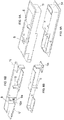
- the door handle of the invention comprises a substantially parallelepiped box-shaped body, having suitable dimensions to be recessed in the thickness of the door, in such manner that the two opposite longitudinal sides of said body are flush to the opposite sides of the door.
- the body houses a pair of identical L-shaped holding levers that revolve around pivoting pins with vertical axis, both cooperating with the same cursor or latch, composed of a plate that slides in horizontal direction and is provided with a window used to couple both said L-shaped holding levers.
- the holding levers do not protrude from said box-shaped body, at least until they are not pulled outwards to open the door.
- the body also houses a pawl sliding inside a guide channel along a horizontal direction, orthogonal to the sliding direction of said cursor or latch; said pawl is externally provided with a catch and is constantly subject to the recoil action of a return spring that tends to eject the pawl outwards, holding it in a first end-of-travel position that corresponds to a non-working position of said catch, which is adapted to engage, in a second end-of-travel position, with a counter-catch obtained on said holding levers, in such manner to determine an interference condition that hinders the opening of the external lever of the door when the internal lever is fitted to said pawl, which has been previously pressed until it reaches said second end-of-travel position, overcoming the antagonist force of said return spring.
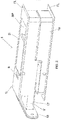
- the handle of the invention comprises a box-shaped body (1) with substantially parallelepiped shape, having suitable dimensions to be recessed into the thickness (s) of the door (P), in such manner that the opposite parallel pair of longitudinal sides (FL) of said body (1) are flush to the internal side (FI) and external side (FE) of the door (P), respectively.
- said two opposite longitudinal sides (FL) are flat and lie on a vertical plane.
- said box-shaped body (1) is obtained by specularly coupling two almost identical semi-bodies, one (1i) facing towards the internal side (FI) of the door, and one (1e) facing towards the external side (FE) of the door.
- Each of said semi-bodies (1i and 1e) acts as support for a holding lever (2), it being possible to distinguish an internal holding lever (2i) disposed on the internal side (FI) of the door and an external holding lever (2e) disposed on the external side (FE) of the door (P).
- each holding lever (2) has an L-shaped configuration, being formed of a first long arm (2a) and a second short arm (2b), orthogonal to the first arm (2a), wherein the first long arm (2a) extends - when the lever is not actuated and pulled - in parallel position flush to said opposite longitudinal sides (FL) of said body (1).
- the two opposite longitudinal sides (FL) of the body (1) are provided with two windows (1a) that are not completely covered by said long arm (2a), thus leaving a sufficient space (SP) to insert the tip of a finger and grab the holding lever (2), rotating it outwards as shown in Fig. 5 .
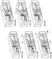
- Each holding lever (2) revolves around a pivoting pin (3) with vertical axis and is subject to the recoil force of a return spring (4) fixed in a point (P1) to the long arm (2a) and in a point (P2) to the body (1), which is also provided with a partition (5) adapted to act as stop for the lever (2), which is stopped and remains stopped against said partition (5) until it is not grabbed and pulled, as shown in Fig. 6A or 7 .
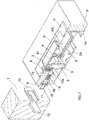
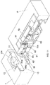
- the body (1) houses a cursor (6) that slides along a horizontal axis, which acts as stop latch, composed of a rectangular plate lying on a vertical plane and provided with a large rectangular window (7) inside which both short arms (2b) of the two holding levers (2) are engaged.
- said cursor (6) comprises:
- said window (7) comprises:
- the length "L" of the window (7) is such that - when the cursor (6) is in maximum forward travel condition - the back side (7b) of the window (7) is extremely close to the short side (2b) of both levers (2).
- the body (1) also houses a pawl (8) that slides inside a guide channel (9) along a horizontal direction, orthogonal to the sliding direction of said cursor (6).
- said pawl (8) has an empty structure and is externally provided with a cuneiform catch (8a) and constantly subject to the recoil action of a return spring (10) contained inside the empty structure of the pawl.
- each lever (2) is provided with a retention tooth (2b') adapted to be fixed to the catch (8a) in certain conditions.
- the spring (10) tends to eject the pawl (8) outwards, holding it in a first end-of-travel position (see Fig. 6F ) that corresponds to the non-working position of said catch (8a) adapted to engage with said retention tooth (2b') in a second end-of-travel position, in such manner to determine an interference condition (see Fig. 6C ) that hinders the opening rotation (R) of the external lever (2e) of the door, when the internal lever (2i) is fixed to said pawl (8), which has been previously pressed until it reaches said second end-of-travel position, overcoming the antagonist force of said return spring (10), as shown in Fig. 6B .
- the spring (10) is disposed between the bottom of the internal cavity of the pawl (8) and a fixed peg (10a) obtained on the internal semi-body (1i), as shown in Fig. 9B .
- the catch (8a) also acts as stop for the pawl (8) in maximum ejection condition under the thrust of the spring (10).
- the housing and guide channel (9) of said pawl (8) is provided with a back element (9a) against which the catch (8a) is stopped at the end of the ejection travel under the thrust of the spring (10).
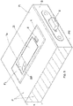
- the cursor (6) incorporates a magnet (11) that, when the door (P) is closed, is interfaced with an analogous magnet (12) incorporated in the back plate (13) mounted in the frame (T) of the door (P).
- the presence of the pair of magnets (11 and 12) determines the automatic forward travel of the cursor (6) every time the door (P) is closed, whereas the backward travel of said cursor (6) - which is indispensable to open the door (P) - requires the manual action of one of said holding levers (2i, 2e).
- the pawl (8) must be pressed in order to prevent the door from being freely opened by manually actuating one of the two holding levers (2i, 2e).
- a spring (14) is provided, the return force of which must be obviously lower than the attraction force between the magnets (11 and 12).
- said return spring (14) is housed inside a second window (15) obtained on the cursor (6) near said first window (7), as shown in Figs. 4 and 7 .
- the spring (14) is disposed between one of the transversal sides of the window (15) and a fixed peg (16) joined to the body (1), as shown in Fig. 7 .
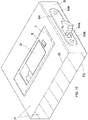
- the cursor (6) is housed and slides inside a compartment (V) obtained on the internal semi-body (1i); said compartment (V) is internally closed with a rectangular plate (17), as clearly shown in Fig. 2 , whereas it is frontally closed by a plate (18) provided with central slot to allow the cursor (6) to come out.
- the door handle of the invention can be realized in two different versions, one for hinged doors, and one for sliding doors.
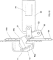
- the holding levers (2) are coupled with a cursor (60) provided with a window (70) where the short arms (2b) of both holding levers (2) are inserted.
- the cursor (60) is connected, by means of a small connecting rod (61), to a fastener (62) that is provided at one end with a hook (62a), whereas at the other end it is provided with a hole to receive a pivoting pin (63) through which said fastener (62) is hinged to a plate (64) provided with a central slot (64a) to let said hook (62a) come out and with an opposite pair of holes (64b) for fixing on the rib (B) of the door (P).
- said hook (62a) incorporates a magnet (11) that, when the door (P) is closed, is interfaced with an analogous magnet (12) incorporated in the back plate (13) mounted in the frame (T) of the door (P) and provided with a curved seating (13a) for hooking of said hook (62a).
Landscapes
- Engineering & Computer Science (AREA)
- Mechanical Engineering (AREA)
- Structural Engineering (AREA)
- Physics & Mathematics (AREA)
- Electromagnetism (AREA)
- Casings For Electric Apparatus (AREA)
- Lock And Its Accessories (AREA)
- Wing Frames And Configurations (AREA)
- Walking Sticks, Umbrellas, And Fans (AREA)
- Details Of Rigid Or Semi-Rigid Containers (AREA)
Priority Applications (1)
| Application Number | Priority Date | Filing Date | Title |
|---|---|---|---|
| PL13776430T PL2898162T3 (pl) | 2012-09-24 | 2013-09-23 | Całkowicie wpuszczona klamka drzwi wyposażona w zamek |
Applications Claiming Priority (2)
| Application Number | Priority Date | Filing Date | Title |
|---|---|---|---|
| IT000119A ITAN20120119A1 (it) | 2012-09-24 | 2012-09-24 | Maniglia per porte, completamente ad incasso e corredata di serratura. |
| PCT/EP2013/069743 WO2014044850A1 (en) | 2012-09-24 | 2013-09-23 | A completely recessed door handle provided with lock |
Publications (2)
| Publication Number | Publication Date |
|---|---|
| EP2898162A1 EP2898162A1 (en) | 2015-07-29 |
| EP2898162B1 true EP2898162B1 (en) | 2018-11-07 |
Family
ID=47016735
Family Applications (1)
| Application Number | Title | Priority Date | Filing Date |
|---|---|---|---|
| EP13776430.4A Active EP2898162B1 (en) | 2012-09-24 | 2013-09-23 | A completely recessed door handle provided with lock |
Country Status (13)
| Country | Link |
|---|---|
| US (1) | US20150225979A1 (pl) |
| EP (1) | EP2898162B1 (pl) |
| JP (1) | JP2015529291A (pl) |
| CN (1) | CN104662241B (pl) |
| AU (1) | AU2013320162A1 (pl) |
| CA (1) | CA2885286A1 (pl) |
| ES (1) | ES2709330T3 (pl) |
| HK (1) | HK1213033A1 (pl) |
| IT (1) | ITAN20120119A1 (pl) |
| PL (1) | PL2898162T3 (pl) |
| RU (1) | RU2635295C2 (pl) |
| TR (1) | TR201901699T4 (pl) |
| WO (1) | WO2014044850A1 (pl) |
Families Citing this family (18)
| Publication number | Priority date | Publication date | Assignee | Title |
|---|---|---|---|---|
| USD874243S1 (en) | 2011-06-21 | 2020-02-04 | Jaguar Land Rover Limited | Vehicle door handle |
| GB2492319A (en) | 2011-06-21 | 2013-01-02 | Jaguar Cars | Retractable handle |
| KR101663893B1 (ko) * | 2015-03-26 | 2016-10-07 | 임효빈 | 매립형 도어록 |
| JP7041458B2 (ja) * | 2015-11-10 | 2022-03-24 | 三協立山株式会社 | 建具 |
| USD806506S1 (en) * | 2015-12-08 | 2018-01-02 | Architectural Builders Hardware Mfg., Inc. | Door handle with recess |
| EP3234284B1 (en) * | 2016-03-09 | 2018-07-25 | Pirnar, trzenje, proizvodnja in razvoj, d.o.o. | Door handle assembly and process for extending and retracting of door handle assembly |
| WO2017198305A1 (de) * | 2016-05-19 | 2017-11-23 | Form Orange Produktentwicklung | TÜRSCHLIEßMECHANISMUS MIT EINER IM TÜRRAHMEN EINGELASSENEN AUFNAHME FÜR DEN SCHLIEßRIEGEL EINER IN DIE TÜR EINGELASSENEN VORRICHTUNG ZUM STEUERN DES SCHLIEßRIEGELS IN DIE ÖFFNUNGSSTELLUNG MITTELS EINES MANUELL STEUERBAREN BETÄTIGUNGSGLIEDS |
| US10550610B2 (en) * | 2016-06-22 | 2020-02-04 | Ford Global Technologies, Llc | Inside override emergency handle for door release |
| JP6631464B2 (ja) * | 2016-10-20 | 2020-01-15 | トヨタ自動車株式会社 | インサイドドアハンドル構造 |
| JP6853548B2 (ja) * | 2016-11-24 | 2021-03-31 | 大建工業株式会社 | ドア及びドア装置 |
| AU2018292696B2 (en) * | 2017-06-26 | 2024-03-14 | Cavity Sliders Limited | Improved door latch |
| AU2019229347B2 (en) * | 2018-09-14 | 2025-09-25 | Illinois Tool Works Inc. | Magnetic Door Latch Mechanism and Assembly |
| AU2019229345B2 (en) * | 2018-09-14 | 2025-09-25 | Illinois Tool Works Inc. | Push/Pull Door Latch Mechanism and Assembly |
| CN109812132B (zh) * | 2019-01-29 | 2023-11-14 | 苏州琨山通用锁具有限公司 | 按拉执手锁 |
| US20200300001A1 (en) * | 2019-03-21 | 2020-09-24 | Harper Engineering Co. | Aircraft door latch apparatus and related methods for use of the same |
| US20220090420A1 (en) * | 2020-09-22 | 2022-03-24 | Canoo Technologies Inc. | Door Handles |
| IT202100016529A1 (it) * | 2021-06-23 | 2021-09-23 | Verum Italy S R L | Maniglia ad incasso per porte con doppio sistema di apertura |
| CN117569686B (zh) * | 2023-12-05 | 2026-01-16 | 金茂云科技服务(北京)有限公司 | 一种推拉锁具的换向结构 |
Family Cites Families (10)
| Publication number | Priority date | Publication date | Assignee | Title |
|---|---|---|---|---|
| US3044815A (en) * | 1960-08-09 | 1962-07-17 | Charles J Soss | Latch mechanism |
| US3516701A (en) * | 1968-09-03 | 1970-06-23 | Percy R Graham | Door latch and lock of magnetic type |
| US4693503A (en) * | 1986-03-06 | 1987-09-15 | Southco, Inc. | Lever latch |
| JP3073438B2 (ja) * | 1996-01-26 | 2000-08-07 | ヒント金属株式会社 | 開き扉の把手装置 |
| RU2133810C1 (ru) * | 1998-09-08 | 1999-07-27 | Закрытое акционерное общество "Интерурал" | Замок |
| JP3339842B2 (ja) * | 1999-11-10 | 2002-10-28 | 株式会社ホシモト | 扉開閉用ハンドル装置 |
| CN2594406Y (zh) * | 2002-11-18 | 2003-12-24 | 孙国勤 | 手柄弹出式平面门锁 |
| SG127688A1 (en) * | 2002-12-20 | 2006-12-29 | Yong Tai Loong Pte Ltd | Locking mechanism |
| JP2005036403A (ja) * | 2003-07-15 | 2005-02-10 | Tadayoshi Sudo | フラットロック機構 |
| JP4659073B2 (ja) * | 2008-07-04 | 2011-03-30 | タキゲン製造株式会社 | ハンドル装置 |
-
2012
- 2012-09-24 IT IT000119A patent/ITAN20120119A1/it unknown
-
2013
- 2013-09-23 WO PCT/EP2013/069743 patent/WO2014044850A1/en not_active Ceased
- 2013-09-23 EP EP13776430.4A patent/EP2898162B1/en active Active
- 2013-09-23 RU RU2015115512A patent/RU2635295C2/ru active
- 2013-09-23 AU AU2013320162A patent/AU2013320162A1/en not_active Abandoned
- 2013-09-23 US US14/427,868 patent/US20150225979A1/en not_active Abandoned
- 2013-09-23 PL PL13776430T patent/PL2898162T3/pl unknown
- 2013-09-23 CA CA2885286A patent/CA2885286A1/en not_active Abandoned
- 2013-09-23 CN CN201380049315.9A patent/CN104662241B/zh active Active
- 2013-09-23 TR TR2019/01699T patent/TR201901699T4/tr unknown
- 2013-09-23 JP JP2015532440A patent/JP2015529291A/ja active Pending
- 2013-09-23 HK HK16100893.0A patent/HK1213033A1/zh unknown
- 2013-09-23 ES ES13776430T patent/ES2709330T3/es active Active
Non-Patent Citations (1)
| Title |
|---|
| None * |
Also Published As
| Publication number | Publication date |
|---|---|
| ES2709330T3 (es) | 2019-04-16 |
| CA2885286A1 (en) | 2014-03-27 |
| EP2898162A1 (en) | 2015-07-29 |
| ITAN20120119A1 (it) | 2014-03-25 |
| US20150225979A1 (en) | 2015-08-13 |
| HK1213033A1 (zh) | 2016-06-24 |
| AU2013320162A1 (en) | 2015-05-07 |
| CN104662241B (zh) | 2017-06-13 |
| TR201901699T4 (tr) | 2019-02-21 |
| JP2015529291A (ja) | 2015-10-05 |
| RU2635295C2 (ru) | 2017-11-09 |
| PL2898162T3 (pl) | 2019-04-30 |
| RU2015115512A (ru) | 2016-11-20 |
| WO2014044850A1 (en) | 2014-03-27 |
| CN104662241A (zh) | 2015-05-27 |
Similar Documents
| Publication | Publication Date | Title |
|---|---|---|
| EP2898162B1 (en) | A completely recessed door handle provided with lock | |
| EP3423652B1 (en) | Latch arrangement having a handle | |
| KR101086269B1 (ko) | 전기정 스트라이크 | |
| US20100007154A1 (en) | Exit device | |
| KR100865185B1 (ko) | 도어록장치 | |
| US2742309A (en) | Sliding door latch | |
| US2115947A (en) | Cabinet latch | |
| US1564953A (en) | Lock | |
| EP2592210B1 (en) | Locking assembly for windows or doors | |
| KR100956039B1 (ko) | 전기정 스트라이커 | |
| KR100821533B1 (ko) | 이중 창문 잠금장치 | |
| US9198544B1 (en) | Towel rack with actuating retainer bar | |
| JP2008092984A (ja) | 抽斗のロック用ラッチ装置 | |
| US20070182167A1 (en) | Door handle with built-in string latch actuation mechanism for door opening | |
| KR101088939B1 (ko) | 전기정 스트라이크 | |
| JP4255206B2 (ja) | ラッチ装置 | |
| CN222101765U (zh) | 一种冰箱拉式门锁机构及冰箱门锁机构安装结构 | |
| JP4279419B2 (ja) | 引戸用ガードアーム錠 | |
| EP3453819B1 (en) | A grip assembly for a sliding door and the sliding door having the grip assembly | |
| KR970003127Y1 (ko) | 여닫이 창문용 크리센트 | |
| JP4475461B2 (ja) | 引戸用引手及び引戸 | |
| JP3748689B2 (ja) | 観音開き式扉を備えた家具又は建物 | |
| JP6419002B2 (ja) | 建具 | |
| JP2006144353A (ja) | 錠箱の操作機構 | |
| NL2002626C2 (en) | Door lock for a movable door panel. |
Legal Events
| Date | Code | Title | Description |
|---|---|---|---|
| PUAI | Public reference made under article 153(3) epc to a published international application that has entered the european phase |
Free format text: ORIGINAL CODE: 0009012 |
|
| 17P | Request for examination filed |
Effective date: 20150409 |
|
| AK | Designated contracting states |
Kind code of ref document: A1 Designated state(s): AL AT BE BG CH CY CZ DE DK EE ES FI FR GB GR HR HU IE IS IT LI LT LU LV MC MK MT NL NO PL PT RO RS SE SI SK SM TR |
|
| AX | Request for extension of the european patent |
Extension state: BA ME |
|
| REG | Reference to a national code |
Ref country code: HK Ref legal event code: DE Ref document number: 1213033 Country of ref document: HK |
|
| GRAP | Despatch of communication of intention to grant a patent |
Free format text: ORIGINAL CODE: EPIDOSNIGR1 |
|
| STAA | Information on the status of an ep patent application or granted ep patent |
Free format text: STATUS: GRANT OF PATENT IS INTENDED |
|
| INTG | Intention to grant announced |
Effective date: 20180525 |
|
| GRAS | Grant fee paid |
Free format text: ORIGINAL CODE: EPIDOSNIGR3 |
|
| GRAA | (expected) grant |
Free format text: ORIGINAL CODE: 0009210 |
|
| STAA | Information on the status of an ep patent application or granted ep patent |
Free format text: STATUS: THE PATENT HAS BEEN GRANTED |
|
| AK | Designated contracting states |
Kind code of ref document: B1 Designated state(s): AL AT BE BG CH CY CZ DE DK EE ES FI FR GB GR HR HU IE IS IT LI LT LU LV MC MK MT NL NO PL PT RO RS SE SI SK SM TR |
|
| AX | Request for extension of the european patent |
Extension state: BA ME |
|
| REG | Reference to a national code |
Ref country code: GB Ref legal event code: FG4D |
|
| REG | Reference to a national code |
Ref country code: CH Ref legal event code: EP Ref country code: AT Ref legal event code: REF Ref document number: 1062219 Country of ref document: AT Kind code of ref document: T Effective date: 20181115 |
|
| REG | Reference to a national code |
Ref country code: IE Ref legal event code: FG4D |
|
| REG | Reference to a national code |
Ref country code: DE Ref legal event code: R096 Ref document number: 602013046363 Country of ref document: DE |
|
| REG | Reference to a national code |
Ref country code: NL Ref legal event code: MP Effective date: 20181107 |
|
| REG | Reference to a national code |
Ref country code: LT Ref legal event code: MG4D |
|
| REG | Reference to a national code |
Ref country code: ES Ref legal event code: FG2A Ref document number: 2709330 Country of ref document: ES Kind code of ref document: T3 Effective date: 20190416 |
|
| PG25 | Lapsed in a contracting state [announced via postgrant information from national office to epo] |
Ref country code: LT Free format text: LAPSE BECAUSE OF FAILURE TO SUBMIT A TRANSLATION OF THE DESCRIPTION OR TO PAY THE FEE WITHIN THE PRESCRIBED TIME-LIMIT Effective date: 20181107 Ref country code: NO Free format text: LAPSE BECAUSE OF FAILURE TO SUBMIT A TRANSLATION OF THE DESCRIPTION OR TO PAY THE FEE WITHIN THE PRESCRIBED TIME-LIMIT Effective date: 20190207 Ref country code: FI Free format text: LAPSE BECAUSE OF FAILURE TO SUBMIT A TRANSLATION OF THE DESCRIPTION OR TO PAY THE FEE WITHIN THE PRESCRIBED TIME-LIMIT Effective date: 20181107 Ref country code: IS Free format text: LAPSE BECAUSE OF FAILURE TO SUBMIT A TRANSLATION OF THE DESCRIPTION OR TO PAY THE FEE WITHIN THE PRESCRIBED TIME-LIMIT Effective date: 20190307 Ref country code: BG Free format text: LAPSE BECAUSE OF FAILURE TO SUBMIT A TRANSLATION OF THE DESCRIPTION OR TO PAY THE FEE WITHIN THE PRESCRIBED TIME-LIMIT Effective date: 20190207 Ref country code: HR Free format text: LAPSE BECAUSE OF FAILURE TO SUBMIT A TRANSLATION OF THE DESCRIPTION OR TO PAY THE FEE WITHIN THE PRESCRIBED TIME-LIMIT Effective date: 20181107 Ref country code: LV Free format text: LAPSE BECAUSE OF FAILURE TO SUBMIT A TRANSLATION OF THE DESCRIPTION OR TO PAY THE FEE WITHIN THE PRESCRIBED TIME-LIMIT Effective date: 20181107 |
|
| PG25 | Lapsed in a contracting state [announced via postgrant information from national office to epo] |
Ref country code: NL Free format text: LAPSE BECAUSE OF FAILURE TO SUBMIT A TRANSLATION OF THE DESCRIPTION OR TO PAY THE FEE WITHIN THE PRESCRIBED TIME-LIMIT Effective date: 20181107 Ref country code: RS Free format text: LAPSE BECAUSE OF FAILURE TO SUBMIT A TRANSLATION OF THE DESCRIPTION OR TO PAY THE FEE WITHIN THE PRESCRIBED TIME-LIMIT Effective date: 20181107 Ref country code: AL Free format text: LAPSE BECAUSE OF FAILURE TO SUBMIT A TRANSLATION OF THE DESCRIPTION OR TO PAY THE FEE WITHIN THE PRESCRIBED TIME-LIMIT Effective date: 20181107 Ref country code: SE Free format text: LAPSE BECAUSE OF FAILURE TO SUBMIT A TRANSLATION OF THE DESCRIPTION OR TO PAY THE FEE WITHIN THE PRESCRIBED TIME-LIMIT Effective date: 20181107 Ref country code: PT Free format text: LAPSE BECAUSE OF FAILURE TO SUBMIT A TRANSLATION OF THE DESCRIPTION OR TO PAY THE FEE WITHIN THE PRESCRIBED TIME-LIMIT Effective date: 20190307 Ref country code: GR Free format text: LAPSE BECAUSE OF FAILURE TO SUBMIT A TRANSLATION OF THE DESCRIPTION OR TO PAY THE FEE WITHIN THE PRESCRIBED TIME-LIMIT Effective date: 20190208 |
|
| PG25 | Lapsed in a contracting state [announced via postgrant information from national office to epo] |
Ref country code: DK Free format text: LAPSE BECAUSE OF FAILURE TO SUBMIT A TRANSLATION OF THE DESCRIPTION OR TO PAY THE FEE WITHIN THE PRESCRIBED TIME-LIMIT Effective date: 20181107 Ref country code: CZ Free format text: LAPSE BECAUSE OF FAILURE TO SUBMIT A TRANSLATION OF THE DESCRIPTION OR TO PAY THE FEE WITHIN THE PRESCRIBED TIME-LIMIT Effective date: 20181107 |
|
| REG | Reference to a national code |
Ref country code: DE Ref legal event code: R097 Ref document number: 602013046363 Country of ref document: DE |
|
| PG25 | Lapsed in a contracting state [announced via postgrant information from national office to epo] |
Ref country code: RO Free format text: LAPSE BECAUSE OF FAILURE TO SUBMIT A TRANSLATION OF THE DESCRIPTION OR TO PAY THE FEE WITHIN THE PRESCRIBED TIME-LIMIT Effective date: 20181107 Ref country code: SM Free format text: LAPSE BECAUSE OF FAILURE TO SUBMIT A TRANSLATION OF THE DESCRIPTION OR TO PAY THE FEE WITHIN THE PRESCRIBED TIME-LIMIT Effective date: 20181107 Ref country code: EE Free format text: LAPSE BECAUSE OF FAILURE TO SUBMIT A TRANSLATION OF THE DESCRIPTION OR TO PAY THE FEE WITHIN THE PRESCRIBED TIME-LIMIT Effective date: 20181107 Ref country code: SK Free format text: LAPSE BECAUSE OF FAILURE TO SUBMIT A TRANSLATION OF THE DESCRIPTION OR TO PAY THE FEE WITHIN THE PRESCRIBED TIME-LIMIT Effective date: 20181107 |
|
| PLBE | No opposition filed within time limit |
Free format text: ORIGINAL CODE: 0009261 |
|
| STAA | Information on the status of an ep patent application or granted ep patent |
Free format text: STATUS: NO OPPOSITION FILED WITHIN TIME LIMIT |
|
| 26N | No opposition filed |
Effective date: 20190808 |
|
| PG25 | Lapsed in a contracting state [announced via postgrant information from national office to epo] |
Ref country code: SI Free format text: LAPSE BECAUSE OF FAILURE TO SUBMIT A TRANSLATION OF THE DESCRIPTION OR TO PAY THE FEE WITHIN THE PRESCRIBED TIME-LIMIT Effective date: 20181107 |
|
| PG25 | Lapsed in a contracting state [announced via postgrant information from national office to epo] |
Ref country code: CY Free format text: LAPSE BECAUSE OF FAILURE TO SUBMIT A TRANSLATION OF THE DESCRIPTION OR TO PAY THE FEE WITHIN THE PRESCRIBED TIME-LIMIT Effective date: 20181107 |
|
| PG25 | Lapsed in a contracting state [announced via postgrant information from national office to epo] |
Ref country code: HU Free format text: LAPSE BECAUSE OF FAILURE TO SUBMIT A TRANSLATION OF THE DESCRIPTION OR TO PAY THE FEE WITHIN THE PRESCRIBED TIME-LIMIT; INVALID AB INITIO Effective date: 20130923 |
|
| PGFP | Annual fee paid to national office [announced via postgrant information from national office to epo] |
Ref country code: CH Payment date: 20210923 Year of fee payment: 9 Ref country code: MC Payment date: 20210920 Year of fee payment: 9 |
|
| PGFP | Annual fee paid to national office [announced via postgrant information from national office to epo] |
Ref country code: PL Payment date: 20210908 Year of fee payment: 9 |
|
| PGFP | Annual fee paid to national office [announced via postgrant information from national office to epo] |
Ref country code: MT Payment date: 20210922 Year of fee payment: 9 |
|
| REG | Reference to a national code |
Ref country code: HK Ref legal event code: WD Ref document number: 1213033 Country of ref document: HK |
|
| REG | Reference to a national code |
Ref country code: AT Ref legal event code: UEP Ref document number: 1062219 Country of ref document: AT Kind code of ref document: T Effective date: 20181107 |
|
| PG25 | Lapsed in a contracting state [announced via postgrant information from national office to epo] |
Ref country code: MK Free format text: LAPSE BECAUSE OF FAILURE TO SUBMIT A TRANSLATION OF THE DESCRIPTION OR TO PAY THE FEE WITHIN THE PRESCRIBED TIME-LIMIT Effective date: 20181107 |
|
| PG25 | Lapsed in a contracting state [announced via postgrant information from national office to epo] |
Ref country code: MC Free format text: LAPSE BECAUSE OF NON-PAYMENT OF DUE FEES Effective date: 20220930 |
|
| REG | Reference to a national code |
Ref country code: CH Ref legal event code: PL |
|
| PG25 | Lapsed in a contracting state [announced via postgrant information from national office to epo] |
Ref country code: LI Free format text: LAPSE BECAUSE OF NON-PAYMENT OF DUE FEES Effective date: 20220930 Ref country code: CH Free format text: LAPSE BECAUSE OF NON-PAYMENT OF DUE FEES Effective date: 20220930 |
|
| PG25 | Lapsed in a contracting state [announced via postgrant information from national office to epo] |
Ref country code: PL Free format text: LAPSE BECAUSE OF NON-PAYMENT OF DUE FEES Effective date: 20220923 |
|
| PG25 | Lapsed in a contracting state [announced via postgrant information from national office to epo] |
Ref country code: MT Free format text: LAPSE BECAUSE OF NON-PAYMENT OF DUE FEES Effective date: 20220923 |
|
| PGFP | Annual fee paid to national office [announced via postgrant information from national office to epo] |
Ref country code: DE Payment date: 20250926 Year of fee payment: 13 |
|
| PGFP | Annual fee paid to national office [announced via postgrant information from national office to epo] |
Ref country code: TR Payment date: 20250909 Year of fee payment: 13 Ref country code: LU Payment date: 20250925 Year of fee payment: 13 Ref country code: IT Payment date: 20250905 Year of fee payment: 13 |
|
| PGFP | Annual fee paid to national office [announced via postgrant information from national office to epo] |
Ref country code: BE Payment date: 20250925 Year of fee payment: 13 Ref country code: GB Payment date: 20250923 Year of fee payment: 13 |
|
| PGFP | Annual fee paid to national office [announced via postgrant information from national office to epo] |
Ref country code: FR Payment date: 20250925 Year of fee payment: 13 Ref country code: AT Payment date: 20250917 Year of fee payment: 13 |
|
| PGFP | Annual fee paid to national office [announced via postgrant information from national office to epo] |
Ref country code: IE Payment date: 20250917 Year of fee payment: 13 |
|
| PGFP | Annual fee paid to national office [announced via postgrant information from national office to epo] |
Ref country code: ES Payment date: 20251015 Year of fee payment: 13 |