EP2896554A1 - Zusatvorrichtung für eine hydraulische Bremsanordnung - Google Patents
Zusatvorrichtung für eine hydraulische Bremsanordnung Download PDFInfo
- Publication number
- EP2896554A1 EP2896554A1 EP14151492.7A EP14151492A EP2896554A1 EP 2896554 A1 EP2896554 A1 EP 2896554A1 EP 14151492 A EP14151492 A EP 14151492A EP 2896554 A1 EP2896554 A1 EP 2896554A1
- Authority
- EP
- European Patent Office
- Prior art keywords
- link
- positioning rod
- passive
- transmission device
- driving
- Prior art date
- Legal status (The legal status is an assumption and is not a legal conclusion. Google has not performed a legal analysis and makes no representation as to the accuracy of the status listed.)
- Granted
Links
Images


Classifications
-
- B—PERFORMING OPERATIONS; TRANSPORTING
- B62—LAND VEHICLES FOR TRAVELLING OTHERWISE THAN ON RAILS
- B62L—BRAKES SPECIALLY ADAPTED FOR CYCLES
- B62L3/00—Brake-actuating mechanisms; Arrangements thereof
- B62L3/08—Mechanisms specially adapted for braking more than one wheel
-
- B—PERFORMING OPERATIONS; TRANSPORTING
- B60—VEHICLES IN GENERAL
- B60T—VEHICLE BRAKE CONTROL SYSTEMS OR PARTS THEREOF; BRAKE CONTROL SYSTEMS OR PARTS THEREOF, IN GENERAL; ARRANGEMENT OF BRAKING ELEMENTS ON VEHICLES IN GENERAL; PORTABLE DEVICES FOR PREVENTING UNWANTED MOVEMENT OF VEHICLES; VEHICLE MODIFICATIONS TO FACILITATE COOLING OF BRAKES
- B60T8/00—Arrangements for adjusting wheel-braking force to meet varying vehicular or ground-surface conditions, e.g. limiting or varying distribution of braking force
- B60T8/26—Arrangements for adjusting wheel-braking force to meet varying vehicular or ground-surface conditions, e.g. limiting or varying distribution of braking force characterised by producing differential braking between front and rear wheels
- B60T8/261—Arrangements for adjusting wheel-braking force to meet varying vehicular or ground-surface conditions, e.g. limiting or varying distribution of braking force characterised by producing differential braking between front and rear wheels specially adapted for use in motorcycles
-
- B—PERFORMING OPERATIONS; TRANSPORTING
- B62—LAND VEHICLES FOR TRAVELLING OTHERWISE THAN ON RAILS
- B62L—BRAKES SPECIALLY ADAPTED FOR CYCLES
- B62L3/00—Brake-actuating mechanisms; Arrangements thereof
- B62L3/02—Brake-actuating mechanisms; Arrangements thereof for control by a hand lever
- B62L3/023—Brake-actuating mechanisms; Arrangements thereof for control by a hand lever acting on fluid pressure systems
Definitions
- the present invention relates to an auxiliary device for a brake assembly, and more particularly, to auxiliary device for a hydraulic brake assembly of a two-wheel vehicle to simultaneously activate the front and rear wheel brake units and control the difference of the braking pressures of the front and rear wheels.
- the conventional brake assembly for two-wheel vehicles uses the left brake lever and the right brake lever to respectively brake the front wheel and the rear wheel.
- some of the riders may brake the front wheel or the rear wheel too much so that the front or rear wheel is locked when in urgent situations, this situation may cause the eider and the bicycle to flip over or slip aside, and the rider or people beside the rider may be injured.
- the rear wheel is first braked and the front wheel is then braked.
- 30% of the braking force is applied to the front wheel and 70% of the braking force is applied to the rear wheel.
- the hydraulic brake assembly has higher efficiency than the conventional brake assembly, especially for those high-end bicycles and motorbikes, a reliable and high performance brake assembly is required.
- a reliable and high performance brake assembly is required.
- the improper operation to the hydraulic brake assembly such as the braking force to the rear wheel is larger than that to the front wheel, may cause damage to the bicycle or motorbike, and the rider.
- the present invention intends to provide an auxiliary device for a hydraulic brake assembly which improves the shortcomings mentioned above.
- the present invention relates to an auxiliary device for a hydraulic brake assembly and comprises a body having four cylinders located between the top and the bottom thereof, each of the four cylinders has a movable unit.
- the movable unit has its first end located in the cylinder, and the second end protruding beyond the first end of the cylinder and each of the movable units is movable relative to the cylinder axially.
- a transmission device is disposed on the body and has two driving ends and two passive ends, the two driving ends and the two passive ends are respectively located on movement tracks of the four movable units and contact the four movable units. When the movable unit drives one of the driving ends located corresponding thereto, the two movable units located corresponding to the passive ends are moved by the transmission device.
- the movable unit has a piston and a piston rod.
- the piston is movably located in the cylinder corresponding thereto, and the piston rod has the first end thereof connected to the piston, and the second end protruding beyond the first end of the cylinder and contacting one of the driving ends, or one of the passive ends of the transmission device.
- the present invention can control the braking actions.
- the left brake lever hose and the right brake lever hose are respectively connected to two respective second ends of the cylinders located corresponding to the two driving ends.
- the front wheel brake hose and the rear wheel brake hose are respectively connected to two respective second ends of the cylinders located corresponding to the two passive ends.
- the diameter of the cylinder connected to the rear wheel brake hose is larger than the diameter of the cylinder connected with the front wheel brake hose.
- the piston rods protruding from the cylinders are located on one side of the body, and a connection portion is connected to the side of the body so as to be connected with the transmission device.
- the transmission device has a positioning rod, a first link and a second link.
- the positioning rod extends through the connection portion and is rotatable along the axis thereof.
- the first and second links respectively extend through the positioning rods.
- the two driving ends are located on two respective first ends of the first and second links, the two passive ends are located on two respective second ends of the first and second links.
- the transmission device has a positioning rod, a first link and a second link.
- the central portion of the positioning rod is connected to the connection portion.
- Two ends of the positioning rod are rotatable about the connection portion.
- the first and second links are respectively connected to the two ends of the positioning rod.
- the two driving ends are located on two ends of the first link.
- the two passive ends are located on two ends of the first and second link.
- the piston rods that are located corresponding to the two driving ends protrude from the first side of the body.
- the piston rods that are located corresponding to the two passive ends protrude from the second side of the body.
- the transmission device extends through the body, and the two driving ends and the two passive ends are respectively located on two opposite sides of the body.
- the transmission device has a positioning rod, a first link and a second link.
- the positioning rod extends through the body.
- the first and second links are respectively connected to two ends of the positioning rods.
- the two driving ends are located on two ends of the first link.
- the two passive ends are located on two ends of the second links.
- the primary object of the present invention is to provide an auxiliary device for a hydraulic brake assembly.
- the front and wheel are braked by either pulling the left brake lever or the right brake lever.
- Another object of the present invention is to provide an auxiliary device for a hydraulic brake assembly, wherein the force applied to the rear wheel is always larger than that to the front wheel.
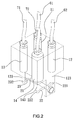
- the auxiliary device 1 of a hydraulic brake assembly for two-wheel vehicles of the present invention is connected to the left brake lever hose 61, the right brake lever hose 62, the front wheel brake hose 71 and the rear wheel brake hose 72 of the two-wheel vehicle.
- the auxiliary device 1 comprises a body 10 and a transmission device 20.
- the body 10 is a rectangular body and has four cylinders 11, 12, 13, 14 located between the top and the bottom thereof.
- the four cylinders 11, 12, 13, 14 are respectively connected to the left brake lever hose 61, the right brake lever hose 62, the front wheel brake hose 71 and the rear wheel brake hose 72.
- Each of the four cylinders 11, 12, 13, 14 has a movable unit 111/121/131/141 which has a first end located in the cylinder 11/12/13/14 corresponding thereto, and a second end protruding beyond the first end of the cylinder 11/12/13/14 corresponding thereto.
- Each of the movable units 111, 121, 131, 141 is movable relative to the cylinder 11/12/13/14 corresponding thereto axially.
- the movable unit 111/121/131/141 has a piston 112/122/132/142 and a piston rod 113/123/133/143.
- the piston 112/122/132/142 is movably located in the cylinder 11/12/13/14 corresponding thereto, and the piston rod 113/123/133/143 has a first end connected to the piston 112/122/132/142, and a second end protruding beyond the first end of the cylinder 11/12/13/14.
- the transmission device 20 is connected to the connection portion 15 on the bottom of the body 10, and comprises a positioning rod 21, a first link 22 and a second link 23.
- the positioning rod 21 extends through the connection portion 15 and is rotatable along the axis thereof.
- the first and second links 22, 23 respectively extend through the positioning rod 21, and are rotatable with the positioning rod 21.
- a driving end 221 and a passive end 222 are connected to the two ends of the first link 22, and are respectively located on the two movement tracks of the two piston rods 123, 143 connected to the two cylinders 12, 14 which are connected to the right brake lever hose 62 and the rear wheel brake hose 72.
- the other driving end 231 and the other passive end 232 are connected to the two ends of the second link 23, and are respectively located on the two movement tracks of the two piston rods 113, 133 connected to the two cylinders 11, 13 which are connected to the left brake lever hose 61 and the front wheel brake hose 71.
- the first link 22 is activated by the positioning rod 21, and is rotated along with the second link 23 so that the passive end 222 pushes the piston rod 143.
- the two piston rods 133, 143 move the pistons 132, 142 to drive the front wheel brake unit and the rear wheel brake unit via the front and rear wheel brake hoses 71, 72.
- the first link 22 rotates the positioning rod 21 and drives the second link 23 so as to drive the front wheel brake unit and the rear wheel brake unit via the front and rear wheel brake hoses 71, 72.
- the present invention is easily operated and can activate the front wheel brake unit and the rear wheel brake unit by either pulling the left or right brake lever.
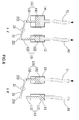
- the transmission device 20 is replaced by the transmission device 30 which has a positioning rod 31, a first link 32 and a second link 33.
- the central portion of the positioning rod 31 is connected to the connection portion 16 located at the bottom of the body 10 and is secured by a positioning shaft 161, so that the positioning rod 31 is rotatable about the positioning shaft 161.
- the first and second links 32, 33 are respectively connected to the two ends of the positioning rod 31.
- the two driving ends 321, 322 are located on two ends of the first link 32 and located on the movement tracks of the two protruding piston rods 113, 123.
- the two passive ends 331, 332 are located on two ends of the second link 33, and located on the movement tracks of the two protruding piston rods 133, 143.
- the two passive ends 331, 332 simultaneously push the piston rods 133, 143 and the two pistons 132, 142 so as to drive the front wheel brake unit and the rear wheel brake unit via the front and rear wheel brake hoses 71, 72.
- the piston 122 and the piston rod 123 of the cylinder 12 are driven via the hydraulic power from the right brake lever hose 62.
- the first link 32 is moved downward and the second link 33 on the other end of the positioning rod 31 is moved upward.
- the two passive ends 331, 332 simultaneously push the piston rods 133, 143 and the two pistons 132, 142 so as to drive the front wheel brake unit and the rear wheel brake unit via the front and rear wheel brake hoses 71, 72.
- the left and right brake lever hoses 61, 62 and the front and rear wheel brake hoses 71, 72 are connected to the same side of the body 10, by the cooperation of the transmission devices 20, 30 on the other side of the body 10, using the leverage principle, when the driving ends 221(231), 321 (322) is moved downward, the two passive ends 222, 232, 331, 332 are moved upward by the positioning rods 21, 31 to achieve the safe braking action.
- the four hoses are connected to the same side of the body 10 and this is difficult when installed to the vehicle.
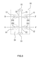
- the applicant further provides an improved arrangement as shown in Figs. 11 to 15 , the left and right brake lever hoses 61, 62 and the front and rear wheel brake hoses 71, 72 are respectively connected to the two opposite sides of the body 50, which is more convenient when in use.
- the third embodiment of the auxiliary device 1 of the present invention comprises a body 50 and a transmission device 40, wherein the body 50 is a rectangular body and has four cylinders 51, 52, 53, 54 located between the top and the bottom thereof.
- the two cylinders 51, 52 on the top of the body 50 are connected to the left and right brake lever hoses 61, 62, and the other two cylinders 53, 54 on the bottom of the body 50 are connected to the front and rear wheel brake hoses 71, 72.
- Each of the cylinders 51, 52, 53, 54 has a movable unit 511/521/531/541 which has a piston 512/522/532/542 and a piston rod 513/523/533/543.
- the piston 512/522/532/542 is movably located in the cylinder 51/52/53/54 corresponding thereto.
- the piston rod 513/523/533/543 is connected to the piston 512/522/532/542 correspondingly and protrudes beyond the cylinder 51/52/53/54 corresponding thereto and located in opposite to the hose.
- the piston rods 513, 523 of the cylinders 51, 52 that are connected to the left and right brake lever hoses 61, 62, extend beyond the bottom of the body 50.
- the piston rods 533, 543 of the cylinders 53, 54 that are connected to the front and rear wheel brake hoses 71, 72, extend beyond the top of the body 50.
- the transmission device 40 of the embodiment has a positioning rod 41, a first link 42 and a second link 43.
- the positioning rod 41 extends through the body 50 and the two ends of the positioning rod 41 respectively extend beyond the top and bottom of the body 50.
- the two ends of the positioning rod 41 are respectively connected to the first and second links 42, 43.
- the two driving ends 421, 422 are located on the two ends of the first link 42 and located on the movement tracks of the two protruding piston rods 513, 523.
- the two passive ends 431, 432 are located on the two ends of the second link 43, and located on the movement tracks of the two protruding piston rods 533, 543.
- the two passive ends 431, 432 simultaneously push the piston rods 533, 543 and the two pistons 532, 542 so as to drive the front wheel brake unit and the rear wheel brake unit via the front and rear wheel brake hoses 71, 72.
- the piston 522 and the piston rod 523 of the cylinder 52 are driven via the hydraulic power from the right brake lever hose 62.
- the first link 42 is moved downward, and the positioning rod 41 and the second link 43 are moved downward.
- the two passive ends 431, 432 simultaneously push the piston rods 533, 543 and the two pistons 532, 542 so as to drive the front wheel brake unit and the rear wheel brake unit via the front and rear wheel brake hoses 71, 72.
- the driving ends 221, 231, 321, 322, 421, 422 are located in the cylinders 12, 11, 11, 12, 51, 52 which has limited amount or even no hydraulic oil when the brake lever is not pulled.
- the hydraulic oil is full to have the best status for the braking actions.
- the front and wheel are braked by either pulling the left brake lever or the right brake lever.
- the front wheel brake unit and the rear wheel brake unit are simultaneously activated by pulling either the left brake lever or the right break lever.
- the front wheel brake unit and the rear wheel brake unit are simultaneously activated by pulling either the left brake lever or the right break lever.
- the front wheel brake unit and the rear wheel brake unit preferably, the front wheel is braked right after the rear wheel is braked.
- the braking force applied to the rear wheel is larger than that to the front wheel.
- the diameters of the cylinders 14, 54 connected to the rear wheel brake hose 72 are larger than those of the diameters of the cylinders 13, 53 connected to the front wheel brake hose 71, this is helpful for the control to the vehicle when the rider brakes the vehicle.
Landscapes
- Engineering & Computer Science (AREA)
- Mechanical Engineering (AREA)
- Physics & Mathematics (AREA)
- Fluid Mechanics (AREA)
- Transportation (AREA)
- Transmission Of Braking Force In Braking Systems (AREA)
Priority Applications (1)
| Application Number | Priority Date | Filing Date | Title |
|---|---|---|---|
| EP14151492.7A EP2896554B1 (de) | 2014-01-16 | 2014-01-16 | Zusatvorrichtung für eine hydraulische Bremsanordnung |
Applications Claiming Priority (1)
| Application Number | Priority Date | Filing Date | Title |
|---|---|---|---|
| EP14151492.7A EP2896554B1 (de) | 2014-01-16 | 2014-01-16 | Zusatvorrichtung für eine hydraulische Bremsanordnung |
Publications (2)
| Publication Number | Publication Date |
|---|---|
| EP2896554A1 true EP2896554A1 (de) | 2015-07-22 |
| EP2896554B1 EP2896554B1 (de) | 2017-03-15 |
Family
ID=49920300
Family Applications (1)
| Application Number | Title | Priority Date | Filing Date |
|---|---|---|---|
| EP14151492.7A Not-in-force EP2896554B1 (de) | 2014-01-16 | 2014-01-16 | Zusatvorrichtung für eine hydraulische Bremsanordnung |
Country Status (1)
| Country | Link |
|---|---|
| EP (1) | EP2896554B1 (de) |
Cited By (1)
| Publication number | Priority date | Publication date | Assignee | Title |
|---|---|---|---|---|
| WO2017211347A1 (de) * | 2016-06-08 | 2017-12-14 | Schaeffler Technologies AG & Co. KG | Bremsanlage für ein fahrzeug sowie fahrzeug mit der bremsanlage |
Citations (3)
| Publication number | Priority date | Publication date | Assignee | Title |
|---|---|---|---|---|
| JP2000280886A (ja) * | 1999-03-31 | 2000-10-10 | Nissin Kogyo Co Ltd | 液圧式バーハンドル車両用ブレーキ装置 |
| US20030201667A1 (en) * | 2002-04-29 | 2003-10-30 | Chih-Chen Juan | Hydraulic balanced braking system |
| EP2639123A1 (de) * | 2012-03-16 | 2013-09-18 | Ansure, Inc. | Bremshilfsvorrichtung |
-
2014
- 2014-01-16 EP EP14151492.7A patent/EP2896554B1/de not_active Not-in-force
Patent Citations (3)
| Publication number | Priority date | Publication date | Assignee | Title |
|---|---|---|---|---|
| JP2000280886A (ja) * | 1999-03-31 | 2000-10-10 | Nissin Kogyo Co Ltd | 液圧式バーハンドル車両用ブレーキ装置 |
| US20030201667A1 (en) * | 2002-04-29 | 2003-10-30 | Chih-Chen Juan | Hydraulic balanced braking system |
| EP2639123A1 (de) * | 2012-03-16 | 2013-09-18 | Ansure, Inc. | Bremshilfsvorrichtung |
Cited By (1)
| Publication number | Priority date | Publication date | Assignee | Title |
|---|---|---|---|---|
| WO2017211347A1 (de) * | 2016-06-08 | 2017-12-14 | Schaeffler Technologies AG & Co. KG | Bremsanlage für ein fahrzeug sowie fahrzeug mit der bremsanlage |
Also Published As
| Publication number | Publication date |
|---|---|
| EP2896554B1 (de) | 2017-03-15 |
Similar Documents
| Publication | Publication Date | Title |
|---|---|---|
| CN107645998B (zh) | 用于车辆的组合制动装置 | |
| EP3495254B1 (de) | Hydraulische zeitdifferenzbasierte bremsvorrichtung | |
| RU2712208C1 (ru) | Система безопасного торможения с двойным сцеплением | |
| ITBO20080651A1 (it) | Impianto frenante di un veicolo atto a comandare una frenata rigenerativa | |
| DE102018125566A1 (de) | Bremsvorrichtung und bremssystem | |
| CN201800698U (zh) | 一种全地形车的行车和驻车制动装置 | |
| TWI769332B (zh) | 煞車裝置及煞車系統 | |
| US9227693B2 (en) | Auxiliary device for hydraulic brake assembly | |
| EP2896554A1 (de) | Zusatvorrichtung für eine hydraulische Bremsanordnung | |
| TWI638742B (zh) | 用於自行車車把的一體式驅動器 | |
| JP6300894B2 (ja) | 油圧式時間差ブレーキ装置 | |
| CN103303295A (zh) | 车辆用制动装置 | |
| TWI637871B (zh) | 液壓煞車系統及其控制裝置 | |
| CN101337545A (zh) | 自行车和机动车的防抱死和防滑机械转矩刹车系统及方法 | |
| US20150075920A1 (en) | Brake Release System | |
| CN105952820B (zh) | 具有制动手动解除机构的压路机液压马达 | |
| CN104787694A (zh) | 液压刹车释放装置 | |
| CN204915637U (zh) | 一种采用液压控制的驻车制动机构 | |
| JP2004217211A (ja) | 車両用ディスクブレーキ | |
| US3692147A (en) | Brake system using vehicle's own kinetic energy to control the brake and the device thereof | |
| CN203864902U (zh) | 组合式手刹制动装置 | |
| TWI489045B (zh) | Hydraulic brake assist device | |
| CN200995674Y (zh) | 拖拉机四轮制动控制装置 | |
| JP3121856U (ja) | 操作力補助装置 | |
| CN210949623U (zh) | 双活塞刹车力放大器 |
Legal Events
| Date | Code | Title | Description |
|---|---|---|---|
| PUAI | Public reference made under article 153(3) epc to a published international application that has entered the european phase |
Free format text: ORIGINAL CODE: 0009012 |
|
| 17P | Request for examination filed |
Effective date: 20140116 |
|
| AK | Designated contracting states |
Kind code of ref document: A1 Designated state(s): AL AT BE BG CH CY CZ DE DK EE ES FI FR GB GR HR HU IE IS IT LI LT LU LV MC MK MT NL NO PL PT RO RS SE SI SK SM TR |
|
| AX | Request for extension of the european patent |
Extension state: BA ME |
|
| 17P | Request for examination filed |
Effective date: 20160122 |
|
| RBV | Designated contracting states (corrected) |
Designated state(s): AL AT BE BG CH CY CZ DE DK EE ES FI FR GB GR HR HU IE IS IT LI LT LU LV MC MK MT NL NO PL PT RO RS SE SI SK SM TR |
|
| GRAP | Despatch of communication of intention to grant a patent |
Free format text: ORIGINAL CODE: EPIDOSNIGR1 |
|
| RIC1 | Information provided on ipc code assigned before grant |
Ipc: B62L 3/08 20060101AFI20160809BHEP Ipc: B60T 8/26 20060101ALN20160809BHEP |
|
| INTG | Intention to grant announced |
Effective date: 20160902 |
|
| RIN1 | Information on inventor provided before grant (corrected) |
Inventor name: TSENG, TON-RONG |
|
| GRAS | Grant fee paid |
Free format text: ORIGINAL CODE: EPIDOSNIGR3 |
|
| GRAA | (expected) grant |
Free format text: ORIGINAL CODE: 0009210 |
|
| AK | Designated contracting states |
Kind code of ref document: B1 Designated state(s): AL AT BE BG CH CY CZ DE DK EE ES FI FR GB GR HR HU IE IS IT LI LT LU LV MC MK MT NL NO PL PT RO RS SE SI SK SM TR |
|
| REG | Reference to a national code |
Ref country code: CH Ref legal event code: EP Ref country code: GB Ref legal event code: FG4D |
|
| REG | Reference to a national code |
Ref country code: IE Ref legal event code: FG4D |
|
| REG | Reference to a national code |
Ref country code: AT Ref legal event code: REF Ref document number: 875230 Country of ref document: AT Kind code of ref document: T Effective date: 20170415 |
|
| REG | Reference to a national code |
Ref country code: DE Ref legal event code: R096 Ref document number: 602014007490 Country of ref document: DE |
|
| REG | Reference to a national code |
Ref country code: NL Ref legal event code: FP |
|
| REG | Reference to a national code |
Ref country code: LT Ref legal event code: MG4D |
|
| PG25 | Lapsed in a contracting state [announced via postgrant information from national office to epo] |
Ref country code: FI Free format text: LAPSE BECAUSE OF FAILURE TO SUBMIT A TRANSLATION OF THE DESCRIPTION OR TO PAY THE FEE WITHIN THE PRESCRIBED TIME-LIMIT Effective date: 20170315 Ref country code: HR Free format text: LAPSE BECAUSE OF FAILURE TO SUBMIT A TRANSLATION OF THE DESCRIPTION OR TO PAY THE FEE WITHIN THE PRESCRIBED TIME-LIMIT Effective date: 20170315 Ref country code: GR Free format text: LAPSE BECAUSE OF FAILURE TO SUBMIT A TRANSLATION OF THE DESCRIPTION OR TO PAY THE FEE WITHIN THE PRESCRIBED TIME-LIMIT Effective date: 20170616 Ref country code: LT Free format text: LAPSE BECAUSE OF FAILURE TO SUBMIT A TRANSLATION OF THE DESCRIPTION OR TO PAY THE FEE WITHIN THE PRESCRIBED TIME-LIMIT Effective date: 20170315 Ref country code: NO Free format text: LAPSE BECAUSE OF FAILURE TO SUBMIT A TRANSLATION OF THE DESCRIPTION OR TO PAY THE FEE WITHIN THE PRESCRIBED TIME-LIMIT Effective date: 20170615 |
|
| REG | Reference to a national code |
Ref country code: AT Ref legal event code: MK05 Ref document number: 875230 Country of ref document: AT Kind code of ref document: T Effective date: 20170315 |
|
| PG25 | Lapsed in a contracting state [announced via postgrant information from national office to epo] |
Ref country code: RS Free format text: LAPSE BECAUSE OF FAILURE TO SUBMIT A TRANSLATION OF THE DESCRIPTION OR TO PAY THE FEE WITHIN THE PRESCRIBED TIME-LIMIT Effective date: 20170315 Ref country code: LV Free format text: LAPSE BECAUSE OF FAILURE TO SUBMIT A TRANSLATION OF THE DESCRIPTION OR TO PAY THE FEE WITHIN THE PRESCRIBED TIME-LIMIT Effective date: 20170315 Ref country code: BG Free format text: LAPSE BECAUSE OF FAILURE TO SUBMIT A TRANSLATION OF THE DESCRIPTION OR TO PAY THE FEE WITHIN THE PRESCRIBED TIME-LIMIT Effective date: 20170615 Ref country code: SE Free format text: LAPSE BECAUSE OF FAILURE TO SUBMIT A TRANSLATION OF THE DESCRIPTION OR TO PAY THE FEE WITHIN THE PRESCRIBED TIME-LIMIT Effective date: 20170315 |
|
| PG25 | Lapsed in a contracting state [announced via postgrant information from national office to epo] |
Ref country code: AT Free format text: LAPSE BECAUSE OF FAILURE TO SUBMIT A TRANSLATION OF THE DESCRIPTION OR TO PAY THE FEE WITHIN THE PRESCRIBED TIME-LIMIT Effective date: 20170315 Ref country code: CZ Free format text: LAPSE BECAUSE OF FAILURE TO SUBMIT A TRANSLATION OF THE DESCRIPTION OR TO PAY THE FEE WITHIN THE PRESCRIBED TIME-LIMIT Effective date: 20170315 Ref country code: ES Free format text: LAPSE BECAUSE OF FAILURE TO SUBMIT A TRANSLATION OF THE DESCRIPTION OR TO PAY THE FEE WITHIN THE PRESCRIBED TIME-LIMIT Effective date: 20170315 Ref country code: RO Free format text: LAPSE BECAUSE OF FAILURE TO SUBMIT A TRANSLATION OF THE DESCRIPTION OR TO PAY THE FEE WITHIN THE PRESCRIBED TIME-LIMIT Effective date: 20170315 Ref country code: SK Free format text: LAPSE BECAUSE OF FAILURE TO SUBMIT A TRANSLATION OF THE DESCRIPTION OR TO PAY THE FEE WITHIN THE PRESCRIBED TIME-LIMIT Effective date: 20170315 Ref country code: EE Free format text: LAPSE BECAUSE OF FAILURE TO SUBMIT A TRANSLATION OF THE DESCRIPTION OR TO PAY THE FEE WITHIN THE PRESCRIBED TIME-LIMIT Effective date: 20170315 |
|
| PG25 | Lapsed in a contracting state [announced via postgrant information from national office to epo] |
Ref country code: PL Free format text: LAPSE BECAUSE OF FAILURE TO SUBMIT A TRANSLATION OF THE DESCRIPTION OR TO PAY THE FEE WITHIN THE PRESCRIBED TIME-LIMIT Effective date: 20170315 Ref country code: PT Free format text: LAPSE BECAUSE OF FAILURE TO SUBMIT A TRANSLATION OF THE DESCRIPTION OR TO PAY THE FEE WITHIN THE PRESCRIBED TIME-LIMIT Effective date: 20170717 Ref country code: IS Free format text: LAPSE BECAUSE OF FAILURE TO SUBMIT A TRANSLATION OF THE DESCRIPTION OR TO PAY THE FEE WITHIN THE PRESCRIBED TIME-LIMIT Effective date: 20170715 Ref country code: SM Free format text: LAPSE BECAUSE OF FAILURE TO SUBMIT A TRANSLATION OF THE DESCRIPTION OR TO PAY THE FEE WITHIN THE PRESCRIBED TIME-LIMIT Effective date: 20170315 |
|
| REG | Reference to a national code |
Ref country code: DE Ref legal event code: R097 Ref document number: 602014007490 Country of ref document: DE |
|
| PLBE | No opposition filed within time limit |
Free format text: ORIGINAL CODE: 0009261 |
|
| STAA | Information on the status of an ep patent application or granted ep patent |
Free format text: STATUS: NO OPPOSITION FILED WITHIN TIME LIMIT |
|
| REG | Reference to a national code |
Ref country code: FR Ref legal event code: PLFP Year of fee payment: 5 |
|
| PG25 | Lapsed in a contracting state [announced via postgrant information from national office to epo] |
Ref country code: DK Free format text: LAPSE BECAUSE OF FAILURE TO SUBMIT A TRANSLATION OF THE DESCRIPTION OR TO PAY THE FEE WITHIN THE PRESCRIBED TIME-LIMIT Effective date: 20170315 |
|
| 26N | No opposition filed |
Effective date: 20171218 |
|
| PG25 | Lapsed in a contracting state [announced via postgrant information from national office to epo] |
Ref country code: IT Free format text: LAPSE BECAUSE OF FAILURE TO SUBMIT A TRANSLATION OF THE DESCRIPTION OR TO PAY THE FEE WITHIN THE PRESCRIBED TIME-LIMIT Effective date: 20170315 Ref country code: SI Free format text: LAPSE BECAUSE OF FAILURE TO SUBMIT A TRANSLATION OF THE DESCRIPTION OR TO PAY THE FEE WITHIN THE PRESCRIBED TIME-LIMIT Effective date: 20170315 |
|
| PGFP | Annual fee paid to national office [announced via postgrant information from national office to epo] |
Ref country code: NL Payment date: 20180116 Year of fee payment: 5 |
|
| PGFP | Annual fee paid to national office [announced via postgrant information from national office to epo] |
Ref country code: GB Payment date: 20180108 Year of fee payment: 5 |
|
| PGFP | Annual fee paid to national office [announced via postgrant information from national office to epo] |
Ref country code: FR Payment date: 20180130 Year of fee payment: 5 |
|
| REG | Reference to a national code |
Ref country code: CH Ref legal event code: PL |
|
| PG25 | Lapsed in a contracting state [announced via postgrant information from national office to epo] |
Ref country code: LU Free format text: LAPSE BECAUSE OF NON-PAYMENT OF DUE FEES Effective date: 20180116 |
|
| REG | Reference to a national code |
Ref country code: IE Ref legal event code: MM4A |
|
| REG | Reference to a national code |
Ref country code: BE Ref legal event code: MM Effective date: 20180131 |
|
| PG25 | Lapsed in a contracting state [announced via postgrant information from national office to epo] |
Ref country code: BE Free format text: LAPSE BECAUSE OF NON-PAYMENT OF DUE FEES Effective date: 20180131 Ref country code: CH Free format text: LAPSE BECAUSE OF NON-PAYMENT OF DUE FEES Effective date: 20180131 Ref country code: LI Free format text: LAPSE BECAUSE OF NON-PAYMENT OF DUE FEES Effective date: 20180131 |
|
| PG25 | Lapsed in a contracting state [announced via postgrant information from national office to epo] |
Ref country code: IE Free format text: LAPSE BECAUSE OF NON-PAYMENT OF DUE FEES Effective date: 20180116 |
|
| PGFP | Annual fee paid to national office [announced via postgrant information from national office to epo] |
Ref country code: DE Payment date: 20190125 Year of fee payment: 6 |
|
| PG25 | Lapsed in a contracting state [announced via postgrant information from national office to epo] |
Ref country code: MC Free format text: LAPSE BECAUSE OF FAILURE TO SUBMIT A TRANSLATION OF THE DESCRIPTION OR TO PAY THE FEE WITHIN THE PRESCRIBED TIME-LIMIT Effective date: 20170315 |
|
| REG | Reference to a national code |
Ref country code: NL Ref legal event code: MM Effective date: 20190201 |
|
| GBPC | Gb: european patent ceased through non-payment of renewal fee |
Effective date: 20190116 |
|
| PG25 | Lapsed in a contracting state [announced via postgrant information from national office to epo] |
Ref country code: FR Free format text: LAPSE BECAUSE OF NON-PAYMENT OF DUE FEES Effective date: 20190131 Ref country code: NL Free format text: LAPSE BECAUSE OF NON-PAYMENT OF DUE FEES Effective date: 20190201 |
|
| PG25 | Lapsed in a contracting state [announced via postgrant information from national office to epo] |
Ref country code: GB Free format text: LAPSE BECAUSE OF NON-PAYMENT OF DUE FEES Effective date: 20190116 |
|
| PG25 | Lapsed in a contracting state [announced via postgrant information from national office to epo] |
Ref country code: MT Free format text: LAPSE BECAUSE OF NON-PAYMENT OF DUE FEES Effective date: 20180116 |
|
| PG25 | Lapsed in a contracting state [announced via postgrant information from national office to epo] |
Ref country code: TR Free format text: LAPSE BECAUSE OF FAILURE TO SUBMIT A TRANSLATION OF THE DESCRIPTION OR TO PAY THE FEE WITHIN THE PRESCRIBED TIME-LIMIT Effective date: 20170315 |
|
| PG25 | Lapsed in a contracting state [announced via postgrant information from national office to epo] |
Ref country code: HU Free format text: LAPSE BECAUSE OF FAILURE TO SUBMIT A TRANSLATION OF THE DESCRIPTION OR TO PAY THE FEE WITHIN THE PRESCRIBED TIME-LIMIT; INVALID AB INITIO Effective date: 20140116 Ref country code: MK Free format text: LAPSE BECAUSE OF NON-PAYMENT OF DUE FEES Effective date: 20170315 Ref country code: CY Free format text: LAPSE BECAUSE OF FAILURE TO SUBMIT A TRANSLATION OF THE DESCRIPTION OR TO PAY THE FEE WITHIN THE PRESCRIBED TIME-LIMIT Effective date: 20170315 |
|
| PG25 | Lapsed in a contracting state [announced via postgrant information from national office to epo] |
Ref country code: AL Free format text: LAPSE BECAUSE OF FAILURE TO SUBMIT A TRANSLATION OF THE DESCRIPTION OR TO PAY THE FEE WITHIN THE PRESCRIBED TIME-LIMIT Effective date: 20170315 |
|
| REG | Reference to a national code |
Ref country code: DE Ref legal event code: R119 Ref document number: 602014007490 Country of ref document: DE |
|
| PG25 | Lapsed in a contracting state [announced via postgrant information from national office to epo] |
Ref country code: DE Free format text: LAPSE BECAUSE OF NON-PAYMENT OF DUE FEES Effective date: 20200801 |