EP2896533A1 - Semiconductor device and driving apparatus - Google Patents
Semiconductor device and driving apparatus Download PDFInfo
- Publication number
- EP2896533A1 EP2896533A1 EP15150973.4A EP15150973A EP2896533A1 EP 2896533 A1 EP2896533 A1 EP 2896533A1 EP 15150973 A EP15150973 A EP 15150973A EP 2896533 A1 EP2896533 A1 EP 2896533A1
- Authority
- EP
- European Patent Office
- Prior art keywords
- analog
- digital
- angle data
- converter
- data
- Prior art date
- Legal status (The legal status is an assumption and is not a legal conclusion. Google has not performed a legal analysis and makes no representation as to the accuracy of the status listed.)
- Withdrawn
Links
Images


Classifications
-
- H—ELECTRICITY
- H02—GENERATION; CONVERSION OR DISTRIBUTION OF ELECTRIC POWER
- H02P—CONTROL OR REGULATION OF ELECTRIC MOTORS, ELECTRIC GENERATORS OR DYNAMO-ELECTRIC CONVERTERS; CONTROLLING TRANSFORMERS, REACTORS OR CHOKE COILS
- H02P6/00—Arrangements for controlling synchronous motors or other dynamo-electric motors using electronic commutation dependent on the rotor position; Electronic commutators therefor
- H02P6/08—Arrangements for controlling the speed or torque of a single motor
-
- H—ELECTRICITY
- H02—GENERATION; CONVERSION OR DISTRIBUTION OF ELECTRIC POWER
- H02P—CONTROL OR REGULATION OF ELECTRIC MOTORS, ELECTRIC GENERATORS OR DYNAMO-ELECTRIC CONVERTERS; CONTROLLING TRANSFORMERS, REACTORS OR CHOKE COILS
- H02P6/00—Arrangements for controlling synchronous motors or other dynamo-electric motors using electronic commutation dependent on the rotor position; Electronic commutators therefor
- H02P6/14—Electronic commutators
- H02P6/16—Circuit arrangements for detecting position
-
- B—PERFORMING OPERATIONS; TRANSPORTING
- B60—VEHICLES IN GENERAL
- B60L—PROPULSION OF ELECTRICALLY-PROPELLED VEHICLES; SUPPLYING ELECTRIC POWER FOR AUXILIARY EQUIPMENT OF ELECTRICALLY-PROPELLED VEHICLES; ELECTRODYNAMIC BRAKE SYSTEMS FOR VEHICLES IN GENERAL; MAGNETIC SUSPENSION OR LEVITATION FOR VEHICLES; MONITORING OPERATING VARIABLES OF ELECTRICALLY-PROPELLED VEHICLES; ELECTRIC SAFETY DEVICES FOR ELECTRICALLY-PROPELLED VEHICLES
- B60L3/00—Electric devices on electrically-propelled vehicles for safety purposes; Monitoring operating variables, e.g. speed, deceleration or energy consumption
- B60L3/0023—Detecting, eliminating, remedying or compensating for drive train abnormalities, e.g. failures within the drive train
- B60L3/0084—Detecting, eliminating, remedying or compensating for drive train abnormalities, e.g. failures within the drive train relating to control modules
-
- B—PERFORMING OPERATIONS; TRANSPORTING
- B60—VEHICLES IN GENERAL
- B60L—PROPULSION OF ELECTRICALLY-PROPELLED VEHICLES; SUPPLYING ELECTRIC POWER FOR AUXILIARY EQUIPMENT OF ELECTRICALLY-PROPELLED VEHICLES; ELECTRODYNAMIC BRAKE SYSTEMS FOR VEHICLES IN GENERAL; MAGNETIC SUSPENSION OR LEVITATION FOR VEHICLES; MONITORING OPERATING VARIABLES OF ELECTRICALLY-PROPELLED VEHICLES; ELECTRIC SAFETY DEVICES FOR ELECTRICALLY-PROPELLED VEHICLES
- B60L3/00—Electric devices on electrically-propelled vehicles for safety purposes; Monitoring operating variables, e.g. speed, deceleration or energy consumption
- B60L3/0092—Electric devices on electrically-propelled vehicles for safety purposes; Monitoring operating variables, e.g. speed, deceleration or energy consumption with use of redundant elements for safety purposes
-
- H—ELECTRICITY
- H02—GENERATION; CONVERSION OR DISTRIBUTION OF ELECTRIC POWER
- H02P—CONTROL OR REGULATION OF ELECTRIC MOTORS, ELECTRIC GENERATORS OR DYNAMO-ELECTRIC CONVERTERS; CONTROLLING TRANSFORMERS, REACTORS OR CHOKE COILS
- H02P29/00—Arrangements for regulating or controlling electric motors, appropriate for both AC and DC motors
- H02P29/02—Providing protection against overload without automatic interruption of supply
- H02P29/024—Detecting a fault condition, e.g. short circuit, locked rotor, open circuit or loss of load
- H02P29/028—Detecting a fault condition, e.g. short circuit, locked rotor, open circuit or loss of load the motor continuing operation despite the fault condition, e.g. eliminating, compensating for or remedying the fault
-
- H—ELECTRICITY
- H02—GENERATION; CONVERSION OR DISTRIBUTION OF ELECTRIC POWER
- H02P—CONTROL OR REGULATION OF ELECTRIC MOTORS, ELECTRIC GENERATORS OR DYNAMO-ELECTRIC CONVERTERS; CONTROLLING TRANSFORMERS, REACTORS OR CHOKE COILS
- H02P29/00—Arrangements for regulating or controlling electric motors, appropriate for both AC and DC motors
- H02P29/02—Providing protection against overload without automatic interruption of supply
- H02P29/032—Preventing damage to the motor, e.g. setting individual current limits for different drive conditions
-
- G—PHYSICS
- G01—MEASURING; TESTING
- G01D—MEASURING NOT SPECIALLY ADAPTED FOR A SPECIFIC VARIABLE; ARRANGEMENTS FOR MEASURING TWO OR MORE VARIABLES NOT COVERED IN A SINGLE OTHER SUBCLASS; TARIFF METERING APPARATUS; MEASURING OR TESTING NOT OTHERWISE PROVIDED FOR
- G01D5/00—Mechanical means for transferring the output of a sensing member; Means for converting the output of a sensing member to another variable where the form or nature of the sensing member does not constrain the means for converting; Transducers not specially adapted for a specific variable
- G01D5/12—Mechanical means for transferring the output of a sensing member; Means for converting the output of a sensing member to another variable where the form or nature of the sensing member does not constrain the means for converting; Transducers not specially adapted for a specific variable using electric or magnetic means
- G01D5/244—Mechanical means for transferring the output of a sensing member; Means for converting the output of a sensing member to another variable where the form or nature of the sensing member does not constrain the means for converting; Transducers not specially adapted for a specific variable using electric or magnetic means influencing characteristics of pulses or pulse trains; generating pulses or pulse trains
- G01D5/24457—Failure detection
- G01D5/24461—Failure detection by redundancy or plausibility
-
- H—ELECTRICITY
- H02—GENERATION; CONVERSION OR DISTRIBUTION OF ELECTRIC POWER
- H02P—CONTROL OR REGULATION OF ELECTRIC MOTORS, ELECTRIC GENERATORS OR DYNAMO-ELECTRIC CONVERTERS; CONTROLLING TRANSFORMERS, REACTORS OR CHOKE COILS
- H02P31/00—Arrangements for regulating or controlling electric motors not provided for in groups H02P1/00 - H02P5/00, H02P7/00 or H02P21/00 - H02P29/00
-
- Y—GENERAL TAGGING OF NEW TECHNOLOGICAL DEVELOPMENTS; GENERAL TAGGING OF CROSS-SECTIONAL TECHNOLOGIES SPANNING OVER SEVERAL SECTIONS OF THE IPC; TECHNICAL SUBJECTS COVERED BY FORMER USPC CROSS-REFERENCE ART COLLECTIONS [XRACs] AND DIGESTS
- Y02—TECHNOLOGIES OR APPLICATIONS FOR MITIGATION OR ADAPTATION AGAINST CLIMATE CHANGE
- Y02T—CLIMATE CHANGE MITIGATION TECHNOLOGIES RELATED TO TRANSPORTATION
- Y02T10/00—Road transport of goods or passengers
- Y02T10/60—Other road transportation technologies with climate change mitigation effect
- Y02T10/64—Electric machine technologies in electromobility
Definitions
- the present invention relates to a semiconductor device for motor control and a driving apparatus using the same and, more particularly, to a technique for recovering a failure of the motor control function.
- the invention relates to, for example, a technique effectively applied to an in-vehicle product required to maintain control in a temporary emergency manner at the time of a failure such as a hydraulic motor of a brake, a motor of an electric steering, or the like.
- the technique described in the patent literature 1 is premised on a configuration having both a first control unit performing rotation driving control and regenerative control of a synchronous motor for travel driving on the basis of a current signal of a fixed winding of the synchronous motor and a sense output from a rotation angle sensor and a second control unit performing power generation control of a synchronous generator on the basis of a current signal of a fixed winding of the synchronous generator and a sense output from a rotation angle sensor of the synchronous generator, and a failure in one of the units is recovered by the other unit. Since the control performed by the first control unit controlling the synchronous motor and the control performed by the second control unit controlling the synchronous generator are essentially equal, one of them can substitute for a part or all of the other.
- the driving control of the synchronous motor can be maintained in a temporal emergency manner by using a part or all of a control circuit controlling a synchronous generator.
- Patent Literature 1 Japanese Unexamined Patent Application Publication No. 2011-234517
- the technique of the patent literature 1 is premised on usage of both of the control units needing essentially the same controls such as the driving and regenerative control of the motor and the power generation control of the generator. That is, by disposing a microcomputer for motor control and a microcomputer for generator control close to each other, when a failure causing an unusable state is detected in a part of the microcomputer performing the driving control on the synchronous motor, the microcomputer for generator control substitutes for a control related to the failure causing an unusable state in the driving control. Therefore, a failure in a control system of a drive system which is not paired with a generator such as a hydraulic motor of a brake or a drive motor of an electronic steering cannot be recovered by the same method as that for the travel driving system. In short, the technique of the patent literature 1 cannot be applied to a drive system using, as a driving source, a single synchronous motor which is not paired with a synchronous generator.
- a digital angle data converter receiving digital data generated by an analog-to-digital converter and converting it to digital angle data is provided.
- digital rotation angle data used for controlling a drive circuit which generates a motor drive control signal of the synchronous motor is switched from data generated by the analog angle data converter to data generated by converting conversion result data of the analog sense signal by the analog-to-digital converter by the digital angle data converter.
- a semiconductor device (4) includes: a drive circuit (14) generating a motor drive control signal (U, V, W, UB, VB,WB) for a synchronous motor (1); an analog angle data converter (10) receiving an analog sense signal (APFB) which is output from a rotation angle sensor (2) of the synchronous motor and converting the analog sense signal to digital angle data (RDS1) ; an analog-to-digital converter (12) converting an analog signal to a digital signal; a digital angle data converter (11) receiving the digital data generated by the analog-to-digital converter and converting the digital data to digital angle data (RDS2); and a control circuit (13) making the drive circuit generate a motor drive control signal according to a drive instruction on the basis of the digital angle data.
- a drive circuit (14) generating a motor drive control signal (U, V, W, UB, VB,WB) for a synchronous motor (1)
- an analog angle data converter (10) receiving an analog sense signal (APFB) which is output from a rotation angle sensor (2) of the
- control circuit In response to a failure in the analog angle data converter, the control circuit further performs a control of switching digital rotation angle data used for control of the drive circuit from data generated by the analog angle data converter to data generated by converting conversion result data of the analog sense signal obtained by the analog-to-digital converter, by the digital angle data converter.
- the analog angle data converter for detecting the rotation angle of the synchronous motor fails in the system using, as a drive source, the single synchronous motor which is not paired with the synchronous generator, the driving of the synchronous motor can be continued by using the digital angle data converter in a temporal emergency manner.
- a measure against deterioration in conversion precision caused by power supply noise is taken by using a dedicated analog power supply terminal.
- analog power supply terminals for assuring conversion precision which is deteriorated by power supply noise have to be separately provided.
- multiple analog angle data converters are not used.
- an addition circuit is a digital circuit, benefits of reduction in the circuit area and decrease in power brought about by improvement in the process are gained as compared with the case of using an analog circuit, and increase in the circuit scale by addition of the circuit can be minimized.
- the semiconductor device has: an external terminal (P1) which receives the analog sense signal to be supplied to the analog angle data converter from the outside of the semiconductor device; and an external terminal (P2) which receives the analog sense signal to be supplied to the analog-to-digital converter from the outside of the semiconductor device.
- an operation of supplying the analog sense signal to the analog angle data converter or to the digital angle data converter via the analog-to-digital converter can be performed on the outside of the semiconductor device.
- a circuit performing the input selection is provided in the semiconductor device, if the circuit fails, the driving in the temporary emergency manner becomes impossible.
- control circuit performs a (ERrdc) control of notifying the outside of the semiconductor device of a failure of the analog angle data converter.
- switching of the use target from the analog angle data converter to the digital angle data converter can be controlled on the outside of the semiconductor device.
- Analog-to-Digital Converter has Plural Analog/Digital Conversion Channels
- the analog-to-digital converter has a plurality of analog-to-digital conversion channels.
- the analog-to-digital converter is not occupied by analog-to-digital conversion of the analog sense signal.
- the synchronous motor uses a permanent magnet for a rotating magnetic field and has a fixed winding of a three-phase coil for a fixed magnetic field.
- the predetermined analog-to-digital conversion channel receives a current signal (IU, IV, IW) supplied to the fixed winding of the synchronous motor and generates current value data.
- the control circuit makes the drive circuit generate a motor drive control signal according to a drive instruction on the basis of the current value data and the digital angle data.
- torque control and speed control can be performed on the synchronous motor with high precision.
- Control Circuit includes CPU and Operation Program of CPU
- control circuit includes a central processing unit (20) executing an instruction and performing a program process.
- the drive control and switching control by the control circuit can be flexibly realized by program control.
- the semiconductor device is formed as a data processor (4) of one chip.
- the invention can contribute to reduction in size and power consumption of the semiconductor device.
- a driving apparatus (100, 200, 300) has a synchronous motor (1), a rotation angle sensor (2) of the synchronous motor, and a data processor (4).
- the data processor has: a drive circuit (14) generating a motor drive control signal (U, V, W, UB, VB, WB) for the synchronous motor; an analog angle data converter (10) receiving an analog sense signal (APFB) which is output from the rotation angle sensor of the synchronous motor and converting the analog sense signal to digital angle data (RDS1) ; an analog-to-digital converter (12) converting an analog signal to a digital signal; a digital angle data converter (11) receiving the digital data generated by the analog-to-digital converter and converting the digital data to digital angle data (RDS2); and a control circuit (13) making the drive circuit generate a motor drive control signal according to a drive instruction (DRV) on the basis of the digital angle data.
- DDRV drive instruction
- control circuit In response to a failure in the analog angle data converter, the control circuit further performs a control of switching digital rotation angle data used for control of the drive circuit from data generated by the analog angle data converter to data generated by converting conversion result data of the analog sense signal by the analog-to-digital converter, by the digital angle data converter.
- the driving of the synchronous motor can be continued by using the digital angle data converter in a temporal emergency manner.
- the analog angle data converter a measure against deterioration in conversion precision caused by power supply noise is taken by using a dedicated analog power supply terminal.
- analog power supply terminals for assuring conversion precision which is deteriorated by power supply noise have to be separately provided.
- multiple analog angle data converters are not used.
- an addition circuit is a digital circuit, benefits of reduction in the circuit area and decrease in power brought about by improvement in the process are gained more than an analog circuit, and increase in the circuit scale by addition of the circuit can be minimized and it can contribute to reduction in the size of the driving apparatus.
- the driving apparatus further includes: an external terminal (P1) which receives the analog sense signal to be supplied to the analog angle data converter from the outside of the data processor; and an external terminal (P2) which receives the analog sense signal to be supplied to the analog-to-digital converter from the outside of the data processor.
- an operation of supplying the analog sense signal to the analog angle data converter or to the digital angle data converter via the analog-to-digital converter can be performed on the outside of the semiconductor device.
- a circuit performing the input selection is provided in the data processor, if the circuit fails, the driving in the temporary emergency manner becomes impossible.
- control circuit performs a (ERrdc) control of notifying the outside of the data processor of a failure of the analog angle data converter.
- switching of the use target from the analog angle data converter to the digital angle data converter can be controlled on the outside of the data processor.
- the driving apparatus has an analog input selector (5) on the outside of the data processor.
- the analog input selector switches an input destination of an analog sense signal from the rotation angle sensor to the analog-to-digital converter on the basis of notification of a failure of the analog angle data converter.
- the synchronous motor is a dedicated power supply for driving an actuator of a vehicle.
- the driving apparatus is suitable for a drive system driving an actuator such as a brake, an electric steering, or the like in a vehicle.
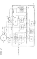
- FIG. 1 illustrates a driving apparatus according to a first embodiment.
- a driving apparatus 100 illustrated in the diagram is applied to, although not limited, control of a drive system of driving an actuator such as a brake, an electric steering, or the like in a vehicle.
- the driving apparatus 100 has, although not limited, a synchronous motor (MT) 1, a rotation angle sensor (RD) 2 of the synchronous motor 1, a power module (PMDL) 3, a data processor (MCU) 4, and a selector (SEL) 5.
- MT synchronous motor
- RD rotation angle sensor
- PMDL power module
- MCU data processor
- SEL selector
- the synchronous motor 1 is, for example, a motor called an IPM (Internal Permanent Magnet) motor of a 3-phase AC drive type using a permanent magnet for a rotating magnetic field, and has a three-phase coil made of a U-phase winding, a V-phase winding, and a W-phase winding for a fixed magnetic field,
- IPM Internal Permanent Magnet
- IU, IV, and IW denote a current signal of the U-phase winding, a current signal of the V-phase winding, and a current signal of the W-phase winding.
- the rotation angle sensor 2 is a sensor for detecting the rotation angle of the motor shaft of the synchronous motor 1 and, although not limited, is configured by a resolver (RD) of a variable reluctance (VR) type for detecting the rotation angle by using an AC magnetic field.
- the rotation angle sensor 2 outputs a signal modulated by a sine wave of the rotation angle of a rotator and a signal modulated by a cosine wave as a resolver output signal (analog sense signal) APFB.
- the power module 3 is configured by a switch circuit functioning as an inverter which converts a direct current signal supplied from a not-illustrated battery to three-phase alternate current signals IU, IV, and IW at the time of rotating the synchronous motor 1 and outputs the signals to the synchronous motor 1, and functioning as a rectifier which converts the three-phase alternate current signals IU, IV, and IW generated by the synchronous motor 1 to a direct current signal at the time of decelerating the synchronous motor 1 and supplies the direct current signal to the battery.
- switch control for the inverter operation of the power module 3 and the switch control for the rectifying operation although not limited, switch control signals U, V, and W and their inverted switch control signals UB, VB, and WB are used.
- the data processor 4 is configured by, although not limited, a microcomputer formed on a single semiconductor substrate made of single-crystal silicon by the CMOS integrated circuit manufacturing technique or the like.
- the data processor 4 performs a drive control of receiving current signals IV and IW of the synchronous motor 1 and the resolver output signal APFB from the rotation angle sensor 2 and rotating the synchronous motor 1 and, in particular, for the converting function of converting the resolver output signal APFB which is supplied to digital angle data, has redundancy which will be described later.
- the data processor 4 has a drive circuit 14, an analog angle data converter (analog RDC) 10, an analog-to-digital converter (ADC) 12, a digital angle data converter (digital RDC) 11, and a control circuit 13 which are representatively illustrated.
- analog RDC analog angle data converter
- ADC analog-to-digital converter
- digital RDC digital angle data converter
- the drive circuit 14 is a circuit for generating a motor drive control signal for the synchronous motor 1 and is made by, for example, a PWM (Pulse Width Modulation) circuit 15 and an output interruption circuit 16.
- the PWM circuit 15 generates the switch control signals U, V, and W and their inverted switch control signals UB, VB, and WB in accordance with the drive control data from the control circuit 13.
- the output interruption circuit 16 is a circuit which is interposed in a path for supplying the switch control signals U, V, and W and their inverted switch control signals UB, VB, and WB to the PMDL 3 and which interrupts supply of the switch control signals U, V, and W and their inverted switch control signals UB, VB, and WB in prompt response to a stop instruction of a drive instruction DRV of the synchronous motor 1 supplied from the outside of the data processor.
- the analog angle data converter (analog RDC) 10 receives the resolver output signal APFB output from the rotation angle sensor 2 of the synchronous motor 1 and converts it to digital angle data RDS1.
- the converted data angle data RDS1 is used in the control circuit 13.
- the analog angle data converter (analog RDC) 10 receives the resolver output signal APFB supplied from an external terminal P1.
- the analog-to-digital converter (ADC) 12 is a circuit for converting an analog signal to a digital signal and has a plurality of analog-to-digital conversion channels. To one analog-to-digital conversion channel, the current signals IV and IW of the synchronous motor 1 are fed back. To another analog-to-digital conversion channel, a signal selected by the selector 5 is supplied from an external terminal P2. The selector 5 selects output of the resolver output signal APFB when an error signal ERrdc is activated (to the enable level), and selects output of a proper analog signal ADI in an active state (disable level) of the error signal ERrdc. Conversion result data of the analog signal ADI is used in the control circuit 13.
- the digital angle data converter (digital RDC) 11 receives digital data DPFB as a conversion result of the resolver output signal APFB by the analog-to-digital converter 12 and converts it to digital angle data RDS2.
- the converted digital angle data RDS2 is used in the control circuit 13.
- the control circuit 13 performs general control on the data processor 4 and performs a control of driving the synchronous motor 1, an alternative control to the digital angle data converter 11, and the like, and controls on the parts in the data processor 4 are performed by a collectively-called control signal CNT.
- the control of driving the synchronous motor is a control of making the PWM circuit 15 in the drive circuit 14 generate the switch control signals U, V, and W and their inverted switch control signals UB, VB, and WB according to a drive instruction on the basis of the digital angle data RDS1 or RDS2 and the feedback data of the current signals IV and IW.
- the control circuit 13 makes the error signal ERrdc inactive and uses the digital angle data RDS1 converted from the resolver output signal APFB by using the analog RDC 10.
- the analog-to-digital conversion result data by the ADC 12 is used by the control circuit 13.
- the digital RDC 11 is made inactive.
- the control of substitution to the digital angle data converter 11 is a control for detection of a conversion failure of the analog RDC 10 and switching to the digital angle data RDS2 responding to the failure detection.
- a method of detecting a conversion failure of the analog RDC 10 by the control circuit 13 for example, it is sufficient to detect a failure by a state that a detection value is largely deviated from a target value or the like in a feedback control using the digital angle data RDS1.
- the control circuit 13 activates the error signal ERrdc toward the outside of the data processor 4 to make the selector 5 select the resolver output signal APFB.
- the resolver output signal APFB supplied from the external terminal P2 of the ADC 12 is converted to the digital data DPFB, and the converted digital data DPFB is converted to the digital angle data RDS2 by the digital angle data converter 11.
- the control of driving the synchronous motor can be continued in a temporal emergency manner.
- the control circuit 13 includes a central processing unit (CPU) 20 executing an instruction and performing a program process, a memory (MRY) 21 including a ROM and a RAM, an external interface circuit (EXIF) 24 receiving a drive instruction DRV and the like, an error control circuit 22, and an internal bus 23.
- the drive circuit 14 To the internal bus 23, the drive circuit 14, the analog RDC 10, the digital RDC 11, and the ADC 12 are connected. Detection of a conversion failure of the analog RDC 10 is performed by the error control circuit 22.
- the error signal ERrdc is supplied as an interrupt request signal to the COU 20. When the signal is activated, an interrupt process for switching to the digital angle data RDS2 responding to the failure detection is started. The details of the process are as described above.
- FIG. 3 illustrates a flow of the driving control of the synchronous motor by the driving apparatus 100.
- the error control circuit 22 determines whether a conversion error occurs in the analog RDC 10 or not (S2).
- the resolver output signal APFB is converted to the digital angle data RDS1 by using the analog RDC 10 and the rotation angle is measured (S3), and the CPU 20 computes the drive control data of the synchronous motor 1 on the basis of the digital angle data RDS1 and the like (S4).
- the switch control signals U, V, and W and their inverted switch control signals UB, VB, and WB of the frequency and phase according to the setting are generated (S5) .
- the synchronous motor 1 is driven.
- step S2 When occurrence of an error is determined in step S2, the error signal ERrdc is activated (S6) and, by the activation, the selector 5 selects the resolver output signal APFB and outputs it (S7).
- the resolver output signal APFB supplied to the ADC 12 via the selector 5 is converted to the digital data DPFB, and the converted digital data DPFB is converted to the digital angle data RDS2 by the digital angle data converter 11 (S8).
- the CPU 20 computes drive control data of the synchronous motor 1 on the basis of the digital angle data RDS2 and the like (S9).
- the switch control signals U, V, and W and their inverted switch control signals UB, VB, and WB of the frequency and phase according to the setting are generated (S10).
- the digital angle data RDS2 is used in place of the digital angle data RDS1, and the drive control of the synchronous motor 1 can be continued in a temporal emergency manner.
- the process is finished (END).
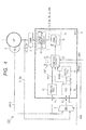
- FIG. 4 illustrates a driving apparatus according to a second embodiment.
- a driving apparatus 200 illustrated in the diagram is different from the first embodiment with respect to the point that in place of the analog signal ADI, the current signals IV and IW fed back from the synchronous motor 1 are supplied to one of input terminals of the selector 5.
- the resolver output signal APFB is selected by the selector 5 in place of the current signals IV and IW fed back. Therefore, the current signals IV and IW which are fed back are not used in the drive control of the motor 1 in a temporal emergency manner using the digital RDC 11.
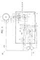
- FIG. 5 illustrates a driving apparatus according to a third embodiment.
- a driving apparatus 300 illustrated in the drawing is an example of the case premised on a configuration in which the current signals IV and IW do not have to be fed back from the synchronous motor 1. Since the other point is similar to the first embodiment, its detailed description will not be repeated.
- the driving apparatus is not limited to an in-vehicle driving apparatus and can be applied to a driving apparatus of industrial equipment.
- the control circuit 13 is not limited to the configuration based on the program control by the CPU but can be also configured by using a hard-wired logic.
- the data processor is not limited to a microcomputer of one chip but may be of multiple chips.
- the memory may be an external memory.
- the conversion error in the analog RDC 10 is an error such that a control allowed in the drive control of the synchronous motor 1 cannot be realized and is not limited to an error that conversion is impossible.
Landscapes
- Engineering & Computer Science (AREA)
- Power Engineering (AREA)
- Life Sciences & Earth Sciences (AREA)
- Sustainable Development (AREA)
- Sustainable Energy (AREA)
- Transportation (AREA)
- Mechanical Engineering (AREA)
- Control Of Motors That Do Not Use Commutators (AREA)
- Control Of Electric Motors In General (AREA)
- Control Of Ac Motors In General (AREA)
Applications Claiming Priority (1)
| Application Number | Priority Date | Filing Date | Title |
|---|---|---|---|
| JP2014007484A JP2015136272A (ja) | 2014-01-20 | 2014-01-20 | 半導体デバイス及び駆動装置 |
Publications (1)
| Publication Number | Publication Date |
|---|---|
| EP2896533A1 true EP2896533A1 (en) | 2015-07-22 |
Family
ID=52339050
Family Applications (1)
| Application Number | Title | Priority Date | Filing Date |
|---|---|---|---|
| EP15150973.4A Withdrawn EP2896533A1 (en) | 2014-01-20 | 2015-01-13 | Semiconductor device and driving apparatus |
Country Status (5)
| Country | Link |
|---|---|
| US (1) | US20150207445A1 (ja) |
| EP (1) | EP2896533A1 (ja) |
| JP (1) | JP2015136272A (ja) |
| KR (1) | KR20150087114A (ja) |
| CN (1) | CN104796046A (ja) |
Families Citing this family (5)
| Publication number | Priority date | Publication date | Assignee | Title |
|---|---|---|---|---|
| JPWO2018100597A1 (ja) * | 2016-11-29 | 2019-06-24 | サンケン電気株式会社 | Ad変換装置 |
| US10830591B2 (en) | 2018-03-23 | 2020-11-10 | The Boeing Company | System and method for dual speed resolver |
| US10911061B2 (en) * | 2018-03-23 | 2021-02-02 | The Boeing Company | System and method for demodulation of resolver outputs |
| US10913550B2 (en) | 2018-03-23 | 2021-02-09 | The Boeing Company | System and method for position and speed feedback control |
| CN113359026A (zh) * | 2020-03-06 | 2021-09-07 | 比亚迪股份有限公司 | 电机参数诊断装置及系统 |
Citations (4)
| Publication number | Priority date | Publication date | Assignee | Title |
|---|---|---|---|---|
| EP1684051A1 (en) * | 2003-11-04 | 2006-07-26 | NSK Ltd. | Controller for electric power-steering apparatus |
| JP2011234517A (ja) | 2010-04-28 | 2011-11-17 | Renesas Electronics Corp | 動力駆動制御装置および動力装置 |
| EP2413495A1 (en) * | 2009-03-27 | 2012-02-01 | Renesas Electronics Corporation | Semiconductor integrated circuit device |
| JP2013186105A (ja) * | 2012-03-12 | 2013-09-19 | Renesas Electronics Corp | 信号検出システム、レゾルバ信号処理システム及び半導体集積回路 |
Family Cites Families (8)
| Publication number | Priority date | Publication date | Assignee | Title |
|---|---|---|---|---|
| KR0130537B1 (ko) * | 1994-05-31 | 1998-04-09 | 이대원 | 토크리플을 최소화시킨 브러쉬없는 직류전동기 제어시스템 |
| JP4067949B2 (ja) * | 2002-12-03 | 2008-03-26 | サンデン株式会社 | モータ制御装置 |
| GB0324785D0 (en) * | 2003-10-24 | 2003-11-26 | Electronica Products Ltd | Magnetic gearing of permanent magnet brushless motors |
| US7348743B1 (en) * | 2007-10-30 | 2008-03-25 | International Business Machines Corporation | Apparatus to remove foreign particles from heat transfer surfaces of heat sinks |
| GB2462446A (en) * | 2008-08-07 | 2010-02-10 | Technelec Ltd | Micro-steping reluctance motor |
| JP2011040899A (ja) * | 2009-08-07 | 2011-02-24 | Renesas Electronics Corp | アナログ・デジタル変換回路、半導体装置、及び電動パワーステアリング制御ユニット |
| JP5582954B2 (ja) * | 2010-10-12 | 2014-09-03 | ルネサスエレクトロニクス株式会社 | デジタルpll回路、情報再生装置、ディスク再生装置および信号処理方法 |
| US20150311833A1 (en) * | 2014-04-29 | 2015-10-29 | Advanced Power Electronic Solutions, LLC. | General-purpose design of dc-ac inverters in electrified automobile systems |
-
2014
- 2014-01-20 JP JP2014007484A patent/JP2015136272A/ja active Pending
-
2015
- 2015-01-08 US US14/592,874 patent/US20150207445A1/en not_active Abandoned
- 2015-01-13 EP EP15150973.4A patent/EP2896533A1/en not_active Withdrawn
- 2015-01-15 KR KR1020150007488A patent/KR20150087114A/ko not_active Application Discontinuation
- 2015-01-19 CN CN201510026012.6A patent/CN104796046A/zh active Pending
Patent Citations (4)
| Publication number | Priority date | Publication date | Assignee | Title |
|---|---|---|---|---|
| EP1684051A1 (en) * | 2003-11-04 | 2006-07-26 | NSK Ltd. | Controller for electric power-steering apparatus |
| EP2413495A1 (en) * | 2009-03-27 | 2012-02-01 | Renesas Electronics Corporation | Semiconductor integrated circuit device |
| JP2011234517A (ja) | 2010-04-28 | 2011-11-17 | Renesas Electronics Corp | 動力駆動制御装置および動力装置 |
| JP2013186105A (ja) * | 2012-03-12 | 2013-09-19 | Renesas Electronics Corp | 信号検出システム、レゾルバ信号処理システム及び半導体集積回路 |
Also Published As
| Publication number | Publication date |
|---|---|
| JP2015136272A (ja) | 2015-07-27 |
| KR20150087114A (ko) | 2015-07-29 |
| US20150207445A1 (en) | 2015-07-23 |
| CN104796046A (zh) | 2015-07-22 |
Similar Documents
| Publication | Publication Date | Title |
|---|---|---|
| US9647599B2 (en) | Electronic apparatus | |
| JP6169203B1 (ja) | 電動機制御装置および電動機制御方法 | |
| EP2896533A1 (en) | Semiconductor device and driving apparatus | |
| US20170349207A1 (en) | Motor drive device and electric power steering device | |
| JP2014072973A (ja) | 交流電動機の制御装置 | |
| JP2018061400A (ja) | 電流センサ異常診断装置 | |
| JP5732820B2 (ja) | 駆動装置 | |
| JP6652073B2 (ja) | モータ制御装置 | |
| WO2021161794A1 (ja) | 電力変換器の制御回路 | |
| JP5514660B2 (ja) | 負荷制御装置 | |
| CN104779872A (zh) | 同步电动机的控制装置及控制方法 | |
| US10530147B2 (en) | Control device with safety shutdown | |
| CN106961237B (zh) | 电机控制装置以及包括电机控制装置的电动力转向装置 | |
| JP2019087917A (ja) | 制御装置 | |
| JP6488923B2 (ja) | モータ制御装置 | |
| US10444288B2 (en) | Abnormality diagnosing device and abnormality diagnosing method | |
| JP2010178444A (ja) | 回転電機制御システム | |
| JPWO2019102539A1 (ja) | 回転電機制御装置及び電動車両 | |
| US10527676B2 (en) | Abnormality diagnosing device and abnormality diagnosing method | |
| JP2019170057A (ja) | モータ制御装置 | |
| CN114189194A (zh) | 马达控制装置、马达单元以及车辆 | |
| US11018617B2 (en) | Rotation angle detection device and ac rotating machine control device | |
| JP5473071B2 (ja) | 負荷制御装置 | |
| WO2019220780A1 (ja) | 故障診断方法、電力変換装置、モータモジュールおよび電動パワーステアリング装置 | |
| CN115516758A (zh) | 交流旋转电机的控制装置 |
Legal Events
| Date | Code | Title | Description |
|---|---|---|---|
| PUAI | Public reference made under article 153(3) epc to a published international application that has entered the european phase |
Free format text: ORIGINAL CODE: 0009012 |
|
| 17P | Request for examination filed |
Effective date: 20150113 |
|
| AK | Designated contracting states |
Kind code of ref document: A1 Designated state(s): AL AT BE BG CH CY CZ DE DK EE ES FI FR GB GR HR HU IE IS IT LI LT LU LV MC MK MT NL NO PL PT RO RS SE SI SK SM TR |
|
| AX | Request for extension of the european patent |
Extension state: BA ME |
|
| RAP1 | Party data changed (applicant data changed or rights of an application transferred) |
Owner name: RENESAS ELECTRONICS CORPORATION |
|
| 17P | Request for examination filed |
Effective date: 20160122 |
|
| RBV | Designated contracting states (corrected) |
Designated state(s): AL AT BE BG CH CY CZ DE DK EE ES FI FR GB GR HR HU IE IS IT LI LT LU LV MC MK MT NL NO PL PT RO RS SE SI SK SM TR |
|
| RIC1 | Information provided on ipc code assigned before grant |
Ipc: H02P 31/00 20060101ALN20190927BHEP Ipc: H02P 29/032 20160101ALI20190927BHEP Ipc: H02P 6/16 20160101ALI20190927BHEP Ipc: B60L 3/00 20190101AFI20190927BHEP Ipc: G01D 5/244 20060101ALN20190927BHEP |
|
| GRAP | Despatch of communication of intention to grant a patent |
Free format text: ORIGINAL CODE: EPIDOSNIGR1 |
|
| RIC1 | Information provided on ipc code assigned before grant |
Ipc: H02P 31/00 20060101ALN20191031BHEP Ipc: H02P 6/16 20160101ALI20191031BHEP Ipc: G01D 5/244 20060101ALN20191031BHEP Ipc: B60L 3/00 20190101AFI20191031BHEP Ipc: H02P 29/032 20160101ALI20191031BHEP |
|
| INTG | Intention to grant announced |
Effective date: 20191119 |
|
| STAA | Information on the status of an ep patent application or granted ep patent |
Free format text: STATUS: THE APPLICATION IS DEEMED TO BE WITHDRAWN |
|
| 18D | Application deemed to be withdrawn |
Effective date: 20200603 |