EP2894520A2 - Schwingungsmechanismus mit elastischem und beweglichen Zapfen zur Energieübertragung - Google Patents
Schwingungsmechanismus mit elastischem und beweglichen Zapfen zur Energieübertragung Download PDFInfo
- Publication number
- EP2894520A2 EP2894520A2 EP15153532.5A EP15153532A EP2894520A2 EP 2894520 A2 EP2894520 A2 EP 2894520A2 EP 15153532 A EP15153532 A EP 15153532A EP 2894520 A2 EP2894520 A2 EP 2894520A2
- Authority
- EP
- European Patent Office
- Prior art keywords
- elastic
- return means
- anchor
- elastic return
- mobile
- Prior art date
- Legal status (The legal status is an assumption and is not a legal conclusion. Google has not performed a legal analysis and makes no representation as to the accuracy of the status listed.)
- Withdrawn
Links
Images


Classifications
-
- G—PHYSICS
- G04—HOROLOGY
- G04B—MECHANICALLY-DRIVEN CLOCKS OR WATCHES; MECHANICAL PARTS OF CLOCKS OR WATCHES IN GENERAL; TIME PIECES USING THE POSITION OF THE SUN, MOON OR STARS
- G04B17/00—Mechanisms for stabilising frequency
-
- G—PHYSICS
- G04—HOROLOGY
- G04B—MECHANICALLY-DRIVEN CLOCKS OR WATCHES; MECHANICAL PARTS OF CLOCKS OR WATCHES IN GENERAL; TIME PIECES USING THE POSITION OF THE SUN, MOON OR STARS
- G04B13/00—Gearwork
- G04B13/02—Wheels; Pinions; Spindles; Pivots
- G04B13/025—Wheels; Pinions; Spindles; Pivots with elastic means between the toothing and the hub of a toothed wheel
-
- G—PHYSICS
- G04—HOROLOGY
- G04B—MECHANICALLY-DRIVEN CLOCKS OR WATCHES; MECHANICAL PARTS OF CLOCKS OR WATCHES IN GENERAL; TIME PIECES USING THE POSITION OF THE SUN, MOON OR STARS
- G04B15/00—Escapements
-
- G—PHYSICS
- G04—HOROLOGY
- G04B—MECHANICALLY-DRIVEN CLOCKS OR WATCHES; MECHANICAL PARTS OF CLOCKS OR WATCHES IN GENERAL; TIME PIECES USING THE POSITION OF THE SUN, MOON OR STARS
- G04B15/00—Escapements
- G04B15/14—Component parts or constructional details, e.g. construction of the lever or the escape wheel
-
- G—PHYSICS
- G04—HOROLOGY
- G04B—MECHANICALLY-DRIVEN CLOCKS OR WATCHES; MECHANICAL PARTS OF CLOCKS OR WATCHES IN GENERAL; TIME PIECES USING THE POSITION OF THE SUN, MOON OR STARS
- G04B17/00—Mechanisms for stabilising frequency
- G04B17/02—Oscillators acting by gravity, e.g. pendulum swinging in a plane
-
- G—PHYSICS
- G04—HOROLOGY
- G04B—MECHANICALLY-DRIVEN CLOCKS OR WATCHES; MECHANICAL PARTS OF CLOCKS OR WATCHES IN GENERAL; TIME PIECES USING THE POSITION OF THE SUN, MOON OR STARS
- G04B17/00—Mechanisms for stabilising frequency
- G04B17/04—Oscillators acting by spring tension
- G04B17/045—Oscillators acting by spring tension with oscillating blade springs
-
- G—PHYSICS
- G04—HOROLOGY
- G04B—MECHANICALLY-DRIVEN CLOCKS OR WATCHES; MECHANICAL PARTS OF CLOCKS OR WATCHES IN GENERAL; TIME PIECES USING THE POSITION OF THE SUN, MOON OR STARS
- G04B17/00—Mechanisms for stabilising frequency
- G04B17/04—Oscillators acting by spring tension
- G04B17/06—Oscillators with hairsprings, e.g. balance
- G04B17/063—Balance construction
-
- G—PHYSICS
- G04—HOROLOGY
- G04B—MECHANICALLY-DRIVEN CLOCKS OR WATCHES; MECHANICAL PARTS OF CLOCKS OR WATCHES IN GENERAL; TIME PIECES USING THE POSITION OF THE SUN, MOON OR STARS
- G04B17/00—Mechanisms for stabilising frequency
- G04B17/20—Compensation of mechanisms for stabilising frequency
-
- G—PHYSICS
- G04—HOROLOGY
- G04B—MECHANICALLY-DRIVEN CLOCKS OR WATCHES; MECHANICAL PARTS OF CLOCKS OR WATCHES IN GENERAL; TIME PIECES USING THE POSITION OF THE SUN, MOON OR STARS
- G04B17/00—Mechanisms for stabilising frequency
- G04B17/20—Compensation of mechanisms for stabilising frequency
- G04B17/26—Compensation of mechanisms for stabilising frequency for the effect of variations of the impulses
-
- G—PHYSICS
- G04—HOROLOGY
- G04B—MECHANICALLY-DRIVEN CLOCKS OR WATCHES; MECHANICAL PARTS OF CLOCKS OR WATCHES IN GENERAL; TIME PIECES USING THE POSITION OF THE SUN, MOON OR STARS
- G04B17/00—Mechanisms for stabilising frequency
- G04B17/20—Compensation of mechanisms for stabilising frequency
- G04B17/28—Compensation of mechanisms for stabilising frequency for the effect of unbalance of the weights, e.g. tourbillon
- G04B17/285—Tourbillons or carrousels
-
- G—PHYSICS
- G04—HOROLOGY
- G04F—TIME-INTERVAL MEASURING
- G04F7/00—Apparatus for measuring unknown time intervals by non-electric means
- G04F7/04—Apparatus for measuring unknown time intervals by non-electric means using a mechanical oscillator
- G04F7/08—Watches or clocks with stop devices, e.g. chronograph
- G04F7/0823—Watches or clocks with stop devices, e.g. chronograph with couplings between the chronograph mechanism and the base movement
Definitions
- a mobile of the finishing train comprises an elastic connecting device which is stretched under the influence of the mainspring when the escape wheel is at a standstill or during its slight recoil before release, and relaxes at the time of disengagement, way to act on the anchor with a constant force, for reduce the separation between the teeth of the escape wheel and the pulse plane of the pallets of the anchor at the beginning of each pulse stroke.
- Elastic wheels are known from documents CH 6659 in the name of Lambert, with S-arms, or DE 271 4020 in the name of Beiter, with spiral arms, or EP 1,580,624 in the name of Pierre Kunz which presents a sufficiently elastic mobile to undergo displacements without changing of center distance, and without changing its meshing ratio, or EP 1 457 844 in the name of Pierre Kunz, who uses an elastic foam spacer instead of the elastic arms of the previous one.
- Anti-noise gears with elastic structure are still known from the document FR 2 641 351 in the name of Alcatel, as well as wheels with built-in dampers as in the document EP 1 253 275 on behalf of Siemens.
- the invention proposes to provide, for the fields of micro-mechanics and watchmaking, a reliable alternative to the use of traditional springs as means of maintenance of an oscillation. This alternative is sought for both micro-mechanics and nano-technologies.
- the invention relates to an oscillating mechanism for a watch movement, comprising a first rigid element and a second rigid element, each arranged to be fixed to a different element of said movement and of which at least one is movable by relative to the other and rotates about a theoretical axis of pivoting, characterized in that said oscillating mechanism is flexible with variable geometry while being made in one piece, and comprises first resilient return means providing a direct elastic connection or between said first rigid element and an intermediate rigid element, and comprises at least second resilient return means forming a connection direct or indirect elastic between said intermediate rigid element and said second rigid element, and further characterized in that said first rigid element, said first elastic return means, said intermediate rigid element, said second elastic return means, and said second rigid element are coplanar in the same plane, and are arranged to deform according to said plane.
- said oscillating mechanism adopts a butterfly-type configuration comprising at least one intermediate rigid element constituted by at least one rigid arm extending between said first rigid element disposed in the vicinity of said pivot axis and said second rigid element constituting a peripheral part, to which it is connected respectively by said first elastic return means constituted by at least a first elastic blade, and by said second elastic return means constituted by at least a second elastic blade, said rigid portion constituting a intermediate mass movable substantially pivotally about said pivot axis.
- said oscillating mechanism adopts a four-neck RCC pivot type configuration, comprising two said intermediate rigid elements forming two non-aligned arms each extending between said first rigid element disposed in the vicinity of said pivot axis. and said second rigid element constituting a peripheral part, to which it is connected respectively by said first elastic return means constituted by at least a first elastic blade, and by said second elastic return means constituted by at least a second elastic blade.
- said first rigid element or said second rigid element comprises means for receiving a pulse exerted against said first elastic return means and said second elastic return means, which together constitute elastic return means arranged to oscillate said first rigid element about said pivot axis, said elastic return means constituting a resilient virtual pivot dispensing said oscillating mechanism from any fixation on a shaft or pivot, and said elastic return means comprise means for balancing the forces exerted on said first element rigid to maintain its instantaneous pivot axis closer to said pivot axis.
- the invention also relates to a mobile energy transmission for a watch movement, comprising such an oscillating mechanism, between at least a first mobile transmitter said movement on the one hand, and at least a second mobile receiver said movement of on the other hand, said oscillating mechanism comprising at least one degree of freedom pivoting about said theoretical axis of pivoting, characterized in that said first elastic return means and said second elastic return means together constitute resilient return means providing an elastic connection direct or indirect between a first axial portion and a second peripheral portion, said first axial portion located in the vicinity of said pivot axis and cooperating with said first mobile transmitter or respectively the second mobile receiver, and said second peripheral portion radially away from said pivot axis and cooperating with the said uxverse mobile receiver or respectively the first mobile transmitter, and said elastic return means being arranged for, as appropriate, absorb, store or release energy during an angular displacement pivotally about a parallel secondary axis or coincident with said pivot axis, between said first axial portion and said second peripheral portion.
- said first axial portion and said second peripheral portion are coaxial in the free state, and said elastic return means are further arranged to coaxially retain said first axial portion and said second peripheral portion during deformation of said elastic return means.
- the invention also relates to a watch movement comprising such an oscillating mechanism.
- the invention also relates to a timepiece comprising such an oscillating mechanism.
- the invention also relates to the use of such a mobile power transmission to decouple the inertia of a part of a cog in a watch movement comprising on the one hand an exhaust and on the other hand a second mobile greater inertia than that of said escapement, by the interposition of said mobile energy transmission either directly or in a train, between said exhaust and said second mobile, so as to allow a rapid pivoting of said exhaust before said second mobile be set in motion at each impulse.
- the invention relates to the field of micro-mechanics, and more particularly the field of watchmaking.
- the invention relates to an oscillating mechanism 1 for a 1000 clock movement.
- This oscillating mechanism 1 comprises a first rigid element 200 and a second rigid element 600, each arranged to be fixed to a different element of the movement 1000 and at least one of which is movable relative to the other and pivots about a theoretical axis of pivoting D.
- this oscillating mechanism 1 is flexible with variable geometry, while being made integrally. It comprises first elastic return means 300 providing a direct or indirect elastic connection between the first rigid element 200 and an intermediate rigid element 400. It comprises at least second elastic return means 500 providing a direct or indirect elastic connection between this element rigid intermediate 400 and the second rigid element 600.
- first rigid element 200, the first elastic return means 300, the intermediate rigid element 400, the second elastic return means 500, and the second rigid element 600 are coplanar in a plane P, and are arranged to deform preferably according to the plane P.
- the first elastic return means 300 comprise at least one elastic blade 301
- the second elastic return means 500 comprise at least one elastic blade 501.
- the first elastic return means 300 comprise a plurality of elastic blades 301 substantially radial with respect to the pivot axis D
- the second elastic return means 500 comprise a plurality of substantially radial resilient blades 501 by relative to the pivot axis D.
- the first resilient return means 300 and / or the second resilient return means 500 comprise a plurality of elastic blades forming dihedrals substantially radial Ve relative to the pivot axis D, and whose tip of the Vee is directed towards the pivot axis D.
- the first elastic return means 300 or / and the second resilient return means 500 comprise at least one rigid element 700 interposed between two elastic elements 800.
- the oscillating mechanism 1 adopts a four-neck RCC type configuration, comprising two such intermediate rigid elements 400 forming two non-aligned arms 7 each extending between the first rigid element 200 disposed in the vicinity of the pivot axis D and the second rigid element 600 constituting a peripheral portion 6, to which it is connected respectively by the first elastic return means 300 constituted by at least a first elastic blade 8, and by the second elastic return means 500 constituted by at least one second elastic blade 9.
- the first resilient return means 300 and / or the second elastic return means 500 have limited angular deflection by angular deflection limiting means.
- the second rigid element 600 constitutes an immovable anchorage relative to a plate or a bridge that includes the movement 1000.
- the first rigid element 200 can also constitute this anchoring.
- the rigid element which does not constitute the anchor here the first rigid element 200 in the case of the figures, comprises means for receiving a pulse exerted against the first elastic return means 300 and second elastic return means 500.
- the elastic return means 10 constitute a virtual pivot elastic, which exempts the oscillating mechanism 1 of any fixation on shaft or pivot.
- the elastic return means 10 comprise means for balancing the forces exerted on the first rigid element 200, and / or on the intermediate rigid element 400, and / or on the second rigid element 600, to maintain its axis. instantaneous pivoting closer to the pivot axis D.
- the oscillating mechanism 1 comprises stop means or at least one pawl, so as to retain in the spaced apart position of its equilibrium position, or all or part of the elements that make up the elastic return means 10, or else / and the first rigid member 200, or / and the second rigid member 600.
- the oscillating mechanism 1 is monobloc and made of a micro-machinable material, or silicon, or silicon oxide, or quartz, or one of their compounds, or a alloy derived from MEMS technology, or an alloy as obtained by the "LIGA" process, or a combination of these materials.
- the material chosen is a rigid Young modulus material greater than 80000 MPa.
- Such micro-machinable materials are particularly suitable for a layered embodiment as presented above, with at least two layers, for example two or three layers on which are distributed and chained to each other, the various components of the elastic return means 10.
- the intermediate rigid element 400 constituted by a first component 3, is a beam shank of a rotary mechanical oscillator with its elastic center, a setting timepiece assembly.
- the first rigid element 200, or the second component 5 is a balance plate, and comprises a plateau pin 22 arranged to cooperate with an anchor as visible on the figure 4 .
- the second rigid element 600 is secured to an anchor rod 23 of an anchor, or to a Swiss anchor, or to a trigger anchor, to an elastic pivot, to a timepiece escapement mechanism . This replaces the anchor rod.
- the oscillating mechanism 1 constitutes an escape-oscillator block arranged to regulate the running of a timepiece. It then advantageously comprises a bore for centering an escape wheel arranged to provide the energy necessary for the maintenance of the oscillation, which makes it possible, in a preferred embodiment of a micro-machining material, to guarantee a very high degree of efficiency. high relative positioning accuracy of the movable members between them.
- the oscillating mechanism 1 is produced in the two parts of an "SOI” wafer, namely “device” for the anchor and its elastic pivot, and for the rotary mechanical oscillator and its elastic center, and “Handle” for anchoring the anchor and the mechanical oscillator and for the centering bore of an escape wheel.
- the oscillating mechanism 1 constitutes an escapement of a striking mechanism for a timepiece.
- the oscillating mechanism 1 constitutes an escape wheel located between a cylinder and an anchor at the interface between a pinion and an escape wheel of an escapement mechanism. for timepiece.
- the oscillating mechanism 1 constitutes a chronograph mechanism clutch for a timepiece.
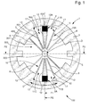
- the oscillating mechanism 1 comprises at least one anchor 2 to an external device, in particular a plate or a bridge of a movement 1000.
- This anchor 2 constitutes the second rigid element 600.
- the intermediate rigid element 400 of the oscillating mechanism 1 comprises a first component 3 movable at least pivotally about a first instantaneous pivot axis in the vicinity of a theoretical axis of pivoting D fixed and fixed position relative to this anchor 2, or as the case may be.
- these anchorages 2 if there are more than one, as in the case of Figures 1 to 3 where two anchors 2 are shown.
- the first rigid element 200 of the oscillating mechanism 1 comprises a second component 5 in the vicinity of this axis D.
- first component 3 and the second component 5 are connected directly or indirectly to one another and one of them, first component 3 or second component 5, comprises means for receiving a pulse generated by external or internal motor means to the oscillating mechanism 1.
- This pulse is exerted against elastic return means 10, which comprises the oscillating mechanism 1, and which are arranged to oscillate the first component 3 about the first instantaneous axis of pivoting.
- the oscillating mechanism 1 is in one piece, and the only means for fixing the oscillating mechanism 1 to an external device are constituted by the anchor 2, or, as the case may be, the 2.
- the resilient biasing means 10 constitute a resilient virtual pivot, which dispenses the oscillating mechanism 1 of any fixation on a shaft or pivot.
- these elastic return means 10 comprise means for balancing the forces exerted on the first component 3 to maintain the first instantaneous axis of pivoting closest to the theoretical axis of pivoting D.
- the elastic return means 10 comprise at least one first elastic element 11 whose angular displacement is limited to the value of a pivoting stroke of the first component 3.
- This pivoting stroke of the first component 3 is itself determined by first angular deflection limiting means 17 with respect to each radial coming from the axis D and joining each anchor 2.
- each first elastic element 11 has a stiffness much lower than that of the first component 3, in a ratio less than 0.30 relative to that of the first component 3.
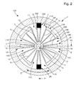
- first elastic element 11 extends radially with respect to the axis D and from the anchor 2, to the first component 3 as visible on the figure 1 , or to a third component 6 connected directly or indirectly to the first component 3 as visible on the figure 2 .
- the first elastic element 11 is called a dihedron and is in the shape of a vee or vee truncated. The tip of this vee is directed towards the axis D.
- the first elastic element 11 comprises a first elastic arm 12 which extends radially with respect to the axis D, from the anchor 2 to the axis D, until at a connecting surface 7 located near the second component 5. This connecting surface 7 can be reduced to its simplest expression, that is to say, punctual.
- the first elastic element 11 further comprises a second elastic arm 13 extending radially with respect to the axis D, from the connecting surface 7, to the first component 3, or to a third component 6 which is connected directly or indirectly to the first component 3 as visible on the figure 2 .
- the first elastic arm 12 and the second elastic arm 13 are identical. Preferably, they are symmetrical with respect to a radial resulting from the theoretical axis D.
- the elastic return means 10 comprise at least a second elastic element 14 interposed directly or indirectly between the first elastic element 11 and the first component 3.
- the angular displacement of the second elastic element 14 is limited to the difference between, the pivoting stroke of the first component 3 determined by the angular deflection limiting means 17 on the one hand, and the angular deflection allowed by the first elastic element 11 on the other hand. It will be understood that, with regard to the angular pivoting displacement of the first component 3, it is substantially equal to the accumulation of the angular deflections of the first elastic element 11 and the second elastic element 14 associated together.
- this first element 11 and this second element 14 are of similar geometry and stiffness characteristics, have a displacement of approximately +/- 15 ° each, the first component 3 then has a displacement of about +/- 30 °.
- each second elastic element 14 is advantageously of much lower stiffness than that of the first component 3, in a ratio of less than 0.30 with respect to that of the first component 3.
- the oscillating mechanism 1 comprises at least a third component 6 connected to the anchor 2 by at least one first elastic element 11, and to the first component 3 by at least one second elastic element 14.
- all the first elastic elements 11 of the same oscillating mechanism 1 are identical.
- all the second elastic members 14 of the same oscillating mechanism 1 are identical.
- all the third components 6 of the same oscillating mechanism 1, when it comprises, are identical.
- the second elastic element 14 like the first elastic element 11, it preferably extends radially with respect to the axis D and since, or the first elastic element 11 or a third component 6 interposed between the second component 5 and the first component 3, to the first component 3.
- the second elastic element 14 is vee-shaped or vee truncated.
- the tip of this vee is directed towards the axis D.
- the second elastic element 14 comprises a first elastic arm 15 extending radially with respect to the axis D since, or the first elastic element 11 or the third component 6 , towards the axis D, to a connecting surface 7A located near the second component 5.
- it further comprises a second elastic arm 16 extending radially relative to the axis D from the connecting surface 7A up to to the first component 3 or to another component connected directly or indirectly to the first component 3.
- the connecting surface 7A can also be reduced to its simplest expression, that is to say point.
- the first elastic arm 15 and the second elastic arm 16 are identical. Preferably, they are symmetrical with respect to a radial from the axis D.
- the first elastic arm 12 and the second elastic arm 13 of the first elastic element 11, and the first elastic arm 15 and the second elastic arm 16 of the second elastic element 14 are all identical to each other. Preferably, they are symmetrical two by two with respect to a radial from the axis D.
- the first component 3 is rigidly connected to the second component 5 by at least one arm 8, and preferably by a plurality of arms 8.
- each arm 8 is of greater rigidity than that of each of the return means elastic 10.
- the oscillating mechanism 1 comprises at least a third component 6 connected to the anchor 2 by at least one first elastic element 11, and to the first component 3 by at least one second elastic element 14.
- the third component 6 is rigidly connected to the second component 5 by at least one rigid arm 8.
- the second component 5 constitutes, with the third component 6, or as the case the third components 6, and with the arm 8, or as the case 8 arms, a second mobile 9 rigid, which is pivotally movable about a second instantaneous axis of pivoting very close to the axis D.
- the elastic return means 10 comprise means for balancing the forces exerted on the second mobile 9 to maintain the second axis instantaneous as close as possible to the theoretical axis of pivoting D.
- the oscillating mechanism 1 comprises two anchors 2; 2A to an external device, for example to a fixed point of a plate, or other.
- These two anchors 2, 2A are preferably symmetrical with respect to the axis D.
- the oscillating mechanism 1 in the free state and at rest, is symmetrical with respect to to a plane of symmetry PS, here P1, perpendicular to the axis D and passing through at least one anchorage 2.
- the oscillating mechanism 1, in the free state and at a standstill is preferably symmetrical with respect to another plane of symmetry PS, here a plane P2 perpendicular to the axis D and perpendicular to a straight line joining the two anchors 2,2A, when it has two so arranged.
- the oscillating mechanism 1 in the free state and at rest, is symmetrical with respect to the axis D.
- the oscillating mechanism 1 may comprise a plurality of anchors 2 to an external device, equidistant from each other and with respect to the axis D.
- the oscillating mechanism 1 comprises a plurality of first elastic elements 11, grouped two by two on each side of each anchor 2.
- the oscillating mechanism 1 comprises a plurality of second elastic elements 14, which are grouped two by two on either side of at least one bearing zone 19, by which these second elastic elements 14 are attached to the first component 3 .
- the oscillating mechanism 1 comprises at least one third component 6 connected to the anchor 2 by at least one first elastic element 11, and to the first component 3 by at least one second elastic element 14, it advantageously comprises, at the level of the first component 3, second angular displacement limitation means 18 of the third component 6.
- the anchor 2 is still other means for limiting the angular clearance of the third component 6 at side faces 6A, 6B.
- the radius of inertia of the first component 3 with respect to the axis D is greater than that of the second component 5 with respect to the same axis.
- the first component 3 and the second component 5 are made in the form of a trellis of thin blades or thin flexible blades.
- third component 6 is made in the form of a lattice of thin blades or thin flexible blades.
- the first component 3 and the third component 6 can also be dense, depending on the desired level of inertia for these components.
- the elastic deformation of the components of the oscillating mechanism 1 is essentially flat, all the components deforming elastically in the same plane or in planes parallel to each other.
- the oscillating mechanism 1 while keeping a substantially flat first component 3, it is possible, in an alternative embodiment not illustrated by the figures, to arrange the oscillating mechanism 1, so that the elastic deformation of some of its components comprises a component according to a normal to the plane P of the first component 3.
- the elastic return means 10 are distributed over several parallel layers, and the elements that compose them are arranged and joined to each other so as to allow a angular displacement of the first movable component 3 of greater amplitude than that which is allowed by the movements of the components, and by the stop positions they can represent for each other. It is thus possible to realize any amplitude, in particular greater than a 360 ° revolution of the first component 3.
- the oscillating mechanism 1 comprises stop means or at least one pawl, so as to retain in position spaced from its equilibrium position all or part of the elements that make up the elastic return means 10, or in such a way as to keep the first moving component 3 at a position away from its equilibrium position, or so as to retain the second mobile 9 in its position away from its equilibrium position.
- the invention relates to the use of such an oscillating mechanism 1 for the production of a power transmission mobile 100 for decoupling the inertia of a part of a cog in a watch movement 1000 or a part of watchmaker 10000.
- the invention particularly relates to the application of such a mobile energy transmission to a constant force mechanism, where the mobile energy transmission 100 is a reservoir of energy, called “buffer" between the barrel and the escapement of a timepiece, thus making it possible to transmit a constant torque to the escapement.
- the mobile energy transmission 100 is a reservoir of energy, called “buffer” between the barrel and the escapement of a timepiece, thus making it possible to transmit a constant torque to the escapement.
- the skilled person will easily use the mobile according to the invention to integrate it with a constant-force device Type Jeanneret, as described by the document " General Theory of Watchmaking, by Léopold Defossez, Swiss Chamber of Watchmaking, La Chaux-de-Fonds » Volume II, page 129 .
- the invention allows, again, the decoupling of the inertia of a part of a cog: in the case of a vortex, for example, the inertia of the cog in motion at each pulse is large, and penalizes the performance of the exhaust.
- a flexible wheel according to the invention interposed between the high inertia elements and the exhaust, allows the exhaust to move quickly before the large inertia is set in motion, thereby improving the efficiency of the exhaust .
- This application is particularly innovative, and uses with advantage the compactness of the mobile according to the invention.
- the invention is useful for storing energy, before delivering it at the right moment to a mobile receiver, it is also entirely appropriate for protecting a fragile organ from a movement against shocks, or, moreover, general, against strong accelerations.
- its application to the protection of a fragile exhaust against shocks is effective. Indeed, when taking rest or during shocks on the needles, the torque transmitted in the train can be momentarily much higher than the torque of the barrel.
- an exhaust made of fragile material such as silicon or another material obtained by MEMS technologies or obtained by a "LIGA" process or similar, possibly skeletonized to the extreme for its lightening, it is likely to break.
- the means used may consist of a board pivoted freely on the axis of the pinion, or a pinion pivoted on the axis of the board, with return spring (spiral spring or coil spring) between the pinion and the board.
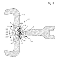
- the invention relates to a power transmission mobile 100 for a watch movement 1000, and this mobile power transmission 100 comprises such an oscillating mechanism 1 between at least a first mobile transmitter 2E of said movement 1000 of a on the one hand, and at least one second mobile receiver 3R of the movement 1000 on the other hand.
- the mobile 1 comprises at least one degree of freedom in pivoting about the theoretical axis of pivoting D.
- the first elastic return means 300 and the second elastic return means 500 together constitute elastic return means 10 providing a direct or indirect elastic connection between a first axial portion 200 and a second peripheral portion 600.
- axial part 200 is located in the vicinity of the pivot axis D and cooperates with the first mobile transmitter 2E or respectively the second mobile receiver 3R
- the second peripheral portion 600 is radially away from the pivot axis D and cooperates with the second mobile receiver 3R or respectively the first mobile transmitter 2E.
- These elastic return means 10 are arranged for, as the case may be, absorb, store or release energy during an angular deflection in pivoting around a secondary axis D1 parallel to or coinciding with the pivot axis D, between the first axial portion 200 and the second peripheral portion 600.
- the first axial portion 200 and the second peripheral portion 600 are coaxial in the free state, and the elastic return means 10 are still arranged to maintain the coaxial first axial part 200 and the second peripheral part 600 during the deformation of the elastic return means 10.
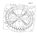
- the second peripheral portion 600 is rigid and dimensionally stable
- the elastic connection produced by the elastic return means 10 is substantially flat in a plane perpendicular to the theoretical axis of pivoting D.
- the angular deflection in pivoting of the second peripheral portion 600 is several degrees or several tens of degrees.
- the elastic return means 10 comprise at least one arm 70 extending between said first axial portion 200 and said second peripheral portion 600, and this arm 70 comprises at least one elastic portion.
- the arm 70 is elastic.
- the elastic return means 10 comprise at least one arm 70 comprising at least one rigid portion 120 extending between the first axial portion 200 and the second peripheral portion 600 to which it is connected respectively by at least a first elastic blade 80 and at least one second elastic blade 90.
- the elastic return means 10 comprise a plurality of such arms 70 located in planes parallel to each other or to each other and all perpendicular to the theoretical axis of pivoting D.
- the elastic return means 10 comprise at least one arm 70 comprising a plurality of rigid portions 120 extending between the first axial portion 200 and the second peripheral portion 600 to which they are connected respectively by at least a first elastic blade 80A of a first rigid portion 120A and at least a second elastic blade 90B of a second said rigid portion 120B, these rigid portions 120 being connected to each other exclusively by an elastic portion 130 .
- this elastic part 130 comprises at least one elastic blade 140.
- the energy transmission mobile 100 adopts a butterfly-type configuration comprising at least one arm 70 comprising at least one rigid portion 120 extending between said first axial portion 200 and said second peripheral portion 600 to which it is respectively connected by the less a first resilient blade 80 and at least a second resilient blade 90, the rigid portion 120 constituting an intermediate mass movable substantially pivotally about the theoretical axis of pivoting D.
- the power transmission mobile 100 adopts a four-necked RCC-type configuration, comprising two non-aligned arms 70 each having at least one rigid portion 120 extending between the first axial portion 200 and the second peripheral portion 600, to which it is connected respectively by at least a first elastic blade 80 and by at least a second elastic blade 90.
- the two arms 70 form between them an angle centered substantially on the theoretical axis of pivoting D and close to 90 °.
- the elastic return means 10 have an angular displacement limited to a pivoting stroke of the first portion 200 relative to the second portion 600 determined by angular deflection limiting means.
- the elastic return means 10 have a stiffness much lower than that of the first part 200 and the second part 600, in a ratio less than 0.30 compared to the lowest stiffness of the first part 200 or part two 600.
- the elastic return means 10 consist of substantially radial blades with respect to the theoretical axis of pivoting D.
- At least one of the elastic return means is in the form of a spiral spring.
- the oscillating mechanism 1 is a monobloc balance-spring balance or silicon or the like.
- the energy transmission mobile 100 is made of a micro-machinable material, or silicon, or quartz, or one of their compounds, or an alloy derived from MEMS technology, or an alloy such as obtained by the "LIGA" process, or an at least partially amorphous material. In a particular embodiment, it is made of a combination of some of these materials, the material being a rigid Young modulus material greater than 80000 MPa.
- the invention also relates to a watch movement 1000 comprising at least one such mobile energy transmission 100.
- the invention also relates to a timepiece 10000 comprising at least one such movement, and / or at least one such mobile energy transmission 100, or / and at least one such oscillating mechanism 1.
- the invention overcomes the difficulties of manufacture and adjustment, or assembly and pitonnage, which are related to certain components such as spiral springs. It provides a very compact solution to the problem of producing mechanical oscillators mass-spring type.
- the invention allows the realization of a mechanism of very small thickness, and allows new possibilities of equipment of timepieces, especially with complications always consuming volume. The possibility of getting rid of the pivots represents a great technological progress in watchmaking.
- the accuracy of realization is very high thanks to the use of micro-machinable materials, in particular silicon or silicon oxide, or similar.
- the control of the masses, and especially the inertia, is total. This means that a direct consequence of the implementation of the invention is a very great simplification of the settings on a timepiece, or even a deletion of the settings.
- the invention also relates to the use of such a power transmission mobile 100 to decouple the inertia of a part of a cog in a watch movement comprising on the one hand an exhaust and on the other hand a second movable inertia greater than that of said exhaust, by the interposition of said energy transmission mobile 100 either directly or in a train, between said exhaust and said second mobile, so as to allow a rapid pivoting of said exhaust before said second mobile is set in motion at each pulse.
- the invention also relates to the use of a mobile energy transmission 100, wherein said second mobile is a vortex or a carousel.
- the invention also relates to the use of a power transmission mobile 100, wherein said exhaust comprises an escape wheel constituted by such a power transmission mobile 100.
- the invention also relates to the use of such a power transmission mobile 100 for absorbing excess energy in a clockwork train, when a torque transmitted to the wheel by a shock or a strong acceleration or during the the resting point of the exhaust is momentarily much higher than the torque of a cylinder supplying said energy movement, realizing at least one of the elements of said train in the form of a said mobile energy transmission 100.
- the invention also relates to the use of such a power transmission mobile 100 for a said watch movement comprising an escapement, characterized in that said exhaust comprises an escape wheel constituted by a said transmission of energy transmission 100.
- the invention also relates to the use of such a power transmission mobile 100 to absorb excess energy in a clockwork movement comprising a gear train and at least one friction coupling, when a torque transmitted to the wheel by a shock or a strong acceleration or during the quiescent of the exhaust is momentarily much higher than the torque of a cylinder supplying said energy movement, realizing at least one of the elements of said train in the form of a said transmission mobile of energy 100, to decrease the instantaneous torque peak transmitted through said friction coupling.
- the invention also relates to the use of such a power transmission mobile 100 for a said chronograph watch movement comprising at least one friction coupling.
- the invention also relates to the use of such a mobile energy transmission 100 for a watch movement comprising, between an energy storage cylinder and an exhaust, a train comprising at least one said mobile energy transmission 100 to constitute a buffer energy reservoir between said cylinder and said exhaust, to transmit a constant torque to said exhaust.
- the invention also relates to the use of such a mobile energy transmission 100 for a watch movement comprising two boards interconnected by an angular return spring consisting of a said mobile energy transmission 100, for sandwiching the teeth of a pinion, and constitute a gear mechanism without play.
- the invention also relates to the use of such a power transmission mobile 100 in a watch movement in which said first mobile transmitter 2E or said second mobile receiver 3R said movement 1000 is held fixed in anchorage relative to a platinum or a bridge that includes said watch movement.
Priority Applications (1)
| Application Number | Priority Date | Filing Date | Title |
|---|---|---|---|
| EP15153532.5A EP2894520A3 (de) | 2010-07-19 | 2011-07-04 | Schwingungsmechanismus mit elastischem und beweglichen Zapfen zur Energieübertragung |
Applications Claiming Priority (4)
| Application Number | Priority Date | Filing Date | Title |
|---|---|---|---|
| CH11982010A CH703464B1 (fr) | 2010-07-19 | 2010-07-19 | Mécanisme oscillant à pivot élastique. |
| EP10191774.8A EP2455821B2 (de) | 2010-11-18 | 2010-11-18 | Energieübertragungrad |
| EP15153532.5A EP2894520A3 (de) | 2010-07-19 | 2011-07-04 | Schwingungsmechanismus mit elastischem und beweglichen Zapfen zur Energieübertragung |
| EP11733619.8A EP2596406B1 (de) | 2010-07-19 | 2011-07-04 | Oszillationsmechanismus mit elastischem und mobilem drehzapfen zur energieübertragung |
Related Parent Applications (2)
| Application Number | Title | Priority Date | Filing Date |
|---|---|---|---|
| EP11733619.8A Division-Into EP2596406B1 (de) | 2010-07-19 | 2011-07-04 | Oszillationsmechanismus mit elastischem und mobilem drehzapfen zur energieübertragung |
| EP11733619.8A Division EP2596406B1 (de) | 2010-07-19 | 2011-07-04 | Oszillationsmechanismus mit elastischem und mobilem drehzapfen zur energieübertragung |
Publications (2)
| Publication Number | Publication Date |
|---|---|
| EP2894520A2 true EP2894520A2 (de) | 2015-07-15 |
| EP2894520A3 EP2894520A3 (de) | 2016-06-22 |
Family
ID=44358131
Family Applications (2)
| Application Number | Title | Priority Date | Filing Date |
|---|---|---|---|
| EP15153532.5A Withdrawn EP2894520A3 (de) | 2010-07-19 | 2011-07-04 | Schwingungsmechanismus mit elastischem und beweglichen Zapfen zur Energieübertragung |
| EP11733619.8A Active EP2596406B1 (de) | 2010-07-19 | 2011-07-04 | Oszillationsmechanismus mit elastischem und mobilem drehzapfen zur energieübertragung |
Family Applications After (1)
| Application Number | Title | Priority Date | Filing Date |
|---|---|---|---|
| EP11733619.8A Active EP2596406B1 (de) | 2010-07-19 | 2011-07-04 | Oszillationsmechanismus mit elastischem und mobilem drehzapfen zur energieübertragung |
Country Status (6)
| Country | Link |
|---|---|
| US (1) | US9201398B2 (de) |
| EP (2) | EP2894520A3 (de) |
| JP (1) | JP5551312B2 (de) |
| CN (1) | CN103097965B (de) |
| HK (1) | HK1185155A1 (de) |
| WO (1) | WO2012010408A1 (de) |
Cited By (7)
| Publication number | Priority date | Publication date | Assignee | Title |
|---|---|---|---|---|
| EP3147725A1 (de) * | 2015-09-28 | 2017-03-29 | Nivarox-FAR S.A. | Oszillator mit rotierendem gesperr |
| FR3048790A1 (fr) * | 2016-03-14 | 2017-09-15 | Lvmh Swiss Mft Sa | Mecanisme pour piece d'horlogerie, mouvement horloger et piece d'horlogerie comprenant un tel mecanisme. |
| EP3327515A1 (de) * | 2016-11-23 | 2018-05-30 | ETA SA Manufacture Horlogère Suisse | Sich drehender resonator mit einer flexiblen führung, der von einer freien ankerhemmung gehalten wird |
| EP3502784A1 (de) * | 2017-12-22 | 2019-06-26 | Patek Philippe SA Genève | Uhrresonator mit flexibler führung |
| EP3598243A1 (de) * | 2018-07-19 | 2020-01-22 | Patek Philippe SA Genève | Uhrmechanismus mit organ, das sich in sprüngen bewegt |
| EP4012505A1 (de) * | 2020-12-11 | 2022-06-15 | Patek Philippe SA Genève | Uhrvorrichtung mit antiblockiervorrichtung |
| EP4276543A1 (de) * | 2022-05-10 | 2023-11-15 | The Swatch Group Research and Development Ltd | Gesamtheit von flexiblen führungen für sich drehenden resonatormechanismus eines uhrwerks |
Families Citing this family (47)
| Publication number | Priority date | Publication date | Assignee | Title |
|---|---|---|---|---|
| EP2466396A1 (de) * | 2010-12-15 | 2012-06-20 | The Swatch Group Research and Development Ltd. | Magnetische Abschirmung für Spiralunruh einer Uhr |
| EP2706416B1 (de) | 2012-09-07 | 2015-11-18 | The Swatch Group Research and Development Ltd | Flexibler Anker mit konstanter Kraft |
| DE212014000091U1 (de) | 2013-03-22 | 2015-10-23 | Omega Sa | Koaxialer einteiliger Hemmungsanker |
| EP2796940A3 (de) * | 2013-04-23 | 2016-05-04 | Rolex Sa | Uhrkomponente zur Aufnahme eines Organs durch Einpressen |
| EP2871537B1 (de) * | 2013-11-06 | 2017-01-04 | ETA SA Manufacture Horlogère Suisse | Armbanduhr mit verbesserter Gangreserve |
| CH708937B1 (fr) | 2013-12-12 | 2020-03-31 | Richemont Int Sa | Elément oscillant pour mouvement horloger. |
| EP2911012B1 (de) * | 2014-02-20 | 2020-07-22 | CSEM Centre Suisse d'Electronique et de Microtechnique SA - Recherche et Développement | Oszillator einer Uhr |
| CH709881A2 (fr) * | 2014-07-14 | 2016-01-15 | Nivarox Sa | Guidage flexible horloger. |
| EP2977830B1 (de) * | 2014-07-23 | 2017-08-30 | Nivarox-FAR S.A. | Uhrhemmungsmechanismus mit konstanter Kraft |
| CH709920A2 (fr) * | 2014-07-24 | 2016-01-29 | Eta Sa Manufacture Horlogère Suisse | Ensemble à mobile de freinage d'horlogerie. |
| EP3457221B1 (de) | 2014-09-16 | 2022-08-10 | Patek Philippe SA Genève | Oszillator einer uhr mit flexiblem zapfen |
| CH710188A2 (fr) * | 2014-09-26 | 2016-03-31 | Eta Sa Manufacture Horlogère Suisse | Résonateur d'horlogerie paraxial et isochrone. |
| CH710278B1 (fr) * | 2014-10-24 | 2024-02-15 | Richemont Int Sa | Organe réglant pour un mouvement horloger mécanique. |
| EP3021174A1 (de) | 2014-11-17 | 2016-05-18 | LVMH Swiss Manufactures SA | Monolithischer Uhrregler, Uhrwerk und Uhr mit einem solchem Uhrregler |
| EP3032351A1 (de) * | 2014-12-09 | 2016-06-15 | LVMH Swiss Manufactures SA | Uhrmechanismus, Uhrwerk und Uhr mit solch einem Mechanismus |
| EP3032352A1 (de) | 2014-12-09 | 2016-06-15 | LVMH Swiss Manufactures SA | Uhrregler, Uhrwerk und Uhr mit solch einem Regler |
| CN107003641B (zh) * | 2014-12-12 | 2021-02-19 | 西铁城时计株式会社 | 钟表部件以及钟表部件的制造方法 |
| EP3037893B1 (de) | 2014-12-22 | 2018-02-28 | Patek Philippe SA Genève | Mikromechanische Komponente oder Uhr mit flexiblem Führungsdraht |
| CH710692B1 (fr) * | 2015-02-03 | 2021-09-15 | Eta Sa Mft Horlogere Suisse | Mécanisme oscillateur d'horlogerie. |
| CH710759A2 (fr) * | 2015-02-20 | 2016-08-31 | Nivarox Far Sa | Oscillateur pour une pièce d'horlogerie. |
| EP3130966B1 (de) * | 2015-08-11 | 2018-08-01 | ETA SA Manufacture Horlogère Suisse | Mechanisches uhrwerk, das mit einem bewegungsrückkopplungssysteme ausgestattet ist |
| EP3147726A1 (de) * | 2015-09-24 | 2017-03-29 | ETA SA Manufacture Horlogère Suisse | Anzeigevorrichtung für uhr, die einen anzeiger mit starker umwucht umfasst |
| EP3182214A1 (de) * | 2015-12-16 | 2017-06-21 | Société anonyme de la Manufacture d'Horlogerie Audemars Piguet & Cie | Mechanischer oszillator für eine uhr, regulierungsmechanismus, der diesen mechanischen oszillator umfasst, und entsprechendes uhrwerk |
| EP3200029B1 (de) * | 2016-01-29 | 2021-05-19 | ETA SA Manufacture Horlogère Suisse | Resonatormechanismus eines uhrwerks |
| CH712105A2 (fr) | 2016-02-10 | 2017-08-15 | Swatch Group Res & Dev Ltd | Mécanisme résonateur d'horlogerie. |
| FR3048791B1 (fr) * | 2016-03-14 | 2018-05-18 | Lvmh Swiss Manufactures Sa | Mecanisme pour piece d'horlogerie et piece d'horlogerie comprenant un tel mecanisme |
| US11029649B2 (en) | 2016-03-14 | 2021-06-08 | LVHM Swiss Manufactures SA | Device for timepiece, clockwork movement and timepiece comprising such a device |
| EP3326963B1 (de) * | 2016-11-23 | 2020-01-01 | The Swatch Group Research and Development Ltd | Flexibles blatt für uhrwerk und herstellungsverfahren |
| FR3059792B1 (fr) * | 2016-12-01 | 2019-05-24 | Lvmh Swiss Manufactures Sa | Dispositif pour piece d'horlogerie, mouvement horloger et piece d'horlogerie comprenant un tel dispositif |
| CH713288A1 (fr) | 2016-12-23 | 2018-06-29 | Sa De La Manufacture Dhorlogerie Audemars Piguet & Cie | Composant monolithique flexible pour pièce d'horlogerie. |
| CN106986297A (zh) * | 2017-04-28 | 2017-07-28 | 茹朝贵 | 一种减震设备 |
| EP3416001B1 (de) * | 2017-06-13 | 2022-04-13 | Patek Philippe SA Genève | Herstellungsverfahren eines oszillators mit flexiblem zapfen |
| EP3451072B1 (de) * | 2017-08-29 | 2023-10-25 | The Swatch Group Research and Development Ltd | Isochrones drehgelenk für uhrresonator |
| JP7006065B2 (ja) * | 2017-09-14 | 2022-01-24 | セイコーエプソン株式会社 | 時計用部品、時計用ムーブメントおよび時計 |
| CN111344640A (zh) * | 2017-10-02 | 2020-06-26 | 爱彼钟表业制造有限公司 | 带有具有旋转重锤和共同返回力的谐波振荡器的钟表调校设备 |
| EP3525046A1 (de) | 2018-02-12 | 2019-08-14 | The Swatch Group Research and Development Ltd | Uhrwerkoszillator, der für winkelbeschleunigungen des tragens unempfindlich ist |
| EP3537593B1 (de) * | 2018-03-09 | 2024-04-24 | ETA SA Manufacture Horlogère Suisse | Rotationsvorrichtung für ein zahnrad |
| JP7052625B2 (ja) * | 2018-08-02 | 2022-04-12 | セイコーエプソン株式会社 | 時計用部品、ムーブメント、時計および時計用部品の製造方法 |
| JP6915602B2 (ja) * | 2018-10-24 | 2021-08-04 | セイコーエプソン株式会社 | 時計部品および時計 |
| EP3663869B1 (de) * | 2018-12-06 | 2021-06-16 | Montres Breguet S.A. | Schlagwerkmechanismus einer uhr mit hängehammer |
| EP3771947A1 (de) * | 2019-07-29 | 2021-02-03 | ETA SA Manufacture Horlogère Suisse | Führungsvorrichtung zum schwenken und resonatormechanismus eines uhrwerks für eine schwenkbare masse |
| EP3812842B1 (de) * | 2019-10-24 | 2023-11-29 | The Swatch Group Research and Development Ltd | Schwenkbare führungsvorrichtung für eine schwenkbare masse, und resonatormechanismus einer uhr |
| EP3910425A1 (de) * | 2020-05-13 | 2021-11-17 | The Swatch Group Research and Development Ltd | Uhrwerk, das eine hemmung mit einem zahnrad und einer arretierung umfasst |
| EP3919988A1 (de) * | 2020-06-04 | 2021-12-08 | Montres Breguet S.A. | Gelenkmechanismus eines uhrwerks mit flexibler führung |
| EP3992729A1 (de) * | 2020-10-29 | 2022-05-04 | The Swatch Group Research and Development Ltd | Flexible führung mit verschiebetisch für einen rotierenden resonatormechanismus, insbesondere eines uhrwerks |
| EP3992728A1 (de) * | 2020-10-29 | 2022-05-04 | The Swatch Group Research and Development Ltd | Flexible führung mit verschiebetisch für einen rotierenden resonatormechanismus, insbesondere eines uhrwerks |
| EP4137892A1 (de) * | 2021-08-20 | 2023-02-22 | Montres Breguet S.A. | Blendenartige auslösevorrichtung, insbesondere für uhrwerke |
Citations (8)
| Publication number | Priority date | Publication date | Assignee | Title |
|---|---|---|---|---|
| CH6659A (fr) | 1893-06-05 | 1893-12-30 | Achille Lambert | Roue pour montres |
| CH343897A (fr) | 1959-04-06 | 1959-12-31 | Rolex Montres | Pièce d'horlogerie |
| DE2714020A1 (de) | 1977-03-30 | 1978-10-12 | Werner Beiter | Zahnrad aus kunststoff und verfahren zu seiner herstellung |
| FR2641351A1 (fr) | 1988-12-29 | 1990-07-06 | Alcatel Business Systems | Pignon anti-bruit |
| EP1253275A1 (de) | 2001-04-25 | 2002-10-30 | Siemens Aktiengesellschaft | Getriebe-Antriebseinheit, insbesondere Fensterheber- bzw. Schiebedachantrieb für ein Kraftfahrzeug, sowie Verfahren zu deren Herstellung |
| EP1457844A2 (de) | 2003-03-12 | 2004-09-15 | Pierre Kunz SA | Drehteil für Uhren |
| EP1580624A2 (de) | 2004-03-25 | 2005-09-28 | Pierre Kunz SA | Drehteil zur Kontaktierung mit einem anderen beweglichen oder unbeweglichen Bauteil |
| EP1870784A2 (de) | 2006-06-23 | 2007-12-26 | Omega SA | Mikromechanische Triebfeder mit durch Stöße geregelter Drehung |
Family Cites Families (18)
| Publication number | Priority date | Publication date | Assignee | Title |
|---|---|---|---|---|
| US965505A (en) * | 1907-11-29 | 1910-07-26 | Frederic Ecaubert | Compensating balance-wheel. |
| US965506A (en) * | 1908-10-22 | 1910-07-26 | Frederic Ecaubert | Compensating balance for timepieces. |
| CH67067A (fr) * | 1914-01-16 | 1914-11-02 | Kemplay Irwin Thomas | Appareil pour le traitment de liquides avec un fluide gazeux |
| CH166267A (fr) * | 1932-12-20 | 1933-12-31 | Schaad Ernest | Balancier élastique pour mouvements de montres et autres mouvements d'horlogerie. |
| US2274832A (en) * | 1939-04-28 | 1942-03-03 | John W Hobbs Corp | Flexible coupling |
| CH479105A (fr) * | 1967-01-17 | 1969-11-14 | Balanciers Reunies Sa | Balancier amortisseur de chocs pour pièce d'horlogerie |
| CH474101A (fr) * | 1967-01-27 | 1969-06-15 | Balanciers Reunies Sa | Balancier amortisseur de chocs pour pièce d'horlogerie |
| JP3498315B2 (ja) * | 1997-08-28 | 2004-02-16 | セイコーエプソン株式会社 | バネ、ゼンマイ、これらを利用した駆動機構、および時計 |
| EP1013949A1 (de) * | 1998-12-17 | 2000-06-28 | Sysmelec SA | Flexibles Scharnier mit grossem Schwenkwinkel und erhöhter Steifigkeit |
| EP1843225B1 (de) * | 2006-04-07 | 2009-07-15 | ETA SA Manufacture Horlogère Suisse | Mechanischer Wechsler zum Drehantreiben eines Rades aus einer einzelnen Richtung |
| TWI461865B (zh) * | 2006-06-23 | 2014-11-21 | Omega Sa | 用於機械式時計機心之擺輪游絲調節系統及具有此系統之時計 |
| CH714952B1 (fr) * | 2007-05-08 | 2019-10-31 | Patek Philippe Sa Geneve | Composant horloger, son procédé de fabrication et application de ce procédé. |
| CH708113B1 (de) * | 2007-09-13 | 2014-12-15 | Stéphane Von Gunten | Anker für eine Uhrenhemmung. |
| EP2104008A1 (de) * | 2008-03-20 | 2009-09-23 | Nivarox-FAR S.A. | Monoblock-Regulierungsorgan und sein Herstellungsverfahren |
| EP2145857B1 (de) * | 2008-07-10 | 2014-03-19 | The Swatch Group Research and Development Ltd. | Verfahren zur Herstellung eines mikromechanischen Bauteils |
| EP2189854A1 (de) * | 2008-11-21 | 2010-05-26 | Nivarox-FAR S.A. | Verfahren zur Herstellung eines mikromechanischen Bauteils |
| EP2410387B1 (de) * | 2010-07-19 | 2016-07-06 | Nivarox-FAR S.A. | Unruh mit Trägheitsregulierung ohne Einsatzteil |
| EP2410386B1 (de) * | 2010-07-19 | 2018-10-03 | Nivarox-FAR S.A. | Unruh mit Trägheitsregulierung mit Einsatzteil |
-
2011
- 2011-07-04 CN CN201180035340.2A patent/CN103097965B/zh active Active
- 2011-07-04 WO PCT/EP2011/061244 patent/WO2012010408A1/fr active Application Filing
- 2011-07-04 EP EP15153532.5A patent/EP2894520A3/de not_active Withdrawn
- 2011-07-04 US US13/810,937 patent/US9201398B2/en active Active
- 2011-07-04 JP JP2013520042A patent/JP5551312B2/ja active Active
- 2011-07-04 EP EP11733619.8A patent/EP2596406B1/de active Active
-
2013
- 2013-11-05 HK HK13112422.8A patent/HK1185155A1/xx unknown
Patent Citations (8)
| Publication number | Priority date | Publication date | Assignee | Title |
|---|---|---|---|---|
| CH6659A (fr) | 1893-06-05 | 1893-12-30 | Achille Lambert | Roue pour montres |
| CH343897A (fr) | 1959-04-06 | 1959-12-31 | Rolex Montres | Pièce d'horlogerie |
| DE2714020A1 (de) | 1977-03-30 | 1978-10-12 | Werner Beiter | Zahnrad aus kunststoff und verfahren zu seiner herstellung |
| FR2641351A1 (fr) | 1988-12-29 | 1990-07-06 | Alcatel Business Systems | Pignon anti-bruit |
| EP1253275A1 (de) | 2001-04-25 | 2002-10-30 | Siemens Aktiengesellschaft | Getriebe-Antriebseinheit, insbesondere Fensterheber- bzw. Schiebedachantrieb für ein Kraftfahrzeug, sowie Verfahren zu deren Herstellung |
| EP1457844A2 (de) | 2003-03-12 | 2004-09-15 | Pierre Kunz SA | Drehteil für Uhren |
| EP1580624A2 (de) | 2004-03-25 | 2005-09-28 | Pierre Kunz SA | Drehteil zur Kontaktierung mit einem anderen beweglichen oder unbeweglichen Bauteil |
| EP1870784A2 (de) | 2006-06-23 | 2007-12-26 | Omega SA | Mikromechanische Triebfeder mit durch Stöße geregelter Drehung |
Cited By (28)
| Publication number | Priority date | Publication date | Assignee | Title |
|---|---|---|---|---|
| EP3147725A1 (de) * | 2015-09-28 | 2017-03-29 | Nivarox-FAR S.A. | Oszillator mit rotierendem gesperr |
| CN106557009A (zh) * | 2015-09-28 | 2017-04-05 | 尼瓦洛克斯-法尔股份有限公司 | 具有旋转制动器的振荡器 |
| US9921547B2 (en) | 2015-09-28 | 2018-03-20 | Nivarox-Far S.A. | Oscillator with rotating detent |
| CN106557009B (zh) * | 2015-09-28 | 2019-05-07 | 尼瓦洛克斯-法尔股份有限公司 | 具有旋转制动器的振荡器 |
| FR3048790A1 (fr) * | 2016-03-14 | 2017-09-15 | Lvmh Swiss Mft Sa | Mecanisme pour piece d'horlogerie, mouvement horloger et piece d'horlogerie comprenant un tel mecanisme. |
| WO2017157712A1 (fr) * | 2016-03-14 | 2017-09-21 | Lvmh Swiss Manufactures Sa | Mécanisme pour pièce d'horlogerie, mouvement horloger et pièce d'horlogerie comprenant un tel mécanisme |
| TWI709009B (zh) * | 2016-03-14 | 2020-11-01 | 瑞士商路威酩軒瑞士製造股份有限公司 | 用於鐘錶的機構,手錶機芯和包含這種機構的鐘錶 |
| WO2018095592A1 (fr) * | 2016-11-23 | 2018-05-31 | Eta Sa Manufacture Horlogère Suisse | Résonateur rotatif à guidage flexible entretenu par un échappement libre à ancre |
| CN109983410B (zh) * | 2016-11-23 | 2020-09-29 | Eta瑞士钟表制造股份有限公司 | 由自由式擒纵机构维持的具有柔性轴承的旋转谐振器 |
| WO2018095997A3 (fr) * | 2016-11-23 | 2018-08-30 | Eta Sa Manufacture Horlogère Suisse | Resonateur rotatif a guidage flexible entretenu par un echappement libre a ancre |
| WO2018095596A3 (fr) * | 2016-11-23 | 2018-09-13 | Eta Sa Manufacture Horlogère Suisse | Résonateur rotatif à guidage flexible entretenu par un échappement libre à ancre |
| WO2018103978A3 (fr) * | 2016-11-23 | 2018-11-29 | Eta Sa Manufacture Horlogère Suisse | Resonateur rotatif a guidage flexible entretenu par un echappement libre a ancre |
| WO2018099616A3 (fr) * | 2016-11-23 | 2019-02-21 | Eta Sa Manufacture Horlogère Suisse | Résonateur rotatif à guidage flexible entretenu par un échappement libre à ancre |
| WO2018095593A3 (fr) * | 2016-11-23 | 2019-02-21 | Eta Sa Manufacture Horlogère Suisse | Résonateur rotatif à guidage flexible entretenu par un échappement libre à ancre |
| WO2018095594A1 (fr) * | 2016-11-23 | 2018-05-31 | Eta Sa Manufacture Horlogère Suisse | Résonateur rotatif à guidage flexible entretenu par un échappement libre à ancre |
| US11675312B2 (en) | 2016-11-23 | 2023-06-13 | Eta Sa Manufacture Horlogere Suisse | Rotating resonator with flexure bearing maintained by a detached lever escapement |
| CN109983410A (zh) * | 2016-11-23 | 2019-07-05 | Eta瑞士钟表制造股份有限公司 | 由自由式擒纵机构维持的具有柔性轴承的旋转谐振器 |
| US11619909B2 (en) | 2016-11-23 | 2023-04-04 | Eta Sa Manufacture Horlogere Suisse | Rotating resonator with flexure bearing maintained by a detached lever escapement |
| WO2018095595A1 (fr) * | 2016-11-23 | 2018-05-31 | Eta Sa Manufacture Horlogère Suisse | Résonateur rotatif à guidage flexible entretenu par un échappement libre à ancre |
| EP3327515A1 (de) * | 2016-11-23 | 2018-05-30 | ETA SA Manufacture Horlogère Suisse | Sich drehender resonator mit einer flexiblen führung, der von einer freien ankerhemmung gehalten wird |
| US11520289B2 (en) | 2016-11-23 | 2022-12-06 | Eta Sa Manufacture Horlogere Suisse | Rotating resonator with flexure bearing maintained by a detached lever escapement |
| US11467537B2 (en) | 2016-11-23 | 2022-10-11 | Eta Sa Manufacture Horlogere Suisse | Rotating resonator with flexure bearing maintained by a detached lever escapement |
| US11487245B2 (en) | 2016-11-23 | 2022-11-01 | Eta Sa Manufacture Horlogere Suisse | Rotating resonator with flexure bearing maintained by a detached lever escapement |
| US11493882B2 (en) | 2016-11-23 | 2022-11-08 | Eta Sa Manufacture Horlogere Suisse | Rotating resonator with flexure bearing maintained by a detached lever escapement |
| EP3502784A1 (de) * | 2017-12-22 | 2019-06-26 | Patek Philippe SA Genève | Uhrresonator mit flexibler führung |
| EP3598243A1 (de) * | 2018-07-19 | 2020-01-22 | Patek Philippe SA Genève | Uhrmechanismus mit organ, das sich in sprüngen bewegt |
| EP4012505A1 (de) * | 2020-12-11 | 2022-06-15 | Patek Philippe SA Genève | Uhrvorrichtung mit antiblockiervorrichtung |
| EP4276543A1 (de) * | 2022-05-10 | 2023-11-15 | The Swatch Group Research and Development Ltd | Gesamtheit von flexiblen führungen für sich drehenden resonatormechanismus eines uhrwerks |
Also Published As
| Publication number | Publication date |
|---|---|
| EP2596406B1 (de) | 2019-03-27 |
| JP2013531257A (ja) | 2013-08-01 |
| EP2596406A1 (de) | 2013-05-29 |
| US20130176829A1 (en) | 2013-07-11 |
| HK1185155A1 (en) | 2014-02-07 |
| WO2012010408A1 (fr) | 2012-01-26 |
| CN103097965A (zh) | 2013-05-08 |
| EP2894520A3 (de) | 2016-06-22 |
| CN103097965B (zh) | 2015-05-13 |
| JP5551312B2 (ja) | 2014-07-16 |
| US9201398B2 (en) | 2015-12-01 |
Similar Documents
| Publication | Publication Date | Title |
|---|---|---|
| EP2596406B1 (de) | Oszillationsmechanismus mit elastischem und mobilem drehzapfen zur energieübertragung | |
| EP3545369B1 (de) | Sich drehender resonator mit einer flexiblen führung, der von einer freien ankerhemmung gehalten wird | |
| EP1736838B1 (de) | Uhr | |
| EP2455821B2 (de) | Energieübertragungrad | |
| EP2690507A1 (de) | Spiralfeder einer Uhr | |
| CH709536B1 (fr) | Mécanisme régulateur d'horlogerie comportant deux oscillateurs. | |
| CH703464A2 (fr) | Mécanisme oscillant à pivot élastique. | |
| EP3561607A1 (de) | Stossdämpfungsschutz eines resonatormechanismus mit flexibler drehführung | |
| CH704147B1 (fr) | Mobile de transmission d'énergie monobloc à géométrie variable. | |
| CH714361A2 (fr) | Résonateur rotatif à guidage flexible entretenu par un échappement libre à ancre. | |
| EP3435173B1 (de) | Mechanisches uhrwerk mit sich drehendem isochronem resonator, der positionsunempfindlich ist | |
| EP3451073A1 (de) | Uhrwerkoszillator mit flexiblen führungen mit grosser winkelförmiger laufbahn | |
| CH717579A2 (fr) | Mouvement d'horlogerie comportant un résonateur à masse inertielle et un mécanisme d'échappement. | |
| EP4191346A1 (de) | Stossdämpfungsschutz eines resonatormechanismus mit flexibler drehführung | |
| CH717572A2 (fr) | Mouvement d'horlogerie comportant un résonateur à masse inertielle à guidage flexible et un mécanisme d'échappement. | |
| CH717580A2 (fr) | Mouvement d'horlogerie comportant un résonateur à masse inertielle et un mécanisme d'échappement. | |
| CH717581A2 (fr) | Mouvement d'horlogerie comportant un résonateur à masse inertielle et un mécanisme d'échappement. | |
| CH717578A2 (fr) | Mouvement d'horlogerie comportant un résonateur à masse inertielle et un mécanisme d'échappement. | |
| CH719206A2 (fr) | Mécanisme résonateur d'horlogerie à guidage flexible rotatif. | |
| WO2015010797A1 (fr) | Resonateur de mouvement d'horlogerie et ensemble comprenant un tel resonateur et un mecanisme d'echappement | |
| CH719658A2 (fr) | Mouvement mécanique horloger. | |
| CH717573B1 (fr) | Mouvement d'horlogerie comportant un résonateur à masse inertielle à guidage flexible et un mécanisme d'échappement associé | |
| CH717575B1 (fr) | Mouvement d'horlogerie comportant un résonateur à masse inertielle à guidage flexible et un mécanisme d'échappement associé | |
| CH717576B1 (fr) | Mouvement d'horlogerie comportant un résonateur à masse inertielle à guidage flexible et un mécanisme d'échappement. | |
| CH713837A2 (fr) | Dispositif de régulation sur la base d'un oscillateur harmonique isotrope pour pièce d'horlogerie. |
Legal Events
| Date | Code | Title | Description |
|---|---|---|---|
| PUAI | Public reference made under article 153(3) epc to a published international application that has entered the european phase |
Free format text: ORIGINAL CODE: 0009012 |
|
| 17P | Request for examination filed |
Effective date: 20150203 |
|
| AC | Divisional application: reference to earlier application |
Ref document number: 2596406 Country of ref document: EP Kind code of ref document: P |
|
| AK | Designated contracting states |
Kind code of ref document: A2 Designated state(s): AL AT BE BG CH CY CZ DE DK EE ES FI FR GB GR HR HU IE IS IT LI LT LU LV MC MK MT NL NO PL PT RO RS SE SI SK SM TR |
|
| PUAL | Search report despatched |
Free format text: ORIGINAL CODE: 0009013 |
|
| AK | Designated contracting states |
Kind code of ref document: A3 Designated state(s): AL AT BE BG CH CY CZ DE DK EE ES FI FR GB GR HR HU IE IS IT LI LT LU LV MC MK MT NL NO PL PT RO RS SE SI SK SM TR |
|
| RIC1 | Information provided on ipc code assigned before grant |
Ipc: G04B 15/14 20060101ALI20160519BHEP Ipc: G04B 13/02 20060101AFI20160519BHEP Ipc: F16H 55/14 20060101ALI20160519BHEP Ipc: G04B 17/06 20060101ALI20160519BHEP |
|
| R17P | Request for examination filed (corrected) |
Effective date: 20161222 |
|
| RBV | Designated contracting states (corrected) |
Designated state(s): AL AT BE BG CH CY CZ DE DK EE ES FI FR GB GR HR HU IE IS IT LI LT LU LV MC MK MT NL NO PL PT RO RS SE SI SK SM TR |
|
| STAA | Information on the status of an ep patent application or granted ep patent |
Free format text: STATUS: THE APPLICATION IS DEEMED TO BE WITHDRAWN |
|
| 18D | Application deemed to be withdrawn |
Effective date: 20161223 |