EP2889591A2 - Verfahren zur Bestimmung der Unversehrtheit einer Fahrzeugwaage und Eignung zur Verwendung über eine Gewichtsübertragungsmusteranalyse - Google Patents
Verfahren zur Bestimmung der Unversehrtheit einer Fahrzeugwaage und Eignung zur Verwendung über eine Gewichtsübertragungsmusteranalyse Download PDFInfo
- Publication number
- EP2889591A2 EP2889591A2 EP14198407.0A EP14198407A EP2889591A2 EP 2889591 A2 EP2889591 A2 EP 2889591A2 EP 14198407 A EP14198407 A EP 14198407A EP 2889591 A2 EP2889591 A2 EP 2889591A2
- Authority
- EP
- European Patent Office
- Prior art keywords
- vehicle
- scale
- load cell
- load
- weighing
- Prior art date
- Legal status (The legal status is an assumption and is not a legal conclusion. Google has not performed a legal analysis and makes no representation as to the accuracy of the status listed.)
- Granted
Links
Images


Classifications
-
- G—PHYSICS
- G01—MEASURING; TESTING
- G01G—WEIGHING
- G01G23/00—Auxiliary devices for weighing apparatus
- G01G23/01—Testing or calibrating of weighing apparatus
-
- G—PHYSICS
- G01—MEASURING; TESTING
- G01G—WEIGHING
- G01G19/00—Weighing apparatus or methods adapted for special purposes not provided for in the preceding groups
- G01G19/02—Weighing apparatus or methods adapted for special purposes not provided for in the preceding groups for weighing wheeled or rolling bodies, e.g. vehicles
- G01G19/021—Weighing apparatus or methods adapted for special purposes not provided for in the preceding groups for weighing wheeled or rolling bodies, e.g. vehicles having electrical weight-sensitive devices
-
- G—PHYSICS
- G01—MEASURING; TESTING
- G01G—WEIGHING
- G01G19/00—Weighing apparatus or methods adapted for special purposes not provided for in the preceding groups
- G01G19/02—Weighing apparatus or methods adapted for special purposes not provided for in the preceding groups for weighing wheeled or rolling bodies, e.g. vehicles
- G01G19/022—Weighing apparatus or methods adapted for special purposes not provided for in the preceding groups for weighing wheeled or rolling bodies, e.g. vehicles for weighing wheeled or rolling bodies in motion
-
- G—PHYSICS
- G01—MEASURING; TESTING
- G01G—WEIGHING
- G01G23/00—Auxiliary devices for weighing apparatus
- G01G23/01—Testing or calibrating of weighing apparatus
- G01G23/017—Securing calibration against fraud
Definitions
- the present invention is related to a method of evaluating the condition of a given load cell of a multiple-load cell vehicle weighing scale.
- a typical vehicle weighing scale includes at least one scale platform (or deck) for receiving a vehicle to be weighed.
- a scale platform is often comprised of a metal framework with a steel plate deck, or the scale platform may be comprised of concrete (typically enclosed within a steel frame).
- the scale platform is normally supported from beneath by a number of weighing elements, such as load cells.
- Vehicle weighing scales are also typically constructed with two rows of load cells aligned in the direction of vehicle travel across the scale platform. When a vehicle is placed on the scale platform, each load cell produces an output signal that reflects the portion of the vehicle weight borne by that load cell. The signals from the load cells are added to produce an indication of the total weight of the vehicle residing on the scale platform of the weighing scale.
- Vehicle weighing scales can be of various size.
- vehicle weighing scales are commonly of a size that is sufficient to accommodate a multi-axle vehicle, such as a semi-truck trailer.
- Vehicle scales of such size may be assembled using multiple scale platform segments (modules) that are connected end-to-end to provide a full-length scale platform.
- method embodiments of the invention analyze the dynamically changing patterns of measurement values seen at each load cell of a vehicle weighing scale (hereinafter also just “scale”) as a vehicle enters, remains on, and leaves the scale platform thereof during a normal vehicle weighing operation.
- scale vehicle weighing scale
- These dynamically changing patterns of measurement values may be observed and documented with respect to the load cells of a given vehicle scale when it is known that all of the load cells are working properly and have not been tampered with, to establish a normal pattern of load cell behavior as a vehicle enters, stops, is optionally loaded or unloaded, and exits the scale.
- the dynamically changing patterns of measurement values seen at the load cells of a vehicle weighing scale of interest may be compared against an established and expected normal pattern of load cell behavior for a comparable vehicle scale to indicate whether a given load cell measurement is believable and internally consistent (e.g., whether a load cell of the scale of interest is operating improperly and/or being manipulated to produce a false weight reading).
- established normal patterns of load cell behavior may be used as operational tests.
- Method embodiments of the invention realize that a faulty load cell, or a load cell that is being manipulated to produce false weight readings, will generally fail one or more of these tests.
- the tests operate on the premise of the truth of a number of assumptions, the expected (normal pattern of) behavior of the load cells of the weighing scale during a normal vehicle weighing operation, and the corresponding expected movement of the vehicle.
- the assumptions and expected behavior of the weighing scale are associated with the scale construction and the operation of the load cells during a normal vehicle weighing operation.
- the scale is normally not loaded. That is, a vehicle normally resides on the scale platform only during a weighing operation or associated entry to or exit from the scale platform - otherwise the scale platform is normally devoid of objects resting thereon. It is also initially assumed that during a vehicle weighing operation, only a vehicle and its cargo will be weighed. It is further assumed that vehicles to be weighed enter the scale at one end and exit at the opposite end, with either end capable of serving as the entry point; that vehicles do not intentionally reverse direction while on the scale platform; and that errors will be triggered for unforeseen but perfectly legitimate reasons.
- the scale and the associated load cells will exhibit expected normal patterns of behavior that may serve as subsequent tests of proper operation for comparable scales.
- all of the load cells should experience at least one load-unload cycle for each vehicle weighing operation performed.
- any load cell that does not move during a weighing transaction is likely in error.
- one end-pair of load cells will always be the first load cell pair to experience a load, followed by the next pair along the path of travel of the vehicle, and so forth. Consequently, during a normal vehicle weighing operation, load should be initially applied to the load cells in a sequential, direction-of-travel order.
- the two load cells of a given load cell pair should simultaneously experience a left-right load.
- the load center of gravity associated with the vehicle being weighed moves monotonically in the direction of travel of the vehicle while the vehicle is on the scale platform.
- the load center of gravity is generally expected to move across the scale platform starting from one end, most likely stop, and then exit at the other end without backing up.
- the left-right load balance should remain constant while the vehicle remains fully on the scale platform.
- a mathematical model that defines a normal pattern of load cell behavior may be created based on the various expected states of each load cell during a vehicle weighing operation. This allows for, among other things, the detection of the leading edge of each loading cycle to which a load cell is subjected. A time stamp may be stored for each load cycle leading edge.
- the load cell state machine is framed by the scale gross weight being greater that its threshold weight.
- a controller such as the weighing scale controller, may be used to perform the aforementioned pattern of behavior analysis and to thereby determine whether the load cells of the scale are operating properly and/or to detect a deliberate manipulation of the load cells.
- the load cells of a vehicle weighing scale are expected to undergo various state transitions during a vehicle weighing operation, with the list of state transitions defining the state machine.
- the output (condition) of a given load cell may transition between stable, unstable, not increasing and not decreasing states during a weighing operation.
- the gross weight reported by the load cells of the scale may also transition between various states during a vehicle weighing operation. These states may include stable, not decreasing, not increasing, decreasing, and increasing states.
- the state transitions begin with a vehicle entering the scale and moving on the scale platform.
- the vehicle either moves to a stopped position for weighing or exits the scale platform if the weighing operation is aborted. While the vehicle remains stopped on the scale platform, cargo or other permissible items may be added to or removed from the vehicle. From the stopped position, the vehicle will normally begin moving on the scale platform once again, until the vehicle exits the scale and the scale returns to an empty condition. All of these vehicle and vehicle-related activities will affect the load experienced by the load cells and the weight readings produced thereby. In other words, movement of the vehicle, stopping of the vehicle, and loading or unloading of the vehicle will all result in the load cell state transitions that form the state machine.
- an inferred vehicle position/state table may also be created.
- the vehicle position and state may be inferred from the logical AND value of the state machine inputs listed in the columns of the table.
- the state table is reflective of the expected (normal) patterns of behavior of the load cells and the gross weight load experienced by the scale during a normal vehicle weighing operation. Consequently, the state conditions of the state table relating to the gross weight and load cell conditions may be used in one regard to infer vehicle position during a vehicle weighing operation. Alternatively, the actual pattern of behavior of load cell conditions and the gross weight value readings observed during a given vehicle weighing operation can be compared against the normal pattern of behavior of the load cell conditions and the gross weight value readings as reflected in the state table, to determine whether a given load cell measurement is believable and internally consistent (e.g., whether a load cell is operating properly and/or being manipulated to produce a false weight reading). The output of a faulty load cell, or a load cell that is being manipulated to produce false weight readings, will not match one or more of the expected state conditions listed in the state table.
- the claimed invention discloses a method of evaluating the condition of a given load cell of a multiple-load cell vehicle weighing scale, that comprises:
- the method further comprises the extraction from the weight transfer patterns of behavior, the expected state of a gross weight reading produced by the load cells for different vehicle positions that will normally exist during a typical vehicle weighing operation, and the comparison of the actual gross weight reading state conditions observed during a normal vehicle weighing operation to the expected gross weight reading state conditions.
- the expected state of each load cell output during a given portion of a typical vehicle weighing operation is based on a plurality of expected loading conditions, including:
- the expected state of each load cell output during a given portion of a typical vehicle weighing operation is based on an expected pattern of vehicle movement, the pattern of movement being:
- cargo or other permissible items may be added to or removed from the vehicle while the vehicle is in the stopped position.
- any load cell output that does not move during a weighing operation is considered an error.
- a load cell output analysis may not be performed unless the gross weight reading value provided by the load cells is greater than a predetermined threshold weight reading value that is representative of the load borne by the load cells when the scale is in an unloaded state.
- the method evaluates the operational condition a given load cell of a vehicle weighing scale wherein the scale having a scale platform supported from beneath by multiple load cells that are arranged in pairs in two spaced apart rows that are aligned in the direction of normal vehicle travel across the scale platform, the method further comprises:
- a constant left-right load balance is indicated when the ratio of the sum of all of the left side load cell weight readings to the sum of all of the right side load cell weight readings remains substantially constant.
- the expected state of each load cell output during a given portion of a typical vehicle weighing operation is based on an expected pattern of vehicle movement, the pattern of movement being:
- a load cell is determined to be operating improperly only after an actual state condition of the load cell differs from an expected state condition of the load cell some predetermined number of times within some predetermined time period and then a notice of improper load cell operation is provided.
- Another embodiment further comprises providing notice of improper load cell operation when a trend of unexpected load cell state conditions or unexpected gross weight reading states is detected.
- the notice of improper load cell operation is in the form of an alert transmitted to one or more persons or in the form of a log file entry.
- Method embodiments of the invention may be used to analyze the dynamically changing patterns of measurement values seen at each load cell of a vehicle weighing scale as a vehicle traverses the scale platform of the scale during a normal vehicle weighing operation. This analysis may be used to determine whether a load cell is operating properly and/or being manipulated to produce a false weight reading.
- FIG. 1 An exemplary vehicle weighing scale 5 is depicted in FIG. 1 for purposes of further describing exemplary embodiments of the invention.
- the scale 5 is shown to include a scale platform 10 that is supported from beneath by a plurality of load cells LC1-LC8.
- the load cells LC1-LC8 are arranged in two spaced apart rows R1, R2 aligned in the direction of normal vehicle travel across the scale platform 10.
- Corresponding load cells from each row R1, R2 i.e., LC1-LC2, LC3-LC4, LC5-LC6, and LC7-LC8 are considered to form load cell pairs based on load application during a vehicle weighing operation.
- vehicles to be weighed may travel across the scale platform 10 in either direction - meaning that either end of the scale 5 is capable of serving as the entry point. However, in normal practice, vehicles will always enter the scale 5 at one end and exit at the opposite end.
- the left side (end) of the scale 5 is designated herein as the normal entry end, as indicated by the designators LC1 and LC2 for the initial pair P1 of load cells to be loaded as a result of a vehicle entering from the left end of the scale.
- the load cells LC1-LC8 When a vehicle enters, stops, is optionally loaded or unloaded, and exits the scale 5, the load cells LC1-LC8 will exhibit a pattern of measurement behavior that results in various state transitions. These patterns of measurement behavior will change dynamically as the vehicle moves across the scale. The dynamically changing patterns of behavior may be observed with respect to the scale 5 when it is known that the load cells LC1-LC8 have not been tampered with and are working properly, in order to establish a normal pattern of behavior.
- the dynamically changing patterns of measurement values seen at the load cells of the scale 5 or of a substantially similar vehicle weighing scale of interest may be compared against the established normal pattern of load cell behavior to determine whether a given load cell measurement is indicative of improper load cell operation and/or a load cell that is being manipulated to produce a false weight reading.
- established normal patterns of load cell behavior and associated load cell state transitions for a given scale may be used as tests of proper load cell operation for the same scale at some subsequent point in time. The same tests may also be used to assess the load cell operation of other comparable scales.
- the tests operate on the premise of the truth of a number of assumptions, the expected normal behavior of the load cells during a typical vehicle weighing operation, and the corresponding expected movement of the vehicle across the scale.
- the assumptions and expected behavior of a given weighing scale are associated with the scale construction and the operation of the load cells during a normal vehicle weighing operation.
- a first assumption is that the scale is normally not loaded. That is, the scale platform is normally empty unless a vehicle is placed on the scale platform for the purpose of a weighing operation.
- Another assumption according to method embodiments hereof is that only a vehicle and its cargo will be weighed during a given vehicle weighing operation. In this regard, there is considered to be no normal use case in which a load is deposited on or removed from the scale platform without a vehicle first entering the scale. Additionally, while cargo may be added or removed from the vehicle being weighed, such activity may occur only when the vehicle is stopped on the scale platform. It is further assumed that vehicles to be weighed enter the scale at one end and exit at the opposite end and that vehicles do not intentionally reverse direction (i.e., back up) while on the scale platform.
- FIG. 2 graphically describes an expected pattern of vehicle travel during a typical vehicle weighing operation.
- the load cells of a vehicle weighing scale are expected to undergo various state transitions that coincide with the changes in vehicle position/state described in FIG. 2 .
- the vehicle travel pattern 15 of FIG. 2 begins with a vehicle entering an initially empty vehicle scale and moving along the scale platform.
- the vehicle either moves to a stopped position for weighing or exits the scale platform if, for example, the weighing operation is aborted.
- cargo or other permissible items may be added to or removed from the vehicle.
- the addition or removal of cargo will affect the load experienced by the load cells and the weight readings produced thereby, assuming that the load cells are operating properly and have not been tampered with.
- the vehicle Upon leaving the stopped weighing position (e.g., after weighing), the vehicle will normally move along the scale platform until the vehicle exits the scale. The scale will then return to an empty state, as reflected in FIG. 2 .
- properly functioning and non-manipulated load cells of the scale should exhibit an expected (normal) pattern of behavior during vehicle movement and a corresponding weighing operation.
- normal patterns of behavior it is first expected that all of the load cells will experience at least one load-unload cycle for each vehicle weighing operation performed. Any load cell that does not move during a weighing operation is likely in error.
- This conclusion is premised on certain caveats, said caveats being that (1) a minimum load threshold is required for triggering load cell activity; and (2) the analysis of load cell activity requires the presence of a vehicle, which is indicated when the gross weight > threshold weight.
- This expected behavior is also premised on certain caveats, said caveats being that (1) load cells are evaluated in pairs for purposes of time stamping according to method embodiments hereof; (2) a minimum load threshold is required for triggering load cell pair evaluation; (3) only the first loading order is evaluated - load cells may load-unload several times per vehicle; and (4) the analysis of load cell activity requires the presence of a vehicle, which is indicated when the gross weight > threshold weight.
- the load center of gravity (COG) associated with the vehicle being weighed moves monotonically in the direction of travel of the vehicle while the vehicle is on the scale platform. That is, the load COG is generally expected to move across the scale platform starting from one end, most likely stop, and then exit at the other end without backing up.
- the left-right load balance should remain constant while the vehicle to be weighed remains fully on the scale platform.
- the balance of left-right load should at least remain constant within some tolerance range while the vehicle is stopped and fully residing on the scale platform.
- Such a balanced left-right load is indicated when the ratio of the sum of all of the left side load cell weight readings to the sum of all of the right side load cell weight readings remains nearly constant.
- this conclusion is premised on certain caveats, said caveats being that (1) the load imparted by the vehicle may not be two-dimensionally symmetric and thus, the left-right balance during scale entry and exit should be ignored; (2) a vehicle carrying a flowable load (e.g., a tanker truck carrying a liquid) may present left-right oscillation due to shifting of the load (e.g., sloshing liquid); and (3) the analysis of load cell activity requires the presence of a vehicle, which is indicated when the gross weight > threshold weight.
- a vehicle carrying a flowable load e.g., a tanker truck carrying a liquid
- shifting of the load e.g., sloshing liquid
- the various state transitions experienced by the load cells LC1-LC8 as a vehicle crosses the scale as represented in FIG. 2 may be used to create a mathematical model (state machine) that describes an expected (normal) pattern of load cell behavior. This allows for, among other things, the detection of the leading edge of each loading cycle to which a load cell is subjected. A time stamp may be stored for each load cycle leading edge.
- an Up Threshold value and a Down Threshold value is thus set for each load cell.
- the Up Threshold value is associated with an increase in load borne by a load cell as a vehicle to be weighed enters the scale.
- the Down Threshold value is associated with a decrease in the load borne by the load cell as a vehicle to be weighed exits the scale.
- the Up Threshold value is set higher than the Down Threshold value to prevent false triggers when the load on a given load cell is close to the threshold value.
- the load cell state machine is framed by the scale gross weight being greater that its threshold weight.
- the state transitions experienced by the load cells LC1-LC8 of the scale 5 may also be used in conjunction with the gross weight value resulting from the combined load cell weight readings, to create an inferred vehicle position/state table.
- One such exemplary vehicle position/state table is shown in FIG. 4 as Table 1.
- a state table (e.g., Table 1) produced according to method embodiments hereof is graphically representative of the load cell state machine and reflective of the normal pattern of behavior exhibited by the load cells and the gross weight load experienced by the scale during a typical vehicle weighing operation.
- the state conditions of the state table may be used in one regard to infer vehicle position during a vehicle weighing operation. For example, and referring to exemplary Table 1 for illustration, if the output of the entry load cell pair of the scale of interest is unstable, it is expected that the vehicle being weighed would be entering the scale at that point in time.
- Method embodiments of the invention are based on the understanding that a faulty load cell, or a load cell that is being manipulated to produce false weight readings, will generally fail one or more of the aforementioned tests. That is, the output of a faulty or manipulated load cell will not reflect an established normal pattern of load cell behavior during weighing operations of the scale. Such deviations from the normal pattern of load cell behavior (i.e., test failures) may be used to evaluate the condition of the load cell.
- a single instance of a single load cell failing a single test may be defined as an "event”.
- Events are preferably counted and logged. A certain number of events are to be expected, due to, for example, a forklift being driven diagonally across the scale, or an unevenly loaded vehicle driving normally across the scale. Multiple instances of the same event that are in excess of the number of instances typically seen during normal scale operation may be defined as a "trend".
- the normal operation event threshold is not zero and must either be learned by the system or set by an installer. Trends must be evaluated over some time period (e.g., daily or weekly). A determination of improper load cell operation is not based on an event, but rather on an observed trend.
- System and method embodiments may operate to provide notice (an alert) of suspicious load cell behavior. For example, an alert may be sent to an appropriate party, who may or may not be the local operator. An alert may also be sent to various appropriate parties. Alternatively, a system may be configured to never send alerts. For example, a stored event log file or printed event log may ultimately be more useful than an alert. In this case, a technician might evaluate such a log to determine system health and make recommendations regarding possible repairs or changes to daily operating procedures (e.g., keep forklifts off the scale, have someone watch a particular operator for evidence of cheating, etc.).
- daily operating procedures e.g., keep forklifts off the scale, have someone watch a particular operator for evidence of cheating, etc.
- the entry pair of load cells may be assumed that the entry pair of load cells are not operating properly or have been inappropriately manipulated.
- the gross weight reading of a given load cell does not increase during loading of a vehicle while the vehicle is on the scale, a faulty load cell(s) or an inappropriate manipulation of a load cell(s) may also be indicated.
- Time stamp data may be used to help determine vehicle location/state when evaluating the load cell pair outputs for proper function.
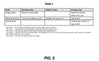
- Exemplary time stamp operations are described in Table 2 of FIG. 5 , as are other exemplary functions that are preferably associated with exemplary method embodiments hereof.
- Table 2 indicates that when a scale becomes empty all existing time stamps should be cleared, and when the vehicle enters the scale (i.e., the scale exits the "empty scale” state) a corresponding time stamp and load cell entry pair output data should be stored.
- Table 2 indicates that the last analysis results should be cleared on vehicle entry, Test Cases 4-5 should be analyzed as the vehicle traverses the scale, and the analysis results should be logged at vehicle exit.
- Table 2 indicates that Test Cases 1-3 should also be analyzed and the results should be logged.
- a processor and associated programming are used to analyze the gross weight reading and load cell or load cell pair output states in method embodiments hereof, and to thereby determine whether the load cells of the scale are operating properly and/or to detect a deliberate manipulation of the load cells.
- the programming may include several algorithms for this purpose, with the algorithms executing on the processor.
- the processor may be a part of a controller, such as a weighing scale controller.
- the weighing scale controller may be in the form of a weigh terminal, such as for example, a model IND780 weigh terminal available from Mettler-Toledo in Columbus, Ohio.
- the load cells may be various types of digital load cells capable of reporting the described information to the controller.
- the load cells may be Powercell® PDX® load cells also available from Mettler-Toledo, and may be arranged as a Powercell PDX network of load cells.
Landscapes
- Physics & Mathematics (AREA)
- General Physics & Mathematics (AREA)
- Motorcycle And Bicycle Frame (AREA)
- Management, Administration, Business Operations System, And Electronic Commerce (AREA)
- Investigating Or Analysing Biological Materials (AREA)
- Warehouses Or Storage Devices (AREA)
- Electric Propulsion And Braking For Vehicles (AREA)
Applications Claiming Priority (1)
| Application Number | Priority Date | Filing Date | Title |
|---|---|---|---|
| US14/137,986 US9194737B2 (en) | 2013-12-20 | 2013-12-20 | Method of determining vehicle scale health and suitability for use via weight transfer pattern analysis |
Publications (3)
| Publication Number | Publication Date |
|---|---|
| EP2889591A2 true EP2889591A2 (de) | 2015-07-01 |
| EP2889591A3 EP2889591A3 (de) | 2015-08-12 |
| EP2889591B1 EP2889591B1 (de) | 2022-07-06 |
Family
ID=52449915
Family Applications (1)
| Application Number | Title | Priority Date | Filing Date |
|---|---|---|---|
| EP14198407.0A Active EP2889591B1 (de) | 2013-12-20 | 2014-12-17 | Verfahren zur Bestimmung der Unversehrtheit einer Fahrzeugwaage und Eignung zur Verwendung über eine Gewichtsübertragungsmusteranalyse |
Country Status (6)
| Country | Link |
|---|---|
| US (1) | US9194737B2 (de) |
| EP (1) | EP2889591B1 (de) |
| CN (1) | CN104748832B (de) |
| BR (1) | BR102014030904B1 (de) |
| CA (1) | CA2873169C (de) |
| DK (1) | DK2889591T3 (de) |
Cited By (1)
| Publication number | Priority date | Publication date | Assignee | Title |
|---|---|---|---|---|
| WO2018162256A1 (de) * | 2017-03-09 | 2018-09-13 | Continental Automotive Gmbh | Verfahren zum betreiben eines fahrzeugeigenen wägesystems und tachographsystem mit einem wägesystem |
Families Citing this family (12)
| Publication number | Priority date | Publication date | Assignee | Title |
|---|---|---|---|---|
| CN105571690B (zh) * | 2014-10-09 | 2018-09-07 | 梅特勒-托利多(常州)精密仪器有限公司 | 数字称重传感器及传感器网络 |
| CN105403298B (zh) * | 2015-12-30 | 2019-04-23 | 福州恒荣信息科技有限公司 | 地磅自动称重方法 |
| WO2020177871A1 (en) * | 2019-03-07 | 2020-09-10 | Volvo Truck Corporation | A method for determining a mass property of a vehicle |
| CN109855710B (zh) * | 2019-03-11 | 2021-04-27 | 耿建航 | 一种汽车衡称重状态监测系统及检测方法 |
| DE102019207276A1 (de) * | 2019-05-17 | 2020-11-19 | Robert Bosch Gmbh | Verwendung einer Lastverteilung eines automatisierten Nutzfahrzeugs für eine situationsbedingt adaptierte Trajektorienplanung und Trajektorienregelung |
| CN112050920B (zh) * | 2020-07-28 | 2022-08-09 | 浙江东鼎电子股份有限公司 | 一种多点组合动态称重检测设备 |
| CN111896092A (zh) * | 2020-08-10 | 2020-11-06 | 南京小牛智能科技有限公司 | 一种自助餐称重计量的防作弊方法 |
| CN111924768B (zh) * | 2020-09-08 | 2023-08-04 | 上海市特种设备监督检验技术研究院 | 一种对叉车驾驶员进行监测和提醒的装置和方法 |
| CN112763037B (zh) * | 2020-12-30 | 2023-06-06 | 北京万集科技股份有限公司 | 称重设备监测系统及其监测方法 |
| CN114235118A (zh) * | 2022-02-24 | 2022-03-25 | 中建电子商务有限责任公司 | 一种基于模块化驱动的现场过磅方法及系统 |
| CN118776650B (zh) * | 2024-09-11 | 2025-02-07 | 杭州企智互联科技有限公司 | 一种智能称重管理系统 |
| CN120270607B (zh) * | 2025-06-03 | 2025-08-22 | 宁波公众信息产业有限公司 | 一种基于主动学习的称重设备控制系统 |
Family Cites Families (14)
| Publication number | Priority date | Publication date | Assignee | Title |
|---|---|---|---|---|
| US3593263A (en) * | 1969-12-04 | 1971-07-13 | Blh Electronics | Apparatus for vehicle direction sensing |
| JPS5323099B2 (de) * | 1973-03-12 | 1978-07-12 | ||
| US3825734A (en) | 1973-03-14 | 1974-07-23 | Reliance Electric Co | Monitor for moving vehicles |
| JPS604413B2 (ja) * | 1975-08-26 | 1985-02-04 | 阪神高速道路公団 | 車両荷重計測装置 |
| JPS62133321A (ja) * | 1985-12-05 | 1987-06-16 | Yamato Scale Co Ltd | 計重コンベヤの動的計重値の補正装置 |
| US4729443A (en) | 1986-12-17 | 1988-03-08 | Colt Industries Inc. | Weighing scale with protection and secondary checking system |
| US4804052A (en) * | 1987-11-30 | 1989-02-14 | Toledo Scale Corporation | Compensated multiple load cell scale |
| CN1031222C (zh) * | 1987-11-30 | 1996-03-06 | 梅特勒-托利多有限公司 | 一种对多测力计秤进行负荷位置补偿的方法 |
| US6576849B2 (en) | 2000-12-01 | 2003-06-10 | Mettler-Toledo, Inc. | Load cell diagnostics and failure prediction weighing apparatus and process |
| US7684946B2 (en) * | 2007-12-17 | 2010-03-23 | Mettler-Toledo, Inc. | Weigh-in-motion system with auto-calibration |
| EP2159554A1 (de) | 2008-08-29 | 2010-03-03 | Mettler-Toledo AG | Verfahren zur Zustandsüberwachung einer Kraftmessvorrichtung, Kraftmessvorrichtung und Kraftmessmodul |
| US8237066B2 (en) * | 2009-12-30 | 2012-08-07 | Mettler-Toledo, LLC | Weighing apparatus employing load cells of different capacity |
| JP5601589B2 (ja) * | 2011-03-31 | 2014-10-08 | 三菱マテリアル株式会社 | 積荷量の不正検出装置 |
| US9638756B2 (en) * | 2012-12-11 | 2017-05-02 | Honeywell International Inc. | Load cell residual fatigue life estimation system and method |
-
2013
- 2013-12-20 US US14/137,986 patent/US9194737B2/en active Active
-
2014
- 2014-12-03 CA CA2873169A patent/CA2873169C/en active Active
- 2014-12-10 BR BR102014030904-7A patent/BR102014030904B1/pt active IP Right Grant
- 2014-12-17 EP EP14198407.0A patent/EP2889591B1/de active Active
- 2014-12-17 DK DK14198407.0T patent/DK2889591T3/da active
- 2014-12-18 CN CN201410790630.3A patent/CN104748832B/zh active Active
Non-Patent Citations (1)
| Title |
|---|
| None |
Cited By (1)
| Publication number | Priority date | Publication date | Assignee | Title |
|---|---|---|---|---|
| WO2018162256A1 (de) * | 2017-03-09 | 2018-09-13 | Continental Automotive Gmbh | Verfahren zum betreiben eines fahrzeugeigenen wägesystems und tachographsystem mit einem wägesystem |
Also Published As
| Publication number | Publication date |
|---|---|
| BR102014030904B1 (pt) | 2021-06-01 |
| US20150177054A1 (en) | 2015-06-25 |
| DK2889591T3 (da) | 2022-10-10 |
| EP2889591A3 (de) | 2015-08-12 |
| CN104748832A (zh) | 2015-07-01 |
| US9194737B2 (en) | 2015-11-24 |
| CA2873169A1 (en) | 2015-06-20 |
| EP2889591B1 (de) | 2022-07-06 |
| CA2873169C (en) | 2022-09-20 |
| BR102014030904A2 (pt) | 2015-10-06 |
| CN104748832B (zh) | 2020-02-11 |
Similar Documents
| Publication | Publication Date | Title |
|---|---|---|
| EP2889591B1 (de) | Verfahren zur Bestimmung der Unversehrtheit einer Fahrzeugwaage und Eignung zur Verwendung über eine Gewichtsübertragungsmusteranalyse | |
| US9864968B2 (en) | Systems and methods for freight tracking and monitoring | |
| US6345228B1 (en) | Road vehicle sensing apparatus and signal processing apparatus therefor | |
| US20100057592A1 (en) | Systems and methods for freight tracking and monitoring | |
| CN107203804B (zh) | 一种数据处理方法、装置及系统 | |
| CN108238538A (zh) | 一种自动扶梯的故障监测方法和故障监测系统 | |
| CN107122943A (zh) | 一种通过测量载重计算运输趟数的系统及方法 | |
| CN110168585A (zh) | 一种数据处理方法、装置及系统 | |
| GB2415268A (en) | Apparatus and method for process monitoring | |
| JP2010210296A (ja) | 車両計量装置 | |
| CN119741836A (zh) | 交通治超系统的智能检测预警方法 | |
| CN116222719B (zh) | 桥梁动态载荷监测系统和方法 | |
| Gupta et al. | Weigh-in-Motion Sensor and Controller Operation and Performance Comparison | |
| JP3185551B2 (ja) | インライン車体計測装置のタクト外計測実行タイミング制御装置 | |
| JP2019194523A (ja) | 計量装置の異常検出装置および異常検出方法 | |
| JP4641193B2 (ja) | 高速計量装置用計量データ処理装置 | |
| CN108460542A (zh) | 一种粮库出入库管理的方法、装置及计算机可读存储介质 | |
| CN115435880A (zh) | 一种双向汽车衡无人值守智能称重方法及系统 | |
| JP2001225914A (ja) | 自動倉庫管理システム | |
| CN106094791A (zh) | 车载控制器及其故障时间获取方法、诊断系统和汽车 | |
| JPH06266634A (ja) | 情報処理装置の保守システム | |
| KR101733087B1 (ko) | 부품 패키징 관리시스템용 패키징 수량 검증장치 | |
| CN116164826B (zh) | 桥梁动态载荷监测系统和方法 | |
| CN121175701A (zh) | 一种检测方法、装置及设备 | |
| NL1028917C2 (nl) | Systeem en werkwijze voor het keuren van magazijnen. |
Legal Events
| Date | Code | Title | Description |
|---|---|---|---|
| PUAI | Public reference made under article 153(3) epc to a published international application that has entered the european phase |
Free format text: ORIGINAL CODE: 0009012 |
|
| 17P | Request for examination filed |
Effective date: 20141217 |
|
| AK | Designated contracting states |
Kind code of ref document: A2 Designated state(s): AL AT BE BG CH CY CZ DE DK EE ES FI FR GB GR HR HU IE IS IT LI LT LU LV MC MK MT NL NO PL PT RO RS SE SI SK SM TR |
|
| AX | Request for extension of the european patent |
Extension state: BA ME |
|
| PUAL | Search report despatched |
Free format text: ORIGINAL CODE: 0009013 |
|
| RIC1 | Information provided on ipc code assigned before grant |
Ipc: G01G 23/01 20060101ALI20150626BHEP Ipc: G01G 19/02 20060101AFI20150626BHEP |
|
| AK | Designated contracting states |
Kind code of ref document: A3 Designated state(s): AL AT BE BG CH CY CZ DE DK EE ES FI FR GB GR HR HU IE IS IT LI LT LU LV MC MK MT NL NO PL PT RO RS SE SI SK SM TR |
|
| AX | Request for extension of the european patent |
Extension state: BA ME |
|
| RIC1 | Information provided on ipc code assigned before grant |
Ipc: G01G 23/01 20060101ALI20150706BHEP Ipc: G01G 19/02 20060101AFI20150706BHEP |
|
| R17P | Request for examination filed (corrected) |
Effective date: 20160209 |
|
| RBV | Designated contracting states (corrected) |
Designated state(s): AL AT BE BG CH CY CZ DE DK EE ES FI FR GB GR HR HU IE IS IT LI LT LU LV MC MK MT NL NO PL PT RO RS SE SI SK SM TR |
|
| STAA | Information on the status of an ep patent application or granted ep patent |
Free format text: STATUS: EXAMINATION IS IN PROGRESS |
|
| 17Q | First examination report despatched |
Effective date: 20180910 |
|
| RIN1 | Information on inventor provided before grant (corrected) |
Inventor name: BLISS, DOUGLAS |
|
| GRAP | Despatch of communication of intention to grant a patent |
Free format text: ORIGINAL CODE: EPIDOSNIGR1 |
|
| STAA | Information on the status of an ep patent application or granted ep patent |
Free format text: STATUS: GRANT OF PATENT IS INTENDED |
|
| INTG | Intention to grant announced |
Effective date: 20220425 |
|
| GRAS | Grant fee paid |
Free format text: ORIGINAL CODE: EPIDOSNIGR3 |
|
| GRAA | (expected) grant |
Free format text: ORIGINAL CODE: 0009210 |
|
| STAA | Information on the status of an ep patent application or granted ep patent |
Free format text: STATUS: THE PATENT HAS BEEN GRANTED |
|
| AK | Designated contracting states |
Kind code of ref document: B1 Designated state(s): AL AT BE BG CH CY CZ DE DK EE ES FI FR GB GR HR HU IE IS IT LI LT LU LV MC MK MT NL NO PL PT RO RS SE SI SK SM TR |
|
| REG | Reference to a national code |
Ref country code: GB Ref legal event code: FG4D |
|
| REG | Reference to a national code |
Ref country code: AT Ref legal event code: REF Ref document number: 1503167 Country of ref document: AT Kind code of ref document: T Effective date: 20220715 Ref country code: CH Ref legal event code: EP |
|
| REG | Reference to a national code |
Ref country code: DE Ref legal event code: R096 Ref document number: 602014084211 Country of ref document: DE |
|
| REG | Reference to a national code |
Ref country code: IE Ref legal event code: FG4D |
|
| REG | Reference to a national code |
Ref country code: DK Ref legal event code: T3 Effective date: 20221006 Ref country code: NO Ref legal event code: T2 Effective date: 20220706 |
|
| REG | Reference to a national code |
Ref country code: SE Ref legal event code: TRGR Ref country code: LT Ref legal event code: MG9D |
|
| REG | Reference to a national code |
Ref country code: NL Ref legal event code: MP Effective date: 20220706 |
|
| PG25 | Lapsed in a contracting state [announced via postgrant information from national office to epo] |
Ref country code: RS Free format text: LAPSE BECAUSE OF FAILURE TO SUBMIT A TRANSLATION OF THE DESCRIPTION OR TO PAY THE FEE WITHIN THE PRESCRIBED TIME-LIMIT Effective date: 20220706 Ref country code: PT Free format text: LAPSE BECAUSE OF FAILURE TO SUBMIT A TRANSLATION OF THE DESCRIPTION OR TO PAY THE FEE WITHIN THE PRESCRIBED TIME-LIMIT Effective date: 20221107 Ref country code: NL Free format text: LAPSE BECAUSE OF FAILURE TO SUBMIT A TRANSLATION OF THE DESCRIPTION OR TO PAY THE FEE WITHIN THE PRESCRIBED TIME-LIMIT Effective date: 20220706 Ref country code: LV Free format text: LAPSE BECAUSE OF FAILURE TO SUBMIT A TRANSLATION OF THE DESCRIPTION OR TO PAY THE FEE WITHIN THE PRESCRIBED TIME-LIMIT Effective date: 20220706 Ref country code: LT Free format text: LAPSE BECAUSE OF FAILURE TO SUBMIT A TRANSLATION OF THE DESCRIPTION OR TO PAY THE FEE WITHIN THE PRESCRIBED TIME-LIMIT Effective date: 20220706 Ref country code: FI Free format text: LAPSE BECAUSE OF FAILURE TO SUBMIT A TRANSLATION OF THE DESCRIPTION OR TO PAY THE FEE WITHIN THE PRESCRIBED TIME-LIMIT Effective date: 20220706 Ref country code: ES Free format text: LAPSE BECAUSE OF FAILURE TO SUBMIT A TRANSLATION OF THE DESCRIPTION OR TO PAY THE FEE WITHIN THE PRESCRIBED TIME-LIMIT Effective date: 20220706 |
|
| REG | Reference to a national code |
Ref country code: AT Ref legal event code: MK05 Ref document number: 1503167 Country of ref document: AT Kind code of ref document: T Effective date: 20220706 |
|
| PG25 | Lapsed in a contracting state [announced via postgrant information from national office to epo] |
Ref country code: PL Free format text: LAPSE BECAUSE OF FAILURE TO SUBMIT A TRANSLATION OF THE DESCRIPTION OR TO PAY THE FEE WITHIN THE PRESCRIBED TIME-LIMIT Effective date: 20220706 Ref country code: IS Free format text: LAPSE BECAUSE OF FAILURE TO SUBMIT A TRANSLATION OF THE DESCRIPTION OR TO PAY THE FEE WITHIN THE PRESCRIBED TIME-LIMIT Effective date: 20221106 Ref country code: HR Free format text: LAPSE BECAUSE OF FAILURE TO SUBMIT A TRANSLATION OF THE DESCRIPTION OR TO PAY THE FEE WITHIN THE PRESCRIBED TIME-LIMIT Effective date: 20220706 Ref country code: GR Free format text: LAPSE BECAUSE OF FAILURE TO SUBMIT A TRANSLATION OF THE DESCRIPTION OR TO PAY THE FEE WITHIN THE PRESCRIBED TIME-LIMIT Effective date: 20221007 |
|
| REG | Reference to a national code |
Ref country code: DE Ref legal event code: R097 Ref document number: 602014084211 Country of ref document: DE |
|
| PG25 | Lapsed in a contracting state [announced via postgrant information from national office to epo] |
Ref country code: SM Free format text: LAPSE BECAUSE OF FAILURE TO SUBMIT A TRANSLATION OF THE DESCRIPTION OR TO PAY THE FEE WITHIN THE PRESCRIBED TIME-LIMIT Effective date: 20220706 Ref country code: RO Free format text: LAPSE BECAUSE OF FAILURE TO SUBMIT A TRANSLATION OF THE DESCRIPTION OR TO PAY THE FEE WITHIN THE PRESCRIBED TIME-LIMIT Effective date: 20220706 Ref country code: CZ Free format text: LAPSE BECAUSE OF FAILURE TO SUBMIT A TRANSLATION OF THE DESCRIPTION OR TO PAY THE FEE WITHIN THE PRESCRIBED TIME-LIMIT Effective date: 20220706 Ref country code: AT Free format text: LAPSE BECAUSE OF FAILURE TO SUBMIT A TRANSLATION OF THE DESCRIPTION OR TO PAY THE FEE WITHIN THE PRESCRIBED TIME-LIMIT Effective date: 20220706 |
|
| PLBE | No opposition filed within time limit |
Free format text: ORIGINAL CODE: 0009261 |
|
| STAA | Information on the status of an ep patent application or granted ep patent |
Free format text: STATUS: NO OPPOSITION FILED WITHIN TIME LIMIT |
|
| PG25 | Lapsed in a contracting state [announced via postgrant information from national office to epo] |
Ref country code: SK Free format text: LAPSE BECAUSE OF FAILURE TO SUBMIT A TRANSLATION OF THE DESCRIPTION OR TO PAY THE FEE WITHIN THE PRESCRIBED TIME-LIMIT Effective date: 20220706 Ref country code: EE Free format text: LAPSE BECAUSE OF FAILURE TO SUBMIT A TRANSLATION OF THE DESCRIPTION OR TO PAY THE FEE WITHIN THE PRESCRIBED TIME-LIMIT Effective date: 20220706 |
|
| 26N | No opposition filed |
Effective date: 20230411 |
|
| PG25 | Lapsed in a contracting state [announced via postgrant information from national office to epo] |
Ref country code: AL Free format text: LAPSE BECAUSE OF FAILURE TO SUBMIT A TRANSLATION OF THE DESCRIPTION OR TO PAY THE FEE WITHIN THE PRESCRIBED TIME-LIMIT Effective date: 20220706 |
|
| REG | Reference to a national code |
Ref country code: CH Ref legal event code: PL |
|
| GBPC | Gb: european patent ceased through non-payment of renewal fee |
Effective date: 20221217 |
|
| PG25 | Lapsed in a contracting state [announced via postgrant information from national office to epo] |
Ref country code: SI Free format text: LAPSE BECAUSE OF FAILURE TO SUBMIT A TRANSLATION OF THE DESCRIPTION OR TO PAY THE FEE WITHIN THE PRESCRIBED TIME-LIMIT Effective date: 20220706 Ref country code: LU Free format text: LAPSE BECAUSE OF NON-PAYMENT OF DUE FEES Effective date: 20221217 |
|
| PG25 | Lapsed in a contracting state [announced via postgrant information from national office to epo] |
Ref country code: LI Free format text: LAPSE BECAUSE OF NON-PAYMENT OF DUE FEES Effective date: 20221231 Ref country code: IE Free format text: LAPSE BECAUSE OF NON-PAYMENT OF DUE FEES Effective date: 20221217 Ref country code: GB Free format text: LAPSE BECAUSE OF NON-PAYMENT OF DUE FEES Effective date: 20221217 Ref country code: CH Free format text: LAPSE BECAUSE OF NON-PAYMENT OF DUE FEES Effective date: 20221231 |
|
| PG25 | Lapsed in a contracting state [announced via postgrant information from national office to epo] |
Ref country code: IT Free format text: LAPSE BECAUSE OF FAILURE TO SUBMIT A TRANSLATION OF THE DESCRIPTION OR TO PAY THE FEE WITHIN THE PRESCRIBED TIME-LIMIT Effective date: 20220706 |
|
| PG25 | Lapsed in a contracting state [announced via postgrant information from national office to epo] |
Ref country code: HU Free format text: LAPSE BECAUSE OF FAILURE TO SUBMIT A TRANSLATION OF THE DESCRIPTION OR TO PAY THE FEE WITHIN THE PRESCRIBED TIME-LIMIT; INVALID AB INITIO Effective date: 20141217 |
|
| PG25 | Lapsed in a contracting state [announced via postgrant information from national office to epo] |
Ref country code: CY Free format text: LAPSE BECAUSE OF FAILURE TO SUBMIT A TRANSLATION OF THE DESCRIPTION OR TO PAY THE FEE WITHIN THE PRESCRIBED TIME-LIMIT Effective date: 20220706 |
|
| PG25 | Lapsed in a contracting state [announced via postgrant information from national office to epo] |
Ref country code: MK Free format text: LAPSE BECAUSE OF FAILURE TO SUBMIT A TRANSLATION OF THE DESCRIPTION OR TO PAY THE FEE WITHIN THE PRESCRIBED TIME-LIMIT Effective date: 20220706 |
|
| PG25 | Lapsed in a contracting state [announced via postgrant information from national office to epo] |
Ref country code: MC Free format text: LAPSE BECAUSE OF FAILURE TO SUBMIT A TRANSLATION OF THE DESCRIPTION OR TO PAY THE FEE WITHIN THE PRESCRIBED TIME-LIMIT Effective date: 20220706 |
|
| PG25 | Lapsed in a contracting state [announced via postgrant information from national office to epo] |
Ref country code: MC Free format text: LAPSE BECAUSE OF FAILURE TO SUBMIT A TRANSLATION OF THE DESCRIPTION OR TO PAY THE FEE WITHIN THE PRESCRIBED TIME-LIMIT Effective date: 20220706 |
|
| PG25 | Lapsed in a contracting state [announced via postgrant information from national office to epo] |
Ref country code: BG Free format text: LAPSE BECAUSE OF FAILURE TO SUBMIT A TRANSLATION OF THE DESCRIPTION OR TO PAY THE FEE WITHIN THE PRESCRIBED TIME-LIMIT Effective date: 20220706 |
|
| PG25 | Lapsed in a contracting state [announced via postgrant information from national office to epo] |
Ref country code: MT Free format text: LAPSE BECAUSE OF FAILURE TO SUBMIT A TRANSLATION OF THE DESCRIPTION OR TO PAY THE FEE WITHIN THE PRESCRIBED TIME-LIMIT Effective date: 20220706 |
|
| PG25 | Lapsed in a contracting state [announced via postgrant information from national office to epo] |
Ref country code: TR Free format text: LAPSE BECAUSE OF FAILURE TO SUBMIT A TRANSLATION OF THE DESCRIPTION OR TO PAY THE FEE WITHIN THE PRESCRIBED TIME-LIMIT Effective date: 20220706 |
|
| PGFP | Annual fee paid to national office [announced via postgrant information from national office to epo] |
Ref country code: NO Payment date: 20251218 Year of fee payment: 12 |
|
| PGFP | Annual fee paid to national office [announced via postgrant information from national office to epo] |
Ref country code: DK Payment date: 20251222 Year of fee payment: 12 |
|
| PGFP | Annual fee paid to national office [announced via postgrant information from national office to epo] |
Ref country code: FR Payment date: 20251223 Year of fee payment: 12 |
|
| PGFP | Annual fee paid to national office [announced via postgrant information from national office to epo] |
Ref country code: SE Payment date: 20251222 Year of fee payment: 12 |
|
| PGFP | Annual fee paid to national office [announced via postgrant information from national office to epo] |
Ref country code: DE Payment date: 20251229 Year of fee payment: 12 |
|
| PGFP | Annual fee paid to national office [announced via postgrant information from national office to epo] |
Ref country code: BE Payment date: 20260109 Year of fee payment: 12 |