EP2889502B1 - Kugellager - Google Patents
Kugellager Download PDFInfo
- Publication number
- EP2889502B1 EP2889502B1 EP14200290.6A EP14200290A EP2889502B1 EP 2889502 B1 EP2889502 B1 EP 2889502B1 EP 14200290 A EP14200290 A EP 14200290A EP 2889502 B1 EP2889502 B1 EP 2889502B1
- Authority
- EP
- European Patent Office
- Prior art keywords
- oil
- axial
- annular portion
- ball bearing
- ring
- Prior art date
- Legal status (The legal status is an assumption and is not a legal conclusion. Google has not performed a legal analysis and makes no representation as to the accuracy of the status listed.)
- Not-in-force
Links
Images




Classifications
-
- F—MECHANICAL ENGINEERING; LIGHTING; HEATING; WEAPONS; BLASTING
- F16—ENGINEERING ELEMENTS AND UNITS; GENERAL MEASURES FOR PRODUCING AND MAINTAINING EFFECTIVE FUNCTIONING OF MACHINES OR INSTALLATIONS; THERMAL INSULATION IN GENERAL
- F16C—SHAFTS; FLEXIBLE SHAFTS; ELEMENTS OR CRANKSHAFT MECHANISMS; ROTARY BODIES OTHER THAN GEARING ELEMENTS; BEARINGS
- F16C33/00—Parts of bearings; Special methods for making bearings or parts thereof
- F16C33/30—Parts of ball or roller bearings
- F16C33/66—Special parts or details in view of lubrication
- F16C33/6637—Special parts or details in view of lubrication with liquid lubricant
- F16C33/6681—Details of distribution or circulation inside the bearing, e.g. grooves on the cage or passages in the rolling elements
-
- F—MECHANICAL ENGINEERING; LIGHTING; HEATING; WEAPONS; BLASTING
- F16—ENGINEERING ELEMENTS AND UNITS; GENERAL MEASURES FOR PRODUCING AND MAINTAINING EFFECTIVE FUNCTIONING OF MACHINES OR INSTALLATIONS; THERMAL INSULATION IN GENERAL
- F16C—SHAFTS; FLEXIBLE SHAFTS; ELEMENTS OR CRANKSHAFT MECHANISMS; ROTARY BODIES OTHER THAN GEARING ELEMENTS; BEARINGS
- F16C19/00—Bearings with rolling contact, for exclusively rotary movement
- F16C19/02—Bearings with rolling contact, for exclusively rotary movement with bearing balls essentially of the same size in one or more circular rows
- F16C19/14—Bearings with rolling contact, for exclusively rotary movement with bearing balls essentially of the same size in one or more circular rows for both radial and axial load
- F16C19/18—Bearings with rolling contact, for exclusively rotary movement with bearing balls essentially of the same size in one or more circular rows for both radial and axial load with two or more rows of balls
- F16C19/181—Bearings with rolling contact, for exclusively rotary movement with bearing balls essentially of the same size in one or more circular rows for both radial and axial load with two or more rows of balls with angular contact
- F16C19/182—Bearings with rolling contact, for exclusively rotary movement with bearing balls essentially of the same size in one or more circular rows for both radial and axial load with two or more rows of balls with angular contact in tandem arrangement
-
- F—MECHANICAL ENGINEERING; LIGHTING; HEATING; WEAPONS; BLASTING
- F16—ENGINEERING ELEMENTS AND UNITS; GENERAL MEASURES FOR PRODUCING AND MAINTAINING EFFECTIVE FUNCTIONING OF MACHINES OR INSTALLATIONS; THERMAL INSULATION IN GENERAL
- F16C—SHAFTS; FLEXIBLE SHAFTS; ELEMENTS OR CRANKSHAFT MECHANISMS; ROTARY BODIES OTHER THAN GEARING ELEMENTS; BEARINGS
- F16C33/00—Parts of bearings; Special methods for making bearings or parts thereof
- F16C33/30—Parts of ball or roller bearings
- F16C33/38—Ball cages
- F16C33/40—Ball cages for multiple rows of balls
- F16C33/405—Ball cages for multiple rows of balls with two or more juxtaposed cages joined together or interacting with each other
-
- F—MECHANICAL ENGINEERING; LIGHTING; HEATING; WEAPONS; BLASTING
- F16—ENGINEERING ELEMENTS AND UNITS; GENERAL MEASURES FOR PRODUCING AND MAINTAINING EFFECTIVE FUNCTIONING OF MACHINES OR INSTALLATIONS; THERMAL INSULATION IN GENERAL
- F16C—SHAFTS; FLEXIBLE SHAFTS; ELEMENTS OR CRANKSHAFT MECHANISMS; ROTARY BODIES OTHER THAN GEARING ELEMENTS; BEARINGS
- F16C33/00—Parts of bearings; Special methods for making bearings or parts thereof
- F16C33/30—Parts of ball or roller bearings
- F16C33/66—Special parts or details in view of lubrication
- F16C33/6637—Special parts or details in view of lubrication with liquid lubricant
- F16C33/6659—Details of supply of the liquid to the bearing, e.g. passages or nozzles
- F16C33/6674—Details of supply of the liquid to the bearing, e.g. passages or nozzles related to the amount supplied, e.g. gaps to restrict flow of the liquid
Definitions
- the invention relates to a ball bearing that is lubricated by oil.
- a rolling bearing is used to support a rotary shaft of a rotation portion included in a vehicle, a machine tool, or the like, and a ball bearing is known as the rolling bearing.
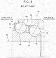
- FIG. 8 is a sectional view of a double row angular contact ball bearing 99 that supports a rotary shaft 94.
- the ball bearing 99 includes an outer ring 98, an inner ring 97, balls 96 disposed in double rows, and a cage 95 that retains the balls 96 in each row at intervals in a circumferential direction.
- the ball bearing 99 is lubricated by oil around the ball bearing 99.
- the ball bearing 99 is described in, for example, Japanese patent application publication No. 2010-7788 .
- the pumping action may be caused in a single row angular contact ball bearing, as well as in a double row angular contact ball bearing. Further, even in the case where the balls do not make angular contact with the inner ring and the outer ring, the pumping action may be caused depending on the shape of an inner peripheral surface of the outer ring, or the shape of an outer peripheral surface of the inner ring, or the pumping action may be caused by the rotation of the cage. In the ball bearing described in Japanese Patent Application Publication No. 2010-7788 , the size of an annular portion positioned on an oil inflow side in the cage is increased to reduce a clearance between the inner ring and the outer ring, and to reduce the inflow of the oil.
- the invention provides a ball bearing according to claim 1 that reduces inflow of oil into a bearing inner area.
- a ball bearing according to a first aspect includes an outer ring; an inner ring; a plurality of balls disposed between the outer ring and the inner ring; and a cage that has an annular shape, and retains the balls at intervals in a circumferential direction. Oil flows into an area between the outer ring and the inner ring from one side in an axial direction and flows out from the other side in the axial direction.
- the cage includes an annular portion provided on an oil inflow side, and bar portions extending from the annular portion toward an oil outflow side.
- An outer peripheral end portion of the annular portion is constituted by a corner portion at which an axial outer end face of the annular portion intersects with an outer peripheral surface of the annular portion.
- An axial position of a tip end of the corner portion is substantially same as an axial position of a side surface of the outer ring.
- the outer peripheral end portion of the annular portion on the oil inflow side in the cage is constituted by the corner portion at which the axial outer end face of the annular portion intersects with the outer peripheral surface of the annular portion.
- the oil flows toward the outer side in the radial direction, along the axial outer end face of the annular portion due to the centrifugal force caused by the rotation of the ball bearing.
- the oil passes by the corner portion, the oil flows away from the corner portion, and a low pressure region is formed at the back of the corner portion.
- An oil passage is formed in a space (an outer peripheral clearance) between the outer peripheral surface of the annular portion and the inner peripheral surface of the outer ring.
- the axial position of the tip end of the corner portion is substantially the same as the axial position of the side surface of the outer ring, and therefore, the low pressure region is formed at an inlet portion (an axial outer portion) of the oil passage.
- the oil is unlikely to flow in a direction from the inlet portion (the axial outer portion) of the oil passage to the inner area of the ball bearing.
- it is possible to reduce the inflow of the oil into the inner area of the ball bearing through the outer peripheral clearance.
- a ball bearing according to a second aspect includes an outer ring; an inner ring; a plurality of balls disposed between the outer ring and the inner ring; and a cage that has an annular shape, and retains the balls at intervals in a circumferential direction.
- Oil flows into an area between the outer ring and the inner ring from one side in an axial direction and flows out from the other side in the axial direction.
- the cage includes an annular portion provided on an oil inflow side, and bar portions extending from the annular portion toward an oil outflow side.
- An outer peripheral end portion of the annular portion is constituted by a corner portion at which an axial outer end face of the annular portion intersects with an outer peripheral surface of the annular portion.
- An axial position of a tip end of the corner portion is outside an axial position of a side surface of the outer ring in the axial direction.
- the outer peripheral end portion of the annular portion on the oil inflow side in the cage is constituted by the corner portion at which the axial outer end face of the annular portion intersects with the outer peripheral surface of the annular portion.
- the oil flows toward the outer side in the radial direction, along the axial outer end face of the annular portion due to the centrifugal force caused by the rotation of the ball bearing.
- the oil passes by the corner portion, the oil flows away from the corner portion, and a low pressure region is formed at the back of the corner portion.
- An oil passage is formed in a space (an outer peripheral clearance) between the outer peripheral surface of the annular portion and the inner peripheral surface of the outer ring.
- the axial position of the tip end of the corner portion is outside the axial position of the side surface of the outer ring in the axial direction, and therefore, the oil that has flowed away from the corner portion is unlikely to reach an inlet portion (an axial outer portion) of the oil passage, and the low pressure region is formed at the inlet portion (the axial outer portion) of the oil passage.
- the oil is unlikely to flow in a direction from the inlet portion (the axial outer portion) of the oil passage to the inner area of the ball bearing.
- the axial outer end face of the annular portion may include an outer inclined surface that is inclined toward an axial outer side in a direction toward a radial outer side.
- the oil which has flowed along the outer inclined surface of the annular portion, and flowed away from the corner portion, is unlikely to reach the inlet portion (the axial outer portion) of the oil passage, and thus, it is possible to reduce the inflow of the oil into the inner area of the ball bearing.
- the outer peripheral end portion of the annular portion may be constituted by the corner portion at which the outer peripheral surface of the annular portion intersects with the outer inclined surface at an acute angle. In this case, when the oil passes by the corner portion, the oil flows away from the corner portion easily, and thus, the low pressure region is stably formed.
- the outer ring may include an annular main body and a protruding portion that is provided at a position facing the outer peripheral surface of the annular portion such that the protruding portion protrudes from the annular main body; and a raceway surface, on which the balls roll, may be provided in an inner peripheral side of the annular main body.
- the cage may be easily produced.
- the side surface of the outer ring whose axial position is compared with the axial position of the tip end of the corner portion as described above, is the axial outer side surface of the protruding portion.
- the outer peripheral surface of the annular portion may have a cylindrical surface whose center axis is an axis of the cage and the outer ring, and an inner peripheral surface of a portion of the outer ring may have a cylindrical surface whose center axis is the axis of the cage and the outer ring, the inner peripheral surface of the portion of the outer ring facing the outer peripheral surface of the annular portion.
- the oil passage with a cylindrical shape is formed in the space (the outer peripheral clearance) between the outer peripheral surface of the annular portion and the inner peripheral surface of the portion of the outer ring.
- the axial position of the tip end of the corner portion is substantially the same as, or outside the axial position of the side surface of the outer ring in the axial direction. Therefore, the low pressure region is formed at the inlet portion (the axial outer portion) of the cylindrical oil passage. Since the outer peripheral surface of the annular portion, which forms the cylindrical oil passage, is a cylindrical surface whose center axis is the axis of the cage. Therefore, the oil on the cylindrical surface flows toward the outer side in the radial direction due to the centrifugal force, but the oil is unlikely to flow in the axial direction. As described above, the low pressure region is formed at the inlet portion (the axial outer portion) of the cylindrical oil passage. As a result, the oil is more unlikely to flow from the inlet portion (the axial outer portion) of the cylindrical oil passage toward the inner area of the ball bearing.
- An axial position of an inner peripheral end portion of the annular portion may be inside an axial position of a side surface of the inner ring in the axial direction.
- the oil having a velocity component toward the radial outer side flows along the side surface of the inner ring due to the centrifugal force caused by the rotation of the ball bearing.
- part of the oil flows toward the inner side in the axial direction.
- the axial position of the inner peripheral end portion of the annular portion on the oil inflow side in the cage is inside the axial position of the side surface of the inner ring, the part of the oil flows along the axial outer end face of the annular portion.
- a ball bearing according to a third aspect includes an outer ring; an inner ring; a plurality of balls disposed between the outer ring and the inner ring; and a cage that has an annular shape, and retains the balls at intervals in a circumferential direction. Oil flows into an area between the outer ring and the inner ring from one side in an axial direction and flows out from the other side in the axial direction.
- the cage includes an annular portion provided on an oil inflow side, and bar portions extending from the annular portion toward an oil outflow side. An axial position of an inner peripheral end portion of the annular portion is inside an axial position of a side surface of the inner ring in the axial direction.
- the oil having a velocity component toward the radial outer side flows along the side surface of the inner ring due to the centrifugal force caused by the rotation of the ball bearing.
- part of the oil flows toward the inner side in the axial direction.
- the axial position of the inner peripheral end portion of the annular portion on the oil inflow side in the cage is inside the axial position of the side surface of the inner ring in the axial direction. Therefore, the part of the oil flows along the axial outer end face of the annular portion. Accordingly, it is possible to guide the oil toward the outer side in the radial direction, and to reduce the inflow of the oil into the bearing inner area. If the flow of the oil collides with the cage, and is blocked, pressure increases in the region where the collision occurs.
- the oil in the region where the pressure has increased is likely to flow into the inner area of the ball bearing through the cylindrical space, in which the pressure is relatively low, between the outer peripheral surface of the inner ring and the inner peripheral surface of the annular portion.
- the oil flows along the axial outer end face of the annular portion. Therefore, the flow of the oil is unlikely to be blocked by the cage (the annular portion). As a result, it is possible to reduce the flow of the oil into the inner area of the ball bearing.
- the axial outer end face of the annular portion may include an inner inclined surface that is inclined toward an axial inner side in a direction toward a radial outer side.
- the oil having a velocity component toward the radial outer side flows along the side surface of the inner ring due to the centrifugal force caused by the rotation of the ball bearing.
- the axial outer end face of the annular portion on the oil inflow side in the cage includes the inner inclined surface that is inclined toward the axial inner side in the direction toward the radial outer side. Therefore, the part of the oil flows along the inner inclined surface of the annular portion, and is guided toward the outer side in the radial direction.
- the ball bearing that reduces the inflow of the oil into the bearing inner area so as to reduce the resistance to stirring of the oil and to reduce the torque during the rotation of the ball bearing.
- FIG. 1 is a sectional view illustrating a ball bearing according to an embodiment
- FIG. 2 is an enlarged view of a main portion of the ball bearing shown in FIG. 1
- FIG. 3 is a graph showing results of calculation on flow rate characteristics in an inner peripheral clearance
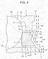
- FIG. 4 is an enlarged view of a main portion of a ball bearing according to a modified embodiment
- FIG. 5 is a graph showing a result of calculation on an amount (flow rate) of oil passing through a cylindrical space
- FIG. 6 is an explanatory view illustrating the case where a rounded surface is provided between a side surface of an outer ring and an inner peripheral cylindrical surface of the outer ring;
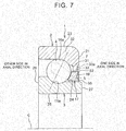
- FIG. 7 is a sectional view illustrating a ball bearing according to another embodiment; and
- FIG. 8 is a sectional view of a ball bearing in related art.
- the ball bearing 1 is a double row angular contact ball bearing.
- the ball bearing 1 includes an outer ring 2 having outer raceway surfaces 16a, 16b provided on an inner periphery thereof; an inner ring 3 having inner raceway surfaces 11a, 11b provided on outer periphery thereof; a plurality of balls 4 that are rollably disposed between the outer raceway surface 16a and the inner raceway surface 11a on one side in an axial direction (a right side in FIG. 1 ); a plurality of balls 4 that are rollably disposed between the outer raceway surface 16b and the inner raceway surface 11b on the other side in the axial direction (a left side in FIG. 1 ); a cage 17 that retains the balls 4 included in a row on the one side in the axial direction such that the balls 4 are retained at equal intervals in a circumferential direction; and a cage 18 that retains the balls 4 included
- Each of the outer ring 2, the inner ring 3, and the cages 17, 18 has an annular shape (a cylindrical shape) whose center axis is a common axis C, in each embodiment described below.
- An outer peripheral surface 23 of the outer ring 2 has a cylindrical shape.
- Each of the outer raceway surfaces 16a, 16b has an arc shape.
- the outer raceway surface 16a on the one side in the axial direction is continuous with an inner peripheral cylindrical surface 31 of a shoulder portion that is formed coaxially with the axis C.
- the diameter of the outer raceway surface 16a is smaller than the diameter of the outer raceway surface 16b.
- the diameter of the inner peripheral surface of the outer ring 2 increases from the one side in the axial direction toward the other side in the axial direction.
- the diameter of each of the outer raceway surfaces 16a, 16b increases from the one side toward the other side in the axial direction.
- the outer ring 2 includes an annular main body 32, and a protruding portion 33 that protrudes toward an inner side in the radial direction from an end portion of the annular main body 32 on the one side in the axial direction.
- the outer raceway surfaces 16a, 16b, on which the balls 4 roll, are provided in the inner peripheral side of the annular main body 32.
- the outer ring 2 is produced using a bearing steel. After a quenching process is performed, finishing is performed on the outer ring 2, by performing a grinding process on each surface of the outer ring 2.
- An inner peripheral surface 25 of the inner ring 3 has a cylindrical shape.
- Each of the inner raceway surfaces 11a, 11b has an arc shape.
- the inner raceway surface 11a on the one side in the axial direction is continuous with the cylindrical surface 24.
- the diameter of the inner raceway surface 11a is smaller than the diameter of the inner raceway surface 11b.
- the diameter of the outer peripheral surface of the inner ring 3 increases from the one side in the axial direction toward the other side in the axial direction.
- the inner ring 3 is produced using a bearing steel. After a quenching process is performed, finishing is performed on the inner ring 3 by performing a grinding process on each surface of the inner ring 3.
- each of the cages 17, 18 includes an annular portion 5 with a smaller diameter, an annular portion 6 with a larger diameter, and a plurality of bar portions 7 that are disposed at equal intervals in the circumferential direction and connect the annular portions 5, 6.
- Each of the cages 17, 18 is produced by injection molding using a synthetic resin such as polyphenylene sulfide or polyamide.
- Each space, which is provided between the annular portions 5, 6 and between the bar portions 7 adjacent to each other in the circumferential direction, is a pocket in which one ball 4 is retained.
- Each of the cages 17, 18 is positioned in the radial direction and the axial direction, when the pockets contact the balls 4. Thus, each of the cages 17, 18 is disposed close to the balls 4 so as to be positioned.
- the cage 17 is guided by the balls 4 to revolve, and thus, the cage 17 is rotated coaxially with the inner ring 3.
- the diameter of the inner peripheral surface of the outer ring 2 increases from the one side toward the other side in the axial direction. Accordingly, as described later, when the ball bearing 1 (the inner ring 3) is rotated, oil flows through an annular space provided between the outer ring 2 and the inner ring 3, from the one side toward the other side in the axial direction, that is, a pumping action is caused.
- the shape of the annular portion 5 on the small-diameter side in the cage 17 on the one side in the axial direction (the right side in FIG. 1 ) will be described with reference to FIG. 2 .
- the annular portion 5 is an annular portion on an oil inflow side into which the oil flows due to pumping action.
- the bar portions 7 extend from the annular portion 5 provided on the oil inflow side toward an oil outflow side.
- the cage 18 on the other side in the axial direction may have the same configuration as the configuration in related art.
- an outer peripheral cylindrical surface 51 is provided at the outer periphery of the annular portion 5.
- the outer peripheral cylindrical surface 51 is continuous with the outer peripheral surface of each bar portion 7.
- the outer peripheral cylindrical surface 51 is disposed coaxially with an inner peripheral cylindrical surface 31 provided at the inner periphery of the outer ring 2.
- the outer peripheral cylindrical surface 51 is disposed coaxially with an inner peripheral surface 34 of the protruding portion 33.
- the inner peripheral surface 34 is constituted by a cylindrical surface that is coaxial with the axis C.
- the protruding portion 33 is provided at a position facing the outer peripheral cylindrical surface 51 (the outer peripheral surface) of the annular portion 5 such that the protruding portion 33 protrudes from the annular main body 32. Therefore, the outer peripheral cylindrical surface 51 and the inner peripheral surface 34 of the protruding portion 33 face each other in the radial direction such that a predetermined clearance is provided between the outer peripheral cylindrical surface 51 and the inner peripheral surface 34.
- a cylindrical space R which is parallel to the axis C, is provided between the outer peripheral cylindrical surface 51 and the inner peripheral surface 34.
- An end face 19 of the annular portion 5 on an outer side in the axial direction (hereinafter, may be referred to as "axial outer end face 19") includes an outer inclined surface 45 that is provided in an outer region of the end face 19 in the radial direction.
- the outer inclined surface 45 is inclined toward an axial outer side in a direction toward a radial outer side (i.e., the outer inclined surface 45 is inclined toward an outer side in the axial direction as the outer inclined surface 45 extends toward an outer side in the radial direction).
- the outer inclined surface 45 is a conical surface that intersects with the outer peripheral cylindrical surface 51 at an acute angle in a section including the axis C. Therefore, an outer peripheral end portion of the annular portion 5 is constituted by a corner portion 52 at which the outer inclined surface 45 intersects with the outer peripheral cylindrical surface 51 at the acute angle.
- the axial position of the tip end of the corner portion 52 substantially coincides with the axial position of the side surface of the outer ring 2, the side surface of the outer ring 2 being located radially outside the tip end of the corner portion 52 to be close to the tip end of the corner portion 52.
- the side surface of the outer ring 2 which is located radially outside the tip end of the corner portion 52 to be close to the tip end of the corner portion 52, is a side surface (i.e., an axial outer side surface) 33a of the protruding portion 33 on the outer side in the axial direction.
- the axial position of the tip end of the corner portion 52 is substantially the same as the axial position of the side surface 33a of the protruding portion 33 of the outer ring 2.
- the positional relation between the annular portion 5 (the outer inclined surface 45) and the outer ring 2 will be described in detail later.
- the configuration in the case where the outer ring 2 does not include the protruding portion 33 will be described using FIG. 2 , although this configuration is not shown in the figure.
- the side surface of the outer ring 2 which is located radially outside the tip end of the corner portion 52 to be close to the tip end of the corner portion 52, is a large end face 21 that is an end face of the outer ring 2 in the axial direction. Accordingly, in this case, the ball bearing 1 is configured such that the axial position of the tip end of the corner portion 52 is substantially the same as the axial position of the large end face 21 of the outer ring 2.
- the axial outer end face 19 of the annular portion 5 includes an inner inclined surface 46 that is provided in an inner region of the end face 19 in the radial direction.
- the inner inclined surface 46 is inclined toward an axial inner side in a direction toward a radial outer side (i.e., the inner inclined surface 46 is inclined toward the inner side in the axial direction as the inner inclined surface 46 extends toward the outer side in the radial direction).
- the inner inclined surface 46 is a conical surface that intersects with the inner peripheral surface 53 of the annular portion 5 having a cylindrical shape, at an acute angle in the section including the axis C. Therefore, an inner peripheral end portion of the annular portion 5 is constituted by a corner portion 55 at which the inner inclined surface 46 intersects with the inner peripheral surface 53 at the acute angle.
- the tip end of the corner portion 55 is provided at a position inside a small end face 27 that is a side surface of the inner ring 3 in the axial direction.
- the corner portion 55 is provided close to the cylindrical surface 24 in the outer peripheral surface of the inner ring 3.
- the axial outer end face 19 of the annular portion 5 includes the inner inclined surface 46 that is provided in the inner region of the end face 19 in the radial direction.
- the inner inclined surface 46 extends from the inner peripheral end portion (the corner portion 55) of the annular portion 5 to be inclined toward the axial inner side in the direction toward the radial outer side (i.e., the inner inclined surface 46 is inclined toward the inner side in the axial direction as the inner inclined surface 46 extends toward the outer side in the radial direction).
- the inner inclined surface 46 is constituted by an inclined surface that extends from the corner portion 55 that serves as a starting point.
- the outer inclined surface 45 which is continuous with the inner inclined surface 46, is provided in the outer region of the end face 19 such that the inclination angle of the outer inclined surface 45 is different from the inclination angle of the inner inclined surface 46 by an angle equal to or larger than 90 degrees.
- the outer inclined surface 45 is constituted by an inclined surface that extends to the corner portion 52 that serves as an end point.
- the flow of the oil when the inner ring 3 is rotated will be described with reference to FIG. 2 .
- the side on which the small end face 27 of the inner ring 3 is provided i.e., the one side in the axial direction
- the side on which the large end face 26 (refer to FIG. 1 ) of the inner ring 3 is provided i.e., the other side in the axial direction
- a large-diameter side the side on which the large end face 26 (refer to FIG. 1 ) of the inner ring 3 is provided
- the oil in the bearing inner area in which the balls 4 are provided moves toward the outer raceway surface 16a due to a centrifugal force.
- the outer raceway surface 16a (refer to FIG. 1 ) has an arc shape such that the diameter of the outer raceway surface 16a increases from the one side toward the other side in the axial direction, the oil, which has moved toward the outer raceway surface 16a due to the centrifugal force, moves toward the large-diameter side along the outer raceway surface 16a.
- the oil flows from the small-diameter side toward the large-diameter side, that is, the so-called pumping action is caused. If the amount of oil passing through the bearing inner area is large, the oil is stirred by the balls 4, and running torque increases due to resistance to stirring, and accordingly, power loss increases in an apparatus to which the ball bearing 1 is fitted.
- the oil flows into the bearing inner area from an opening portion between the outer ring 2 and the inner ring 3 at the small-diameter side of the ball bearing 1.
- the annular portion 5 at the small-diameter side of the cage 17 is positioned. Accordingly, in order to reduce the amount of oil that passes through the bearing inner area, it is necessary to reduce the amount of oil flowing through the space on the side of the outer periphery of the annular portion 5, and to reduce the amount of oil flowing through the space on the side of the inner periphery of the annular portion 5.
- the tip end of the corner portion 55 that is the inner peripheral end portion of the annular portion 5 is provided at the position inside the small end face 27 of the inner ring 3 in the axial direction, the position being close to the cylindrical surface 24 of the inner ring 3.
- the axial outer end face 19 of the annular portion 5 includes the inner inclined surface 46 that is provided in the inner region of the end face 19 in the radial direction.
- the inner inclined surface 46 is inclined toward the axial inner side in the direction from the corner portion 55 toward the radial outer side (i.e., the inner inclined surface 46 is inclined toward the inner side in the axial direction as the inner inclined surface 46 extends from the corner portion 55 toward the outer side in the radial direction).
- the oil having a velocity component toward the radial outer side flows along the small end face 27 of the inner ring 3 due to the centrifugal force caused by the rotation of the inner ring 3.
- part of the oil flows toward the inner side in the axial direction.
- the part of the oil flows along the inner inclined surface 46, and therefore, the part of the oil is guided toward the outer side in the radial direction (the flow is adjusted). Accordingly, it is possible to reduce the flow of the oil into the bearing inner area (i.e., the amount of oil flowing into the bearing inner area).
- FIG. 3 is a graph showing the results of calculation on the characteristics of the flow rate of the oil in the cylindrical space P2 (the inner peripheral clearance) provided between the annular portion 5 of the cage 17 and the inner ring 3.
- FIG. 3 shows the result of numerical analysis performed while changing the position of the tip end of the corner portion 55 with respect to the small end face 27 of the inner ring 3 in the axial direction.
- the abscissa axis indicates the position of the tip end of the corner portion 55 with respect to the small end face 27 of the inner ring 3 in the axial direction.
- the value "0" indicates the case where the axial position of the small end face 27 coincides with the axial position of the tip end of the corner portion 55.
- the ordinate axis indicates the amount (flow rate) of the oil passing through the cylindrical space P2.
- the solid line indicates the result of analysis in the case where an inclination angle ⁇ of the inner inclined surface 46 (refer to a schematic diagram in FIG. 3 ) is 15 degrees.
- the broken line indicates the result of analysis in the case where the inclination angle ⁇ is 0 degree.
- the conditions in the numerical analysis are as follows.
- the rotation speed of the inner ring was 5000 / min
- the temperature of oil was 80 °C
- the radial clearance in the cylindrical space P2 was 0.5mm.
- the outer ring 2 was fixed, and when the inner ring 3 was rotated, the cage 17 was revolved.
- the flow rate of the oil passing through the cylindrical space P2 decreases.
- the axial position of the corner portion 55 may be away from the axial position of the small end face 27 such that a distance between the corner portion 55 and the small end face 27 in the axial direction is larger than 0 mm and equal to or smaller than 1 mm. The reason is considered as follows. When the oil, which has flowed along the small end face 27, flows away from the outer peripheral end portion of the small end face 27, a negative pressure region is formed at the back of the flow.
- the negative pressure region is formed at an inlet portion of the cylindrical space P2 (at a right side portion in FIG. 3 ).
- the flow occurs from a center portion where the pressure is relatively high (a left side portion in the schematic diagram in FIG. 3 ) toward the inlet portion (i.e., the negative pressure region) where the pressure is low.
- the inlet portion i.e., the negative pressure region
- the inner inclined surface 46 is inclined toward the axial inner side in the direction toward the radial outer side (i.e., the inner inclined surface 46 is inclined toward the inner side in the axial direction as the inner inclined surface 46 extends toward the outer side in the radial direction), and the tip end of the corner portion 55 may be provided at the position inside the small end face 27 in the axial direction such that the distance between the tip end of the corner portion 55 and the small end face 27 in the axial direction is larger than 0 mm and equal to or smaller than 1mm.
- the angle ⁇ between a virtual plane perpendicular to the axis C and the inner inclined surface 46 may be 10 degrees to 30 degrees (refer to the schematic diagram in FIG. 3 ). In this case, the effect of reducing the flow rate is large.
- the oil between the outer ring 2 and a small-diameter side end portion of the cage 17 (the annular portion 5) is sucked by the flow of the oil along the inner peripheral surface of the outer ring 2, and is guided into the bearing inner area. Therefore, it is difficult to sufficiently reduce the amount of oil passing through the ball bearing 1.
- the distance between the outer periphery of the annular portion 5 and the inner periphery of the outer ring 2 is reduced, and a labyrinth is provided. Therefore, when a clearance between the annular portion 5 and the outer ring 2 is in a given range, it is possible to reduce the inflow (inflow amount) of the oil through the space on the side of the outer periphery of the annular portion 5.
- An outer peripheral cylindrical surface 51 which is parallel to the axis C, is provided on the outer periphery of the annular portion 5.
- the cylindrical space R is provided between the inner peripheral surface 34 of the protruding portion 33 and the outer peripheral cylindrical surface 51, the inner peripheral surface 34 being constituted by a cylindrical surface parallel to the axis C. That is, in the embodiment, the outer peripheral surface (the outer peripheral cylindrical surface 51) of the annular portion 5, and the inner peripheral surface 34 of the protruding portion 33, which faces the outer peripheral surface (the outer peripheral cylindrical surface 51), are cylindrical surfaces, and the center axis of each of the cylindrical surfaces is the axis C of the cage 17 and the outer ring 2.
- the cylindrical space R is provided between the outer peripheral surface (outer peripheral cylindrical surface 51) and the inner peripheral surface 34. Since the inner peripheral surface 34 of the protruding portion 33 is a cylindrical surface constituted by a generatrix parallel to the axis C, even when the centrifugal force acts on the oil in the cylindrical space R, an aggressive flow of the oil from the small-diameter side toward the large-diameter side is not generated.
- the outer inclined surface 45 of the end face 19 of the annular portion 5 is inclined toward the axial outer side in the direction toward the radial outer side (i.e., the outer inclined surface 45 is inclined toward the outer side in the axial direction as the outer inclined surface 45 extends toward the outer side in the radial direction), and the axial position of the tip end of the corner portion 52 is substantially the same as the axial position of the side surface 33a of the protruding portion 33 of the outer ring 2.
- the outer inclined surface 45 of the end face 19 of the annular portion 5 is inclined toward the axial outer side in the direction toward the radial outer side direction (i.e., the outer inclined surface 45 is inclined toward the outer side in the axial direction as the outer inclined surface 45 extends toward the outer side in the radial direction), and the axial position of the tip end of the corner portion 52 is outside the axial position of the side surface 33a of the protruding portion 33 of the outer ring 2 in the axial direction (i.e., the position of the tip end of the corner portion 52 is on the one side in the axial direction with respect to the side surface 33a of the protruding portion 33 of the outer ring 2).
- the oil which has flowed toward the outer side in the radial direction along the end face 19 of the annular portion 5, flows away from the corner portion 52 of the end face 19, and thus, a region where the pressure has decreased (i.e., a low pressure region) is formed at the back of the corner portion 52 (i.e., on the left of the corner portion 52 in FIGS. 2 , 4 ).
- the low pressure region is formed at an opening portion of the cylindrical space R on the corner portion 52-side (i.e., the opening portion close to the corner portion 52).
- the oil in the cylindrical space R flows from the bearing inner area in which the pressure is relatively high, toward the side surface 33a of the protruding portion 33.
- FIG. 5 is a graph showing the result of numerical analysis performed while changing the position of the tip end of the corner portion 52 of the cage 17 with respect to the side surface of the outer ring 2 (i.e., the side surface 33a of the protruding portion 33) in the axial direction.
- the conditions under which the ball bearing 1 was used are as follows.
- the rotation speed of the inner ring was 5000 / min
- the temperature of the oil was 80°C
- the radial clearance in the cylindrical space R was 0.65 mm.
- the outer ring 2 was fixed, and when the inner ring 3 was rotated, the cage 17 was revolved together with the balls 4.
- FIG. 5 is a graph showing the result of numerical analysis performed while changing the position of the tip end of the corner portion 52 of the cage 17 with respect to the side surface of the outer ring 2 (i.e., the side surface 33a of the protruding portion 33) in the axial direction.
- the conditions under which the ball bearing 1 was used are as follows.
- the ordinate axis indicates the amount (flow rate) of the oil passing through the cylindrical space R.
- the value 0 indicates the case where the axial position of the end face of the cage (i.e., the position of the tip end of the corner portion 52) coincides with the axial position of the side surface 33a of the outer ring 2.
- a direction (protruding direction), in which the axial position of the end face of the cage (i.e., the position of the tip end of the corner portion 52) is outside the axial position of the side surface 33a, is referred to as "a positive direction (+ direction)".
- the direction, in which the corner portion 52 protrudes outward beyond the side surface 33a in the axial direction is referred to as the "+ direction".
- the configuration is most appropriate when the corner portion 52 protrudes outward beyond the side surface 33a in the axial direction by a length in a range of approximately 0 mm to 1 mm.
- the clearance, through which the oil flows, is closed by the low pressure region, and therefore, it is possible to reduce the inflow (inflow amount) of the oil into the bearing inner area. Accordingly, it is possible to reduce the amount of the oil flowing through the bearing inner area from the small-diameter side toward the large-diameter side. As a result, it is possible to provide the ball bearing in which the resistance to stirring of the oil is reduced, and the torque is reduced during rotation of the ball bearing.
- the configuration is appropriate when the length (may be referred to as protruding length), by which the tip end of the corner portion 52 protrudes outward beyond the side surface 33a in the axial direction, is equal to or smaller than 1 mm (in other words, the distance between the tip end of the corner portion 52 and the side surface 33a in the axial direction is equal to or smaller than 1 mm).
- the case where the axial position of the tip end of the corner portion 52 is "substantially the same as” the axial position of the side surface 33a of the outer ring 2 may include the case where the protruding length is equal to or smaller than 2.6 mm.
- the case where the axial position of the tip end of the corner portion 52 is "substantially the same as" the axial position of the side surface 33a of the outer ring 2 includes the case where the protruding length is 0 (zero), that is, the axial position of the side surface 33a completely coincides with the axial position of the corner portion 52.
- the case where the axial position of the tip end of the corner portion 52 is "substantially the same as" the axial position of the side surface 33a of the outer ring 2 may include the case where the axial position of the tip end of the corner portion 52 is slightly inside the axial position of the side surface 33a of the outer ring 2 in the axial direction (i.e., the axial position of the tip end of the corner portion 52 is slightly closer to the bearing inner area in which the balls 4 are disposed than the axial position of the side surface 33a of the outer ring 2 is), as shown in FIG. 6 .
- the case where the axial position of the tip end of the corner portion 52 is "substantially the same as” the axial position of the side surface 33a of the outer ring 2 includes the case where the protruding direction is "a negative direction (- direction)".
- Examples of the case where the protruding direction is the negative direction (- direction) and the axial position of the tip end of the corner portion 52 is "substantially the same as” the axial position of the side surface 33a of the outer ring 2 includes the case where the protruding length is equal to or larger than -0.4 mm and smaller than 0 mm.
- the case where the axial position of the tip end of the corner portion 52 is "substantially the same as" the axial position of the side surface 33a of the outer ring 2 may include the case where the protruding length is equal to or larger than -0.4 mm and smaller than 0 mm.
- the case where the axial position of the tip end of the corner portion 52 is "substantially the same as" the axial position of the side surface 33a of the outer ring 2 may include the case where a rounded surface 60 is provided between the side surface 33a of the protruding portion 33 that is a portion of the outer ring 2 and the inner peripheral surface 34 of the protruding portion 33, and the tip end of the corner portion 52 is positioned outside a starting point 60a of the rounded surface 60 on the inner peripheral surface 34-side (i.e., the starting point 60a close to the inner peripheral surface 34) in the axial direction.
- the case where the axial position of the tip end of the corner portion 52 is "substantially the same as” the axial position of the side surface 33a of the outer ring 2 includes the case where the tip end of the corner portion 52 is positioned in a range from the side surface 33a to the starting point 60a of the rounded surface 60 in the axial direction.
- the case where the axial position of the tip end of the corner portion 52 is "substantially the same as” the axial position of the side surface 33a of the outer ring 2 includes the case where a chamfer 60 is provided instead of the rounded surface 60 as shown by a two-dot chain line in FIG.
- the radius of the rounded surface 60 (the size of the chamfer 60) may be approximately equal to or smaller than 0.5 mm.
- the axial outer end face 19 of the annular portion 5 includes the inner inclined surface 46 and the outer inclined surface 45.
- the inner inclined surface 46 is inclined toward the axial inner side in the direction from the corner portion 55 that is the inner peripheral end portion, toward the radial outer side (i.e., the inner inclined surface 46 is inclined toward the inner side in the axial direction as the inner inclined surface 46 extends from the corner portion 55 toward the outer side in the radial direction).
- the side toward which the outer inclined surface 45 is inclined differs from the side toward which the inner inclined surface 46 is inclined.
- the outer inclined surface 45 is inclined toward the outer side in the axial direction.
- annular portion 5 at the small-diameter side of the cage 17 from increasing in the axial direction.
- annular portion 5 perpendicular to the axis C is provided in the radially outer region of the axial outer end face 19 of the annular portion 5, instead of the outer inclined surface 45, the axial position of the corner portion 52 in the outer peripheral side of the annular portion 5 is substantially the same as the axial position of the side surface 33a of the outer ring 2 (or the axial position of the corner portion 52 is outside the axial position of the side surface 33a), and the "annular surface” is continuous with the inner inclined surface 46, the axial position of the corner portion 55 in the inner peripheral side of the annular portion 5 needs to be outside the axial position of the corner portion 55 in the embodiment.
- the axial length increases in a direction toward the inner side in the radial direction.
- the axial position of the small end face 27 of the inner ring 3 is outside the axial position of the large end face 21 of the outer ring 2 such that the distance between the small end face 27 and the large end face 21 in the axial direction is large.
- the size of the ball bearing in the axial direction increases.
- the axial outer end face 19 of the annular portion 5 includes the inner inclined surface 46 and the outer inclined surface 45 that are inclined toward different sides (inclined in different directions). Therefore, the axial position of the small end face 27 of the inner ring 3 is substantially the same as the axial position of the large end face 21 of the outer ring 2. Thus, it is possible to prevent an increase in the size of the ball bearing 1 in the axial direction.
- FIG. 7 is a sectional view showing a ball bearing 1 according to another embodiment.
- the ball bearing 1 is an angular contact ball bearing in which the plurality of balls 4 are disposed in a single row.
- the ball bearing 1 includes an outer ring 2, an inner ring 3, the balls 4 disposed between the outer ring 2 and the inner ring 3, and a cage 17 that has an annular shape and retains the balls 4 at intervals in the circumferential direction.
- the cage 17 shown in FIG. 1 includes the pair of annular portions 5, 6 and the plurality of bar portions 7, whereas cage 17 shown in FIG. 7 includes the annular portion 5 disposed on only the one side in the axial direction, and the bar portions 7 extend from the annular portion 5 toward the other side in the axial direction. That is, the cage 17 shown in FIG. 7 is a so-called crown type cage.
- the inner peripheral surface of the outer ring 2 includes a portion whose diameter increases from the one side toward the other side in the axial direction, and therefore, the oil flows into the area between the outer ring 2 and the inner ring 3 from the one side in the axial direction and flows out from the other side in the axial direction. Accordingly, in order to reduce the inflow of the oil into the bearing inner area in the ball bearing 1 shown in FIG. 7 as well as in the ball bearing 1 shown in FIG. 1 , the shape of the annular portion 5 at the oil inflow side in the cage 17 is the same as the shape of the annular portion 5 of the cage 17 shown in FIG. 1 , FIG. 2 , or FIG. 4 .
- the outer ring 2 includes the protruding portion 33 disposed on the one side in the axial direction (i.e., the oil inflow side).
- the protruding portion 33 may be omitted.
- the annular portion 5 is longer in the radial direction than the annular portion 5 shown in each of FIG. 1 and FIG. 7 , and thus, the annular space provided between the outer ring 2 and the inner ring 3 on the oil inflow side is closed.
- the axial position of the tip end of the corner portion 52 of the annular portion 5 of the cage 17 is substantially the same as the axial position of the large end face 21 of the outer ring 2.
- the axial position of the tip end of the corner portion 52 of the annular portion of the cage 17 is outside the axial position of the large end face 21 of the outer ring 2.
- the cage 17 includes the pair of the annular portion 5, 6.
- the mold is a split mold that is divided into partial molds by moving the partial molds in the axial direction.
- the molded product (the cage 17) is removed from the split mold by sliding the partial molds in the axial direction. If the outside diameter of the annular portion 5 on the one side in the cage 17 is larger than the inside diameter of the annular portion 6 on the other side in the cage 17, not only the partial molds that are slid in the axial direction as described above, but also partial molds that are movable in the radial direction are required. Accordingly, as in the embodiment shown in FIG.
- the cage 17 is configured such that the outside diameter of the annular portion 5 on the one side is smaller than the inside diameter of the annular portion 6 on the other side.
- the annular portion 5 is configured to be short in the radial direction. Accordingly, in order to decrease the clearance between the annular portion 5 and the outer ring 2, it is preferable that the outer ring 2 should include the protruding portion 33.
- the balls 4 make angular contact with the outer ring 2 and the inner ring 3.
- the contact angle is 0
- the cage 17 including the annular portion 5 in each of the above-described embodiments can be employed, in the case where the oil flows into the area between the outer ring 2 and the inner ring 3 from the one side in the axial direction, and flows out from the other side in the axial direction.
- the pumping action is caused due to the centrifugal force caused by the rotation, and thus, the oil flows into the bearing inner area.
- the cage 17 including the annular portion 5 in each of the above-described embodiments can be employed.
- the cage 17 including the annular portion 5 in each of the above-described embodiments can be employed, in the case where when the cage 17 is rotated due to the rotation of the ball bearing 1, the cage 17 (the bar portions 7) function as a fan, and the oil flows into the area between the outer ring 2 and the inner ring 3 from the one side in the axial direction, and flows out from the other side in the axial direction.
- the crown type cage 17 of the ball bearing 1 shown in FIG. 7 can be employed.
- the cage 17 including the pair of the annular portions 5, 6 in the ball bearing 1 shown in FIG. 1 can be employed.
- the ball bearing 1 is not limited to the illustrated embodiments, and may be realized in other embodiments in the scope of the invention.
- the corner portion 52 that is the outer peripheral end portion of the annular portion 5 has an acute angle.
- the angle of the corner portion 52 may be 90 degrees.
- the features of the ball bearing 1 (the cage 17) in the above-described embodiments include the following features.
Landscapes
- Engineering & Computer Science (AREA)
- General Engineering & Computer Science (AREA)
- Mechanical Engineering (AREA)
- Rolling Contact Bearings (AREA)
Claims (7)
- Kugellager mit einem Außenring (2), einem Innenring (3), einer Mehrzahl von zwischen Außenring (2) und Innenring (3) angeordneten Kugeln (4) und einem Käfig (17), der eine Ringform hat und die Kugeln (4) in Umfangsrichtung in Abständen hält, wobei Öl in axialer Richtung von einer Seite in einen Bereich zwischen dem Außenring (2) und dem Innenring (3) einfließt und in axialer Richtung von der anderen Seite ausfließt, wobei
der Käfig (17) einen an einer Seite des Öleinflusses vorgesehenen ringförmigen Abschnitt (5) und sich vom ringförmigen Abschnitt (5) in Richtung der Seite des Ölausflusses erstreckende Stegabschnitte (7) aufweist;
ein Außenumfangsendabschnitt des ringförmigen Abschnitts (5) an der Seite des Öleinflusses durch einen Eckenabschnitt (52) konstituiert ist, an dem eine axiale äußere Endfläche (19) des ringförmigen Abschnitts (5) eine Außenumfangsfläche des ringförmigen Abschnitts (5) schneidet; dadurch gekennzeichnet, dass
eine axiale Position eines Spitzendes des Eckenabschnitts (52) in axialer Richtung außerhalb einer axialen Position einer Seitenfläche des Außenrings (2) ist. - Kugellager nach Anspruch 1, wobei die axiale äußere Endfläche (19) des ringförmigen Abschnitts (5) eine äußere geneigte Fläche aufweist, die in Richtung einer axialen Außenseite und in Richtung einer radialen Außenseite geneigt ist.
- Kugellager nach Anspruch 2, wobei der Außenumfangsendabschnitt des ringförmigen Abschnitts (5) durch den Eckenabschnitt (52) konstituiert ist, an dem die Außenumfangsfläche des ringförmigen Abschnitts (5) die äußere geneigte Fläche mit einem spitzen Winkel schneidet.
- Kugellager nach einem der Ansprüche 1 bis 3, wobei
der Außenring (2) einen ringförmigen Hauptkörper (32) und einen vorstehenden Abschnitt (33) aufweist, der an einer der Außenumfangsfläche des ringförmigen Abschnitts (5) gegenüberliegenden Position derart vorgesehen ist, dass der vorstehende Abschnitt (33) von dem ringförmigen Hauptkörper (32) vorsteht; und
eine Laufbahnfläche, auf der die Kugeln (4) abrollen, an einer Innenumfangsseite des ringförmigen Hauptkörpers (32) vorgesehen ist. - Kugellager nach einem der Ansprüche 1 bis 4, wobei die Außenumfangsfläche des ringförmigen Abschnitts (5) eine zylindrische Fläche hat, deren Mittelachse eine Achse des Käfigs (17) und des Außenrings (2) ist, und eine Innenumfangsfläche eines Abschnitts des Außenrings (2) eine zylindrische Fläche hat, deren Mittelachse die Achse des Käfigs (17) und des Außenrings (2) ist, wobei die Innenumfangsfläche des Abschnitts des Außenrings (2) der Außenumfangsfläche des ringförmigen Abschnitts (5) gegenüberliegt.
- Kugellager nach einem der Ansprüche 1 bis 5, wobei eine axiale Position eines Innenumfangsendabschnitts des ringförmigen Abschnitts (5) in axialer Richtung innerhalb einer axialen Position einer Seitenfläche des Innenrings (3) ist.
- Kugellager nach Anspruch 6, wobei eine axiale äußere Endfläche (19) des ringförmigen Abschnitts (5) eine innere geneigte Fläche aufweist, die in Richtung einer axialen Innenseite und in Richtung einer radialen Außenseite geneigt ist.
Applications Claiming Priority (4)
| Application Number | Priority Date | Filing Date | Title |
|---|---|---|---|
| JP2013266844 | 2013-12-25 | ||
| JP2014060337 | 2014-03-24 | ||
| JP2014060188 | 2014-03-24 | ||
| JP2014231364A JP6520061B2 (ja) | 2013-12-25 | 2014-11-14 | 玉軸受 |
Publications (3)
| Publication Number | Publication Date |
|---|---|
| EP2889502A2 EP2889502A2 (de) | 2015-07-01 |
| EP2889502A3 EP2889502A3 (de) | 2015-08-05 |
| EP2889502B1 true EP2889502B1 (de) | 2018-08-15 |
Family
ID=52282538
Family Applications (1)
| Application Number | Title | Priority Date | Filing Date |
|---|---|---|---|
| EP14200290.6A Not-in-force EP2889502B1 (de) | 2013-12-25 | 2014-12-24 | Kugellager |
Country Status (4)
| Country | Link |
|---|---|
| US (1) | US9441674B2 (de) |
| EP (1) | EP2889502B1 (de) |
| JP (1) | JP6520061B2 (de) |
| CN (1) | CN104747600B (de) |
Families Citing this family (10)
| Publication number | Priority date | Publication date | Assignee | Title |
|---|---|---|---|---|
| JP6458459B2 (ja) * | 2013-12-25 | 2019-01-30 | 株式会社ジェイテクト | 円すいころ軸受 |
| JP6520061B2 (ja) | 2013-12-25 | 2019-05-29 | 株式会社ジェイテクト | 玉軸受 |
| JP6550898B2 (ja) * | 2015-04-28 | 2019-07-31 | 株式会社ジェイテクト | 転がり軸受 |
| TWI631288B (zh) * | 2017-02-18 | 2018-08-01 | 宏科貿易股份有限公司 | 滾珠軸承 |
| US10247233B1 (en) * | 2017-09-19 | 2019-04-02 | Schaeffler Technologies AG & Co. KG | Tandem ball bearing with labyrinth oil path and method thereof |
| DE102017127999A1 (de) | 2017-11-27 | 2019-05-29 | Schaeffler Technologies AG & Co. KG | Käfig für Wälzlager |
| KR102478695B1 (ko) | 2018-03-09 | 2022-12-16 | 닛본 세이고 가부시끼가이샤 | 원추 롤러 베어링 |
| CN112240347B (zh) * | 2019-07-17 | 2024-10-15 | 斯凯孚公司 | 轴承保持架及其应用 |
| DE102020101467B4 (de) | 2020-01-22 | 2024-06-13 | Schaeffler Technologies AG & Co. KG | Wälzlager mit einer Schmiermittelleitstruktur |
| CN117157466A (zh) * | 2021-03-31 | 2023-12-01 | 日本精工株式会社 | 多列轴承及轴承单元 |
Family Cites Families (36)
| Publication number | Priority date | Publication date | Assignee | Title |
|---|---|---|---|---|
| US1104364A (en) | 1913-01-29 | 1914-07-21 | Hyatt Roller Bearing Co | Two-part roll for roller-bearings. |
| US1668112A (en) | 1927-06-04 | 1928-05-01 | Gen Motors Corp | Cage for antifriction bearings |
| US2615767A (en) | 1946-06-14 | 1952-10-28 | Wallgren August Gunn Ferdinand | Double row roller bearing |
| US3698777A (en) | 1970-12-08 | 1972-10-17 | Timken Co | Tapered roller bearing with minimum heat generating characteristics |
| US3767278A (en) | 1972-11-03 | 1973-10-23 | Skf Ind Inc | Cage for rolling bearing assembly |
| US3940193A (en) | 1973-05-03 | 1976-02-24 | General Motors Corporation | Roller bearing separator |
| DE7638179U1 (de) | 1976-12-07 | 1977-06-02 | Georg Mueller Kugellagerfabrik Kg, 8500 Nuernberg | Wälzlagerdichtung |
| JPS58150620U (ja) | 1982-04-02 | 1983-10-08 | 日本精工株式会社 | 高速円すいころ軸受 |
| IT1182697B (it) | 1985-11-22 | 1987-10-05 | Riv Officine Di Villar Perosa | Cuscinetto di rotolamento a rulli conici particolarmente per impiego ferroviario |
| DE3728877A1 (de) | 1987-08-29 | 1989-03-09 | Kugelfischer G Schaefer & Co | Kegelrollenlager |
| JPH0642095Y2 (ja) * | 1987-12-15 | 1994-11-02 | 光洋精工株式会社 | 玉軸受 |
| CH683119A5 (de) | 1990-06-27 | 1994-01-14 | Hydrel Ag | Wälzlager. |
| DE19932447B4 (de) | 1998-07-10 | 2004-03-11 | Nsk Ltd. | Zylinderrollenlager |
| JP4285017B2 (ja) | 2002-12-19 | 2009-06-24 | 株式会社ジェイテクト | ディファレンシャル装置 |
| JP4314430B2 (ja) | 2003-08-27 | 2009-08-19 | 株式会社ジェイテクト | 円すいころ軸受 |
| JP2007051700A (ja) | 2005-08-18 | 2007-03-01 | Jtekt Corp | 円錐ころ軸受、円錐ころ軸受装置及びこれを用いた車両用ピニオン軸支持装置 |
| JP2007225037A (ja) | 2006-02-23 | 2007-09-06 | Nsk Ltd | 円すいころ軸受 |
| JP2008202785A (ja) | 2007-01-25 | 2008-09-04 | Nsk Ltd | 円すいころ軸受 |
| JP2008223863A (ja) | 2007-03-12 | 2008-09-25 | Nsk Ltd | 円すいころ軸受 |
| DE102007014142B4 (de) * | 2007-03-23 | 2019-05-29 | Pfeiffer Vacuum Gmbh | Vakuumpumpe |
| JP2008256168A (ja) | 2007-04-09 | 2008-10-23 | Jtekt Corp | 転がり軸受用保持器およびそれを具備した風力発電用軸受 |
| JP5183998B2 (ja) | 2007-08-02 | 2013-04-17 | Ntn株式会社 | 円すいころ軸受 |
| JP5146269B2 (ja) * | 2007-11-07 | 2013-02-20 | 日本精工株式会社 | 玉軸受 |
| JP5012499B2 (ja) * | 2007-12-27 | 2012-08-29 | 日本精工株式会社 | 深溝玉軸受 |
| JP5251164B2 (ja) | 2008-02-27 | 2013-07-31 | 日本精工株式会社 | 円すいころ軸受 |
| JP5332744B2 (ja) * | 2008-04-22 | 2013-11-06 | 株式会社ジェイテクト | 転がり軸受 |
| EP2270347B1 (de) | 2008-04-22 | 2014-07-02 | JTEKT Corporation | Wälzlager |
| JP2010007788A (ja) | 2008-06-27 | 2010-01-14 | Jtekt Corp | 複列玉軸受および車両用ピニオン軸支持装置 |
| CN102422034A (zh) * | 2009-05-16 | 2012-04-18 | 谢夫勒科技有限两合公司 | 带有用于防止润滑介质溢出的保持架的滚动轴承 |
| JP2012149744A (ja) | 2011-01-21 | 2012-08-09 | Jtekt Corp | 玉軸受 |
| DE102011004200A1 (de) | 2011-02-16 | 2012-08-16 | Schaeffler Technologies Gmbh & Co. Kg | Nadellager mit bordlosem Innenring |
| JP2013238295A (ja) | 2012-05-16 | 2013-11-28 | Jtekt Corp | 転がり軸受 |
| JP6212862B2 (ja) | 2012-12-27 | 2017-10-18 | 株式会社ジェイテクト | 液体潤滑式軸受および車両用ピニオン軸支持装置 |
| US9151328B2 (en) | 2013-10-10 | 2015-10-06 | Jtekt Corporation | Conical roller bearing |
| JP6520061B2 (ja) | 2013-12-25 | 2019-05-29 | 株式会社ジェイテクト | 玉軸受 |
| JP2015203436A (ja) | 2014-04-11 | 2015-11-16 | 株式会社ジェイテクト | 円すいころ軸受 |
-
2014
- 2014-11-14 JP JP2014231364A patent/JP6520061B2/ja active Active
- 2014-12-23 US US14/581,368 patent/US9441674B2/en not_active Expired - Fee Related
- 2014-12-24 CN CN201410815432.8A patent/CN104747600B/zh not_active Expired - Fee Related
- 2014-12-24 EP EP14200290.6A patent/EP2889502B1/de not_active Not-in-force
Non-Patent Citations (1)
| Title |
|---|
| None * |
Also Published As
| Publication number | Publication date |
|---|---|
| CN104747600A (zh) | 2015-07-01 |
| US20150176650A1 (en) | 2015-06-25 |
| CN104747600B (zh) | 2019-01-04 |
| JP2015194244A (ja) | 2015-11-05 |
| EP2889502A2 (de) | 2015-07-01 |
| EP2889502A3 (de) | 2015-08-05 |
| JP6520061B2 (ja) | 2019-05-29 |
| US9441674B2 (en) | 2016-09-13 |
Similar Documents
| Publication | Publication Date | Title |
|---|---|---|
| EP2889502B1 (de) | Kugellager | |
| JP6677291B2 (ja) | 円すいころ軸受 | |
| EP2889500B1 (de) | Kegelrollenlager | |
| KR101935707B1 (ko) | 구름 베어링 | |
| US10208795B2 (en) | Tapered roller bearing | |
| US20150198202A1 (en) | Tapered roller bearing and power transmission device | |
| US9951813B2 (en) | Rolling bearing | |
| TW201807329A (zh) | 滾珠軸承、主軸裝置及工具機 | |
| US20200240469A1 (en) | Rolling bearing | |
| JP2012082916A (ja) | 転がり軸受用保持器および転がり軸受 | |
| US11092193B2 (en) | Ball bearing, and machine tool spindle device | |
| WO2013018654A1 (ja) | ラジアル玉軸受 | |
| JP6171506B2 (ja) | 円すいころ軸受用保持器及び円すいころ軸受 | |
| EP3492760B1 (de) | Kugellager | |
| JP6492840B2 (ja) | ころ軸受 | |
| WO2019073911A1 (ja) | 軸受装置の冷却構造 | |
| JP2018168886A (ja) | 軸受装置の冷却構造 | |
| JP2016011669A (ja) | 転がり軸受 |
Legal Events
| Date | Code | Title | Description |
|---|---|---|---|
| PUAI | Public reference made under article 153(3) epc to a published international application that has entered the european phase |
Free format text: ORIGINAL CODE: 0009012 |
|
| 17P | Request for examination filed |
Effective date: 20141224 |
|
| AK | Designated contracting states |
Kind code of ref document: A2 Designated state(s): AL AT BE BG CH CY CZ DE DK EE ES FI FR GB GR HR HU IE IS IT LI LT LU LV MC MK MT NL NO PL PT RO RS SE SI SK SM TR |
|
| AX | Request for extension of the european patent |
Extension state: BA ME |
|
| PUAL | Search report despatched |
Free format text: ORIGINAL CODE: 0009013 |
|
| AK | Designated contracting states |
Kind code of ref document: A3 Designated state(s): AL AT BE BG CH CY CZ DE DK EE ES FI FR GB GR HR HU IE IS IT LI LT LU LV MC MK MT NL NO PL PT RO RS SE SI SK SM TR |
|
| AX | Request for extension of the european patent |
Extension state: BA ME |
|
| RIC1 | Information provided on ipc code assigned before grant |
Ipc: F16C 33/40 20060101ALN20150702BHEP Ipc: F16C 19/18 20060101ALN20150702BHEP Ipc: F16C 33/66 20060101AFI20150702BHEP |
|
| R17P | Request for examination filed (corrected) |
Effective date: 20160119 |
|
| RBV | Designated contracting states (corrected) |
Designated state(s): AL AT BE BG CH CY CZ DE DK EE ES FI FR GB GR HR HU IE IS IT LI LT LU LV MC MK MT NL NO PL PT RO RS SE SI SK SM TR |
|
| RIC1 | Information provided on ipc code assigned before grant |
Ipc: F16C 33/40 20060101ALN20180209BHEP Ipc: F16C 33/66 20060101AFI20180209BHEP Ipc: F16C 19/18 20060101ALN20180209BHEP |
|
| GRAP | Despatch of communication of intention to grant a patent |
Free format text: ORIGINAL CODE: EPIDOSNIGR1 |
|
| RIC1 | Information provided on ipc code assigned before grant |
Ipc: F16C 19/18 20060101ALN20180307BHEP Ipc: F16C 33/66 20060101AFI20180307BHEP Ipc: F16C 33/40 20060101ALN20180307BHEP |
|
| INTG | Intention to grant announced |
Effective date: 20180326 |
|
| GRAS | Grant fee paid |
Free format text: ORIGINAL CODE: EPIDOSNIGR3 |
|
| GRAA | (expected) grant |
Free format text: ORIGINAL CODE: 0009210 |
|
| AK | Designated contracting states |
Kind code of ref document: B1 Designated state(s): AL AT BE BG CH CY CZ DE DK EE ES FI FR GB GR HR HU IE IS IT LI LT LU LV MC MK MT NL NO PL PT RO RS SE SI SK SM TR |
|
| REG | Reference to a national code |
Ref country code: CH Ref legal event code: EP Ref country code: GB Ref legal event code: FG4D Ref country code: AT Ref legal event code: REF Ref document number: 1030138 Country of ref document: AT Kind code of ref document: T Effective date: 20180815 |
|
| REG | Reference to a national code |
Ref country code: IE Ref legal event code: FG4D |
|
| REG | Reference to a national code |
Ref country code: DE Ref legal event code: R096 Ref document number: 602014030360 Country of ref document: DE |
|
| REG | Reference to a national code |
Ref country code: NL Ref legal event code: MP Effective date: 20180815 |
|
| REG | Reference to a national code |
Ref country code: LT Ref legal event code: MG4D |
|
| REG | Reference to a national code |
Ref country code: AT Ref legal event code: MK05 Ref document number: 1030138 Country of ref document: AT Kind code of ref document: T Effective date: 20180815 |
|
| PG25 | Lapsed in a contracting state [announced via postgrant information from national office to epo] |
Ref country code: GR Free format text: LAPSE BECAUSE OF FAILURE TO SUBMIT A TRANSLATION OF THE DESCRIPTION OR TO PAY THE FEE WITHIN THE PRESCRIBED TIME-LIMIT Effective date: 20181116 Ref country code: BG Free format text: LAPSE BECAUSE OF FAILURE TO SUBMIT A TRANSLATION OF THE DESCRIPTION OR TO PAY THE FEE WITHIN THE PRESCRIBED TIME-LIMIT Effective date: 20181115 Ref country code: NO Free format text: LAPSE BECAUSE OF FAILURE TO SUBMIT A TRANSLATION OF THE DESCRIPTION OR TO PAY THE FEE WITHIN THE PRESCRIBED TIME-LIMIT Effective date: 20181115 Ref country code: AT Free format text: LAPSE BECAUSE OF FAILURE TO SUBMIT A TRANSLATION OF THE DESCRIPTION OR TO PAY THE FEE WITHIN THE PRESCRIBED TIME-LIMIT Effective date: 20180815 Ref country code: IS Free format text: LAPSE BECAUSE OF FAILURE TO SUBMIT A TRANSLATION OF THE DESCRIPTION OR TO PAY THE FEE WITHIN THE PRESCRIBED TIME-LIMIT Effective date: 20181215 Ref country code: NL Free format text: LAPSE BECAUSE OF FAILURE TO SUBMIT A TRANSLATION OF THE DESCRIPTION OR TO PAY THE FEE WITHIN THE PRESCRIBED TIME-LIMIT Effective date: 20180815 Ref country code: RS Free format text: LAPSE BECAUSE OF FAILURE TO SUBMIT A TRANSLATION OF THE DESCRIPTION OR TO PAY THE FEE WITHIN THE PRESCRIBED TIME-LIMIT Effective date: 20180815 Ref country code: FI Free format text: LAPSE BECAUSE OF FAILURE TO SUBMIT A TRANSLATION OF THE DESCRIPTION OR TO PAY THE FEE WITHIN THE PRESCRIBED TIME-LIMIT Effective date: 20180815 Ref country code: LT Free format text: LAPSE BECAUSE OF FAILURE TO SUBMIT A TRANSLATION OF THE DESCRIPTION OR TO PAY THE FEE WITHIN THE PRESCRIBED TIME-LIMIT Effective date: 20180815 Ref country code: SE Free format text: LAPSE BECAUSE OF FAILURE TO SUBMIT A TRANSLATION OF THE DESCRIPTION OR TO PAY THE FEE WITHIN THE PRESCRIBED TIME-LIMIT Effective date: 20180815 |
|
| PG25 | Lapsed in a contracting state [announced via postgrant information from national office to epo] |
Ref country code: AL Free format text: LAPSE BECAUSE OF FAILURE TO SUBMIT A TRANSLATION OF THE DESCRIPTION OR TO PAY THE FEE WITHIN THE PRESCRIBED TIME-LIMIT Effective date: 20180815 Ref country code: HR Free format text: LAPSE BECAUSE OF FAILURE TO SUBMIT A TRANSLATION OF THE DESCRIPTION OR TO PAY THE FEE WITHIN THE PRESCRIBED TIME-LIMIT Effective date: 20180815 Ref country code: LV Free format text: LAPSE BECAUSE OF FAILURE TO SUBMIT A TRANSLATION OF THE DESCRIPTION OR TO PAY THE FEE WITHIN THE PRESCRIBED TIME-LIMIT Effective date: 20180815 |
|
| PG25 | Lapsed in a contracting state [announced via postgrant information from national office to epo] |
Ref country code: PL Free format text: LAPSE BECAUSE OF FAILURE TO SUBMIT A TRANSLATION OF THE DESCRIPTION OR TO PAY THE FEE WITHIN THE PRESCRIBED TIME-LIMIT Effective date: 20180815 Ref country code: ES Free format text: LAPSE BECAUSE OF FAILURE TO SUBMIT A TRANSLATION OF THE DESCRIPTION OR TO PAY THE FEE WITHIN THE PRESCRIBED TIME-LIMIT Effective date: 20180815 Ref country code: IT Free format text: LAPSE BECAUSE OF FAILURE TO SUBMIT A TRANSLATION OF THE DESCRIPTION OR TO PAY THE FEE WITHIN THE PRESCRIBED TIME-LIMIT Effective date: 20180815 Ref country code: RO Free format text: LAPSE BECAUSE OF FAILURE TO SUBMIT A TRANSLATION OF THE DESCRIPTION OR TO PAY THE FEE WITHIN THE PRESCRIBED TIME-LIMIT Effective date: 20180815 Ref country code: CZ Free format text: LAPSE BECAUSE OF FAILURE TO SUBMIT A TRANSLATION OF THE DESCRIPTION OR TO PAY THE FEE WITHIN THE PRESCRIBED TIME-LIMIT Effective date: 20180815 Ref country code: EE Free format text: LAPSE BECAUSE OF FAILURE TO SUBMIT A TRANSLATION OF THE DESCRIPTION OR TO PAY THE FEE WITHIN THE PRESCRIBED TIME-LIMIT Effective date: 20180815 |
|
| REG | Reference to a national code |
Ref country code: DE Ref legal event code: R097 Ref document number: 602014030360 Country of ref document: DE |
|
| PG25 | Lapsed in a contracting state [announced via postgrant information from national office to epo] |
Ref country code: SM Free format text: LAPSE BECAUSE OF FAILURE TO SUBMIT A TRANSLATION OF THE DESCRIPTION OR TO PAY THE FEE WITHIN THE PRESCRIBED TIME-LIMIT Effective date: 20180815 Ref country code: DK Free format text: LAPSE BECAUSE OF FAILURE TO SUBMIT A TRANSLATION OF THE DESCRIPTION OR TO PAY THE FEE WITHIN THE PRESCRIBED TIME-LIMIT Effective date: 20180815 Ref country code: SK Free format text: LAPSE BECAUSE OF FAILURE TO SUBMIT A TRANSLATION OF THE DESCRIPTION OR TO PAY THE FEE WITHIN THE PRESCRIBED TIME-LIMIT Effective date: 20180815 |
|
| PLBE | No opposition filed within time limit |
Free format text: ORIGINAL CODE: 0009261 |
|
| STAA | Information on the status of an ep patent application or granted ep patent |
Free format text: STATUS: NO OPPOSITION FILED WITHIN TIME LIMIT |
|
| 26N | No opposition filed |
Effective date: 20190516 |
|
| REG | Reference to a national code |
Ref country code: CH Ref legal event code: PL |
|
| GBPC | Gb: european patent ceased through non-payment of renewal fee |
Effective date: 20181224 |
|
| PG25 | Lapsed in a contracting state [announced via postgrant information from national office to epo] |
Ref country code: LU Free format text: LAPSE BECAUSE OF NON-PAYMENT OF DUE FEES Effective date: 20181224 Ref country code: SI Free format text: LAPSE BECAUSE OF FAILURE TO SUBMIT A TRANSLATION OF THE DESCRIPTION OR TO PAY THE FEE WITHIN THE PRESCRIBED TIME-LIMIT Effective date: 20180815 Ref country code: MC Free format text: LAPSE BECAUSE OF FAILURE TO SUBMIT A TRANSLATION OF THE DESCRIPTION OR TO PAY THE FEE WITHIN THE PRESCRIBED TIME-LIMIT Effective date: 20180815 |
|
| REG | Reference to a national code |
Ref country code: IE Ref legal event code: MM4A |
|
| REG | Reference to a national code |
Ref country code: BE Ref legal event code: MM Effective date: 20181231 |
|
| PG25 | Lapsed in a contracting state [announced via postgrant information from national office to epo] |
Ref country code: IE Free format text: LAPSE BECAUSE OF NON-PAYMENT OF DUE FEES Effective date: 20181224 Ref country code: FR Free format text: LAPSE BECAUSE OF NON-PAYMENT OF DUE FEES Effective date: 20181231 |
|
| PG25 | Lapsed in a contracting state [announced via postgrant information from national office to epo] |
Ref country code: BE Free format text: LAPSE BECAUSE OF NON-PAYMENT OF DUE FEES Effective date: 20181231 |
|
| PG25 | Lapsed in a contracting state [announced via postgrant information from national office to epo] |
Ref country code: LI Free format text: LAPSE BECAUSE OF NON-PAYMENT OF DUE FEES Effective date: 20181231 Ref country code: CH Free format text: LAPSE BECAUSE OF NON-PAYMENT OF DUE FEES Effective date: 20181231 Ref country code: GB Free format text: LAPSE BECAUSE OF NON-PAYMENT OF DUE FEES Effective date: 20181224 |
|
| PG25 | Lapsed in a contracting state [announced via postgrant information from national office to epo] |
Ref country code: MT Free format text: LAPSE BECAUSE OF NON-PAYMENT OF DUE FEES Effective date: 20181224 |
|
| PG25 | Lapsed in a contracting state [announced via postgrant information from national office to epo] |
Ref country code: TR Free format text: LAPSE BECAUSE OF FAILURE TO SUBMIT A TRANSLATION OF THE DESCRIPTION OR TO PAY THE FEE WITHIN THE PRESCRIBED TIME-LIMIT Effective date: 20180815 |
|
| PG25 | Lapsed in a contracting state [announced via postgrant information from national office to epo] |
Ref country code: PT Free format text: LAPSE BECAUSE OF FAILURE TO SUBMIT A TRANSLATION OF THE DESCRIPTION OR TO PAY THE FEE WITHIN THE PRESCRIBED TIME-LIMIT Effective date: 20180815 |
|
| PG25 | Lapsed in a contracting state [announced via postgrant information from national office to epo] |
Ref country code: CY Free format text: LAPSE BECAUSE OF FAILURE TO SUBMIT A TRANSLATION OF THE DESCRIPTION OR TO PAY THE FEE WITHIN THE PRESCRIBED TIME-LIMIT Effective date: 20180815 Ref country code: HU Free format text: LAPSE BECAUSE OF FAILURE TO SUBMIT A TRANSLATION OF THE DESCRIPTION OR TO PAY THE FEE WITHIN THE PRESCRIBED TIME-LIMIT; INVALID AB INITIO Effective date: 20141224 Ref country code: MK Free format text: LAPSE BECAUSE OF NON-PAYMENT OF DUE FEES Effective date: 20180815 |
|
| PGFP | Annual fee paid to national office [announced via postgrant information from national office to epo] |
Ref country code: DE Payment date: 20231031 Year of fee payment: 10 |
|
| REG | Reference to a national code |
Ref country code: DE Ref legal event code: R119 Ref document number: 602014030360 Country of ref document: DE |
|
| PG25 | Lapsed in a contracting state [announced via postgrant information from national office to epo] |
Ref country code: DE Free format text: LAPSE BECAUSE OF NON-PAYMENT OF DUE FEES Effective date: 20250701 |